

Page 1
M12110
M12230
Rev-D
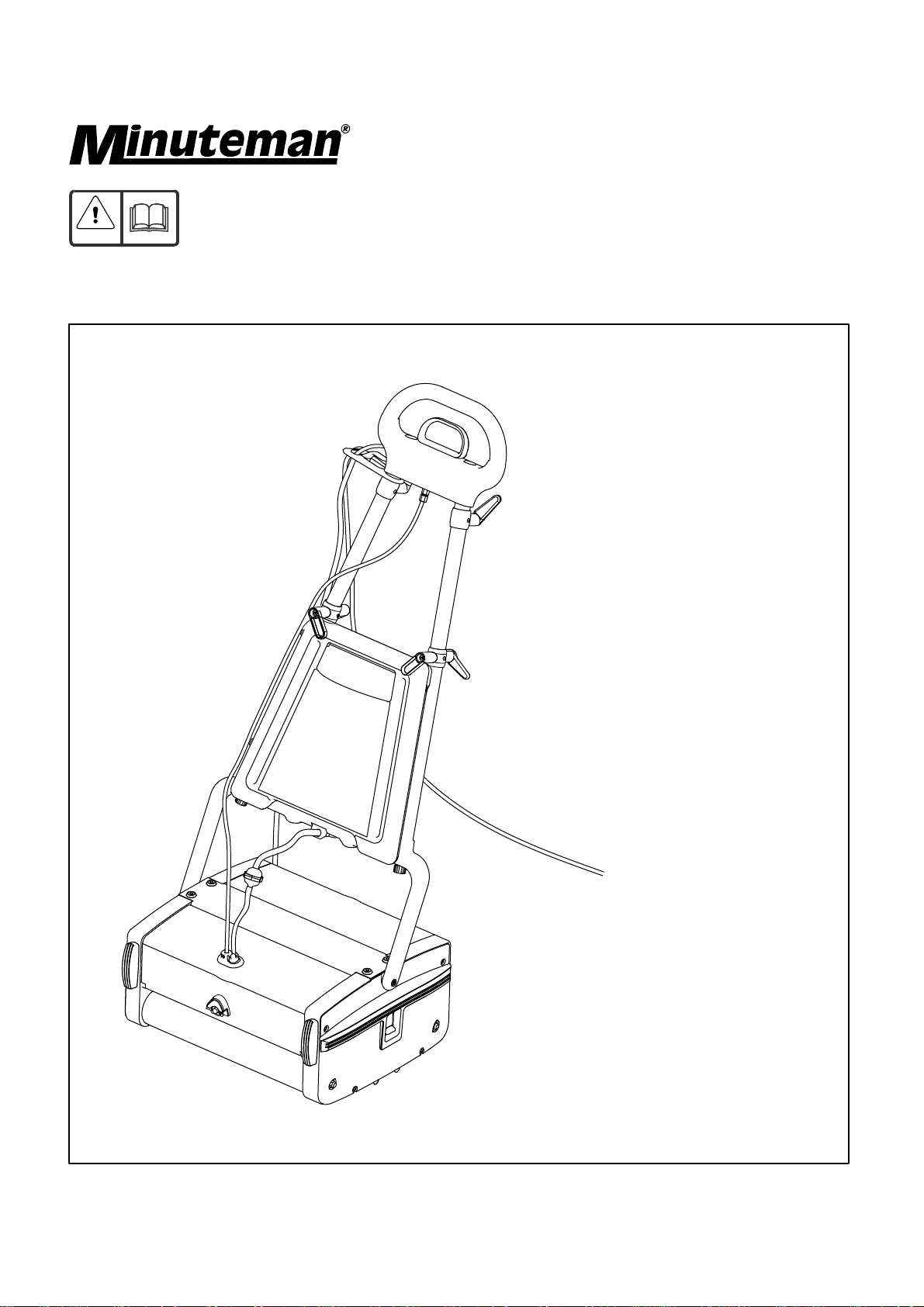
Port A Scrub
Floor Scrubbing Machine
Page 2

Contents
Instruction Manual
Product information................................................................................................
Important safety instructions...................................................................................
Technical specification............................................................................................
Know your machine................................................................................................
Working principle....................................................................................................
Preparing for use...................................................................................................
Assembly...............................................................................................................
Brush selection guide............................................................................................
Controls..................................................................................................................
Operating the machine...........................................................................................
3
3
4
5
5
5
6
6
7
7,8
Electrical diagram..................................................................................................
Accessories...........................................................................................................
Upkeep of your PORT A SCRUB...........................................................................
Spare Parts Manual
Housing - Drive Side...............................................................................................
Housing-Idle Side..................................................................................................
Pump housing........................................................................................................
Lever and guide link mechanism............................................................................
Handle group..........................................................................................................
Motor,drum and bridge assembly...........................................................................
8
9
9
11
13,15
17
19
21
23
Accessories...........................................................................................................
25
Page 3

Instruction Manual
Product Information
The Minuteman Machine is an ideal machine to clean floors in small and
medium areas like offices, hospitals, restaurants, shopping complexes and many commercial applications. It
sprays plain water / detergent solution, scrubs and picks up the dirty water - all in a single pass. The Port A
Scrub hasdifferentoptional brushes to suit a variety of applications. This machine can be used only on smooth
evenfloorslikeMosaic,alltypeofstonefloors,PVC,Short-pilecarpet,Woodand ProfiledRubber.Itshouldnot
beusedonroughunevensurfaces..
PORT A SCRUB
Important Safety Instructions
Please read the following instructions completely before operating the machine. Any violation of the
samewillnotonlyinvalidatethewarranty, butalsomay resultina safetyhazard.
Themachine must be unpacked andassembledin accordance with these instructions before connectingto
the electricalsupply.
·
This machine should always be connected to a fully grounded power supply of the right voltage and
frequency.
·
Keep the power supply cord away from moving parts. During operation, hazard may occur when running
machineoverthesupplycord.
·
The machine must be disconnected from the mains supply (by pulling the plug out) before changing the
brushes,cleaningthemachineand,formaintenance.
·
Warning! Use only the brushes/accessories strictly as per the instruction manual. Usage of any other
brushes/accessoriescancausesafetyproblems.
·
Periodicallyinspect thecordfor possibledamage.Thedamagedcord mustbereplacedwiththespecialcord
availablefromthemanufactureroranauthorizedserviceagent.
·
DO NOT leave the machine connected to the power supply when not in use; always remove the plug from
themainssocket.
·
DONOTusewhere hazardousdustis present.
·
DONOTusemachine nearflammableliquids.
·
DONOTusein anexplosiveatmosphere.
·
DONOTusein gradientsurface.
·
DONOTkeepthe machinewithhandle lowered,whenthe machineisin workingmode.
Guidelinesfor theoperator
·
Operators must be fully trained in accordance with these instructions, able to perform routine upkeep of the
machineandcorrectselectionofbrushes.
·
Operatorsshouldbe physicallycapabletomaneuvertransportandoperatethemachine.
·
DONOTrunthe machinedry,asthis coulddamagethe floorsurfaceor themachineitself.
·
Takeadequatecare toholdthe machinefirmlywhile installingand removingthebrush.
·
Neveruseexcessivefoamingorhighlycorrosivecleaningsolutions.
·
Whileoperatingonafloodedfloor,alwaysensure thatthewater leveldoesnot exceed1/4”.
·
DONOToperatethis machineonrough unevensurfacelike industrialconcretefloor.
·
Donotcleanthemachineusingwater jet.
·
Ensureallpartsarefittedproperlybeforeoperation.
3
Page 4

Technical Specification
Description
Model
Mains supply
Power
Brush Speed
Cleaning Capacity
Cleaning width
Fresh water tank capacity
Overall dimensions
Height with handle
Height without handle
Width
Units
--
-W
rpm
2
ft /hr
inch
gallon
inch
inch
inch
Specification
M12110
100-110 VAC 10% 60Hz, Single Phase
±
750+26
780
3,800
12.5
1
43.75
8.25
17.32
Length
Weight
Description
Model
Mains supply
Power
Brush Speed
Cleaning Capacity
Cleaning width
Fresh water tank capacity
Overall dimensions
inch
lbs
Units
--
-W
rpm
2
ft /hr
inch
gallon
14.88
54
Specification
M12230
230 VAC 10% 50Hz, Single Phase
±
600+26
650
3,800
12.5
1
Height with handle
Height without handle
Width
Length
Weight
4
inch
inch
inch
inch
lbs
43.75
8.25
17.32
14.88
54
Page 5
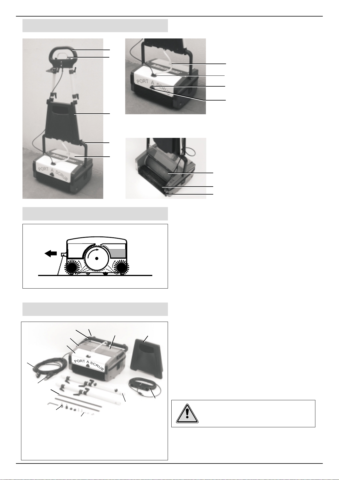
Know your machine
(1)
(2)
(3)
Top handle
(1)
Liquid discharge control
(2)
(6)
(7)
(8)
(9)
handle
(3) Tank
(4) Bottom handle
(5) Dirty water tank
(6) Filter
(7) Lid Cap
(8) Boot
Working Principle
Front
(4)
(5)
(9) Nozzle
(10) Conveyor drum
(11) Brush
(10)
(12) Pedal
(11)
(12)
1. Cleaning liquid in the fresh water tank is made to
sprayonthefloortobewashed. .
2. The counter rotating brushes scrubs the floor and
alsothrowsthe dirty water on the Conveyordrum.The
frontbrush doesmostofthe scrubbing anddrying.The
rear brush completes the scrubbing and collects the
remainingwater offthefloor.
3.Ablade fitted to the dirty water tank wipes the drum.
Preparing for use
12
2
3
10
9
7
13
1. Bottom handle
2. Machine body
3. Pump Housing
4. Auxillary Tank
5. Top handle &
pull cable
6. Handle LH & RH
7. Brush shafts (2)
8. Screws & washers
9. Cable retainer
10. Power cord
1
11
4
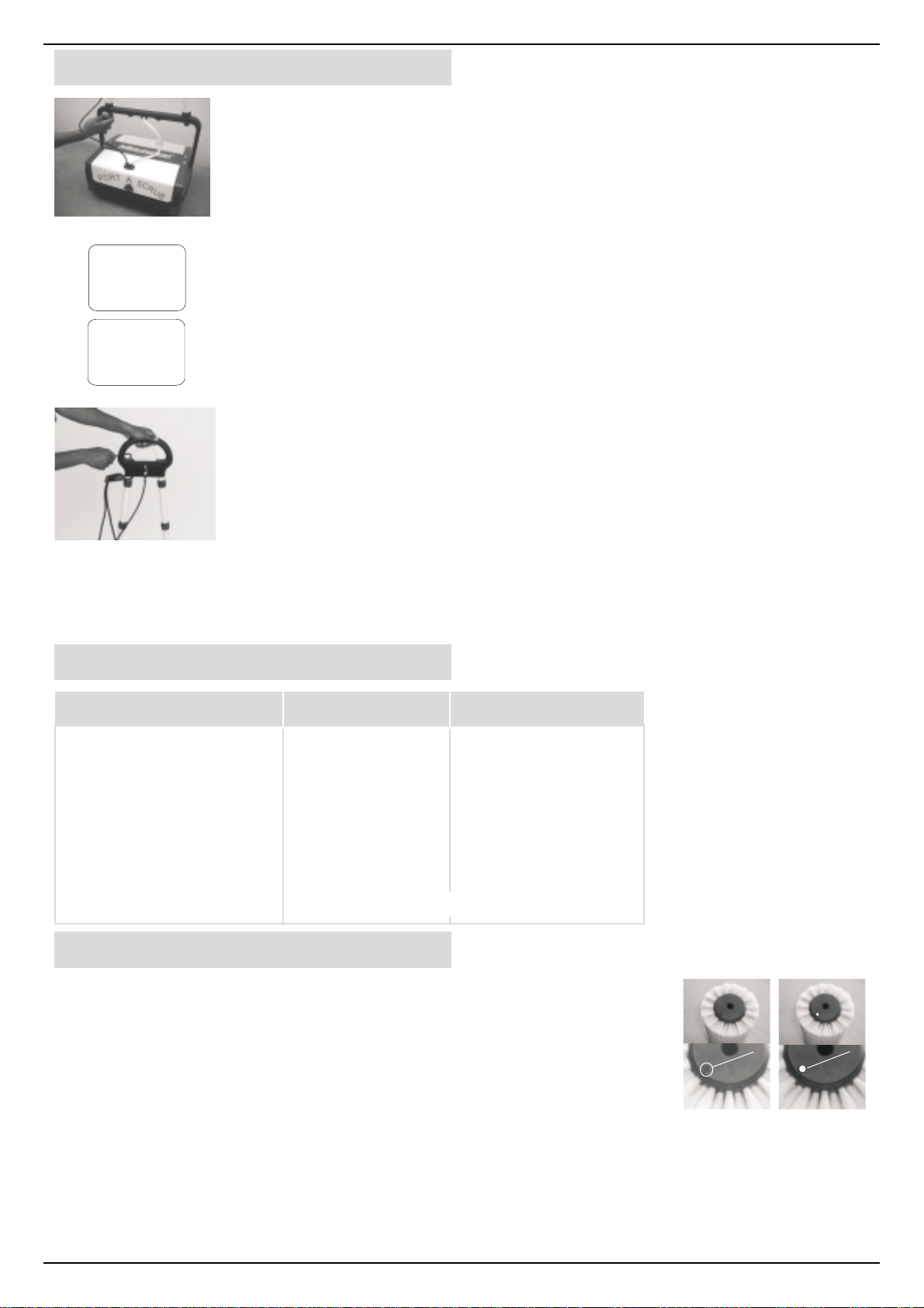
1. Tosave packing space and to ensure the safety of
themachine during transporting, the PORTASCRUB
comes to you with its handle dismantled. Ensure that
the listed parts are present as shown and identify
them in order to understand the assembly
instructions.
2. Remove the hook which holds the bottom handle
with the machine body while holding the bottom
handle.
6
8
11.Dirty water tank
12. Hook
13. Knob
5
Warning! Since the bottom handle is spring
loaded, the casual removal of the hook may
result in sudden springing back leading to
possibleinjuryto personnel.
5
Page 6
Assembly
1. Insert the two tubular handles into the bottom handle and secure them using
knob(2 Nos)bytighteninglightly.Ensurethatthehandles are assembledaccording
totheirmarkedpositionandthecableholdinghooks arepointingtowards therear.
2.Slidetheelectriccableretainerinto thetopportion ofRHhandle.
3. Fit the top handle over the tubular handles and secure them with washer and
RIGHT
BOTTOM
REAR
LEFT
screw (2 sets). Ensure that the label on the top handle is facing the front of the
machine. Now tighten firmly both the knobs and screws alternately. Insert the
dummycapsprovidedto coverthescrews (2nos)in thetophandle.
4.PassthefreeendofthepullcablethroughtheplasticguideinRHHandle.
BOTTOM
REAR
5.Fixtheauxillarytankfirmlyinto thebottomhandle byholdingthe tophandle.
6.Rotatetheknob toholdthe auxillarytank.
7. The brushes are only loosely packed in the machine for transit, therefore the
brush shafts must be fitted before operating the machine. Push the shafts through
thebrushes from the sideof the machine. Toremove brushes, push thebrush shaft
out from the side of the machine using the fingers and withdraw the shaft. Normally
standard brush type will be supplied with the machine. Brushes shall be selected
according to the type of floor surface to be cleaned, and the degree of dirt to be
removed,pleasereferBrushSelectionGuide.
8.Nowmachineisreadyforuse.
Brush Selection Guide
Type of floor First time cleaning Maintenance cleaning
All natural stone floors,
Standard Soft
Ceramic, Mosaic, Wood,
Profiled rubber, Vinyl, PVC,
Short pile carpet
Marble Granite
Smooth concrete
Escalator
Others
Soft
Soft
Hard
Escalator
Soft
Soft
Standard
Escalator
To suit individual floor conditions
Refer Page 25 for Brush Selection
Brush identification
Thisisapplicablewhenthecustomerhasmorethanonesetofbrushesofsametype.
Example:2ormoresetsof StandardBrush
CustomersmaynotinterestedtousesamebrushesinBedroom/Kitchen/germfree
area which is already been used in other areas like Corridor / Bathroom / Oil or
chemical deposited areas. It is difficult for the customers to identify the particular
brush which is used in certain area.To make this easy,Brush buttons of colors RED,
BLUE,WHITEandYELLOWarepackedwiththe machine. Customers shall plug the
(a)
(a) Hole provided for plugging button.
(b) Brush with button plugged.
(b)
buttons on the hole provided in the brush as shown. This helps the customer to
identifytheparticularbrush bykeepingthe button(color)as reference.
6
Page 7
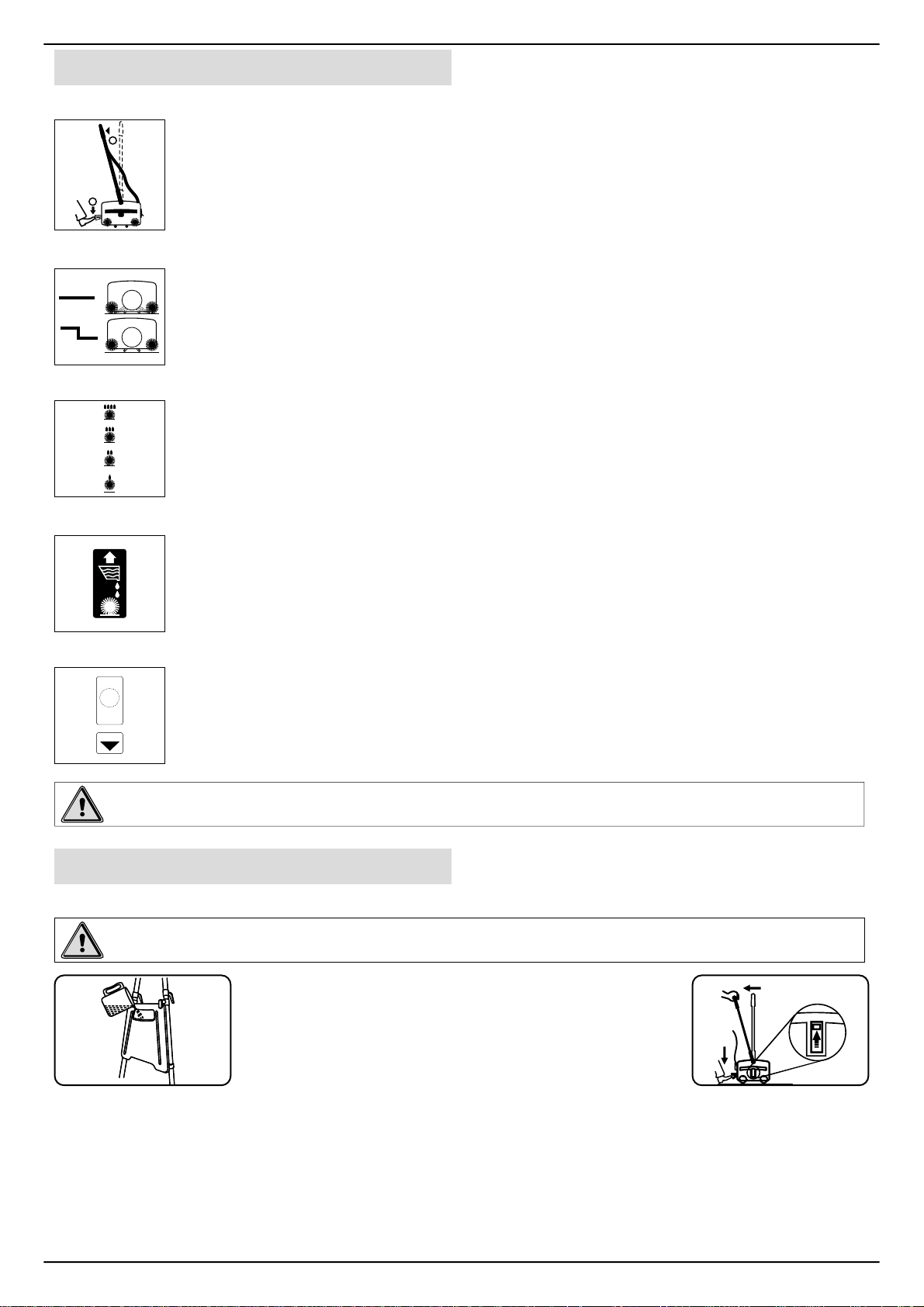
Controls
On/Off Control
OFFON
2
1
Transport/Working Model Control
Brush Contact Control
Cleaning Liquid Discharge Control
Bypressing the pedal lightly with your foot, pull back the handle a little to start the motor.The
brushes and the drum starts rotating. Pulling the handle further without pressing the pedal,
lowersthemachineandengagestherotatingbrushesontothefloor.To stop working, take the
handletotheverticalposition.
Slidethis knob toTOPposition to operatethemachine.Slidethisknob to BOTTOMpositionto
movethemachinefromone placetoother placeandto parkthe machine.Bykeeping theknob
totopposition(workingmode)andmovingthemachinewilldamagethebrushes.
Brush contact with the floor is adjustable in 4 steps, contact is MINIMUM when the knob is
fullydown and MAXIMUMwhenitis fully raised. Thishelpsyouto compensate forthewear
ofbrushes and also tocontrol the scrubbing effect.Ifthere is no machine movement, when
the handle lower down fully (working mode), change the knob position to one step up.
By pulling, the liquid discharge control handle up, the cleaning liquid is made to spray on the
floor. The spraying stops once the liquid discharge control handle is released.
Motor Overload Protector
WAIT
30
SECONDS
BEFORE
RESET
PRESS
!
In the event of motor getting overloaded due to improper power supply or unexpected
obstruction to the brush/drum rotation, the over load protector trips and protects the motor
fromdamage. If this happens,identifythecause,correct it and,resettheprotectorbutton after
minimum30secondsfromtrippingbypressing the over load protector manually and continue
working.
Warning! should the machine fail to operate, contact the supplier from whom you purchased the
machine.
Operating the machine
Before the washing operation starts
Warning!Precleaningof floorismust beforeusingthe PORTASCRUB.
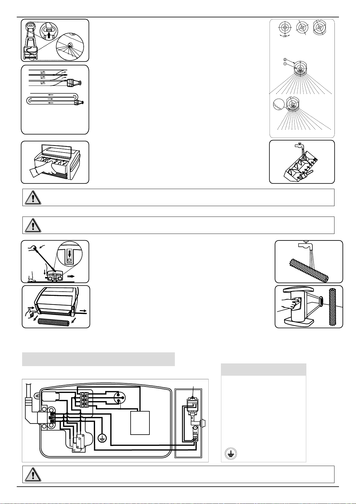
1. Fill cleaning liquid in fresh water tank (Fig-i)
2. Insert the plug into mains 3-pin socket.
3.Ensure that the brushes are fitted properly.
4.Slide the transport/working mode control knob to TOP
(i) (ii)
(working) position (Fig-ii).
3
ON
OFF
2
1
Recommended washing sequence
1. Start the machine by pressing the pedal and pulling the handle back.
2. Move forward, while sparingly pulling the liquid discharge control handle (Fig-iii). This handle should not
be kept pulled all the time. The duration and frequency of pulling and releasing has to be adjusted suitable
to match with the type of floor, extent of dirt. etc. For ceramic & granite floors, apply very little water.
7
Page 8
(a)
(b)
(a) Recommended pattern for
small rooms
(b) Recommended pattern for
large halls
Warning!Avoidtouching thesharpedge ofdirtywater tank.it maycauseinjury tohands.
3.Stoptheliquid dischargeapproximately onefoot before theend
offorwardmotion.continuetomoveforward up to the wall without
pullingthepull handle.
Sprayangle / area can be controlled by the user according to their
(iii)
requirements. It also prevents water / solutions sprayed in the
cleaned area. Spray angle of the solution is made to adjust using
the serrations provided in the nozzle and the nozzle holder.
Nozzle can be rotated about 28 degrees either clockwise or
counterclockwise@ theincrement of 4degree (Fig-iv).
4. Pull the machine backwards in the same track, but without
discharging any liquid. When you are reaching the starting point,
change the track and repeat steps 2 through 4. When you are
changing the track allow some overlap with the cleaned area. In
(v)
case of large halls take a U-turn and move forward. If quick drying
is desired, move on the same track, without discharging the liquid
(Fig-v)
5. When the dirty water tank is full, lift and pull the tank out of the
machine (Fig vi). Empty the tank and wash it in running water or
dip it in a bucket of water (Fig-vii). Clean the blades and push the
(vi)
tankintoitsplace.
(a)
(a) Nozzle at normal position
(b) Nozzle at rotated position
(c) Nozzle inserted inside the holder
at rotated position
(b) (c)
(iv)
(vii)
1. Nozzle
2. Nozzle holder
Care of the machine
Warning! Before undertaking the cleaning operations switch off the machine and unplug from the
electricalsupply.
1.Move the Transport / Working mode control knob to BOTTOM
(Transport)position(Fig-viii).
2. Disconnect the power supply by unplugging the electrical plug
andwindthe cableover cableholders inthehandle.
3.Pullout thedirty watertank andwash itcompletely.
(viii)
4.Topreventpossibleclogging offilter,draincleaning liquid
5.Removethe brushesby pushingthe brushshaftout (Fig-ix).
6. Wash the brushes either by dipping in a bucket/sink or in
1
runningwater(Fig-x).
2
7. Turn the machine sideways and wipe clean the conveyor and
machinebodywith adamp cloth(Fig-xi).
3
8. Re-install the brushes after washing. It is easier to push the
(ix)
brush shaft form the right hand side (identified by the electrical
cable).
9.Keepthe machinein thesafer place.
Electrical Diagram
Abbreviations given in the diagram as listed:
W
SC
BR/W
G/Y
BK
R
MOTOR
N
RC
BL/BK
CAPACITOR
BL/BK
BR/W
CBE
BL
BR
BR
BR
BL
BR/W
PUMP
BL/BK
928748
Abbreviation/
Symbol
CBE
BR
BL
W
BK
R
G/Y
SC
RC
N
(x)
(xi)
Description
Circuit Breaker
Brown
Blue
White
Black
Red
Green / Yellow
Starting coil
Running coil
Normal
Ground
Warning!Any service or attempt to service by persons other than authorised servicing agent is not
8
recommended.
Page 9
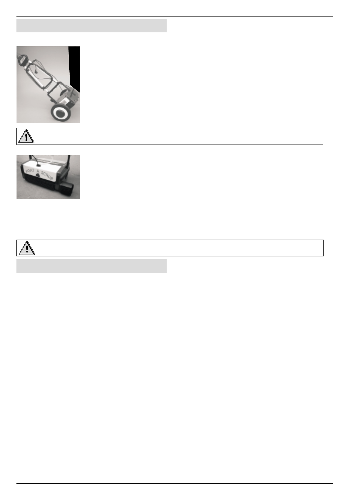
Accessories
Transporter
Warning!Emptyall liquidfromthe machinebeforeusing thetransporter.
Side Brush
Thesimplyfittedtrolleyprovidesforeaseofmovementwhentransportingthemachine.
Installing the Transporter
1.With the machine handle in the upright position place the transporter centrally
alongside the machine.
2.By holding the machine firmly, strap the velcro with the machine to fix the transporter.
3.Ensure that the velcro strap properly wrapped around the bottom handle.
4.Now the transporter is ready to use. The machine can then be maneuvered easily
whilst holding the top handle.
To wash the edges, the side brush shall be used. Switch off and unplug the machine
beforefittingthesidebrush.
Fittingthe sidebrush
1.Removethefrontbrushandbrushshaft.
2.Fixtheshieldassemblyandscrewitintothesideplateandtighten.
3.Insertthesidebrushthroughtheshieldand mainbrush.
Usingthe sidebrush
1.Tiltthe machineat an angle moveforward.This way,the dirty water thrown bythe sidebrush will be collectedby
therearbrush.
2.Usesidebrushonlyforwashingtheedges.
Warning!Donot usesidebrush inaroom withnowall skirting,otherwise,the wallwillget dirty.
Upkeep of your PORT A SCRUB
Togetthe maximumlifeof themachineensure thefollowing.
· Supplycord
Regularlyinspectsheath,plugandcordanchoragefordamageorlooseconnection.
Brushes
·
For maximum life wash the brushes regularly.Ensure machine is in Transport mode when not in use. Store
additionalbrushesin a vertical position to avoidbending of bristles. Check for permanentbendingof bristles
in a particular direction. This may occur if the machine is operated for several days without removing the
brushes, which is not recommended. If this occurs, reverse the brush so that the bent bristles are
automaticallystraightened.
WiperBlade
·
This may wear out after years of use. If this occurs the water collection performance will decrease. It should
bereplacedbyanauthorizedServiceAgent.
Solutionfeed filter
·
The filter prevents clogging of the spray nozzle and should be periodically cleaned. Use pressurized air/
waterforcleaning.
·
Nozzlemaintenance
Ifthe spray of the nozzlebecome blocked, slide thenozzle cover off and remove nozzlewash in clean water
andcleanusingapinandrefit.
9
Page 10

V7
32
105
19
115a
92
115
115b
7
11
63
19
28
88
87
116
115b
116a
19
11
20
80
25
19
49
114
83
84
10
24
53
9
7
19
1
59
43
42
73
13
V8
10
34
212
62
93
2
77
46
19
111
10
Page 11

Spare Parts Manual
Housing-Drive Side
Ref.
No
1 925032 CSK SCREW M4x10 4
2 925003 CRPH SCREW M3x6 6
7 925051 CSK SCREW M6x14 3
9 925114 ALLEN SCREW M6x10 2
10 925027 ALLEN SCREW M6x16 7
11 925031 ALLEN SCREW M6x20 2
13 925033 WASHER 4.2x12x1.6 4
19 925056 BEARING 6003 2RS 9
20 925062 BEARING 608 2Z 1
24 925001 BELT 500 5 M 1
25 925002 BELT 425 5 M 1
28 925012 WASHER 2
32 925018 BUMPER 1
34 925026 BUMPER 1
42 925047 BRUSH SLIDER 1
43 925048 SLIDER HOUSING 1
46 925054 SEAL 2
49 925064 PINION 1
53 925073 DRUM SPROCKET 1
59 925092 PIN 1
62 925099 O' RING 2
63 925102 SHIELD 1
73 925186 SELF TAPPING SCREW 4
77 925130 CAP 2
80 925227 GEAR HOUSING 1
83 925181 HOUSING SPROCKET 1
84 925182 SEAL 1
87 925193 GEAR – LH 1
88 925194 GEAR - RH 1
92 925219 SHIELD 2
93 925220 ROLLER 2
105 925249 BUMPER SLEEVE 3
111 925804 BRUSH SPROCKET 2
114 925813 GEAR SPROCKET 2
115 925815 IDLER ASSY 1
115a 925075 SPROCKET 1
115b 925046 HUB 2
116 925816 IDLER ASSY 1
116a 925061 SLEEVE 1
212 925221 STUB AXLE 1
V7 925150 DRIVE HOUSING 1
V8 925319 COVER 1
Part
No
Description
Size
Qty
11
Page 12

68
188
212
62
32
105
V5
93
100
58
73
13
V8
10
79
9
59
43
1
2
46
18
9
242
77
19
33
15
17
106
63
92
34
81
6
132
21
131
73
39
75
133
89
V3
90
16
12
10
94b
V2
94
94a
129
95
96
98
99
72
86
Page 13

Housing-Idle Side
Ref.
No
1 925032 CSK SCREW M4x10 4
2 925003 CRPH SCREW M3x6 6
6 925039 CSK SCREW M5x25 2
9 925114 ALLEN SCREW M6x10 2
10 925027 ALLEN SCREW M6x16 5
13 925033 WASHER 4.2x12x1.6 4
15 925100 WASHER 6.4x12x1.6 1
16 925151 WASHER 9x17x1.6 1
17 925110 SPRING WASHER M6 1
18 925059 TOOTHED WASHER M6 1
19 925056 BEARING 6003 2RS 2
21 925063 WIRE TIE 3
32 925018 BUMPER 1
33 925019 BUSH 2
34 925026 BUMPER 1
39 925040 STUB AXLE 1
43 925048 SLIDER HOUSING 1
46 925054 SEAL 2
58 925083 TRANSPORT SLIDER 1
59 925092 PIN 1
62 925099 O' RING 2
63 925102 SHIELD 1
68 925109 FAN COVER 1
72 925116 GROMMET 2
73 925186 SELF TAPPING SCREW 6
75 925124 CAP 1
77 925130 CAP 2
79 925147 STOPPER 1
81 925500 PEDAL 1
86 925192 NUT 2
89 925199 CONNECTOR 1
90 925200 SWITCH 2
92 925219 SHIELD 2
93 925220 ROLLER 2
94 925529 SOCKET ASSY 1
94a 925074 SOCKET 1
94b 925076 TERMINAL 3
95 925501 CABLE 1
96 925502 CABLE 1
98 925504 CABLE 1
99 925505 CABLE 1
Part
No
Description
Size
Qty
13
Page 14

68
188
212
62
32
105
V5
93
100
58
73
13
V8
10
79
9
59
43
1
2
46
18
9
242
77
19
33
15
17
106
63
92
34
81
6
132
21
131
73
75
133
89
V3
90
39
16
14
10
94b
V2
94
94a
129
95
96
98
99
72
86
Page 15

Housing-Idle Side
Ref.
No
100 925152 SPRING-PEDAL
105 925249 BUMPER SLEEVE
106 925161 CSK SCREW M4x8
129 925015 LEVER SWITCH ACT
131 925041 INSULATION TOP
132 925044 INSULATION BOTTOM
133 925101 NUT
188 925207 SLEEVE TIE ROD
212 925221 STUB AXLE
242 925347 CLAMP WIRE
V2 925534 CAPACITOR (M12230) 1
V3 925173 CIRCUIT BREAKER (M12110) 1
V5 925153 IDLE HOUSING (M12110) 1
V8 925319 COVER 1
Part
No
925166 CIRCUIT BREAKER (M12230) 1
925154 IDLE HOUSING (M12230) 1
Description
Size
Qty
1
3
1
1
1
1
1
3
1
1
15
Page 16

173
123
122b
123a
121
1
165
181
164
162
163
167
155
186
72
180
159
169
182
187
176
184
1
101
185
V9
183
168
106
174
158
106
154
M12110
165
244
72
246
177
170
175
V2
102
245
248
16
245
247
Page 17

Pump Housing
Ref.
No
1 925032 CSK SCREW M4x10 5
72 925116 GROMMET 2
101 925160 O-RING-PUMP 1
102 925077 FILTER 1
106 925161 CSK SCREW M4x8 8
121 925832 DIRTY WATER TANK 1
122b 925162 LID PAD 2
123 925836 LID-DIRTY WATER 1
123a 925132 LID-DIRTY WATER 1
154 925128 HOSE-275(10.8) 1
155 925163 INSULATION 1
158 925164 HOSE CLIP 1
159 925165 NOZZLE 1
162 925167 BOOT 1
163 925168 SCREW M3X30 2
164 925169 HEX NUT M3 2
165 925170 HEX NUT M4 3
167 925187 SWITCH 2
168 925204 STRIP LID 2
169 925224 EXTENSION BUSH 1
170 925233 HOSE-165(6.5) 2
173 925261 HOSE CONNECTOR 1
174 925262 BOOT-LID 1
175 925506 CABLE 1
176 925511 ADAPTOR NOZZLE 1
177 925573 CABLE 1
180 925171 SEAL NOZZLE 1
181 925173 BASE SWITCH 1
182 925174 LEVER 1
183 925175 CLAMP 1
184 925176 SUPPORT RING 2
185 925177 PUMP HOUSING 1
186 925178 LID 1
187 925179 SPACER 1
V9 925210 PUMP (M12230) 1
165 925170 HEX NUT M4 2
244 925011 CLAMP CAPACITOR (M12110)
245 925013 CSK SCREW M4x12 8
246 925016 GROMMET (M12110)
247 925020 PUMP HOUSING (M12110)
248 925021 CABLE (M12110)
V2 925536 CAPACITOR (M12110) 1
V9 925203 PUMP (M12110) 1
Part
No
Description
Size
for M12110
Qty
1
2
1
1
17
Page 18

4
26
29
128
119a
47
91
76
78
41
76
120a
120
82
119
45
26
119a
118a
119
64
118
76
113
18
Page 19

Lever and Guide Link Mechanism
Ref.
No
4 925104 CRPH SCREW M4x12 2
26 925008 CLEVIS PIN 5
29 925014 CLEVIS PIN 1
41 925043 LINK 1
45 925053 SHIELD 8
47 925055 LEVER 2
64 925105 LEVER BUTTON 4
76 925129 CIRCLIP 6
78 925139 LINK GUIDE 1
82 925180 SPRING 1
91 925212 BUSH 1
113 925810 W HEEL 4
118 925822 LEVER ASSY 1
118a 925085 LEVER 1
119 925823 LEVER ASSY 2
119a 925086 LEVER 2
120 925824 LEVER ASSY 1
120a 925087 LEVER 1
128 925050 LEVER SWITCH 1
Part
No
Description
Size
Qty
19
Page 20

189
57
35
227
104
60
225
3
224
231
11
48
4
12
117
153
44
71
52
225
73
65
226
4
66
224
228
23
73
V4
229
161d
161c
161b
161a
152
179
12
126
160
4
230
161
135
160c
160b
160a
172
20
Page 21

Handle Group
Ref.
No
3 925058 CRPH SCREW M4x8 1
4 925104 CRPH SCREW M4x12 10
11 925031 ALLEN SCREW M6x20 2
12 925088 WASHER 6.4x18x2 4
23 925098 CABLE RETAINER 1
35 925028 CLAMP 1
44 925049 PULL HANDLE 1
48 925057 CAP 1
52 925069 BASE-CABLE HOLDER 2
57 925082 CLAMP 1
60 925096 NUT 1
65 925106 SPRING 6
66 925107 WASHER 6
71 925115 PLUG 2
73 925186 SELF TAPPING SCREW 10
104 925184 PULL CABLE-P 1
117 925818 TOP HANDLE 1
126 925103 KNOB 2
135 925089 BOTTOM HANDLE 1
152 925127 GASKET 1
153 925111 TANK-4l 1
160 925117 BASE VALVE 1
160a 925118 BASE 1
160b 925119 SEAL 1
160c 925120 CAP-VALVE 1
161 925135 VALVE 1
161a 925122 BODY-VALVE 1
161b 925540 SEAL 1
161c 925123 SPRING 1
161d 925125 CAP-SPRING 1
172 925260 PLATE 1
179 925126 NUT 1
189 925274 SLEEVE 1
224 925305 KNOB-CABLE HOLDER-II 2
225 925306 KNOB-CABLE HOLDER-I 2
226 925307 KNOB-TANK HOLDER-LH 1
227 925308 KNOB-TANK HOLDER-RH 1
228 925339 BASE-CABLE AND TANK HOLDER 2
229 925340 GUIDE 1
230 928633 PIPE-LH 1
231 928634 PIPE-RH 1
V4 925922 POWER CORD 1
Part
No
Description
Size
Qty
21
Page 22

134a
134
134b
8
5
15
51
70
67
38
54
55
31
56
62
14
22
37
69
28
7
V6
V1
50
27
22
112
Page 23

Motor, Drum and Bridge Assembly
Ref.
No
5 925136 HEX NUT M6 3
7 925051 CSK SCREW M6x14 4
8 925090 ALLEN SCREW M4x10 2
14 925080 WASHER 5.2x10x1.6 2
15 925100 WASHER 6.4x12x1.6 3
22 925084 GRUB SCREW M5x12 2
27 925009 BUSH 4
28 925012 WASHER 4
31 925017 WASHER 6
37 925037 SPRING 1
38 925038 SPRING 1
50 925065 HEX SHAFT 2
51 925068 WASHER 2
54 925078 TIE ROD 3
55 925079 SHAFT 1
56 925081 ROLLER 6
62 925099 O' RING 12
67 925108 BUSH 2
69 925112 BUSH 1
70 925113 BUSH 1
112 925808 BRUSH SHAFT 2
134 925067 DRUM ASSY 1
134a 925070 DRUM 1
134b 925071 DRUM SLEEVE 1
V1 925762 MOTOR (M12110) 1
V6 928548 BRIDGE 1
Part
No
925761 MOTOR (M12230) 1
Description
Size
Qty
23
Page 24

Accessories
Transporter
7
6a
Side Brush Assy
6c
6
6a
6b
1
2
12
2
3
10
10
11
1
3
10
5
4
8
4
9
8
5
6
24
Page 25

Accessories
925904-TRANSPORTER
SL
NO
1
2
3
4
5
6
6a
6b
6c
7
8
9
10
11
12
PART NO DESCRIPTION QTY
925881
925155
925156
925157
925158
925137
925138
925140
925141
925159
925142
925143
925144
925878
925879
FRAME
CLAMP
FIXED STRIP (VELCRO)
FLEXIBLE STRIP(VELCRO)
PLATE
TYRE
BUSH-WHEEL RIM
WHEEL RIM
TYRE-MAIN WHEEL
CAP WHEEL
WASHER
CIRCLIPA17x1
CRPH SCREW M4x25
STOPPER TOP
STOPPER BOTTOM
1
1
1
1
1
2
4
2
2
2
4
2
6
1
2
SIDE BRUSH ASSY
DESCRIPTIONSL.
NO
1
SHIELD
2
BUSH
3
SHAFT
4
SIDE BRUSH
5
WASHER
6
ALLEN SCREW M5x20
BRUSH
SL
NO
1
2
3
4
PART NO DESCRIPTION
925901
925902
925903
925908
925907
STANDARD
925766
925172
925764
925855
925145
925146
BRUSH-STD
BRUSH-POLISHING
BRUSH-SCRUBBING
BRUSH-ESCALATOR
925927
ESCALATOR
925766
925172
925764
925595
925145
925146
QTY
1
1
1
1
1
1
Note: Since the companies policy is to continuously improve the product, these could be changed without prior notice.
25
Page 26

26
Page 27

27
Page 28

LIMITED WARRANTY
Minuteman International, Inc. warrants to the original purchaser/user that this product is free from defects in
workmanship and materials under normal use and service for a period of one year from date ofpurchase. In addition,
Minuteman International, Inc will, at its option, honor labor warranty claims for the first 6 months from date of sale,
provided such claims are submitted through and approved by factory authorized repair stations. Minuteman
International,Inc will,at itsoption,repairorreplace withoutcharge, exceptfor transportationcosts, partsthatfail under
normal use and service when operated and maintained in accordance with the applicable operation and instruction
manuals.
This warranty does not apply to normal wear,or to items whose life isdependent on their use and care, such as belts,
cords, switches, hoses, rubber parts, electrical motor components or adjustments. Parts not manufactured by
MinutemanInternational, Inc suchas engines, batteries, batterychargers,hydraulic pumps, andtiresare covered by
and subject to the warranties and/or guarantees of their manufacturers. Please contact Minuteman International, Inc
forproceduresin warrantyclaims againstthese manufacturers.
Special warning to purchaser - Use of replacement filters and / or pre-filters not manufactured by Minuteman
International,Inc.or itsdesignatedlicenseeswillvoid allwarranties expressedor implied.
Apotentialhealthhazardexistswithoutexact originalequipmentreplacement.
Allwarranted items become the sole property of Minuteman International, Inc. or its original manufacturer,whichever
thecasemay be.
Minuteman International, Inc. disclaims any implied warranty, including the warranty of merchantability and the
warranty of fitness for a particular purpose. Minuteman International Inc. assumes no responsibility for any special,
incidentalorconsequential damages.
Thislimited warrantyis applicableonly onthe U.S.A.and Canada,and isextendedonlytothe originaluser /purchaser
of this product. Customers outside the U. S. A and Canada should contact their local distributor for export warranty
policies. Minuteman International Inc. is not responsible for costs or repairs performed by persons other than those
specifically authorized by Minuteman International, Inc. This warranty does not apply to damage from transportation,
alterations by unauthorized person, misuse or abuse of the equipment, use ofnon-compatiblechemicals,or damage
toproperty,orlossof incomedue tomalfunctionsoftheproduct.
Ifadifficulty developswiththis machine,you shouldcontactthe dealerfrom whomitwaspurchased.
This warranty gives you specific legal rights, and you may have other rights, which vary from state to state. Some
states do not allow the exclusion of limitation of special, incidental or consequential damages, or limitations on how
longanimplied warrantylasts,sotheabove exclusionsand limitationsmaynot applyto you.
World Headquarters
Minuteman International, Inc.
111 South Rohlwing Road
Addison, Illinois 60101
(630) 627-6900
FAX (630) 627-1130
Minuteman Canada, Inc.
2210 Drew Road,
Mississauga, Ontario
L5S 1B1
(905) 673-3222
FAX (905) 673-5161
928747
Printed in U.S.A
 Loading...