

Page 1
M12110
M12230
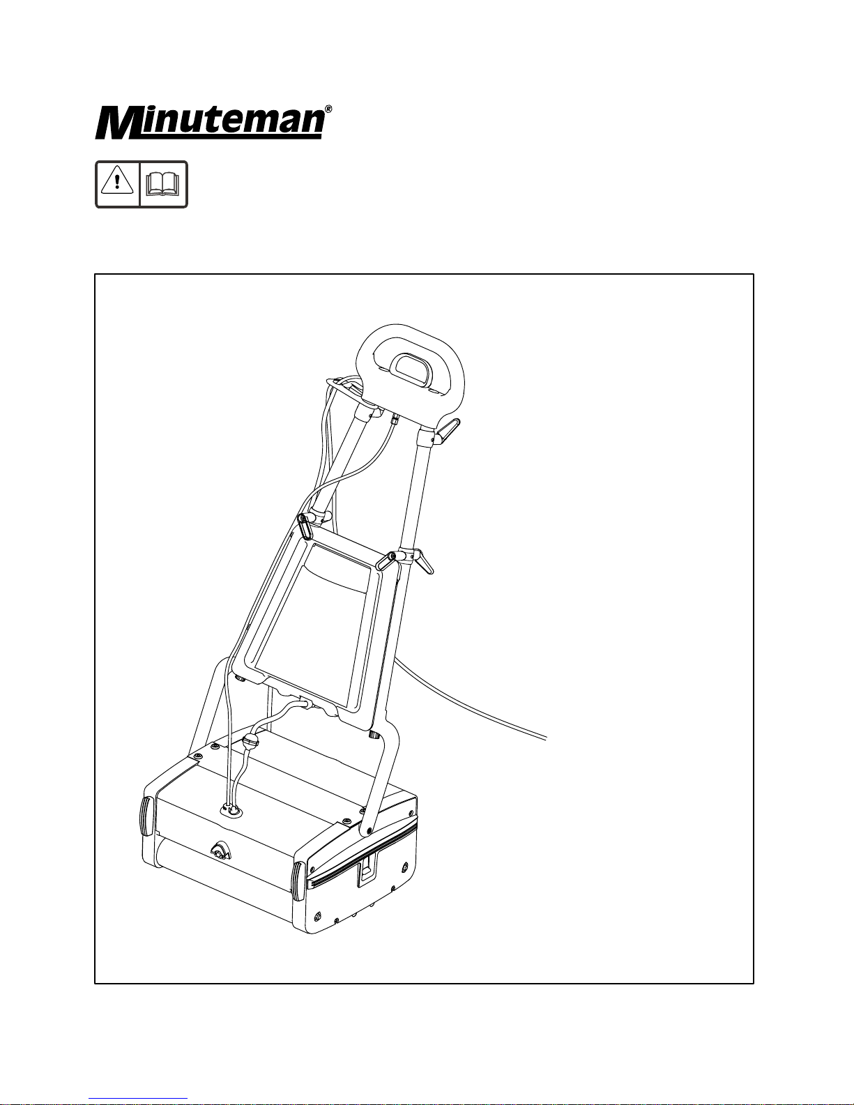
Port A Scrub
Floor Scrubbing Machine
Rev-D
Page 2

Contents
Instruction Manual
Spare Parts Manual
Product information................................................................................................
Important safety instructions...................................................................................
Technical specification............................................................................................
Know your machine................................................................................................
Working principle....................................................................................................
Preparing for use...................................................................................................
Assembly...............................................................................................................
Brush selection guide............................................................................................
Controls..................................................................................................................
Operating the machine...........................................................................................
Electrical diagram..................................................................................................
Accessories...........................................................................................................
Upkeep of your PORT A SCRUB...........................................................................
Housing - Drive Side...............................................................................................
Housing-Idle Side..................................................................................................
Pump housing........................................................................................................
Lever and guide link mechanism............................................................................
Handle group..........................................................................................................
Motor,drum and bridge assembly...........................................................................
Accessories...........................................................................................................
3
3
4
5
5
5
6
6
7
7,8
8
9
9
11
13,15
17
19
21
23
25
Page 3

The Minuteman Machine is an ideal machine to clean floors in small and
medium areas like offices, hospitals, restaurants, shopping complexes and many commercial applications. It
sprays plain water / detergent solution, scrubs and picks up the dirty water - all in a single pass. The Port A
Scrub hasdifferent optional brushestosuit a variety of applications. This machine can be used only on smooth
evenfloorslike Mosaic, all type ofstonefloors, PVC, Short-pile carpet, Woodand ProfiledRubber.Itshouldnot
beusedonroughunevensurfaces..
PORT A SCRUB
Product Information
Important Safety Instructions
Instruction Manual
Please read the following instructions completely before operating the machine. Any violation of the
samewill not onlyinvalidatethewarranty, but alsomayresultina safety hazard.
Themachinemustbeunpacked andassembledinaccordancewiththeseinstructionsbeforeconnectingto
the electricalsupply.
This machine should always be connected to a fully grounded power supply of the right voltage and
frequency.
Keep the power supply cord away from moving parts. During operation, hazard may occur when running
machineover the supplycord.
The machine must be disconnected from the mains supply (by pulling the plug out) before changing the
brushes,cleaning the machineand,formaintenance.
Warning! Use only the brushes/accessories strictly as per the instruction manual. Usage of any other
brushes/accessoriescan cause safetyproblems.
Periodicallyinspect the cordforpossibledamage.The damagedcordmustbereplacedwith the specialcord
availablefrom the manufactureroranauthorizedservice agent.
DO NOT leave the machine connected to the power supply when not in use; always remove the plug from
themains socket.
DONOTusewherehazardousdustis present.
DONOTusemachinenearflammableliquids.
DONOTuseinanexplosiveatmosphere.
DONOTuseingradientsurface.
DONOTkeepthemachinewithhandle lowered,whenthemachineisin workingmode.
Operators must befully trained in accordance with these instructions, able toperform routine upkeep of the
machineand correct selectionofbrushes.
Operatorsshould be physicallycapabletomaneuvertransportandoperatethe machine.
DONOTrunthemachinedry, asthis coulddamage thefloorsurfaceorthe machine itself.
Takeadequatecareto hold themachinefirmlywhileinstalling andremovingthebrush.
Neveruse excessive foamingorhighlycorrosivecleaning solutions.
Whileoperating on afloodedfloor,alwaysensurethat the waterleveldoesnotexceed 1/4”.
DONOToperatethismachineonrough unevensurfacelikeindustrialconcretefloor.
Donot clean themachineusingwater jet.
Ensureall partsarefittedproperly beforeoperation.
·
·
·
·
·
·
·
·
·
·
·
Guidelinesfor the operator
·
·
·
·
·
·
·
·
·
3
Page 4

Technical Specification
Model
Mains supply
Power
Brush Speed
Cleaning Capacity
Cleaning width
Fresh water tank capacity
Height with handle
Height without handle
Width
Length
Weight
Overall dimensions
Description
--
-W
rpm
ft /hr
inch
gallon
2
inch
inch
inch
inch
lbs
Units
M12110
100-110 VAC 10% 60Hz, Single Phase
750+26
780
3,800
12.5
1
±
43.75
8.25
17.32
14.88
54
Specification
Model
Mains supply
Power
Brush Speed
Cleaning Capacity
Cleaning width
Fresh water tank capacity
Height with handle
Height without handle
Width
Length
Weight
Overall dimensions
Description
--
-W
rpm
ft /hr
inch
gallon
2
inch
inch
inch
inch
lbs
Units
M12230
230 VAC 10% 50Hz, Single Phase
600+26
650
3,800
12.5
1
±
43.75
8.25
17.32
14.88
54
Specification
4
Page 5
10
9
8
6
7
13
5
11
4
1
2
3
12
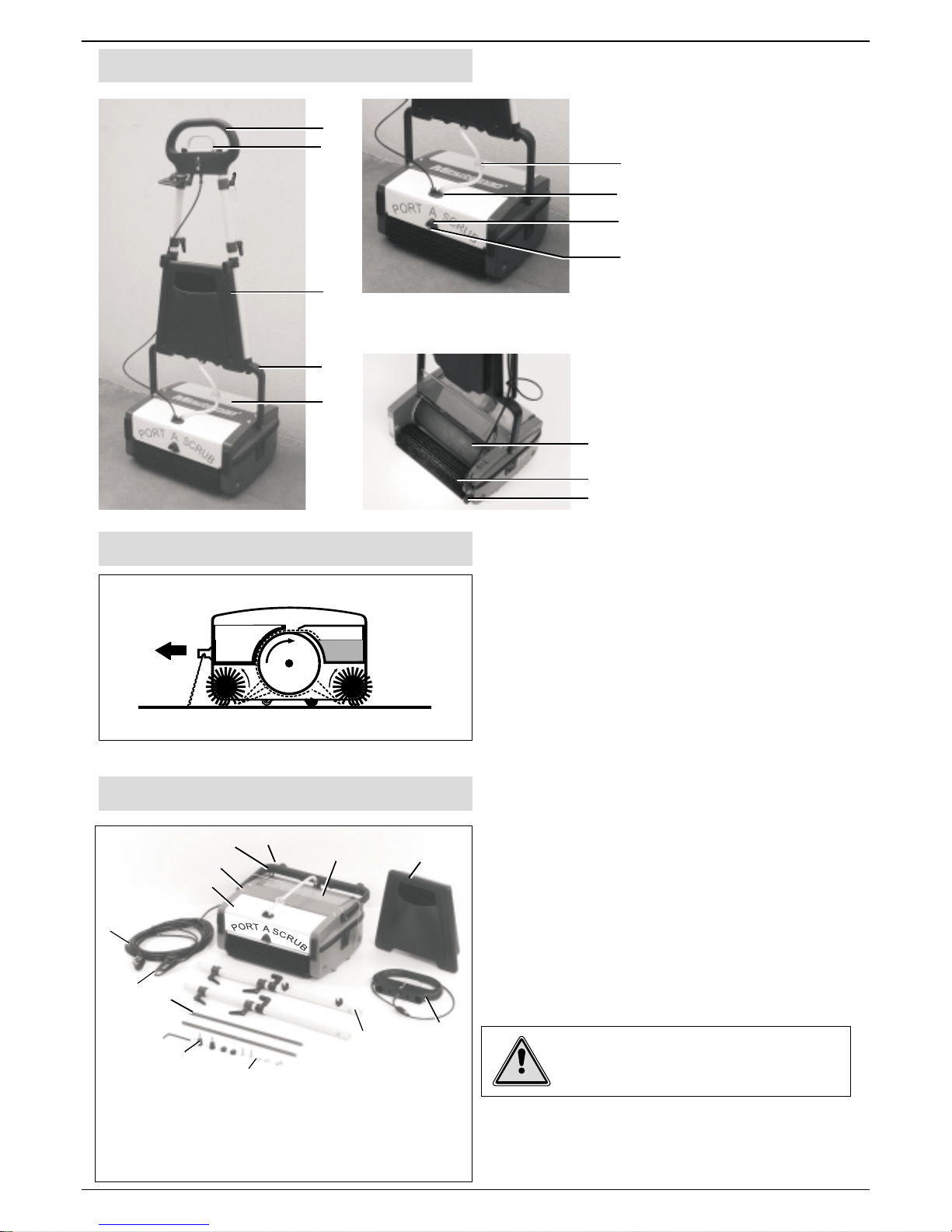
Know your machine
Working Principle
Preparing for use
(1)
(2)
(3) Tank
(4) Bottom handle
(5) Dirty water tank
(6) Filter
(7) Lid Cap
(8) Boot
(9) Nozzle
(10) Conveyor drum
(11) Brush
(12) Pedal
Top handle
Liquid discharge control
handle
1. Cleaning liquid in the fresh water tank is made to
sprayon the floortobewashed. .
2. The counter rotating brushes scrubs the floor and
alsothrows the dirty wateron the Conveyordrum.The
frontbrushdoes most of the scrubbing anddrying.The
rear brush completes the scrubbing and collects the
remainingwater offthe floor.
3.A blade fitted to the dirty water tank wipes the drum.
1. To save packing space and to ensure the safety of
themachine during transporting, the PORTASCRUB
comes to youwith itshandle dismantled. Ensurethat
the listed parts are present as shown and identify
them in order to understand the assembly
instructions.
2. Remove the hook which holds the bottom handle
with the machine body while holding the bottom
handle.
5
Front
1. Bottom handle
2. Machine body
3. Pump Housing
4. Auxillary Tank
5. Top handle &
pull cable
7. Brush shafts (2)
8. Screws & washers
9. Cable retainer
10. Power cord
6. Handle LH & RH
11.Dirty water tank
12. Hook
13. Knob
Warning! Since the bottom handle is spring
loaded, the casual removal of the hook may
result in sudden springing back leading to
possibleinjury topersonnel.
(10)
(11)
(12)
(7)
(8)
(9)
(6)
(2)
(3)
(4)
(5)
(1)
Page 6
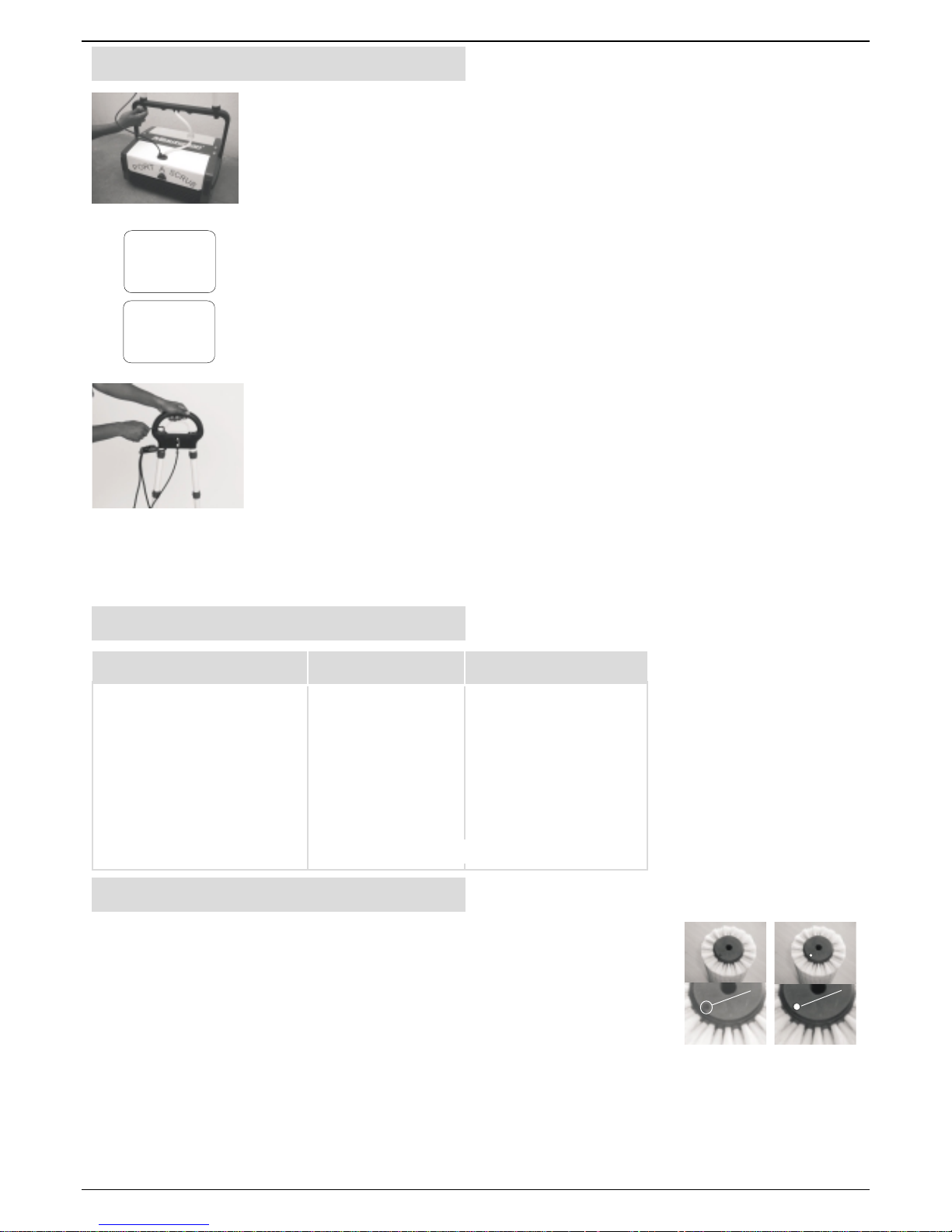
Assembly
Brush Selection Guide
LEFT
BOTTOM
REAR
RIGHT
BOTTOM
REAR
1. Insert the two tubular handles into the bottom handle and secure them using
knob(2Nos) by tightening lightly.Ensure thatthehandlesareassembledaccording
totheir marked positionandthecableholding hooks arepointingtowards therear.
2.Slide the electriccableretainerinto the topportionofRHhandle.
3. Fit the top handle over the tubular handles and secure them with washer and
screw (2 sets). Ensure that the label on the top handle is facing the front of the
machine. Now tighten firmly both the knobs and screws alternately. Insert the
dummycaps providedtocoverthescrews (2 nos)inthetophandle.
4.Pass the freeendofthepull cable throughtheplasticguidein RH Handle.
5.Fix the auxillarytankfirmlyinto the bottomhandlebyholdingthe top handle.
6.Rotate theknobtoholdthe auxillary tank.
7. The brushes are only loosely packed in the machine for transit, therefore the
brush shafts must be fitted before operating the machine. Push the shafts through
thebrushes from theside of the machine. Toremove brushes, pushthe brush shaft
out from theside of the machine using the fingers and withdrawthe shaft. Normally
standard brush type will be supplied with the machine. Brushes shall be selected
according to the type of floor surface to be cleaned, and the degree of dirt to be
removed,please refer BrushSelectionGuide.
8.Nowmachine is readyforuse.
6
All natural stone floors,
Ceramic, Mosaic, Wood,
Profiled rubber, Vinyl, PVC,
Standard Soft
Short pile carpet
Marble Granite
Smooth concrete
Escalator
Others
Soft
Soft
Hard
Escalator
To suit individual floor conditions
Soft
Soft
Standard
Escalator
Type of floor First time cleaning Maintenance cleaning
Refer Page 25 for Brush Selection
Brush identification
Thisis applicable whenthecustomerhasmore than onesetofbrushesof same type.
Example: 2 ormoresetsof StandardBrush
Customersmaynot interested to use samebrushesinBedroom / Kitchen / germfree
area which is already been used in other areas like Corridor / Bathroom / Oil or
chemical deposited areas. It is difficult for the customers to identify the particular
brush which isused incertain area. To make this easy,Brush buttons of colors RED,
BLUE,WHITE and YELLOW are packedwiththe machine. Customers shallplug the
buttons on the hole provided in the brush as shown. This helps the customer to
identifythe particularbrushbykeepingthe button (color)asreference.
(a)
(b)
(a) Hole provided for plugging button.
(b) Brush with button plugged.
Page 7
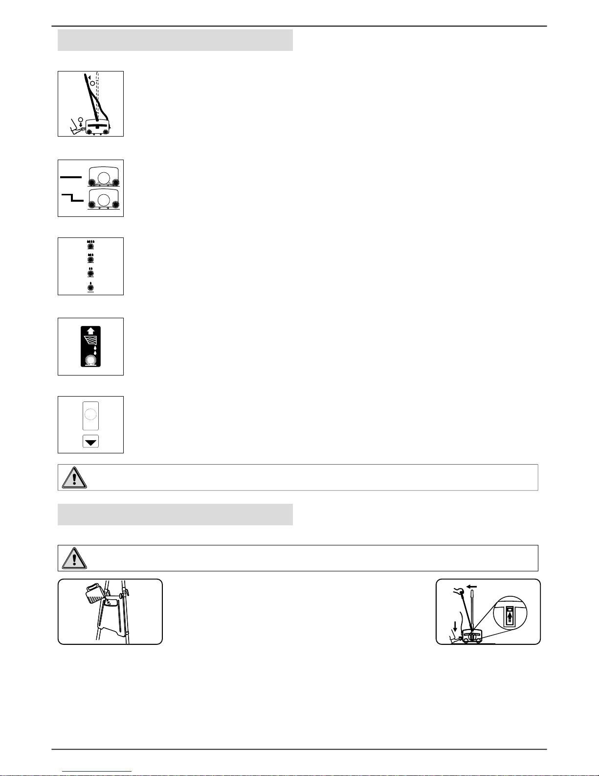
Bypressing the pedal lightly withyour foot, pull back the handle a little tostart the motor.The
brushes and the drum starts rotating. Pulling the handle further without pressing the pedal,
lowersthemachine and engages therotatingbrushesontothe floor.Tostop working, take the
handleto the verticalposition.
By pulling, the liquid discharge control handle up, the cleaning liquid is made to spray on the
floor. The spraying stops once the liquid discharge control handle is released.
Brush contact with the floor is adjustable in 4 steps, contact is MINIMUM when the knob is
fullydownandMAXIMUM when it is fully raised. Thishelpsyou to compensate for the wear
ofbrushes and also to control the scrubbing effect.Ifthere is no machine movement,when
the handle lower down fully (working mode), change the knob position to one step up.
In the event of motor getting overloaded due to improper power supply or unexpected
obstruction to the brush/drum rotation, the over load protector trips and protects the motor
fromdamage.Ifthishappens,identifythecause,correctitand,resettheprotectorbuttonafter
minimum30seconds from tripping bypressingthe over load protector manuallyandcontinue
working.
SlidethisknobtoTOPposition to operate the machine. Slide this knob to BOTTOM position to
movethe machine fromoneplacetoother place andtoparkthe machine. Bykeepingtheknob
totop position (workingmode)andmovingthe machine willdamagethebrushes.
Controls
Operating the machine
Before the washing operation starts
Recommended washing sequence
On/Off Control
Transport/Working Model Control
Brush Contact Control
Cleaning Liquid Discharge Control
Motor Overload Protector
1
2
OFFON
BEFORE
RESET
WAIT
SECONDS
30
!
PRESS
Warning! should the machine fail to operate, contact the supplier from whom you purchased the
machine.
Warning!Precleaningofflooris must beforeusingthePORTASCRUB.
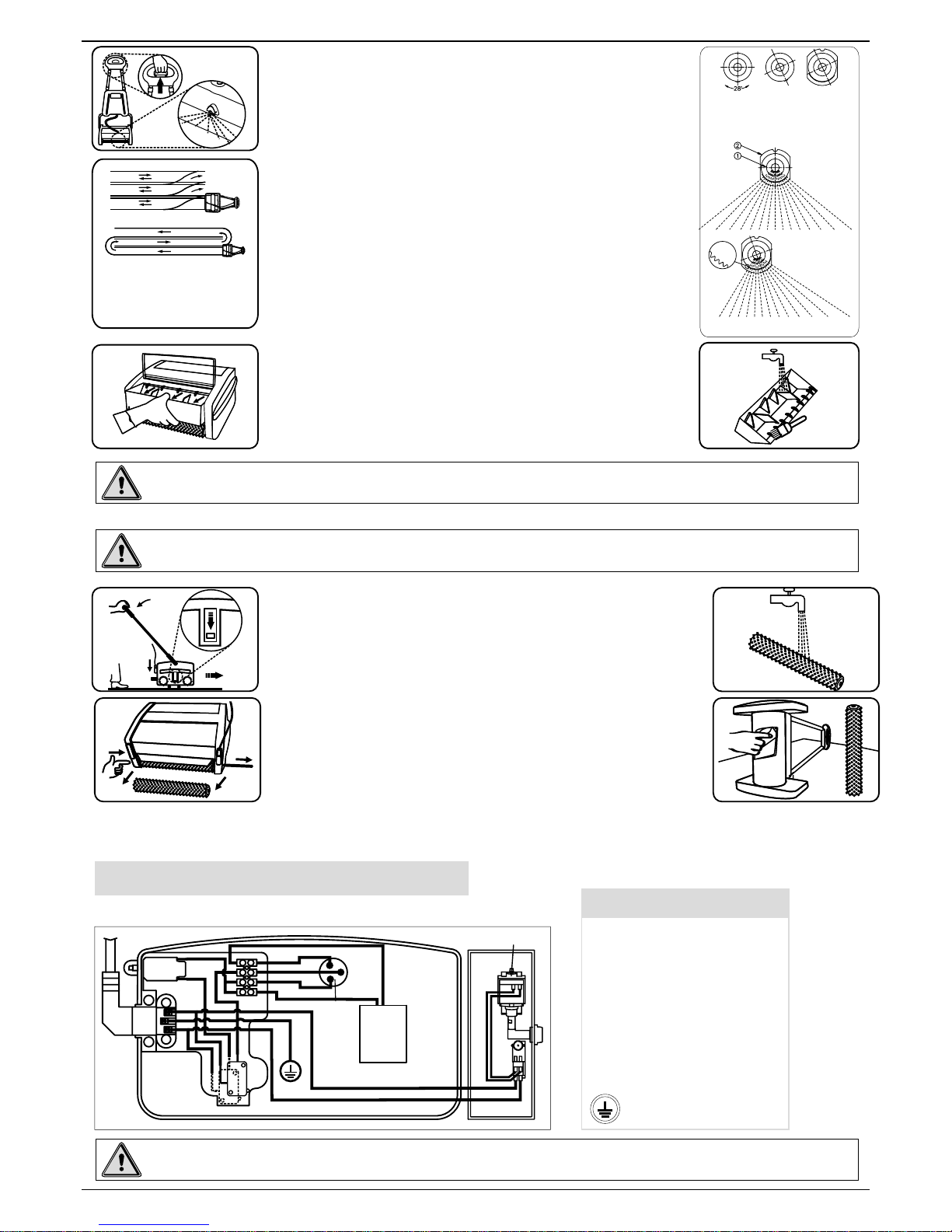
1. Fill cleaning liquid in fresh water tank (Fig-i)
2. Insert the plug into mains 3-pin socket.
3.Ensure that the brushes are fitted properly.
4.Slide the transport/working mode control knob to TOP
(working) position (Fig-ii).
1. Start the machine by pressing the pedal and pulling the handle back.
2. Move forward, while sparingly pulling the liquid discharge control handle (Fig-iii). This handle should not
be kept pulled all the time. The duration and frequency of pulling and releasing has to be adjusted suitable
to match with the type of floor, extent of dirt. etc. For ceramic & granite floors, apply very little water.
ON
3
2
1
OFF
(i) (ii)
7
Page 8
Care of the machine
3.Stopthe liquiddischargeapproximately onefoot beforethe end
offorward motion. continue to move forward uptothe wall without
pullingthe pullhandle .
Sprayangle / area canbe controlled by the user according totheir
requirements. It also prevents water / solutions sprayed in the
cleaned area. Spray angle of the solution is made to adjust using
the serrations provided in the nozzle and the nozzle holder.
Nozzle can be rotated about 28 degrees either clockwise or
counterclockwise @the increment of4degree (Fig-iv).
4. Pull the machine backwards in the same track, but without
discharging any liquid. When you are reaching the starting point,
change the track and repeat steps 2 through 4. When you are
changing the track allow some overlap with the cleaned area. In
case of large halls takeaU-turn and move forward. If quick drying
is desired, move on the same track, without discharging the liquid
(Fig-v)
5. When the dirty water tank is full, lift and pull the tank out of the
machine (Fig vi). Empty the tank and wash it in running water or
dip it in a bucket of water (Fig-vii). Clean the blades and push the
tankintoitsplace.
1.Move the Transport/ Working mode control knob to BOTTOM
(Transport)position(Fig-viii).
2. Disconnect the power supply by unplugging the electrical plug
andwind thecable overcableholders inthehandle.
3.Pull outthe dirtywatertank andwashit completely.
4.Topreventpossible cloggingoffilter,draincleaningliquid
5.Remove thebrushes bypushingthe brushshaftout(Fig-ix).
6. Wash the brushes either by dipping in a bucket/sink or in
runningwater (Fig-x).
7. Turn the machine sideways and wipe clean the conveyor and
machinebody witha dampcloth(Fig-xi).
8. Re-install the brushes after washing. It is easier to push the
brush shaft form the right hand side (identified by the electrical
cable).
9.Keep themachine inthesafer place.
(a)
(b)
(v)
(a) Recommended pattern for
small rooms
(b) Recommended pattern for
large halls
Electrical Diagram
Abbreviations given in the diagram as listed:
Abbreviation/
Symbol
CBE
BR
BL
W
BK
R
G/Y
SC
RC
N
Circuit Breaker
Brown
Blue
White
Black
Red
Green / Yellow
Starting coil
Running coil
Normal
Ground
Description
Warning! Before undertaking the cleaning operations switch off the machine and unplug from the
electricalsupply.
Warning!Any service or attempt to service by persons other than authorised servicing agent is not
recommended.
Warning!Avoidtouchingthesharp edgeofdirtywatertank.itmaycauseinjurytohands.
(iii)
(vi)
(vii)
(viii)
3
2
1
(ix)
(x)
(xi)
8
CAPACITOR
928748
SC
BK
R
W
BR
BR
MOTOR
BR
BL
BL
BR/W
BL/BK
G/Y
N
RC
CBE
BR/W
BL/BK
PUMP
BR/W
BL/BK
(iv)
1. Nozzle
2. Nozzle holder
(a)
(a) Nozzle at normal position
(b) Nozzle at rotated position
(c) Nozzle inserted inside the holder
at rotated position
(b) (c)
Page 9
Warning!Donotuseside brush inaroomwithno wall skirting,otherwise,thewallwill get dirty.
Accessories
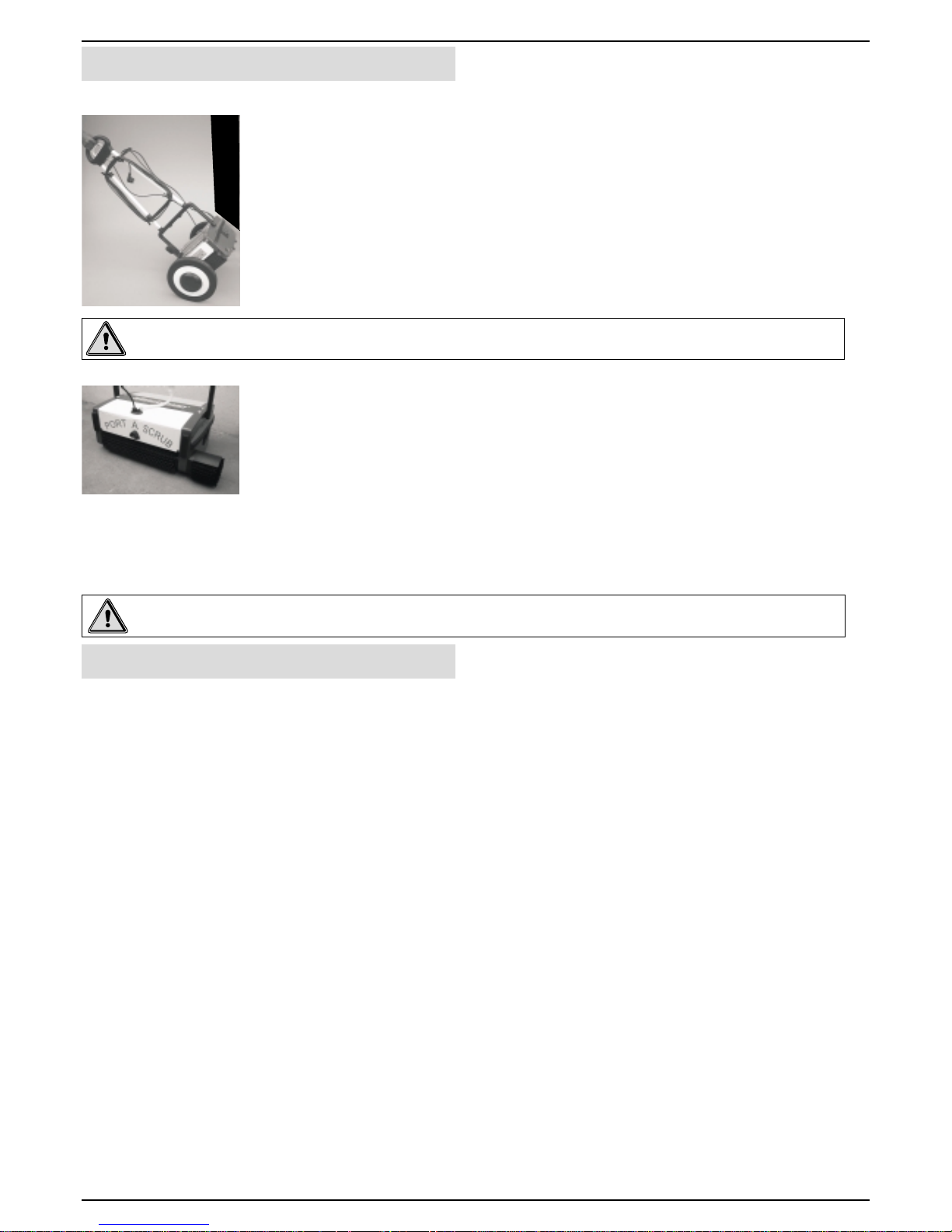
Transporter
Side Brush
Upkeep of your PORT A SCRUB
Togetthemaximum life ofthemachineensurethe following.
Regularlyinspect sheath, plugandcordanchoragefor damage orlooseconnection.
For maximum life wash the brushes regularly.Ensure machine is in Transportmode when not in use. Store
additionalbrushes in a verticalposition to avoidbending of bristles. Checkfor permanent bending ofbristles
in a particular direction. This may occur if the machine is operated for several days without removing the
brushes, which is not recommended. If this occurs, reverse the brush so that the bent bristles are
automaticallystraightened.
This may wear out after years of use. If this occurs the water collection performance will decrease. It should
bereplaced by anauthorizedServiceAgent.
The filter prevents clogging of the spray nozzle and should be periodically cleaned. Use pressurized air/
waterfor cleaning.
Ifthe spray ofthe nozzle becomeblocked, slide thenozzle cover offandremove nozzle washin clean water
andclean using apinandrefit.
· Supplycord
Brushes
WiperBlade
Solutionfeed filter
Nozzlemaintenance
·
·
·
·
9
Warning!Emptyallliquidfrom the machinebeforeusingthetransporter.
Thesimply fitted trolleyprovidesforeaseof movement whentransportingthemachine.
Installing the Transporter
1.With the machine handle in the upright position place the transporter centrally
alongside the machine.
2.By holding the machine firmly, strap the velcro with the machine to fix the transporter.
3.Ensure that the velcro strap properly wrapped around the bottom handle.
4.Now the transporter is ready to use. The machine can then be maneuvered easily
whilst holding the top handle.
To wash the edges, the side brush shall be used. Switch off and unplug the machine
beforefitting the sidebrush.
1.Remove the frontbrushandbrushshaft.
2.Fix the shieldassemblyandscrewit into thesideplateandtighten.
3.Insertthe side brushthroughtheshieldand mainbrush.
Fittingthe side brush
Usingthe side brush
1.Tiltthemachine at an angle move forward.This way,thedirty water thrown bythe sidebrush will becollected by
therear brush.
2.Use side brushonlyforwashingthe edges.
Page 10

10
32
25
24
105
116
116a
11
115b
19
49
84
83
19
53
9
7
87
20
88
80
114
10
19
19
7
28
115a
115b
11
19
1
43
59
42
73
13
V8
10
34
92
115
63
V7
19
111
93
62
212
2
77
46
Page 11

Housing-Drive Side
Spare Parts Manual
Ref.
No
Part
No
Description
Size
Qty
11
1 925032 CSK SCREW M4x10 4
2 925003 CRPH SCREW M3x6 6
7 925051 CSK SCREW M6x14 3
9 925114 ALLEN SCREW M6x10 2
10 925027 ALLEN SCREW M6x16 7
11 925031 ALLEN SCREW M6x20 2
13 925033 WASHER 4.2x12x1.6 4
19 925056 BEARING 6003 2RS 9
20 925062 BEARING 608 2Z 1
24 925001 BELT 500 5 M 1
25 925002 BELT 425 5 M 1
28 925012 WASHER 2
32 925018 BUMPER 1
34 925026 BUMPER 1
42 925047 BRUSH SLIDER 1
43 925048 SLIDER HOUSING 1
46 925054 SEAL 2
49 925064 PINION 1
53 925073 DRUM SPROCKET 1
59 925092 PIN 1
62 925099 O' RING 2
63 925102 SHIELD 1
73 925186 SELF TAPPING SCREW 4
77 925130 CAP 2
80 925227 GEAR HOUSING 1
83 925181 HOUSING SPROCKET 1
84 925182 SEAL 1
87 925193 GEAR – LH 1
88 925194 GEAR - RH 1
92 925219 SHIELD 2
93 925220 ROLLER 2
105 925249 BUMPER SLEEVE 3
111 925804 BRUSH SPROCKET 2
114 925813 GEAR SPROCKET 2
115 925815 IDLER ASSY 1
115a 925075 SPROCKET 1
115b 925046 HUB 2
116 925816 IDLER ASSY 1
116a 925061 SLEEVE 1
212 925221 STUB AXLE 1
V7 925150 DRIVE HOUSING 1
V8 925319 COVER 1
Page 12

V2
V3
133
75
10
94b
94a
94
129
86
131
132
89
21
72
73
6
81
16
100
39
90
12
95
96
99
98
93
62
212
33
188
68
17
106
15
242
18
9
19
79
2
77
46
32
105
V5
9
10
V8
34
13
73
58
59
43
1
92
63
Page 13

Housing-Idle Side
Ref.
No
Part
No
Description
Size
Qty
13
1 925032 CSK SCREW M4x10 4
2 925003 CRPH SCREW M3x6 6
6 925039 CSK SCREW M5x25 2
9 925114 ALLEN SCREW M6x10 2
10 925027 ALLEN SCREW M6x16 5
13 925033 WASHER 4.2x12x1.6 4
15 925100 WASHER 6.4x12x1.6 1
16 925151 WASHER 9x17x1.6 1
17 925110 SPRING WASHER M6 1
18 925059 TOOTHED WASHER M6 1
19 925056 BEARING 6003 2RS 2
21 925063 WIRE TIE 3
32 925018 BUMPER 1
33 925019 BUSH 2
34 925026 BUMPER 1
39 925040 STUB AXLE 1
43 925048 SLIDER HOUSING 1
46 925054 SEAL 2
58 925083 TRANSPORTSLIDER 1
59 925092 PIN 1
62 925099 O' RING 2
63 925102 SHIELD 1
68 925109 FAN COVER 1
72 925116 GROMMET 2
73 925186 SELF TAPPING SCREW 6
75 925124 CAP 1
77 925130 CAP 2
79 925147 STOPPER 1
81 925500 PEDAL 1
86 925192 NUT 2
89 925199 CONNECTOR 1
90 925200 SWITCH 2
92 925219 SHIELD 2
93 925220 ROLLER 2
94 925529 SOCKET ASSY 1
94a 925074 SOCKET 1
94b 925076 TERMINAL 3
95 925501 CABLE 1
96 925502 CABLE 1
98 925504 CABLE 1
99 925505 CABLE 1
Page 14

V2
V3
133
75
10
94b
94a
94
129
86
131
132
89
72
73
6
81
16
100
39
90
14
95
96
99
98
21
93
62
212
33
188
68
17
106
15
242
18
9
19
79
2
77
46
32
105
V5
9
10
V8
34
13
73
58
59
43
1
92
63
Page 15

Housing-Idle Side
Ref.
No
Part
No
Description
Size
Qty
15
100 925152 SPRING-PEDAL
1
105 925249 BUMPER SLEEVE
3
106 925161 CSK SCREW M4x8
1
129 925015 LEVER SWITCH ACT
1
131 925041 INSULATION TOP
1
132 925044 INSULATION BOTTOM
1
133 925101 NUT
1
188 925207 SLEEVE TIE ROD
3
212 925221 STUB AXLE
1
242 925347 CLAMP WIRE
1
V2 925534 CAPACITOR (M12230) 1
V3 925173 CIRCUIT BREAKER (M12110) 1
925166 CIRCUIT BREAKER (M12230) 1
V5 925153 IDLE HOUSING (M12110) 1
925154 IDLE HOUSING (M12230) 1
V8 925319 COVER 1
Page 16

245
16
165
187
184
1
183
M12110
185
247
180
159
1
106
245
168
106
181
164
72
246
244
V2
165
155
101
176
V9
169
186
182
163
167
158
154
174
173
121
123
123a
122b
162
170
102
72
175
177
248
Page 17

Pump Housing
Ref.
No
Part
No
Description
Size
Qty
17
1 925032 CSK SCREW M4x10 5
72 925116 GROMMET 2
101 925160 O-RING-PUMP 1
102 925077 FILTER 1
106 925161 CSK SCREW M4x8 8
121 925832 DIRTY WATER TANK 1
122b 925162 LID PAD 2
123 925836 LID-DIRTY WATER 1
123a 925132 LID-DIRTY WATER 1
154 925128 HOSE-275(10.8) 1
155 925163 INSULATION 1
158 925164 HOSE CLIP 1
159 925165 NOZZLE 1
162 925167 BOOT 1
163 925168 SCREW M3X30 2
164 925169 HEX NUT M3 2
165 925170 HEX NUT M4 3
167 925187 SWITCH 2
168 925204 STRIP LID 2
169 925224 EXTENSION BUSH 1
170 925233 HOSE-165(6.5) 2
173 925261 HOSE CONNECTOR 1
174 925262 BOOT-LID 1
175 925506 CABLE 1
176 925511 ADAPTOR NOZZLE 1
177 925573 CABLE 1
180 925171 SEAL NOZZLE 1
181 925173 BASE SWITCH 1
182 925174 LEVER 1
183 925175 CLAMP 1
184 925176 SUPPORT RING 2
185 925177 PUMP HOUSING 1
186 925178 LID 1
187 925179 SPACER 1
V9 925210 PUMP (M12230) 1
for M12110
165 925170 HEX NUT M4 2
244 925011 CLAMP CAPACITOR (M12110)
1
245 925013 CSK SCREW M4x12 8
246 925016 GROMMET (M12110)
2
247 925020 PUMP HOUSING (M12110)
1
248 925021 CABLE (M12110)
1
V2 925536 CAPACITOR (M12110) 1
V9 925203 PUMP (M12110) 1
Page 18

18
119a
118a
119
64
118
76
26
4
128
120
120a
119a
82
119
29
78
41
47
76
91
26
76
113
45
Page 19

Lever and Guide Link Mechanism
Ref.
No
Part
No
Description
Size
Qty
19
4 925104 CRPH SCREW M4x12 2
26 925008 CLEVIS PIN 5
29 925014 CLEVIS PIN 1
41 925043 LINK 1
45 925053 SHIELD 8
47 925055 LEVER 2
64 925105 LEVER BUTTON 4
76 925129 CIRCLIP 6
78 925139 LINK GUIDE 1
82 925180 SPRING 1
91 925212 BUSH 1
113 925810 W HEEL 4
118 925822 LEVER ASSY 1
118a 925085 LEVER 1
119 925823 LEVER ASSY 2
119a 925086 LEVER 2
120 925824 LEVER ASSY 1
120a 925087 LEVER 1
128 925050 LEVER SWITCH 1
Page 20

20
V4
23
35
57
189
3
60
104
153
44
71
12
117
48
11
4
135
126
12
4
172
160
160a
160c
160b
179
161d
161
161c
161b
161a
152
224
231
73
229
225
73
230
65
4
52
225
227
228
66
224
226
Page 21

Handle Group
Ref.
No
Part
No
Description
Size
Qty
21
3 925058 CRPH SCREW M4x8 1
4 925104 CRPH SCREW M4x12 10
11 925031 ALLEN SCREW M6x20 2
12 925088 WASHER 6.4x18x2 4
23 925098 CABLE RETAINER 1
35 925028 CLAMP 1
44 925049 PULL HANDLE 1
48 925057 CAP 1
52 925069 BASE-CABLE HOLDER 2
57 925082 CLAMP 1
60 925096 NUT 1
65 925106 SPRING 6
66 925107 WASHER 6
71 925115 PLUG 2
73 925186 SELF TAPPING SCREW 10
104 925184 PULL CABLE-P 1
117 925818 TOP HANDLE 1
126 925103 KNOB 2
135 925089 BOTTOM HANDLE 1
152 925127 GASKET 1
153 925111 TANK-4l 1
160 925117 BASE VALVE 1
160a 925118 BASE 1
160b 925119 SEAL 1
160c 925120 CAP-VALVE 1
161 925135 VALVE 1
161a 925122 BODY-VALVE 1
161b 925540 SEAL 1
161c 925123 SPRING 1
161d 925125 CAP-SPRING 1
172 925260 PLATE 1
179 925126 NUT 1
189 925274 SLEEVE 1
224 925305 KNOB-CABLE HOLDER-II 2
225 925306 KNOB-CABLE HOLDER-I 2
226 925307 KNOB-TANK HOLDER-LH 1
227 925308 KNOB-TANK HOLDER-RH 1
228 925339 BASE-CABLE AND TANK HOLDER 2
229 925340 GUIDE 1
230 928633 PIPE-LH 1
231 928634 PIPE-RH 1
V4 925922 POWER CORD 1
Page 22

22
134
134b
134a
V6
28
7
V1
50
112
27
31
54
15
5
56
62
37
55
38
14
22
67
70
69
8
51
Page 23

Motor, Drum and Bridge Assembly
Ref.
No
Part
No
Description
Size
Qty
23
5 925136 HEX NUT M6 3
7 925051 CSK SCREW M6x14 4
8 925090 ALLEN SCREW M4x10 2
14 925080 WASHER 5.2x10x1.6 2
15 925100 WASHER 6.4x12x1.6 3
22 925084 GRUB SCREW M5x12 2
27 925009 BUSH 4
28 925012 WASHER 4
31 925017 WASHER 6
37 925037 SPRING 1
38 925038 SPRING 1
50 925065 HEX SHAFT 2
51 925068 WASHER 2
54 925078 TIE ROD 3
55 925079 SHAFT 1
56 925081 ROLLER 6
62 925099 O' RING 12
67 925108 BUSH 2
69 925112 BUSH 1
70 925113 BUSH 1
112 925808 BRUSH SHAFT 2
134 925067 DRUM ASSY 1
134a 925070 DRUM 1
134b 925071 DRUM SLEEVE 1
V1 925762 MOTOR (M12110) 1
925761 MOTOR (M12230) 1
V6 928548 BRIDGE 1
Page 24

Accessories
24
Side Brush Assy
2
3
4
5
6
1
7
6
8
8
6a
6a
6b
6c
9
1
12
10
10
11
10
3
2
5
4
Transporter
Page 25

25
Accessories
1
2
3
4
5
6
6a
6b
6c
7
8
9
10
11
12
925881
925155
925156
925157
925158
925137
925138
925140
925141
925159
925142
925143
925144
925878
925879
FRAME
CLAMP
FIXED STRIP (VELCRO)
FLEXIBLE STRIP(VELCRO)
PLATE
TYRE
BUSH-WHEEL RIM
WHEEL RIM
TYRE-MAIN WHEEL
CAP WHEEL
WASHER
CIRCLIPA17x1
CRPH SCREW M4x25
STOPPER TOP
STOPPER BOTTOM
925904-TRANSPORTER
1
1
1
1
1
2
4
2
2
2
4
2
6
1
2
SL
NO
PART NO DESCRIPTION QTY
1
2
3
4
925901
925902
925903
925908
BRUSH-STD
BRUSH-POLISHING
BRUSH-SCRUBBING
BRUSH-ESCALATOR
BRUSH
SL
NO
PART NO DESCRIPTION
1
2
3
4
5
6
SHIELD
BUSH
SHAFT
SIDE BRUSH
WASHER
ALLEN SCREW M5x20
SIDE BRUSH ASSY
DESCRIPTIONSL.
NO
QTY
925766
925172
925764
925855
925145
925146
925907
STANDARD
925766
925172
925764
925595
925145
925146
925927
ESCALATOR
1
1
1
1
1
1
Note: Since the companies policy is to continuously improve the product, these could be changed without prior notice.
Page 26

26
Page 27

27
Page 28

LIMITED WARRANTY
Minuteman International, Inc. warrants to the original purchaser/user that this product is free from defects in
workmanship and materials under normal useand service for a periodof one year from dateof purchase. In addition,
Minuteman International, Inc will, at its option, honor labor warranty claims for the first 6 months from date of sale,
provided such claims are submitted through and approved by factory authorized repair stations. Minuteman
International,Inc will,atits option,repairor replacewithoutcharge, exceptfortransportation costs,partsthatfail under
normal use and service when operated and maintained in accordance with the applicable operation and instruction
manuals.
This warranty does not apply tonormal wear,or toitems whose life is dependenton their use and care, such as belts,
cords, switches, hoses, rubber parts, electrical motor components or adjustments. Parts not manufactured by
MinutemanInternational,Inc such as engines, batteries, battery chargers, hydraulic pumps,andtiresarecoveredby
and subject to the warranties and/or guarantees of their manufacturers. Please contactMinuteman International, Inc
forprocedures inwarranty claimsagainstthese manufacturers.
Special warning to purchaser - Use of replacement filters and / or pre-filters not manufactured by Minuteman
International,Inc. orits designatedlicenseeswillvoidall warrantiesexpressedor implied.
Apotentialhealthhazardexists withoutexact originalequipmentreplacement.
Allwarranted items become the soleproperty of Minuteman International, Inc. oritsoriginal manufacturer,whichever
thecase maybe.
Minuteman International, Inc. disclaims any implied warranty, including the warranty of merchantability and the
warranty of fitness for a particular purpose. Minuteman International Inc. assumes no responsibility for any special,
incidentalorconsequentialdamages.
Thislimited warrantyisapplicable only ontheU.S.A. andCanada,and is extendedonlyto theoriginaluser / purchaser
of this product. Customers outside the U. S. A and Canada should contact their local distributor for export warranty
policies. Minuteman International Inc. is not responsible for costs or repairs performed by persons other than those
specifically authorized by Minuteman International, Inc. This warranty does not apply to damage from transportation,
alterations by unauthorized person, misuse or abuse of the equipment,use of non-compatible chemicals, or damage
toproperty,orlossofincomedue tomalfunctionsof theproduct.
Ifa difficultydevelopswiththis machine,youshouldcontactthe dealerfrom whomitwas purchased.
This warranty gives you specific legal rights, and you may have other rights, which vary from state to state. Some
states do not allow the exclusion of limitation of special, incidental or consequential damages, or limitations on how
longan impliedwarranty lasts,sotheaboveexclusions andlimitationsmaynotapply toyou.
World Headquarters
Minuteman International, Inc.
111 South Rohlwing Road
Addison, Illinois 60101
(630) 627-6900
FAX (630) 627-1130
Minuteman Canada, Inc.
2210 Drew Road,
Mississauga, Ontario
L5S 1B1
(905) 673-3222
FAX (905) 673-5161
928747
Printed in U.S.A
 Loading...