

Page 1

Instruction Manual
Minuteman KS 28 B (6403.21)
Minuteman KS 28 G (6403.xx)
Page 2

Introduction
Preface
Introduction
Dear customer,
We hope that the excellent qualities of
the machine justify the faith you have
shown in us by purchasing the product.
Your safety, and that of others, is dependent on your ability to control the
machine. Please read this translation of
the original manual before using the
machine for the first time, act according
to the information contained and keep it
in a safe place for future reference or
subsequent owners. In order to ensure
that you can work with the machine
safely, please read the chapter on safety before starting it up.
The operating manual contains all the
important information you need to operate, maintain and service the machine.
Sections of this operating manual which
are relevant to safety are marked by the
hazard label. If you have any questions
with regard to the machine or operating
manual, you can contact your Minuteman service partner at any time.
We would like to emphasize that no legal claims can be asserted in respect of
any work described in this manual. Ensure only original spare parts are used
should any repairs be necessary. Only
such original spare parts warrant that
the equipment is reliably ready to use at
all times. We reserve the right to make
technical improvements.
Valid from: March 2011
Minuteman International
14N845 U.S. Route 20
Pingree Grove, IL 60140
Telephone: (800) 323-9420
Fax: (800) 422-6933
Intended use
The Minuteman KS
operated vacuum sweeper for industrial/commercial use and serves to clean
up dry and wet waste from indoor and
outdoor areas such as production
plants, warehouses, car parks, parking
blocks, pedestrian precincts, market
squares, railway stations and filling stations. The Minuteman KS 28 can clean
all types of industrial floor, concrete, asphalt and tar, paving and interlocking
stone paving. It is not permitted for use
on public roads with motor traffic. The
Minuteman KS 28
with a carpet kit so it can also be used
to clean dry waste from carpets.
Any use beyond this is regarded as improper use. The manufacturer is not
considered liable for any damage resulting from improper use; the user is
solely responsible for all the risks.
Intended use also includes maintaining
and observing the operating, maintenance and repair conditions prescribed
by the manufacturer.
28 is a manually
B can be upgraded
2
Page 3

Introduction
The Minuteman KS 28 may only be operated, serviced and repaired by personnel who are familiar with the work involved and are aware of the risks.
Based on the conception, design and
construction of the model introduced
onto the market by us, the machine
complies with the applicable basic safety and health requirements stipulated in
the EC directives (refer to the Declaration of Conformity). The EC Declaration
of Conformity is no longer considered
valid in the event of modifications to the
machine not authorized by us. The
manufacturer is not deemed liable for
any damage resulting from unauthorized modifications to the machine.
Information on the warranty
As a fundamental rule, the regulations
in the purchase agreement apply.
There are no rights to claims for compensation under the terms of warranty
when the damage is a result of failure to
observe the stipulations concerning
service and maintenance. Maintenance
work must be completed by an authorized Minuteman service center and
confirmed in the “maintenance logbook”; this serves as proof of rights to
claims under the terms of warranty.
The following are excluded from the
terms of warranty: normal wear and tear
and damage caused by overuse, defective fuses, improper handling or unauthorized modifications. Claims under
the terms of warranty are also annulled
when damage occurs to the machine as
the result of the use of parts and accessories not explicitly approved by us or to
failure to observe maintenance procedures.
Handover of the machine
Inspect the vehicle immediately on delivery for signs of transport damage.
Replacement will be made when confirmation is provided immediately by the
freight carrier with regard to the damage and the damage report is sent to
our authorized sales partner together
with the consignment note.
Disposing of the machine
Render the machine inoperable. It must
not represent a source of risks to children.
Dispose of the machine in accordance
with the applicable local regulations.
For further information on disposal and
recycling, contact the authorized Minuteman dealer where you purchased
the machine.
Disposing of batteries
Used batteries with the recycling symbol contain reusable commodities.
However, the heavy metals contained
also represent a major risk to human
health and to the environment. Never
open or damage batteries. Never touch,
inhale or swallow the content matter of
batteries. Health hazard! Do not allow
batteries to pollute the environment.
There is a risk of contaminating the
ground and water! In accordance with
the symbol with the crossed out bin,
these batteries must not be disposed of
in domestic waste. The return and recycling of old batteries must be agreed on
with the authorized Minuteman dealer
in accordance with national requirements.
3
Page 4

Contents
Introduction . . . . . . . . . . . . . 2
Preface. . . . . . . . . . . . . . . . . . 2
Intended use. . . . . . . . . . . . . . 2
Information on the warranty . . 3
Handover of the machine. . . . 3
Disposing of the machine. . . . 3
Disposing of batteries. . . . . . . 3
1 Safety Information . . . . . . . . 6
1.1 Safety and warning symbols . 6
1.2 General information . . . . . . . . 7
1.3 Operating information. . . . . . . 7
1.4 Maintenance information . . . . 8
1.5 Particular risks . . . . . . . . . . . . 9
1.6 Environmental protection . . . . 9
1.7 Labels on the machine. . . . . 10
2 Starting Up . . . . . . . . . . . . . 14
2.1 Before starting up
for the first time. . . . . . . . . . . 14
2.1.1 Unpacking . . . . . . . . . . . . . . 14
2.1.2 Refueling the engine
(only Minuteman KS 28 G). . 15
2.1.3 Checking the oil level
(only Minuteman KS 28 G). . 15
2.1.4 Connecting the battery
(only Minuteman KS 28 B) . . 15
2.1.5 Initial battery charge
(only Minuteman KS 28 B) . . 15
2.1.6 Instruction. . . . . . . . . . . . . . . 16
2.2 Before starting up each day . 16
3 Operation . . . . . . . . . . . . . . 17
3.1 Method of operation . . . . . . . 17
3.2 Operating and
indicator elements . . . . . . . . 18
3.2.1 Operating elements . . . . . . . 18
3.2.2 Operating panel . . . . . . . . . . 22
3.3 Operation . . . . . . . . . . . . . . . 24
3.3.1 Switching on. . . . . . . . . . . . . 24
3.3.2 Accelerating . . . . . . . . . . . . . 25
3.3.3 Stopping. . . . . . . . . . . . . . . . 25
3.3.4 Vacuumsweeping. . . . . . . . . 25
3.3.5 Switching off. . . . . . . . . . . . . 26
3.3.6 After finishing work. . . . . . . . 27
3.3.7 Loading and transportation. . 27
3.4 Function faults . . . . . . . . . . . 28
3.5 Options. . . . . . . . . . . . . . . . . 28
4 Technical Data . . . . . . . . . . 29
4
Page 5

Contents
5 Maintenance
and Service. . . . . . . . . . . . . 31
5.1 Minuteman system
maintenance. . . . . . . . . . . . . 31
5.2 Maintenance report . . . . . . . 32
5.3 Maintenance Plan. . . . . . . . . 33
5.4 Engine . . . . . . . . . . . . . . . . . 36
5.4.1 Checking the
engine oil level . . . . . . . . . . . 37
5.4.2 Refilling engine oil . . . . . . . . 37
5.4.3 Changing/Draining
the engine oil change. . . . . . 37
5.4.4 Disassembling the air filter. . 38
5.4.5 Cleaning the air filter . . . . . . 38
5.4.6 Installing the air filter . . . . . . 38
5.5 Battery system . . . . . . . . . . . 39
5.5.1 Charging battery. . . . . . . . . . 40
5.5.2 Total discharge signal
transducer (TSG) . . . . . . . . . 40
5.5.3 Servicing the drive batteries. 40
5.5.4 Removing battery. . . . . . . . . 40
5.5.5 Inserting batteries. . . . . . . . . 41
5.5.6 Disposing of batteries. . . . . . 41
5.6 Drives. . . . . . . . . . . . . . . . . . 42
5.6.1 Adjusting the drive belt. . . . . 43
5.7 Side brush . . . . . . . . . . . . . . 45
5.7.1 Side brush wear,
readjustment. . . . . . . . . . . . . 46
5.7.2 Changing the side brush . . . 46
5.8 Rotary brush. . . . . . . . . . . . . 47
5.8.1 Cleaning the brush space. . . 48
5.8.2 Changing the rotary brush . . 48
5.8.3 Setting
the sweeping pattern . . . . . . 49
5.8.4 Changing
the sealing strips . . . . . . . . . 49
5.9 Dirt hopper . . . . . . . . . . . . . . 52
5.9.1 Removing the dirt hopper. . . 53
5.9.2 Emptying the dirt hopper . . . 53
5.9.3 Inserting the dirt hopper . . . . 53
5.9.4 Changing the seals. . . . . . . . 53
5.10 Dust vacuum . . . . . . . . . . . . 54
5.10.1 Clearing dust deposits
from panel air filter
during operation . . . . . . . . . . 55
5.10.2 Removing
the panel air filter . . . . . . . . . 55
5.10.3 Cleaning the
panel air filter thoroughly . . . 55
5.10.4 Replacing
the sealing strips . . . . . . . . . 55
5.10.5 Inserting panel air filters. . . . 56
5.10.6 Checking
the suction turbine . . . . . . . . 56
5.10.7 Checking the filter
system for leaks . . . . . . . . . . 56
5.11 Special equipment . . . . . . . . 57
Warranty . . . . . . . . . . . . . . . 58
5
Page 6
Safety Information
1 Safety Information
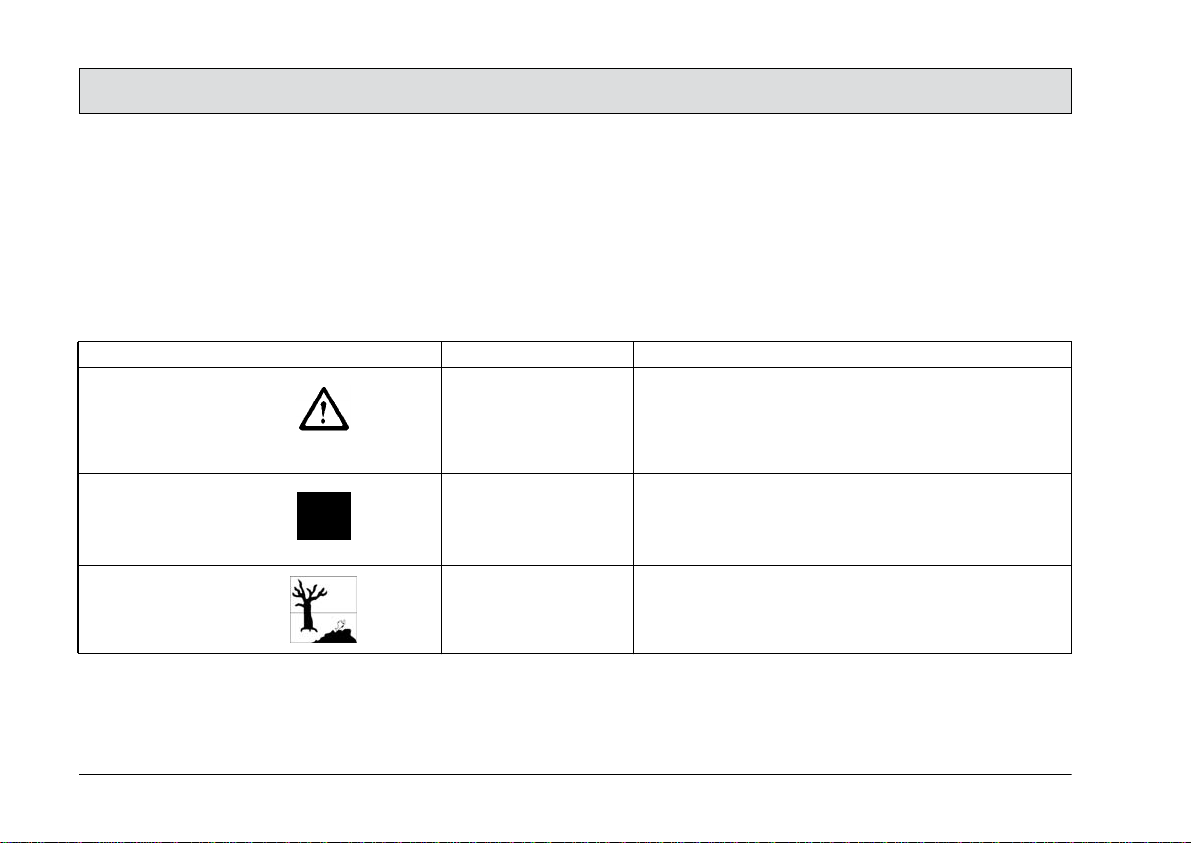
1.1 Safety and warning symbols
The following warning symbols appear
in the operating manual in those sections in which your safety, the safety of
the machine and environment could be
affected:
Symbol Damage to ... Definition
Safety information persons
or property
Note the machine Important information on handling the machine to
Risk to environment the environment Risks to the environment through using substances
6
Safety symbol to indicate dangerous situations arising
through failure to follow instructions or prescribed work
procedures precisely or through ignoring them altogether.
maintain its functioning ability.
which represent a risk to health and the environment.
Page 7

Safety Information
1.2 General information
• In addition to the information provided in this operating manual, all the
legally applicable health and safety
provisions must be observed.
• Before starting up the machine for
the first time, read the operating
manual supplied with it thoroughly as
well as any separate manuals provided with additional or attachment
devices and observe all the information during work.
• The equipment may only be operated, serviced and repaired by personnel trained by Minuteman technical
experts.
• Particular attention should be paid to
the information regarding safety.
Technical expertise is the key to preventing errors when operating the
machine and ensuring trouble-free
operation.
• The operating manual must always
be kept at the operating location of
the machine and, as a result, should
kept in a safe place on the equipment.
• If the equipment is sold or rented out,
these documents should be transferred to the new owner/operator.
The transfer should be confirmed!
• The warning labels attached to the
machine provide important information concerning safe operation.
Illegible or missing labels must be replaced by new ones.
• For reasons of safety, always use
original spare parts.
1.3 Operating information
• The machine is not suitable for clearing up fluids, dust or substances
which represent a health hazard, are
flammable or explosive. No burning
items may be cleared up, e.g. glowing cigarettes. In addition, it is forbidden to clean up wood dust, e.g.
beech and oak dust - health hazard!
• When the machine is in vacuumsweeping mode, it must not be driven through puddles of water.
• Before starting the machine up for
the first time, the battery to be used
must be fully charged, properly, by
implementing the initial battery
charge routine (only Minuteman
KS 28 B). Minuteman assumes no liability for damage to the battery
caused by a fault when the battery is
charged for the first time.
• The machine together with the working equipment must be checked in
terms of proper condition and operational safety each time prior to use.
Clear any faults immediately! The
machine must not be used when not
in a sound condition.
• Only start the machine when the
hood is closed and locked and the lever of the shaking device has been
pushed in.
• All protective devices must be properly fitted before the machine can be
taken into operation.
• Before starting work, the operator
must be fully familiar with all adjustment, operating and control elements as well as their respective
function! It is too late to do this when
the machine is actually in operation!
• Always wear heavy duty, non-slip
footwear when working with the machine.
• The machine may only be used on
those surfaces which have been approved by the contractor or person
appointed by him.
• The manner of driving must be
adapted to the local conditions.
• It is forbidden to use the machine in
7
Page 8

Safety Information
potentially explosive atmospheres.
• Do not let the engine run indoors!
Risk of poisoning (only Minuteman
KS 28 G)! Ensure sufficient ventilation when working indoors.
• When using the machine, pay strict
attention to any persons in the close
vicinity.
• Pay attention to hot parts of the engine, risk of burns.
• It is prohibited to transport passengers.
• Accelerate the machine immediately
after switching on the rotary brush,
otherwise imprints of the brush could
be produced on the floor.
• Never leave the machine unattended
as long as the engine is running.
• Remove the ignition key to prevent
unauthorized use of the machine.
• Never leave batteries in a discharged state but recharge them as
soon as possible (only Minuteman
KS 28 B).
• When transporting the machine,
switch the engine off and raise the
side brush.
• The Minuteman KS 28 can be used
on surfaces with a maximum gradient of 2%.
• Steps or curbs up to a maximum of
1.6 in can be driven over.
• It is forbidden to manipulate switches
and safety equipment.
1.4 Maintenance information
• The maintenance work and maintenance intervals prescribed in the operating manual must be adhered to.
• Operating personnel must complete
the necessary daily and weekly
maintenance work. All other maintenance work must be completed at
your nearest Minuteman service
center.
• The machine must be inspected by a
recognized technical expert in respect of operational safety, within
the terms of the applicable accident
prevention laws, at reasonable intervals (we recommend at least once a
year) and following modification or
repairs.
• Spare parts must comply with the
minimum technical requirements
stipulated by the manufacturer! This
is ensured by the use of original
spare parts.
• The machine must be switched off
prior to cleaning or servicing it or to
replacing parts.
• Suitable tools must be used for
cleaning and maintenance work.
• When working with the hood raised,
it must be opened up fully to prevent
it from accidentally dropping or slamming shut.
• When working on the electrical system, always disconnect the battery
cable (only Minuteman KS 28 B).
• Battery may only be handled and
changed by properly skilled maintenance personnel (only Minuteman
KS 28 B).
• Pay attention that the insulation of
the charger cable is not damaged
and cannot be damaged during the
charging process. The cable must
not chafe against anything. In the
case of defective insulation, do not
use the on-board charger (only Minuteman KS 28 B).
• Check the exhaust system at regular
intervals (only Minuteman KS 28 G).
• It is prohibited to clean the machine
with a pressure washer or steam
blaster.
• It is prohibited to use aggressive and
corrosive cleaning agents.
• Allow the machine to dry properly af-
8
Page 9

Safety Information
ter being cleaned.
• Do not store the machine with liquid
remaining in the tanks especially
during times of inactivity e.g. over
the weekend.
• Do not carry out any welding, drilling,
sawing or grinding work on the frame
sections. Damaged parts may only
be changed at an authorized Minuteman service center.
1.5 Particular risks
Electric system
• In case of malfunction of the electricsystem, shut the machine down immediately and have it serviced.
• Only qualified personnel are authorised to work on the electrical installations and only according to electrotechnical rules.
• Inspect/check the electrical equipment of the machine at regular intervalls. Clear up any defects immediately, such as loose connections or
damaged cables.
Refueling
(only Minuteman KS 28 G)
• Take the utmost care when handling
fuel: Increased risk of fire! Never refuel near open flames or incendiary
sparks! Never smoke when refueling!
• Never refuel indoors!
• Before refueling, switch off the engine and remove the ignition key.
• Wipe up spilled fuel immediately!
Batteries
(only Minuteman KS 28 B)
• Follow the operating instructions of
the battery manufacturer.
• To prevent creeping currents, always keep the batteries clean and
dry, protect from soiling such as by
metal dust.
• Never lay any metallic objects or
tools on batteries. Risk of short circuit and deflagration!
• When charging the batteries, there
must be sufficient ventilation in the
charging area. Otherwise, there is a
risk of explosion!
• Batteries must not be connected or
disconnected when conducting electricity.
• Wash your hands thoroughly after
working on batteries.
Health hazard
• The shaking device for cleaning the
panel air filter may only be actuated
when the dirt hoppers are in the ma-
chine and have been raised.
• It is forbidden to eat, drink and
smoke in battery charging rooms.
Safety equipment
• Never operate the Minuteman KS 28
without the hood being closed and
locked (safety equipment)!
• Do not open the hood when the engine is running!
1.6 Environmental protection
• Sufficient factual knowledge is required in order to use substances
which could represent a risk to
health and the environment, e.g oil
and lubricants.
• Observe the applicable laws and local regulations when disposing of
waste and cleaning agents.
• Observe the applicable laws and local regulations when disposing of
waste oil (only Minuteman KS 28 G).
• Used batteries with the recycling
symbol must not be disposed of in
household waste, refer to Section
Disposing of batteries.
9
Page 10
Safety Information
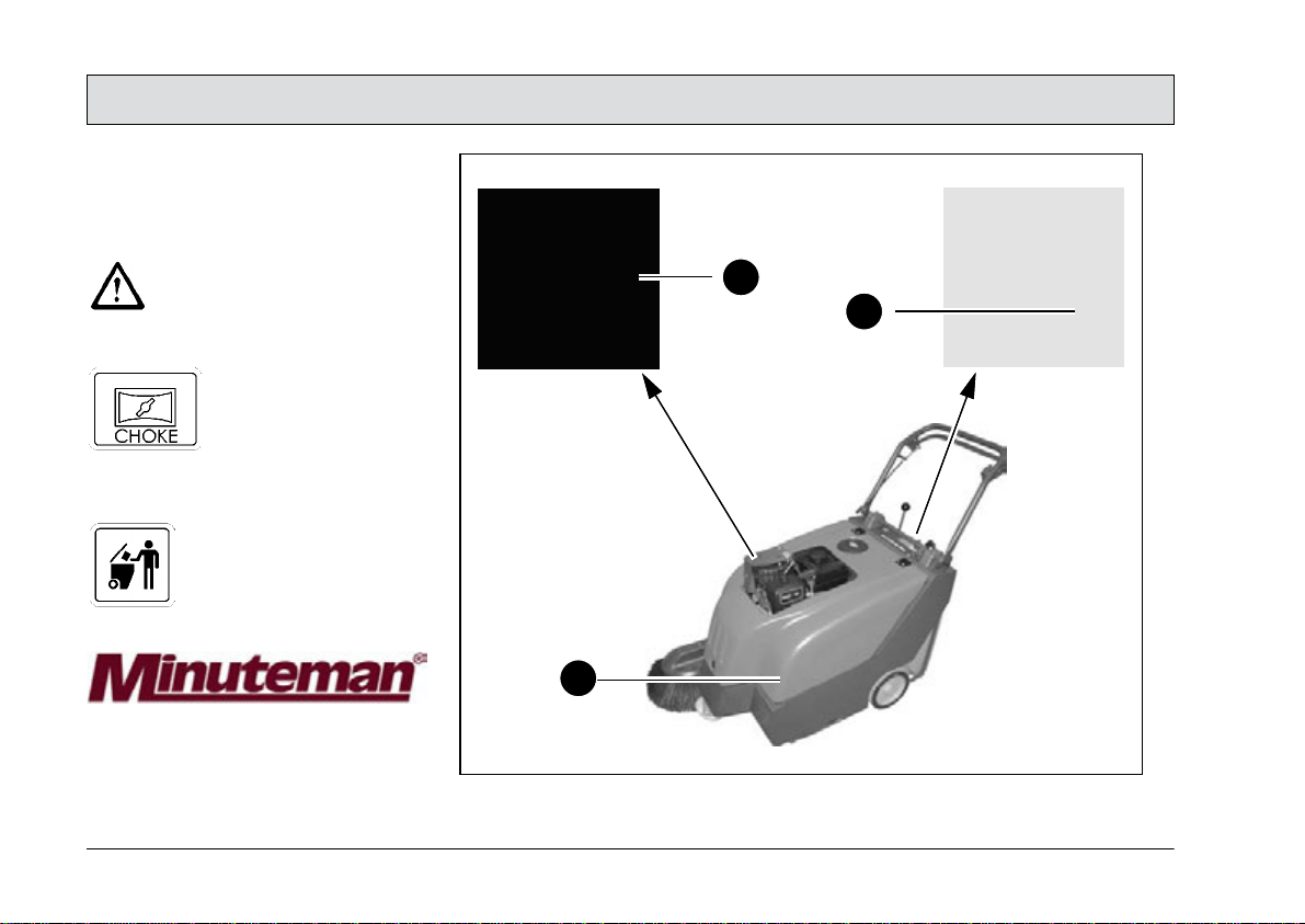
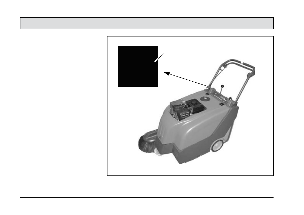
1.7 Labels on the machine
The following safety and warning labels
are attached to the machine where easily legible.
Missing or illegible labels must
be replaced immediately.
Choke (Fig. 1/1)
(only Minuteman KS 28 G)
Lock, dirt hopper
(Fig. 1/2)
Company logo (Fig. 1/3)
1
2
3
10
Fig. 1
Page 11
Safety Information
6
1
5
4
3
2
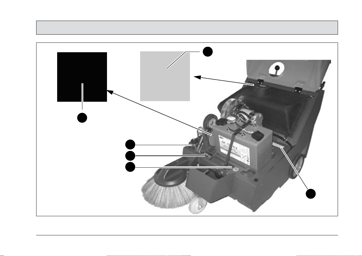
Fig. 2
11
Page 12

Safety Information
Bypass flap (Fig. 2/1)
Only use maintenance-free batteries
(Fig. 2/2)
(only Minuteman KS 28 B)
Wear compensator for rotary brush
(Fig. 2/3)
Rating plate (Fig. 2/4)
Wear compensator for side brush
(Fig. 2/5)
Oil label (Fig. 2/6)
(only Minuteman KS 28 G)
Engine oil, only use SAE 15 W 40.
12
Page 13
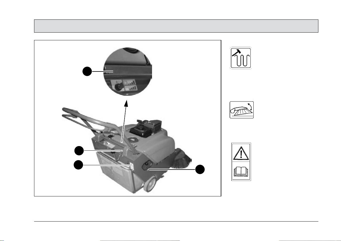
Safety Information
Shaking device (Fig. 3/1)
Fig. 3
2
Type of machine (Fig. 3/2)
Minuteman KS 28
Lower/Raise side brush (Fig. 3/3)
Read and observe the operating
manual (Fig. 3/4)
3
4
1
13
Page 14
Starting Up
2 Starting Up
2.1 Before starting up for the first time
2.1.1 Unpacking
Remove the packaging, open the fastening straps and take the Minuteman
KS 28 from the pallet. For reasons of
packaging, the handlebar of the Minuteman KS 28 is pivoted forwards. First of
all, pivot the handlebar to its operating
position.
Pivoting the handlebar to its operating position
1. Loosen the wing bolts (Fig. 4/1) on
the right and left sides of the handle
bar (Fig. 4/2) a few revolutions until
the handlebar (Fig. 4/2) can be
straightened up.
2. Pivot the handlebar (Fig. 4/2) to-
wards the rear and set it to a height
convenient for the user.
3. Tighten the wing bolts (Fig. 4/1) on
the right and left sides of the handlebar (Fig. 4/2).
2
1
-
14
Fig. 4
Page 15
Starting Up
2.1.2 Refueling the engine (only Minuteman KS 28 G)
Unscrew the fuel tank cap
(Fig. 7/5) and fill approx. 2.5 l gasoline.
Screw the fuel tank cap back on.
Only refuel the machine when
the engine has cooled down.
Otherwise, any spilled gasoline can evaporate if it lands on
hot machine parts. Health hazard through inhaling vapors!
Refueling must not be carried
out in closed rooms.
Refueling may only be carried
out when the engine is
switched off! Remove the ignition key.
It is forbidden to smoke or use
fire when refueling or working
on or near components containing fuel.
Wipe up any spilled fuel!
Wipe up spilled fuel with a cloth
and dispose of the cloth according to the applicable environmental laws.
2.1.3 Checking the oil level (only Minuteman KS 28 G)
Engine oil is filled at the factory. As a
precaution, however, check the oil level
again on site, refer to Section 5.4.1.
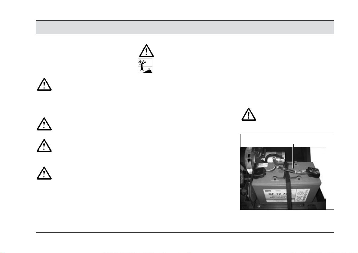
2.1.4 Connecting the battery (only Minuteman KS 28 B)
Before starting up for the first time, connect the positive cable of the device as
illustrated in Figure 5 to the positive
pole (Fig. 5/1) of the battery in the device.
2.1.5 Initial battery charge (only Minuteman KS 28 B)
Before starting up the machine for the
first time, the batteries used must be fully charged by completing the initial battery charge, refer to Section 5.5.1. Minuteman assumes no liability for damage
to the battery resulting from failing to
carry out the initial battery charge properly.
Risk of explosion! When charging the battery, there must be
sufficient ventilation in the
charging area.
1
Fig. 5
15
Page 16

Starting Up
2.1.6 Instruction
Operators must receive instruction before putting the machine into service.
Only technicians from your local, authorized Minuteman dealer are allowed to
provide initial instruction on how to use
the machine. The manufacturing plant
notifies the dealer immediately after delivering the machine and the dealer will
contact you to arrange a date for providing the initial instruction.
2.2 Before starting up each day
Carry out the following checks before
starting the machine:
1. Check the parking space for signs of
leaks.
2. Only Minuteman KS 28 G:
Check the engine oil level with the
dipstick and refill, if necessary; refer
to Section 5.4.2.
3. Only Minuteman KS 28 G:
Check the fuel supply and refill fuel,
if necessary, refer to refer to Section 2.1.2.
4. Only Minuteman KS 28 B:
Check the charge status of the battery and recharge, if necessary.
5. Check the fill level of the dirt hopper
and empty them, if necessary.
6. Check the levels of wear on the rotary brush and side brush.
7. Check the ergonomic position of the
handlebar and readjust it, if necessary.
16
Page 17
Operation
3 Operation
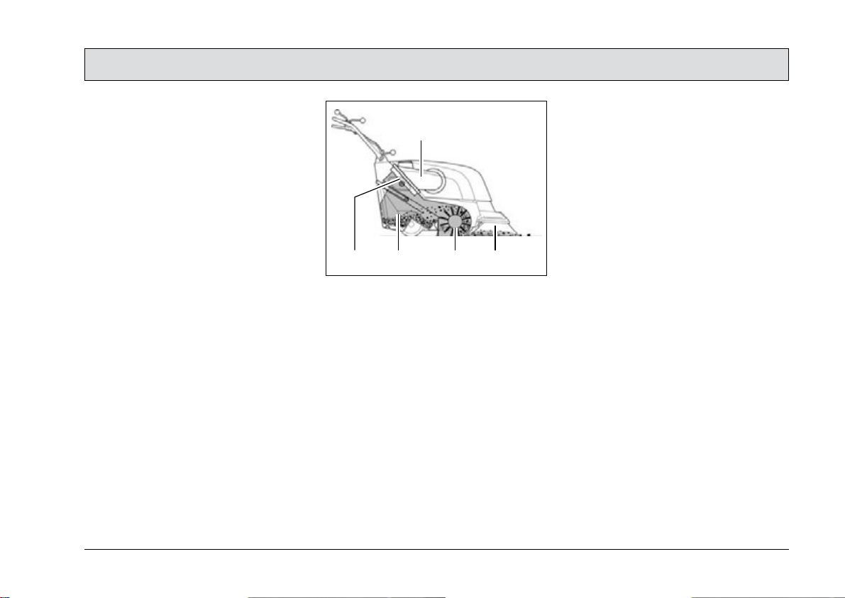
3.1 Method of operation
The Minuteman KS 28 is a manually
operated vacuum sweeper machine
with a drive for the dry cleaning of hard
floors and carpets.
The side brush (Fig. 6/4), located on the
right-hand side of the machine, sweeps
the dirt away from corners and edges
into the path of the rotary brush
(Fig.
6/3). The rotary brush (Fig. 6/3)
sweeps the dirt into the dirt hopper
(Fig. 6/2) using the overhead throw
method. The particulate matter (depicted gray in Fig. 6) is forced against the
panel air filter (Fig. 6/1) by the suction
turbine (Fig. 6/5) and filtered out there.
Only dust-free air is fed back into the
ambient air.
Fig. 6
1 Panel air filter
2 Dirt hoppers
3 Rotary brush
4 Side brushes
5
Suction turbine
5
Minuteman KS 28 G
The Minuteman KS 28 G is equipped
with a gasoline engine and is filled with
approx. 2.5 l gasoline.
Minuteman KS 28 B
To charge the battery, the Minuteman
KS 28 B is
ing, fully automatic on-board charger.
To protect the battery against total discharge, the Minuteman KS 28 B is pro-
4321
vided with a total discharge signal
transducer (TSG) which indicates the
battery status during the charging process and discharging.
equipped with
a correspond-
17
Page 18
Operation
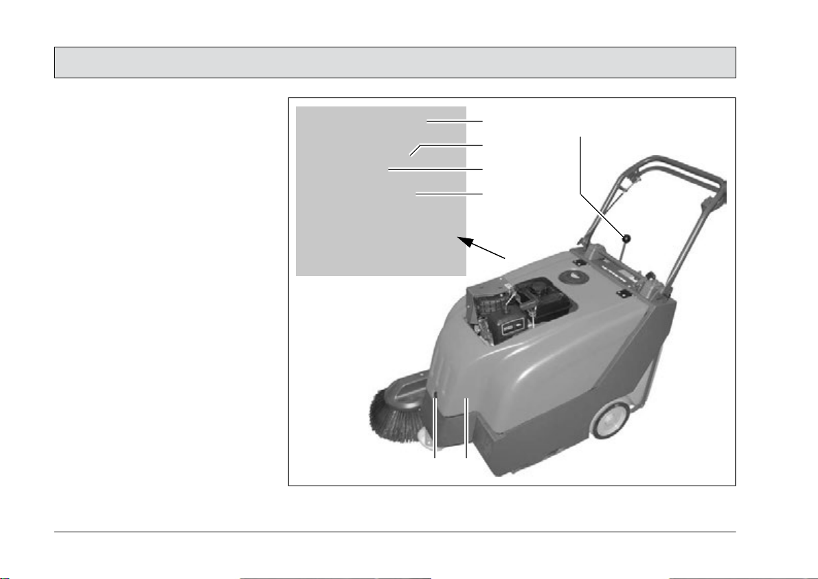
3.2 Operating and indicator elements
3.2.1 Operating elements
1 Side brush lever
2 Hood
3 Hood lock
4 Bypass flap
5
Fuel tank cap
(only Minuteman KS 28 G)
6 Choke
(only Minuteman KS 28 G)
7 Recoil starter
(only Minuteman KS 28 G)
1
5
6
7
18
342
Fig. 7
Page 19

Operation
Side brush lever (Fig. 7/1)
Use the lever to lower or raise the side
brush.
Lever forward: Side brush is lowered.
Lever to rear: Side brush is raised.
Hood with lock
(Fig. 7/2)
Only operate the machine with
the hood closed!
The hood should only be opened for
maintenance and repair work. In this
case, unlock the lock (Fig. 7/3) using a
square wrench and pivot the hood up.
Bypass flap (Fig. 7/4)
On opening the bypass flap, the vacuum operation is interrupted. If necessary, open up the bypass flap by hand.
Vacuuming should be interrupted when wet waste could
be vacuumed up.
Fuel tank cap (Fig. 7/5)
Only for Minuteman KS 28 G
line engine. The fuel tank cap closes
the fuel tank.
Choke (Fig. 7/6)
Only for Minuteman KS 28 G
line engine. The choke must be pulled
out before cold starting the engine.
Recoil starter (Fig. 7/7)
Only for Minuteman KS 28 G
line engine. The engine is then started
by pulling the recoil starter after having
set the key switch to Position 1 beforehand.
with gaso-
with gaso-
with gaso-
19
Page 20

Operation
1 Drive bar
2 Handlebar
3 Operating panel
4 Wing bolt for handlebar
5 Charger cable
6 Shaking device lever
(only Minuteman KS 28 G)
7 Dirt hopper
8 Dirt hopper lock
1 2
3
4
5
7
8
6
20
Fig. 8
Page 21

Operation
Drive bar (Fig. 8/1)
The drive bar serves to activate and deactivate the wheel drive. The drive bar
must be pulled up towards the handlebar with the fingers so that the wheel
drive operates and the machine moves
forward. If the drive bar is released, the
machine stops (safety circuit).
Handlebar (Fig. 8/2)
The machine is guide/steered via the
handlebar.
Release the drive bar when
turning sharp corners.
The two wing bolts (Fig. 8/4) serve to
adjust the handlebar to an optimal position for the user.
Operating panel (Fig. 8/3)
Refer to Section 3.2.2.
Charger cable (Fig. 8/5)
The charger cable of the Minuteman
KS 28
B is located in the recess which
also contains the shaking device lever.
Shaking device lever (Fig. 8/6)
To clean the panel air filter, pull the
shaking device lever out then push
back in again; repeat this several times.
Dirt hopper lock (Fig. 8/8)
To remove the dirt hopper, move the
locking lever to the right (when facing
the front) and, at the same time pivot
the handlebar forwards. The frame of
the dirt hoppers is lowered as a result
so that the hopper can be removed towards the rear. To lock the hopper, pull
the handlebar to the rear until the lock
audibly engages.
21
Page 22

Operation
3.2.2 Operating panel Minuteman KS 28 G
1
Fig. 9
1 Key switch
Key switch (Fig. 9/1)
The key switch serves to secure the
machine against unauthorized use.
22
Key switch positions
Position 0: Off
Position 1: On (engine ready to start)
Page 23

Operation
Minuteman KS 28 B
1 Key switch
2 Charge control indicator
3 Battery discharge status indicator
Key switch (Fig. 10/1)
The key switch serves to switch the
drive motor on and off and secure the
machine against unauthorized use.
Key switch positions
Position 0: Off
Position 1: On (engine on)
Charge control indicator (Fig. 10/2)
During the charging process, the machine electronics indicates the charge
status via four green LEDs.
The Minuteman KS 28 B can
only be charged when the key
switch is in Position 0.
As the charge level increases, it is indicated by the LEDs which light up progressively from left to right.
Fig. 10
2
1
3
23
Page 24

Operation
Flashing or individually lit LEDs
indicate an error status, also
refer to the charger operating
manual.
Battery discharge status (Fig. 10/3)
During operation, the machine electronics indicates the discharge status of the
battery by means of a red LED (left) and
three green LEDs (right).
When all three green LEDs light up, the
batteries are fully charged. As the batteries become progressively discharges, the LEDs go out in succession from
right to left. When the last green LED
goes out, the red LED starts to flash
(early warning of imminent shutdown).
After a certain time, the red LED lights
up continuously indicating the "battery
empty" status. Shortly afterwards, the
drive motor is automatically switched off
to protect the battery from a total discharge.
The machine should only be restarted
when the battery have been charged.
3.3 Operation
The Minuteman KS 28 must
not be used in domestic or office areas.
Practice all the operating steps
in a training area and only use
the machine in the areas specified for deployment when you
are familiar with all the operations.
3.3.1 Switching on
The motor must not be started
when the hood is open! Risk of
injury through belt drive and rotating fan!
Minuteman KS 28 G
Before starting the Minuteman
KS 28 G, pay attention to the
following:
1. Set the key switch (Fig. 10/1) to Position 1.
2. Pull out the choke (Fig. 7/6) in the
case of a cold start.
3. Pull the recoil starter cord (Fig. 7/7)
until the starter clutch perceptibly en-
gages (slight resistance) and then
pull the starter cord (Fig. 7/7) hard
and fast to start the engine.
4. Release the starter cord (Fig. 7/7)
and let it recoil back into the housing.
5. Then push the choke (Fig. 7/6) back
in, slowly.
If the engine does not start immediately, use the starter cord
again exactly as described
above.
The engine and sweeping functions are
activated.
Minuteman KS 28 B
Set the key switch to Position 1.
24
Page 25

Operation
3.3.2 Accelerating
When the engine is running:
1. Use your fingers to pull the drive bar
(Fig. 11/1) against the handlebar
(Fig. 11/2).
2. Steer the machine with the handlebar (Fig. 11/2) in the required direction.
12
Fig. 11
3.3.3 Stopping
1. Release the drive bar (Fig. 11/1).
The machine decelerates and
comes to a stop.
Do not park the machine on
carpets while the engine is running. Risk of fire through the
flooring overheating due to the
rotating rotary brush!
Exception: The machine is
equipped with a carpet kit (option) which automatically
switches the rotary brush off
when stopping the machine.
3.3.4 Vacuumsweeping
Ensure sufficient ventilation
when sweeping indoors!
It is forbidden to sweep up
dust which represents a health
hazard!
1. Check the machine,
refer to Section 2.2.
2. Open the bypass flap if damp waste
is to be cleared up.
3. Switch the machine on,
refer to Section 3.2.2.
The engine and sweeping functions
are activated.
Drive away immediately after
switching on the machine otherwise it is possible that marks
will be produced on the floor by
the rotating rotary brush.
25
Page 26

Operation
4. Lower the side brush: Move the lever
(Fig. 7/1) forwards.
5. Accelerating: pull the drive bar up,
refer to Section 3.2.2.
6. Drive to the ground surface to be
cleaned.
Steps and curbs up to a height
of 1.6 in can be driven over,
carefully. When driving over
thresholds, release the drive
bar and tip the machine back a
little so that the front roller can
negotiate the step.
7. Operate the shaking device occasionally, refer to Section ”Operating
the shaking device”.
8. Check the contents of the dirt hopper
regularly and empty as necessary,
refer to Section ”Emptying the dirt
hopper”.
Do not overload the dirt hopper! This can affect the stopping distance. Caution, particularly when sweeping up dirt
such as metallic chippings!
Tip out the dirt hopper from a
low height when emptying to
prevent dust swirling around! If
necessary, pay attention to the
wind direction and evade any
clouds of dust! Health hazard!
3.3.5 Switching off
Turn the key switch to Position 0.
Remove the ignition key when
leaving the machine to prevent
unauthorized use.
26
Page 27

Operation
3.3.6 After finishing work
1. Operate the shaking device.
2. Empty the dirt hopper.
3. Check the brush area for any residual waste and remove it if necessary,
refer to Section “Cleaning the brush
space“.
4. Clean the machine, if necessary.
Warning - do not clean electrical components with liquids!
Risk of electric shock!
It is not permitted to clean the
machine with a pressure washer or steam blaster.
Operating the shaking device
Push and pull the lever (Fig. 8/6) in and
out several times in succession to clean
dust from the panel air filter.
Only operate the shaking device when the engine is
switched off.
Emptying the dirt hopper
1. Move the locking lever (Fig. 8/8) to
the right (looking to the front) and, at
the same time, tip the handlebar
(Fig. 8/2) to the front.
2. Remove the dirt hopper (Fig. 12/2)
from the machine and empty it.
Carry the dirt hopper
(Fig. 12/2) by the handles
(Fig. 12/1).
21
Fig. 12
Observe the applicable laws
and local regulations when disposing of waste.
3.3.7 Loading and transportation
When loading the machine and
transporting it to its area of deployment, the side brush must
be raised.
Loading
When loading the machine, take its
weight into account, refer to Section
‘‘Technical Data‘‘.
Transporting
The machine must be properly
secured. It must not slip or tip
during transportation! Risk of
injury!
When transporting on a vehicle or trailer, the machine must be secured
against rolling away: Lash down the
machine securely at the front and rear.
27
Page 28

Operation
• Secure the machine at the front with
a strap which must be fed through
the two openings (Fig. 13/1) near the
front wheel (Fig. 13/2).
• At the rear, thread a strap around the
bottom ends of the handlebar and fix
the strap to the transporter.
1
2
Fig. 13
1
3.4 Function faults
• If the machine is overloaded, the engine speed drops.
Set the key switch to Position 0.
Check the side brush, rotary brush
and brush area for residual waste
and remove the waste, if necessary.
Ensure that there is sufficient fuel in
the tank (only Minuteman KS 28 G)
or that the battery is sufficiently
charged (only Minuteman KS 28 B).
Start the machine. If the fault occurs
again, contact a Minuteman service
center.
If the machine cannot be
switched off, pay attention to
the rotating fan when you disconnect the cable or pull out
the spark plug connector! Risk
of injury!
3.5 Options
The basic machine can be upgraded by
adding further components. The order
and spare parts numbers for these
components are provided in brackets.
• Carpet kit (6460)
By fitting the carpet kit on the Minuteman KS 28 B, the machine is converted for clearing up dry waste from
carpets.
Please refer to the spare parts
catalogue on our internet site
at http://ezparts.sysonline.com
/minuteman for accessories,
such as rotary brushes, side
brushes etc.
28
Page 29

Technical Data
4 Technical Data
Machine length in 43.3
Machine height (handlebar folded forward) in 28.4
Machine width (including side brush) in 27.2
Working width (with / without side brush) in 27.2 / 28.0
Rotary brush width in 20.1
Rotary brush diameter in 9.8
Side brush diameter in 15.8
Theoretical area coverage (with / without side brush) ft²/h 37943 / 27179
Sweeping speed mph 3.1
Dirt hopper volume gallon 9.2
Load capacity, dirt hopper (Maximum 55 lb!) lb 55
Filter surface ft² 16
Power output (Minuteman KS 28 G / Minuteman KS 28 B) hp 4.4 / 1.0
Weight, ready to use (Minuteman KS 28 G / Minuteman KS 28 B) lb 225 / 269
Climbing capacity % 2
Ambient temperature
Minuteman KS 28 G
Minuteman KS 28 B
ºF
ºF
+14 to +104
+32 to +104
29
Page 30

Technical Data
Noise emission value
The sound power level (LwA) measured in accordance with EN 60335-2-72 at
maximum working conditions:
Minuteman KS 28 G
Minuteman KS 28 B
The sound pressure level (LpA) (at the ear of the operator) measured according
to DIN IEC 60335-2-72 under normal working conditions:
Minuteman KS 28 G
Minuteman KS 28 B
Measurement inaccuracy (KpA): dB (A) 2
Vibration
The weighted effective value of acceleration, measured in accordance with DIN
EN ISO 5349, to which the upper parts of the body (hand-arm) are exposed under
normal working conditions:
Minuteman KS 28 G
Minuteman KS 28 B
dB (A)
dB (A)
dB (A)
dB (A)
m/s²
m/s²
2.6
Max. 2.5
92
85
77
68
30
Page 31

Maintenance and Service
5 Maintenance and
Service
General information
It is essential to pay attention
to the information in Chapter
"Safety Information" before
completing any service or
maintenance work!
By adhering to the maintenance work
recommended by us, you can be sure
that the machine is always ready to be
put into operation.
Maintenance and repair work necessary on a daily and weekly basis can be
carried out by an operator trained to
complete the work, all other Minuteman
system maintenance may only be completed by personnel who are correspondingly qualified and trained.
Please contact your nearest Minuteman
service center or authorized Minuteman
dealer. Failure to observe this annuls
any rights to claims under the terms of
guarantee in respect of resulting damage or consequential damage.
Always specify the serial number in the
case of inquiries and spare parts orders, refer to section 1.7 - Rating plate.
5.1 Minuteman system maintenance
The Minuteman system maintenance:
• ensures that the Minuteman ma-
chine is always ready for operation
(preventive maintenance),
• minimizes operating costs, mainte-
nance and repair costs,
• ensures the machine has a long ser-
vice life.
Minuteman system maintenance is arranged into individual modules explaining the special technical work to be carried out and prescribes the intervals at
which the work should be performed.
Parts to be replaced for the individual
maintenance tasks are defined and provided in spare parts kits.
Minuteman system maintenance,
customer
Work to be carried out by the customer
according to the service and maintenance instructions in the operating
manual (daily and weekly). The driver/operator receives proper instruction
when the machine is delivered.
Minuteman one-off system maintenance
After the first four weeks or the first
20 operating hours.
Minuteman system maintenance I
Six-monthly.
To be completed by skilled personnel
from an authorized Minuteman service
center according to the machine-specific system maintenance with spare parts
kit.
Minuteman system maintenance II
Annually.
To be completed by skilled personnel
from an authorized Minuteman service
center according to the machine-specific system maintenance with spare parts
kit - including safety check.
31
Page 32

Maintenance and Service
5.2 Maintenance report
Handover
Upgrading
Test drive
Handover to customer
Instruction
completed on:
at _________________ operating hours
Minuteman System
Maintenance
after 4 weeks
Workshop Stamp
completed on:
at _________________ operating hours
Minuteman System
Maintenance I
six-monthly
Workshop Stamp
completed on:
at _________________ operating hours
Minuteman System
Maintenance II/S
annually
Workshop Stamp
completed on:
at _________________ operating hours
Minuteman System
Maintenance I
six-monthly
Workshop Stamp
completed on:
at _________________ operating hours
Minuteman System
Maintenance I
six-monthly
Workshop Stamp
completed on:
at _________________ operating hours
32
Minuteman System
Maintenance II/S
annually
Workshop Stamp
completed on:
at _________________ operating hours
Minuteman System
Maintenance II/S
annually
Workshop Stamp
completed on:
at _________________ operating hours
Minuteman System
Maintenance I
six-monthly
Workshop Stamp
completed on:
at _________________ operating hours
Minuteman System
Maintenance I
six-monthly
Workshop Stamp
completed on:
at _________________ operating hours
Minuteman System
Maintenance II/S
annually
Workshop Stamp
completed on:
at _________________ operating hours
Minuteman System
Maintenance II/S
annually
Workshop Stamp
completed on:
at _________________ operating hours
Page 33

Maintenance and Service
5.3 Maintenance Plan Minuteman system maintenance,
customer
Activity
Check the battery charge, recharge if necessary (only Minuteman KS 28 B) oo
Check the engine oil level, refill engine oil if necessary
(only Minuteman KS 28 G)
Empty the dirt hoppers oo
Clean the brush space oo
Clean the panel air filter in the dust vacuum using the shaking device, check it for
damage and replace if necessary
Check the rotary brush and side brush; clean or replace as necessary oo
Check sealing strips (2 side aprons, 1 rear apron) for wear and clearance,
replace if necessary
Clean the air filter (only Minuteman KS 28 G) o
Check the function of the suction turbine o
Check the filter system (panel air filter) for leaks o
Check the seals on the dirt hopper o
Check the dirt hopper lock o
Check the sweeping pattern; readjust, if necessary o
Test drive and function test o
The following maintenance work must
be completed by the customer. The
maintenance intervals must be observed.
Interval
Daily Weekly
oo
oo
o
33
Page 34

Maintenance and Service
Minuteman one-off system maintenance
After the first four weeks or the first
Minuteman KS 28
G must be subject to
an engine oil change at an authorized
Minuteman service center.
20 operating hours the
Activity
after the first 4 weeks
or after 20 operating hours
Engine oil change (only Minuteman KS 28 G) o
Minuteman system maintenance I
The following maintenance work must
be completed by an authorized Minuteman service center.
Interval
Activity
Six-monthly
All the maintenance work in accordance with the weekly Minuteman system maintenance customer
Check the drive belt for signs of wear and its tension,
replace or readjust as necessary
Engine oil change (only Minuteman KS 28 G) o
or every 100 operating hours
Change the air filter (only Minuteman KS 28 G) o
Check the condition of the tires o
Test drive and function test o
Once
o
o
34
Page 35

Maintenance and Service
Minuteman system maintenance II
The following maintenance work
must be completed annually at an authorized Minuteman service center.
Activity
Interval
Annually
All maintenance work in accordance with Minuteman system maintenance I o
Check the function of the operating panel o
Check thew function of the on-board charger (only Minuteman KS 28 B) o
Check the Bowden cables for signs of wear; change, if necessary o
Check the suction turbine for signs of wear; change, if necessary o
Check the rotary brush bearing in terms of play and for signs of wear;
change, if necessary
Check the steering castor in respect of its running surface and bearing play;
change, if necessary
Check the rear wheels for bearing clearance and signs of wear of the running sur-
face; replace the wheel bearings and rear wheels, if necessary
Change the spark plug o
Clean the drive motor from carbon dust, check the carbon brushes run smoothly and
for signs of wear; change the carbon brushes, if necessary
Test drive and function test o
o
o
o
o
35
Page 36

Maintenance and Service
5.4 Engine
Before starting any maintenance and repair work, set the
key switch to Position 0 to prevent starting the machine inadvertently! Remove the ignition
key.
1 Spark plug cable
2
Screw plug with dipstick and oil fill-
ing neck
3 Oil drain bolt
4 Vessel for engine oil change
(not part of scope of delivery)
5 Fastening nut
for air filter cover
Air filter cover
6
7 Air filter
8 Fastening nut for air filter
9 Threaded pin
1
2
5
3
4
5
6
7
8
9
6
36
Fig. 14
Page 37

Maintenance and Service
5.4.1 Checking the engine oil level
1. Park the machine on a level piece of
ground.
2. Leave it to stand still for a time.
Do not check the engine oil level directly after the machine
has been in operation.
3. Open the hood.
4. Clean the area around the oil filling
neck (Fig. 14/2).
5. Unscrew the screw plug with dipstick
(Fig. 14/2) counterclockwise and
check the oil level. The oil level must
be in the range between FULL and
ADD.
6. If the oil level is near the ADD mark
or below, refill engine oil, refer to
Section 5.4.2.
7. If the oil level is considerably above
the FULL mark, drain off some engine oil, refer to Section 5.4.3.
8. Screw the screw plug with dipstick
(Fig. 14/2) back in, clockwise.
9. Close the hood.
5.4.2 Refilling engine oil
Only use SAE 15 W 40 engine
oil. The engine has a max. volume of 0.6 l engine oil.
1. Park the machine on a level piece of
ground.
2. Leave it to stand still for a time.
3. Open the hood.
4. Clean the area around the oil filling
neck (Fig. 14/2).
5. Turn the screw plug with dipstick
(Fig. 14/2) counterclockwise to remove it.
6. Pour the oil (SAE 15 W 40) slowly in
the oil filling neck.
7. Check the new engine oil level,
refer to Section 5.4.1.
8. Top up with more engine oil, if necessary, and check the engine oil level again.
9. Screw the screw plug with dipstick
(Fig. 14/2) back in, clockwise.
10.Close the hood.
5.4.3 Changing/Draining the engine oil change
Change the oil when the engine is warm but switched off.
1. Open the hood.
2. Position an appropriate collecting
vessel (Fig. 14/4) under the oil drain
bolt (Fig. 14/3).
3. Unscrew the oil drain bolt
(Fig. 14/3) and collect the escaping
oil in the vessel (Fig. 14/4).
4. Clean the oil drain bolt (Fig. 14/3)
with a clean cloth.
5. Remove the collecting vessel
(Fig. 14/4) and dispose of the waste
oil.
Observe the applicable laws
and local regulations when disposing of waste oil and oily
cloths.
6. Screw the oil drain bolt (Fig. 14/3)
back in.
7. Fill up with engine oil SAE 15 W 40,
refer to Section 5.4.2.
37
Page 38

Maintenance and Service
5.4.4 Disassembling the air filter
1. Open the hood.
2. Unscrew the fastening nut
(Fig. 14/5) securing the air filter cover (Fig. 14/6).
3. Remove the air filter cover
(Fig. 14/6).
4. Unscrew the fastening nut
(Fig. 14/8) securing the air filter.
5. Pull the air filter (Fig. 14/7) from the
threaded pin (Fig. 14/9).
5.4.5 Cleaning the air filter
1. Disassemble the air filter,
refer to Section 5.4.4.
2. Beat the air filter lightly on a level,
solid surface.
3. If necessary, vacuum the air filter
carefully using a vacuum cleaner.
Do not damage the filter ribs!
4. If the air filter cannot be cleaned sufficiently, replace the old air filter with
a new one.
5.4.6 Installing the air filter
1. Install the cleaned or new air filter
(Fig. 14/7) on the threaded pin
(Fig. 14/9).
2. Fix the air filter (Fig. 14/7) by screwing the fastening nut
(Fig. 14/8) for the air filter on the
threaded pin (Fig. 14/9).
3. Replace the air filter cover
(Fig. 14/6).
4. Screw the fastening nut (Fig. 14/5)
for the air filter cover (Fig. 14/6) on
the threaded pin (Fig. 14/9).
5. Close the hood.
38
Page 39

Maintenance and Service
5.5 Battery system
Only Minuteman KS 28 B.
Before starting any maintenance and repair work, set the
key switch to Position 0 to prevent starting the machine inadvertently!
Only batteries approved by
Minuteman may be used.
3
2
Batteries may only be handled
and changed by properly
skilled maintenance personnel.
Only maintenance-free batteries may be used.
1 Charger cable
2
On-board charger
(housing disassembled)
3 Operating panel
4 Connection diagram
5 Hood
Block battery
6
7 Handle
1
54
7
6
Fig. 15
39
Page 40

Maintenance and Service
5.5.1 Charging battery
Before starting the machine up
for the first time, the battery to
be used must be fully charged,
properly, by implementing the
initial battery charge routine.
Minuteman assumes no liability for damage to the battery
caused by a fault when the battery is charged for the first
time.
During operation, the battery discharge
indicator in the operating panel
(Fig.
15/3) indicates the discharge sta-
tus of the battery, refer to Section 3.2.2,
Section ”Battery discharge status
(Fig. 10/3)”. The battery must be
charged immediately the red LED lights
up. The battery (Fig. 15/6) is
using the integrated on-board charger
(Fig. 15/2):
1. Set the key switch to Position 0.
The battery cannot be charged
in Position 1.
recharged
2. Remove the charger cable
(Fig. 15/1) from the recess on the
right-hand side of the machine.
3. Plug the charger cable (Fig. 15/1) in
a 230 V power outlet.
While the battery is charging, the
charge control indicator lights up in the
operating panel (Fig. 15/3), refer to
Section 3.2.2, Section "Charge control
indicator (Fig. 10/2)".
When the charging process
has been completed, disconnect the plug from the power
outlet and return safely to the
recess.
5.5.2 Total discharge signal trans-
ducer (TSG)
The machine is equipped with a total
discharge signal transducer to protect
the battery against total discharge. The
total discharge signal transducer is integrated in the electronics.
5.5.3 Servicing the drive batteries
Never leave discharged batteries lying
around; recharge them immediately!
Notes on servicing drive batteries is also provided in supplementary sheet 88-60-2556 "Information on Drive Batteries“.
5.5.4 Removing battery
Before the Minuteman
KS 28 B is tipped for any reason, the battery must be removed!
40
Page 41

Maintenance and Service
1. Unlock the hood (Fig. 15/5) using a
square wrench and open the hood
(Fig. 15/5).
Ensure the engine has
stopped before opening the
hood. Risk of injury through
belt drive and rotating fan!
2. Disconnect the negative cable from
the battery (Fig. 15/6).
3. Disconnect the positive cable from
the battery (Fig. 15/6).
4. Release the retaining strap.
5. Take hold of the battery (Fig. 15/6)
by their handles (Fig. 15/7) and lift
them out.
5.5.5 Inserting batteries
Only the special, maintenancefree batteries approved by Minuteman may be installed at the
prescribed position.
1. Unlock the hood (Fig. 15/5) using a
square wrench and open the hood
(Fig. 15/5).
Ensure the engine has
stopped before opening the
hood. Risk of injury through
belt drive and rotating fan!
2. Take hold of the battery (Fig. 15/6)
by their handles (Fig. 15/7) and install them at their prescribed positions in the machine, refer to Figure 15.
3. Secure the battery using the retaining straps.
4. Connect the battery (Fig. 15/6) in accordance with the connection diagram (Fig. 15/4).
5. Connect the negative cable of the
machine to the battery (Fig. 15/6) installed in the machine.
6. Connect the positive cable of the
machine to the battery (Fig. 15/6) installed in the machine, refer to Section 2.1.4.
Sparks could be produced
when connecting the battery!
7. Close the hood (Fig. 15/5) so that it
audibly locks.
5.5.6 Disposing of batteries
Used batteries with the recycling symbol contain reusable commodities.
However, the heavy metals contained
also represent a major risk to human
health and to the environment. Never
open or damage batteries. Never touch,
inhale or swallow the content matter of
batteries. Health hazard! Do not allow
batteries to pollute the environment.
There is a risk of contaminating the
ground and water! In accordance with
the symbol with the crossed out bin,
these batteries must not be disposed of
in domestic waste. The return and recycling of old batteries must be agreed on
with the authorized Minuteman dealer
in accordance with national requirements.
41
Page 42

Maintenance and Service
5.6 Drives
1 Suction turbine fan
2 Belt drive for rotary brush
and machine drive
3 Drive shaft (for rotary brush, side
brush and machine drive)
4 Belt drive for side brush
and rotary brush
5 Tension pulley for rotary brush drive
6 Friction wheel crank
7 Screw connection,
friction wheel bearing
8 Belt drive for machine drive
9 Friction wheel
Before starting any maintenance and repair work, set the
key switch to Position 0 to prevent starting the machine inadvertently!
Ensure the engine has
stopped before opening the
hood. Risk of injury through
running belt drives
(Fig. 16/2+4+8) and rotating
fan (Fig. 16/1)!
1 2
9
8
7
3
6
5
4
Fig. 16
42
Page 43

Maintenance and Service
5.6.1 Adjusting the drive belt
If you notice that the rear wheel shaft is
no longer driven properly, it is possible
that the tension of the drive belts
(Fig. 16/2+8) is no longer sufficient or
the running surface of the friction wheel
(Fig. 16/9) is worn (distance between
wheel and running surface > 0.04 in).
1. Loosen the screw connection
(Fig. 16/7) in the friction wheel crank
(Fig. 16/6).
2.
Tension the belt (Fig. 16/8) which
leads to the rear wheel shaft by moving the friction wheel crank
(Fig. 16/6) in the slot using an appropriate tool.
The friction wheel (Fig. 16/9)
thereby lies against the drive
shaft (Fig. 16/3).
3. Tighten the screw connection
(Fig. 16/7) in the friction wheel crank
(Fig. 16/6).
4. Check the belt tension with an appropriate measuring instrument (belt
tension 95±5 Hz).
1
2
Fig. 17
1 Bowden cable
2 Tension spring
3 Adjusting nuts for Bowden cable
4 Hexagon nut
5
Eye bolt
3
451 2
43
Page 44

Maintenance and Service
5. Turn the hexagon nut (Fig. 17/4) so
far on the eye bolt (Fig. 17/5) until
the tension spring (Fig. 17/2) tensions and the friction wheel retracts
0.04 - 0.08 in from the drive shaft
(Fig. 16/3).
6. Turn the hexagon nuts (Fig. 17/4)
one revolution further.
7. Complete any fine adjustment using
the Bowden cable adjusting nuts
(Fig. 17/3) on the handlebar: turn the
adjusting nuts (Fig. 17/3) so that the
distance between friction wheel and
drive shaft is between 0.02 and
0.04 in.
44
Page 45

Maintenance and Service
5.7 Side brush
1 Side brush control knob
(underneath the hood)
2 Hood
3 Screws, plastic housing
4 Plastic housing
5 Side brush
6 Hexagon head bolt
7 Washer
8 Side brush holder
9 Hexagon nut
Before starting any maintenance and repair work, set the
key switch to Position 0 to prevent starting the machine inadvertently!
1
2
9
Fig. 18
3
4
8
6
7
5
45
Page 46

Maintenance and Service
5.7.1 Side brush wear, readjustment
1. Unlock the hood (Fig. 18/2) using a
square wrench and open the hood
(Fig. 18/2).
Ensure the engine has
stopped before opening the
hood (Fig. 18/2). Risk of injury
through belt drive and rotating
fan!
2. Turn the side brush control knob
(Fig. 18/1) to adjust the height of the
side brush.
3. Close the hood (Fig. 18/2) so that it
audibly locks.
5.7.2 Changing the side brush
Check the side brush (Fig. 18/5) weekly
and change in the case of wear.
1. Switch the machine off and tip it
back, refer to Figure 19.
Before tipping the Minuteman
KS 28 B, the battery must be
removed, refer to Section
5.5.4!
Before the Minuteman KS 28
can be tipped back, the handlebar must be adjusted to a
vertical position.
Fig. 19
2. Remove the screws (Fig. 18/3) from
the plastic housing (Fig. 18/4) and
remove the plastic housing
(Fig. 18/4).
3. Remove the hexagon head bolts
(Fig. 18/6), the washers (Fig. 18/7)
and hexagon nuts (Fig. 18/9).
4. Pull the old side brush (Fig. 18/5)
from the side brush holder
(Fig. 18/8).
5. Install the new side brush (Fig. 18/5)
on the side brush holder (Fig. 18/8).
6. Fix the side brush (Fig. 18/5) with the
hexagon head bolts (Fig. 18/6),
washers (Fig. 18/7) and hexagon
nuts (Fig. 18/9) to the side brush
holder (Fig. 18/8).
7. Assemble the plastic housing
(Fig. 18/4) and fix it in place with the
screws (Fig. 18/3).
46
Page 47

Maintenance and Service
5.8 Rotary brush
Before starting any maintenance and repair work, set the
key switch to Position 0 to prevent starting the machine inadvertently! Remove the ignition
key.
1 Rotary brush
2
Rotary brush segment
3 Bore holes
4 Screw
5 Rotary brush shaft
Guide pin
6
7 Seal, dirt hoppers
7
1
2
3
Fig. 20
5
2
6
4
47
Page 48

Maintenance and Service
5.8.1 Cleaning the brush space
The brush space with the rotary brush
(Fig. 20/1) and seals for the dirt hopper
(Fig. 20/7) must be checked daily for
signs of dirt and cleaned as necessary.
Only Minuteman KS 28 B:
Tapes winding around the rotary brush leads shutdown due to
overloading!
1. Remove the dirt hopper,
refer to Section 5.9.1.
2. Check the brush space - the area between the rotary brush, panel air filter and dirt hopper - for residual
waste and damage.
3. Remove any foreign bodies.
4. Clean the brush space, firstly with a
hand brush and then with water. Dry
the brush space.
5. Change defective dirt hopper seals,
refer to Section 5.9.4.
5.8.2 Changing the rotary brush
The rotary brush (Fig. 20/1) must be
checked weekly and changed in the
case of wear. A new rotary brush has a
diameter of 9.9 in. When a rotary brush
has a diameter of only 7.9 in, it must be
replaced with a new one.
The rotary brush (Fig. 20/1) is comprised of two rotary brush segments
(Fig. 20/2)
brush shaft (Fig. 20/5) by the screws
(Fig. 20/4). Pay attention that the bristle
pattern on the rotary brush (Fig. 20/1) is
always arranged in a V-shape in the direction of driving so that the dirt is guided to the center of the rotary brush.
1. Tip the machine to the rear.
which are fixed to the rotary
Before tipping the Minuteman
KS 28 B, the battery must be
removed, refer to Section 5.5.4!
Before the Minuteman KS 28
can be tipped back, the handlebar must be adjusted to a
vertical position.
2. First of all, disassemble the two adjacent rotary brush segments
(Fig. 20/2): Loosen the screws
(Fig. 20/4) and remove the rotary
brush segments (Fig. 20/2).
3. Then turn the rotary brush shaft
(Fig. 20/5) 180º by hand and disassemble the two remaining rotary
brush segments (Fig. 20/2).
4. Assemble four new rotary brush segments (Fig. 20/2) in the reverse sequence. When doing so, pay attention that the rotary brush segments
(Fig. 20/2) are installed on the guide
pins (Fig. 20/6) of the rotary brush
shaft (Fig. 20/5) and screw to facing
rotary brush segments (Fig. 20/2)
firmly to each other.
5. Tip the machine back up again.
48
Page 49

Maintenance and Service
6. Install the battery again in the Minuteman KS 28 B, refer to Section 5.5.4.
7. After changing the rotary brush
(Fig. 20/1), readjust the sweeping
pattern as necessary.
5.8.3 Setting the sweeping pattern
In the case of brush wear, and after
changing the rotary brush (Fig. 20/1),
the sweeping pattern must be readjusted.
1. Push the machine onto a dusty surface when the engine is switched off.
2. Switch the machine on, refer to Section 3.3.1, and allow the rotary brush
to rotate for a short time while at a
standstill.
3. Switch the machine off,
refer to Section 3.3.5.
4. Tip the machine up at the front a little
and pull the machine back a short
way.
5. Examine the sweeping pattern
(brush stroke) produced on the dusty
ground: The width of the sweeping
pattern must be approx. 2 in. The
borders of the sweeping pattern
must be parallel.
1
Fig. 21
1 Rotary brush height control knob
6. Open the hood.
7. Adjust the height of the rotary brush
by means of the control knob
(Fig. 21/1).
8. Close the hood.
9. Repeat steps 1 to 8 until the adjustment is correct.
5.8.4 Changing the sealing strips
The rotary brush is surrounded by four
sealing strips: a front apron, two rear
aprons (front and rear) and two side
aprons. The four sealing strips must be
checked weekly and changed in the
case of wear.
1. Tip the machine to the rear.
Before tipping the Minuteman
KS 28 B, the batteries must be
removed, refer to Section 5.5.4!
Before the Minuteman KS 28
can be tipped back, the handlebar must be adjusted to a
vertical position.
49
Page 50

Maintenance and Service
1 Side apron, left
2 Screw connection
side aprons
3 Rear apron
(back rear apron)
4 Screw connection
rear apron
5 Side apron, right
50
Fig. 22
52
A
1
4
3
2
Page 51

Maintenance and Service
Changing the side aprons
2. Unscrew the screw connections
(Fig. 22/2) in the side aprons
(Fig. 22/1+5).
3. Change the sealing strips and adjust
the side aprons (Fig. 22/1+5): There
must be approx. 0.04 - 0.08 in clearance to the floor.
4. Screw the screw connections
(Fig. 22/2) back in the side aprons
(Fig. 22/1+5). Also screw the ground
of the wing nut at Position A
(Fig. 22/A).
Changing the rear aprons
5. Remove the dirt hopper,
refer to Section 5.9.1.
6. Unscrew the screw connections
(Fig. 22/4) in the rear aprons
(Fig. 23/1+2).
7. Change the sealing strip and adjust
the rear apron (Fig. 22/3): The clearance of the rear apron (Fig. 23/2)
from the ground must be 0.04 -
0.08 in.
8. Screw the screw connections
(Fig. 22/4) back in the rear aprons
(Fig. 23/1+2).
1
Fig. 23
1 Front rear apron
2 Back rear apron
2
51
Page 52

Maintenance and Service
5.9 Dirt hopper
1 Seal for dirt hopper
2 Handle for dirt hopper
3 Dirt hopper
4 Handlebar
5 Locking lever for dirt hopper
Before starting any maintenance and repair work, set the
key switch to Position 0 to prevent starting the machine inadvertently!
4
5
2
3
1
52
Fig. 24
Page 53

Maintenance and Service
5.9.1 Removing the dirt hopper
1. Switch the machine off and move the
lever (Fig. 24/5) for locking the dirt
hopper to the right (looking in drive
direction) and, at the same time, pivot the handlebar (Fig. 24/4) forwards. The frame (Fig. 25/2) of the
dirt hopper is lowered.
The engine must be at a standstill before the dirt hopper
(Fig. 24/3) is removed. Risk of
injury through swirling waste
and dust!
2. Hold the dirt hopper (Fig. 24/3) by
the handle (Fig. 24/2) and pull it to
the rear and out of the machine
2
1
Fig. 25
5.9.2 Emptying the dirt hopper
Check the fill level of the dirt hopper
(Fig. 24/3) regularly and empty it regularly and as necessary.
Observe the applicable national laws and local regulations
when disposing of waste.
5.9.3 Inserting the dirt hopper
1. Insert the dirt hopper (Fig. 24/3)
back in the machine from the rear
until they perceptibly engage in the
frame (Fig. 25/2).
2. Pivot the handlebar (Fig. 24/4) towards the rear until the lever
(Fig. 24/5) for locking the dirt hoppers audibly engages.
5.9.4 Changing the seals
Check the dirt hopper seals (Fig. 25/1)
for wear on a weekly basis and change
the seals as necessary.
1. Remove the dirt hopper,
refer to Section 5.9.1.
2. Pull the seals (Fig. 25/1) from the
edges.
3. Press new seals (Fig. 25/1) on the
edges.
4. Insert the dirt hopper,
refer to Section 5.9.3.
53
Page 54

Maintenance and Service
5.10 Dust vacuum
1 Knurled screws
2 Sealing strip
3 Fan
4 Threaded pin
(for top filter cover lock)
5 Panel air filter
6 Bottom filter cover lock
7 Hood
8 Filter cover
9 Shaking device lever
Before starting any maintenance and repair work, set the
key switch to Position 0 to prevent starting the machine inadvertently!
4
5
12
9
Fig. 26
4
3
6
3
6
8
7
54
Page 55

Maintenance and Service
5.10.1 Clearing dust deposits from
panel air filter during operation
Clean the panel air filter (Fig. 24/5) in
the dust vacuum regularly and as necessary using the shaking device:
1. When the engine is switched off,
pull/push the lever (Fig. 24/9) of the
shaking device quickly, several
times.
5.10.2 Removing the panel air filter
1. Unlock the hood (Fig. 24/7) using a
square wrench and open the hood
(Fig. 24/7).
Ensure the engine has
stopped before opening the
hood (Fig. 24/7). Risk of injury
through belt drive and rotating
fan(Fig. 24/3)!
2. Release the top filter cover locks:
Unscrew the knurled screws
(Fig. 24/1) from the threaded pins
(Fig. 24/4).
3. Release the bottom filter cover locks:
Pivot the hinged locks (Fig. 24/6)
outwards.
4. Remove the filter cover (Fig. 24/8).
5. Remove the panel air filter
(Fig. 24/5).
5.10.3 Cleaning the panel air filter
thoroughly
Do not inhale the dust. Health
hazard! Wear an appropriate
dust mask.
1. Drop the panel air filter (Fig. 24/5) a
few times from a small height onto a
level, solid surface. Be careful not to
damage the filter ribs!
The ground must not have any
surface irregularities. Do not
drop the panel air filter
(Fig. 24/5) onto the ground at a
slant.
Never install panel air filters
(Fig. 24/5) which have damaged filter ribs!
5.10.4 Replacing the sealing strips
If the panel air filter (Fig. 24/5) is removed, check the self-adhesive sealing
strips (Fig. 24/2) for signs of damage.
Damaged sealing strips (Fig. 24/2)
must be replaced:
1. Pull off the damaged sealing strips
(Fig. 24/2).
2. Clean any residual adhesive from
the surfaces on which the sealing
strips (Fig. 24/2) must be adhered.
3. Adhere the new sealing strips
(Fig. 24/2).
55
Page 56

Maintenance and Service
5.10.5 Inserting panel air filters
1. Insert the thoroughly cleaned or new
panel air filter (Fig. 24/5) from the
correct side in the filter support
frame.
Pay attention to the labeling on
the side of the panel air filter
(Fig. 24/5)!
2. Replace the filter cover (Fig. 24/8).
3. Close the bottom filter cover locks:
Pivot the hinged locks (Fig. 24/6)
over the edge of the filter cover
(Fig. 24/8).
4. Close the top filter cover locks:
Screw the knurled screws (Fig. 24/1)
on the threaded pins (Fig. 24/4).
5. Close the hood (Fig. 24/7) so that it
audibly locks.
5.10.6 Checking the suction turbine
1. Switch the machine on,
refer to Section 3.3.1.
2. Clean a dusty surface for test purposes, refer to Section 3.3.4.
3. Switch the machine off,
refer to Section 3.3.5.
4. Remove the dirt hopper,
refer to Section 5.9.1.
5. Check whether dust has accumulated on the inner side of the panel air
filter (Fig. 24/5).
6. If you have the impression that the
suction turbine does not work or dust
escapes from the machine, contact a
Minuteman service center.
Do not open the hood
(Fig. 24/7) when the engine is
running. Risk of injury through
belt drive and rotating fan
(Fig. 24/3)!
5.10.7 Checking the filter system for
leaks
Do not open the hood
(Fig. 24/7) when the engine is
running. Risk of injury through
belt drive and rotating fan
(Fig. 24/3)!
1. When the engine is switched off,
hood (Fig. 24/7) is open and filter
cover (Fig. 24/8) removed, check
whether dust escapes at the edges
of the panel air filter (Fig. 24/5).
2. If this is the case, check the sealing
strips (Fig. 24/2), refer to Section 5.10.4 and replace, if necessary.
3. Check the panel air filter (Fig. 24/5)
and replace, if necessary. The frame
of the panel air filter (Fig. 24/5) must
not be twisted nor show signs of
damage. Ensure that the panel air filter (Fig. 24/5) has been inserted true
to side, refer to Section 5.10.5.
4. Repeat this test a certain time after
cleaning. If dust continues to escape
at the edges of the panel air filter
(Fig. 24/5), contact a Minuteman
service center.
56
Page 57

Maintenance and Service
5.11 Special equipment
Name Description Order no.
Carpet kit
(only Minuteman KS 28 B)
For cleaning carpets 6460
57
Page 58

Minuteman International Made Simple Commercial Limited Warranty
Minuteman International Made Simple Commercial Limited Warranty
Minuteman International, Inc. warrants
to the original purchaser/user that this
product is free from defects in
workmanship and materials under normal use. Minuteman will, at its option,
repair or replace without charge, parts
that fail under normal use and service
when operated and maintained in
accordance with the applicable operation and instruction manuals.
All warranty claims must be submitted
through and approved by factory authorized repair stations.
This warranty does not apply to normal
wear, or to items whose life is dependent on their use and care, such as
belts, cords,switches, hoses, rubber
parts, electrical motor components or
adjustments. Parts not manufactured
by are covered by and subject to the
warranties and/or guarantees of their
manufacturers. Please contact Minuteman for procedures in warranty
claims against these manufacturers.
Special warning to purchaser
Use of replacement filters and/or prefilters not manufactured by Minuteman or
its designated licensees, will void all
warranties expressed or implied.
A potential health hazard exists without
original equipment replacement.
All warranted items become the sole
property of Minuteman or its original
manufacturer, whichever the case may
be. Minuteman disclaims any implied
warranty, including the warranty of
merchantability and the warranty of fitness for a particular purpose.
Minuteman assumes no responsibility
for any special, incidental orconsequential damages.
This limited warranty is applicable only
in the U.S.A. and Canada, and is extended only to the original user/purchaser of this product. Customers outside
the U.S.A. and Canada should contact
their local distributor for export warranty
policies. Minuteman is not responsible
for costs or repairs performed by persons other than those specifically authorized by Minuteman. This warranty
does not apply to damage from
transportation, alterations by unauthorized persons, misuse or abuse of the
equipment, use of non-compatible
chemicals, or damage to property, or
loss of income due to malfunctions of
the product.
If a difficulty develops with this machine, you should contact the dealer
from whom it was purchased.
This warranty gives you specific legal
rights, and you may have other rights
which vary from state to state. Some
states do not allow the exclusion or limitation of special, incidental or consequential damages, or limitations on how
long an implied warranty lasts, so the
above exclusions and limitations may
not apply to you.
58
Page 59

Minuteman International Made Simple Commercial Limited Warranty
Cord Electric Group
• three years parts,
• two years labor,
• ninety days travel
(not to exceed two hours)
Exceptions
• Port-A-Scrub, one year parts,
six months labor
• MPV 13, one year parts
• MPV 14 and 18, two years parts,
one year labor
• Rapid Air blower, one year parts,
one year labor
• Pneumatic Vacuums, three years
parts, one year labor
• EX 12 and EX 12H, one year parts,
one year labor
Battery Operated Group
• three years parts,
• two years labor,
• ninety days travel
(not to exceed two hours)
Exceptions
• Sweepers, one year parts, one year
labor, ninety days travel
(not to exceed two hours)
Replacement parts
• ninety days
Batteries
• 0-3 months replacement
• 4-12 months pro-rate
Polypropyl. Plastic Tanks
• ten years
• no additional labor
59
Page 60

Excellence Meets Clean
Minuteman International · 14N845 U.S. Route 20 · Pingree Grove, IL 60140 U.S.A.
Telephone: (800) 323-9420
· Fax: (800) 422-6933
88-10-2960
 Loading...