

Page 1
Parts and Instruction Manual
EX12 Carpet Extractor
Page 2

This manual is furnished with each new MINUTEMAN EX12 . This provides the necessary operating
and preventive maintenance instructions. Operators must read and understand this manual before operating or servicing this machine.
This machine was designed to give you excellent performance and efficiency. For best results and
minimal cost, please follow the general guidelines below:
· Operate the machine with reasonable care.
· Follow the manufacturers suggested maintenance instructions as provided in this booklet.
· Use original Minuteman supplied parts.
TECHNICAL SPECIFICATIONS
Model EX 12 EX12H
Model No.
Vac Motor
Pump
Heater
Capacity
Cord(s)
Wheels
Casters
Weight
Length
Width
Height
12115
3 Stage 100 cfm
100 psi
N/A
12 gal.
50’ (15m) 12-3
12” (30.5cm)
5” (13cm)
99 lbs (45kg)
19” (48cm)
30” (76cm)
48” (122cm)
12115H
3 Stage 100 cfm
250 psi
2000 watt - 210° Max Temp
12 gal.
(2) 50’ (15m) 12-3
12” (30.5cm)
5” (13cm)
118 lbs (53.5kg)
19” (48cm)
30” (76cm)
48” (122cm)
Page 3

Table of Contents
Safety Precautions ............................................................................................................................. 1
Grounding Instructions...................................................................................................................... 1
Safety Labels ...................................................................................................................................... 2
Electrical Requirements..................................................................................................................... 2
Machine Components ........................................................................................................................ 2
Machine Set Up................................................................................................................................... 3
Operation............................................................................................................................................. 4
Draining Recovery Tank ..................................................................................................................... 4
Machine Maintenance......................................................................................................................... 4
Maintenance.................................................................................................................................... 4
Weekly Maintenance....................................................................................................................... 4
Troubleshooting ................................................................................................................................. 5
Storing Machine.................................................................................................................................. 5
Exploded Views .................................................................................................................................. 7
EX12 - Base Assembly.................................................................................................................... 7
EX12 - Solution Tank Assembly ...................................................................................................... 8
EX12 - Recovery Tank Assembly .................................................................................................... 9
EX12 - Bill Of Materials ................................................................................................................. 10
EX12H - Base Assembly............................................................................................................... 11
EX12H - Solution Tank Assembly ..................................................................................................12
EX12H - Recovery Tank Assembly................................................................................................ 13
EX12H - Bill Of Materials .............................................................................................................. 14
Minuteman International Made Simple Commercial Limited Warranty........................................ 15
Page 4

Safety Precautions
This machine is intended for commercial use. It is
designed to clean carpet and upholstery in an indoor
environment and is not constructed for any other
use. Use only recommended cleaning solutions and
accessory tools.
All operators must read, understand and practice the
following safety precautions.
The following safety alerts symbols are used
throughout this manual as indicated in their
description:
WARNING: To warn of hazards or unsafe
practices which could result in severe personal
injury or death.
FOR SAFETY: To identify actions which must be
followed for safe operation of equipment.
The following information signal potentially
dangerous conditions to the operator or equipment:
FOR SAFETY:
1. Do not operate machine:
2. Before operating machine:
3. When using machine:
-Unless trained and authorized.
-Unless operator manual has been read
and understood.
-In flammable or explosive areas.
-Unless cord is properly grounded.
-With damaged cord or plug.
-If not in proper operating condition.
-In outdoor areas.
-In standing water.
-With the use of an extension cord.
-Make sure all safety devices are in
place and operate properly.
-Do not run machine over cord.
-Do not pull machine by plug or cord.
-Do not pull cord around sharp edges or
corners
-Do not unplug by pulling on cord.
-Do not stretch cord.
-Do not handle plug with wet hands.
-Keep cord away from heated surfaces.
-Report machine damage or faulty
operation immediately to your
distributor.
-Follow mixing and handling
instructions on chemical containers.
4. Before leaving or servicing machine:
-Turn off machine.
-Unplug cord from wall outlet.
5. When servicing machine:
-Unplug cord from wall outlet.
-Avoid moving parts.
-Do not wear loose jackets, shirts, or
sleeves.
-Use manufacturer supplied or
approved replacement parts.
WARNING: Hazardous Voltage. Shock or
electrocution can result. Always unplug machine
before servicing.
WARNING: Flammable materials can
cause an explosion or fire. Do not use flammable
materials in tank(s).
WARNING: Flammable materials or
reactive metals can cause an explosion or fire.
Grounding Instructions
Machine must be grounded. If it should
malfunction or breakdown, grounding provides a
path of least resistance for electrical shock. This
machine is equipped with a cord having an
equipment-grounding conductor and grounding
plug. The plug must be plugged into an
appropriate outlet that is properly installed in
accordance with all local code and ordinances.
Do not remove ground pin; if missing, replace
plug before use.
Parts an d Instructio n Ma nual
Page 1
Page 5

Safety Labels
The safety labels appear on the machine in various locations. Replace labels if they become damaged
or cannot be read.
WARNING: Flammable materials can cause an explosion or fire. Do not use flammable
materials in tank(s). Flammable materials or reactive metals can cause
explosion or fire.
WARNING LABEL- Located on back. Label warns operator of safe practices of equipment
Electrical Requirements
EX 12 Requires (1) 15A – 115V Outlet
EX12H Requires (1) 15A and (1) 20A Outlet
Machine Components
A
A RECOVERY TANK
B VACUUM HOSE CONNECTOR
C SOLUTION HOSE CONNECTOR
D SOLUTION TANK
E MOTOR HOUSING/BASE
B
C
D
E
Parts an d Instructio n Ma nual
Page 2
Page 6

Machine Set Up
Pre-Operation
1. Vacuum carpet and remove other debris.
2. Perform MACHINE SETUP procedures.
3. Inspect power cord for damage.
Set Up
1. Carefully check carton for signs of damage.
Report damage at once to freight carrier.
The machine is shipped fully assembled
and is ready for use.
2. Open lid of solution tank. Fill solution tank
with water or approved cleaning agent.
WARNING: Flammable materials can
cause an explosion or fire. Do not use flammable
solutions or materials in tank(s).
FOR SAFETY: When using machine, follow
mixing and handling instructions on chemical
containers.
ATTENTION: If using powdered cleaning
chemicals, mix prior to adding.
3. Attach solution hose. (Located front of
machine.)
7. Connect solution hose and make sure it is firmly
secured.
8. Turning machine on:
A. Turn pump switch on.
B. Pull up on wand lever to release air in the line.
Hold lever until you have a steady flow of water
coming out of the wand.
C. Once pump is primed and you have pressure
in the solution line, turn on heater switch(s) and
wait a few minutes for water to heat up.
NOTE: For best results leave pump and heater
switch on for approximately 10 minutes before
using as a pre-heat cycle.
Also, the heater may be run in either 1000W or
2000W mode by rocking the switch up and
down.
D. Once water is heated, turn on vacuum
motors and begin cleaning.
NOTE: Make sure the quick
disconnects snap together firmly. As
you do this, always inspect hoses for
cracks or fraying. Do not use if hoses
are damaged.
4. Attach other end of solution hose to wand.
5. Attach vacuum hose to recovery tank.
6. Plug machine’s cord into a grounded wall outlet.
FOR SAFETY: Do not operate machine unless
cord is properly grounded.
FOR SAFETY: Do not operate machine with
the use of an extension cord.
Parts an d Instructio n Ma nual
Page 3
Page 7

Operation
WARNING: Flammable materials or
reactive metals can cause an explosion or fire.
Do not pick up.
1. Work away from outlet and power cord to
prevent cord damage.
2. Use a recommended foam control solution in
the recovery tank to prevent vacuum motor
damage. Periodically check for excessive foam
buildup in solution tank.
3. To clean heavily soiled areas, repeat cleaning
path from different direction.
4. When ball float shuts off vacuum, it is time to
empty the dirty water from the recovery tank,
and refill solution tank.
NOTE: When cleaning upholstery, always
check cleaning instructions sewn in furniture
by manufacturer
5. After cleaning, relieve water pressure from tool
before disconnecting hose. Squeeze trigger for
five seconds after turning main power switch off.
Draining Recovery Tank
FOR SAFETY: When servicing
machine, unplug cord from wall outlet.
Maintenance
DAILY:
1. Empty and rinse out solution tank thoroughly.
2. Wipe off power cord and check for damage, replace if
necessary. Coil cord neatly after use.
3. Clean machine with an all purpose cleaner and damp
cloth.
Weekly Maintenance
(EVERY 20 HOURS OF OPERATION)
1. Flush solution system with a system maintainer to
dissolve normal chemical buildup.
a. Pour 7.5L (2 gal) of hot water 60°C (140°F)
into solution tank. Add system maintainer
according to mixing instructions on bottle
FOR SAFETY: When using machine,
follow mixing and handling instructions on
chemical containers.
b. Operate machine for one minute.
c. Shut off machine and allow
remaining solution to break down
chemical buildup overnight.
d. Next day, spray out remaining
solution and flush system with
11L (3gal) of clean water.
1. Turn machine off and unplug power
cord.
2. Remove solution & vacuum hose
3. Lift up drain valve lever to empty
solution tank.
Machine Maintenance
To keep machine in good working condition, simply
follow machine’s daily and weekly maintenance
procedures.
FOR SAFETY: When servicing machine, unplug
cord from wall outlet.
Parts an d Instructio n Ma nual
2. Inspect vacuum hoses for holes and loose cuffs.
3. Inspect spray pattern for clogging. If clogged,
remove spray tips and soak them in a
recommended liquid neutralizer for up to six
hours. To remove spray tip, twist spray tip body
counter-clockwise. Do not use pointed objects to
unplug tips, damage will occur.
4. Lubricate wheels with water resistant oil.
5. Inspect machine for water leaks and loose
hardware.
6. Remove float shut-off screen from recovery
tank and clean.
Page 4
Page 8

Storing Machine
1. Before storing machine, be certain to completely drain
and
rinse tanks of all water and solution.
2. Drain and dry the vacuum hose as well, using the drain
hose provided
3. Store machine in a dry area in the upright position.
4. Open recovery tank cover to promote air circulation
Troubleshooting
SYMPTOM: UNIT WILL NOT TURN ON:
PROBLEM: Not plugged in.
SOLUTION: Plug machine in proper outlet.
PROBLEM: Circuit breaker has popped.
SOLUTION: Reset circuit breaker. Make sure no other items are running on the same circuit as
machine. Outlet must be a 15-amp circuit.
PROBLEM: Wire from power cord has become disconnected from terminal block.
SOLUTION: Reattach wire to terminal block.
SYMPTOM: PUMP IS NOT RUNNING PROPERLY:
PROBLEM: Quick disconnects are not completely locked together.
SOLUTION: Snap quick disconnects firmly together.
PROBLEM: The solution tank is empty.
SOLUTION: Fill the solution tank up with a premixed detergent.
PROBLEM: Jet on upholstery tool is clogged.
SOLUTION: Clean jet with soft wire brush or remove jet and flush clean.
PROBLEM: Filters are clogged.
SOLUTION: Remove filters and rinse clean with water.
PROBLEM: Heater is blocked with hard water deposits.
SOLUTION: Flush out heaters with system maintainers. If they are still blocked, replace heaters.
PROBLEM: Brass check valve is stuck.
SOLUTION: Replace with new check valve.
PROBLEM: Pump wire has become disconnected.
SOLUTION: Reconnect wire.
PROBLEM: Switch on switch plate is bad.
SOLUTION: Replace switch.
PROBLEM: Pump motor brushes are worn out.
SOLUTION: Replace pump.
Parts an d Instructio n Ma nual
Page 5
Page 9

SYMPTOM: HEATER IS NOT WORKING PROPERLY:
PROBLEM: The back up sensor, mounted on the heater has popped.
SOLUTION: Reset sensor by pushing in button.
PROBLEM: Heating element is bad.
SOLUTION: Replace element.
SYMPTOM: VACUUM MOTOR IS NOT WORKING PROPERLY:
PROBLEM: Hose not connected tightly to upholstery tool or machine.
SOLUTION: Connect hose tightly.
PROBLEM: Drain valve is not shut completely.
SOLUTION: Close drain valve completely.
PROBLEM: Vacuum tank lid is not on tightly.
SOLUTION: Secure the vacuum tank tightly.
PROBLEM: Ball float is shut off.
SOLUTION: Empty the vacuum tank of all wastewater.
PROBLEM: Water is coming out of vacuum motor.
SOLUTION: Use a low foaming detergent.
PROBLEM: Floor wand or is clogged with hair, carpet fibers and or debris.
SOLUTION: Clean floor wand.
PROBLEM: Ball float is not installed correctly.
SOLUTION: Make sure that ball float is firmly installed on the elbow.
Parts an d Instructio n Ma nual
Page 6
Page 10

Exploded Views
EX12 - Base Assembly
Parts an d Instructio n Ma nual
Page 7
Page 11

EX12 - Solution T ank Assembly
Parts an d Instructio n Ma nual
Page 8
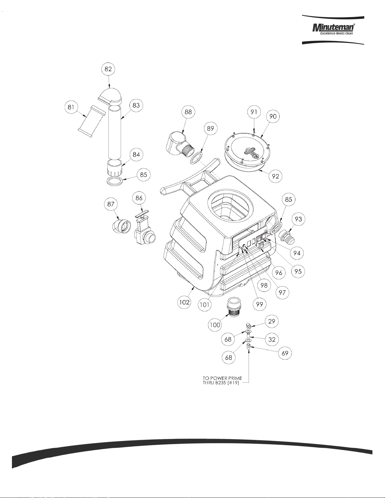
Page 12

EX12 - Recovery Tank Assembly
Parts an d Instructio n Ma nual
Page 9
Page 13

EX12 - Bill Of Materials
Bill Of Material - EX12
Item Part No. Qty. Description Item Part No. Qty. Description
1 121052 2 cap, ax l e, 1/ 2" 40 121155 2 bolt , 1/ 4-20 x 1-1/ 4" hex head
2 121059 2 wheel, 1 2" 41 121119 2 Bracket, L 070-0 36
3 121167 6 washer, ax l e, c ut 1/2" id 42 121209 1 sol t a nk, speedster
4 121066 1 axl e , 1/2" x 18 -1/2" , sp, breez e 43 121075 1 bracket , rear, fb/spy
5 121162 12 nut, lock, 1/4 -20, nylon in sert 44 121160 6 washer, 1/ 4" loc k, s/s
6 121157 16 washer, 1/ 4" flat, s /s 45 121076 2 knob , thum b screw, for bracket
7 121175 8 bolt , 1/ 4-20 x 1" hex he ad, s/s 46 121018 1 elbow, b rass, 90 deg, 3 /8" m pt x 3 /8" fmpt
8 121073 2 caste r, 5" 47 121173 2 washer, 11/ 16"id x 1-1/ 2"od x .075, s/s
9 1 2120 8 1 base, speedster 48 121020 1 nippl e, bras s, 3/8" x c l ose
10 121061 2 guard, cooli ng fan, wire 49 121019 1 bushi ng, bras s, 1 /2" m pt x 3/8" fpt, hex
11 121203 8 screw, #10 x 5/8" hex hea d, zi n c 50 121012 1 filter, strai n er, 1/ 2"
12 121163 1 nut, lock, 1/2 " s t e el 51 121 068 1 brac ket, front hinge, sp/fb
13 121053 1 fitting, strain rel ief, cord 52 121202 2 bolt, 1/4-20 x 1-1/ 2" hex head , s/s
14 121032 1 power co rd, end, 2 5', 1 4/3 grey 5 3 121005 2 elbo w, b rass , 90 deg, 1 /4"m pt x 1 /4" fpt
15 121181 2 bolt , 1/ 4-20 x 3/ 4" s errated hex flange, zinc 54 121159 4 was her, 9/16"i d x 1" od, flat, s/s
16 121117 1 plat e , si ng l e manifol d, 6.5" x 9 " 55 121 008 1 nipple, bra ss, 1/4 " m, hex
17 121211 1 manifold, single vac 56 121149 1 hose , 3/8" x 17 -1/2" , (OAL), f x -fs w, surge , 1600ps i
18 121154 5 bolt , 1/ 4-20 x 1/ 2" hex h ead, z i nc 57 121177 2 washer, ny l on , 9/16id x 1-1/16od x . 031
19 121038 1 gasket , vacuum motor 58 121007 1 nippl e, bras s, 1/4" x c l ose
20 121125 3 va c sup port, 3 sta ge, 4-1/ 16" 59 121010 1 adapt er, bras s, exte nder, 1/4 " mpt x 1/4" fpt, hex
21 121182 9 bolt , 1/ 4-20 x 1/ 2" s errated hex flange, zinc 60 121004 1 qd, bra ss, 1/ 4 " f
22 121021 1 va c mot or, 3 stage , 115V, tan gential 61 121069 1 float , 2", ball styl e
23 121042 1 exha ust bo ot, pl astis ol 62 121077 1 elbow, 2 " fl oat
24 121126 1 cuff, 2" 63 121135 1 pipe, pvc, 2"
25 121192 1 va c hos e, 2" , wire rein forc e d 64 121137 1 adapt or, pvc 2, fms l x fmt
26 121051 2 cl amp, hose, 2-1/4 DIA 65 121200 2 gask et, 2" inlet polyethylene, 3 " O D 2.35" ID
27 121196 1 sol hose, 1 /4" x 24 1/2 " , (OA L), f x fsw, 3000p si 66 121055 1 spou t, drai n , 45 degree
28 121014 1 elbow, b rass, 90 deg, 1 /4" m pt x 1 / 4 " mpt 67 121054 1 valve, drain, 1-1/2 "
29 121006 1 bush i ng, bras s, 3/8" mpt x 1/4 " 68 121210 1 vac tank , spee dster
30 121016 1 adapt er, bras s, 1/2" barb x 3/8" fsw, ba l l end 69 121138 2 inl et, 2"
31 121017 1 elbow, b rass, 90 deg, 1 /2" barb x 3/ 8"mpt 70 121072 2 washer, #8 flat, s/s
32 121064 2 cl amp, hose, 5/16-29/ 32 71 121176 2 screw, #1 0-32 x 1/ 2" SHCS , all o y
33 121190 1 sol h ose, 1 /2" kuri 100psi 72 121063 1 plat e , swi tch, sp, 3 hole
34 121169 4 nut, ke p, #10-32 z i n c 73 121028 2 swi tch, roc ker, 2 position
35 121164 4 screw, #1 0-32 x 1-1/ 4" phi l pan head, z i nc 74 121217 1 gas ket, vac lid, 6.5" i.d 7 .5" o.d
36 121022 1 pump, 100ps i , demand, 115V 75 121 044 1 lid, vac tank, black , 7"
37 121161 2 nut, hex , 1/4-2 0 s/s 76 121174 6 sc rew, #8 x 5/8 phil oval, s/ s
38 121158 4 washer, 1/ 4"id x 1"od, flat, s /s 77 121114 1 gasket , 2" i nlet
39 121041 4 washer, buna 1-1/8" od x 3/ 16" id 78 12119 4 1 el bo w, inlet as sembl y 2"
Parts an d Instructio n Ma nual
Page 10
Page 14

EX12H - Base Assembly
Parts an d Instructio n Ma nual
Page 11
Page 15

EX12H - Solution T ank Assembly
Parts an d Instructio n Ma nual
Page 12
Page 16
EX12H - Recovery Tank Assembly
Parts an d Instructio n Ma nual
Page 13
Page 17

EX12H - Bill Of Materials
BILL OF M ATERIAL - EX12H
ITEM PART NO. QTY. DES CRIP T ION I T EM P ART NO . Q T Y. DESCRIPT ION
1 121163 2 NUT-LOCK 1/2" STEEL 52 121125 3 SUP P ORT-VAC 3 STAGE 4-1/16"
2 121053 2 FITTING-STRAIN RELIEF CORD 53 121182 9 BOLT-SERRATED 1/4-20 X 1/2"
3 121032 2 CORD-POWER END 25' GRY 54 121021 1 MOTOR-VAC 3 STAGE 115V TANG
4 121052 2 CAP-AXLE 1/2" 55 121042 1 EXHAUST BOOT-PLASTISOL
5 121059 2 WHEEL-12" 56 121126 1 CUFF-HOSE 2 X 2 WIRE REINFORCED
6 121167 6 W A S HER-AXLE CUT 1/2" ID 57 121192 1 HOSE-V A C 2" W IRE REINFORCED
7 121066 1 AXLE-SP 1/2" x 18-1/2" 58 121051 2 CLAMP-HOSE 2-1/4 DIA
8 121208 1 BASE-SPEEDSTER BURGUNDY 59 121209 1 TANK-S O LU TION S PEEDSTER BURGUNDY
9 121162 12 NUT-LOCK 1/4-20 NYL INSERT 60 121161 2 NUT-HEX 1/4-20 S/S
10 121157 16 W A S HER-FLAT 1/4" S /S 61 121160 6 WASHER-LOCK 1/4" S / S
11 121175 8 BOLT-HEX HEAD 1/4-20 X 1" S /S 62 121158 4 WA SHER-FLAT 1/4" ID X 1" OD S/ S
12 121073 2 CASTER-5" 63 121041 4 W A S HER-BUNA 1-1/8" O.D. x 3/ 16"
13 121023 1 FAN-COOLING 115V 64 121155 2 BOLT-HEX HEA D 1/4-20 X 1-1/ 4"
14 121061 3 GUARD-COOLING FAN WIRE 65 121119 2 BRACKET-"L"
15 121203 8 SCREW-HEX HEAD #10 X 5/8" ZINC 66 121075 1 BRACKET-REAR FB/SP
16 121152 1 REGULATOR-200 PSI 67 121076 2 KNOB-THUMB SCREW FOR BRACKE T
17 121064 8 CLAMP-HOSE 5/16-29/ 32 68 121159 8 W A S HER-FLAT 9/16" ID X 1" OD
18 121226 1 sol hose, kuriyama, 3/8" 69 121010 3 ADAPTER-BRASS EXTENDER 1/4"
19 121227 2 adapter, brass , 3/8" barb x 1/ 4" fsw 70 121018 1 ELB OW-BRASS 90 DEG 3/8" MPT
20 121169 6 NUT-#10-32 ZINC 71 121173 2 WASHER-11/16" ID X 1-1/2"OD X .075 S/S
21 121168 2 SCREW-PHIL PH #10-32 X 3/4" 72 121020 1 NIPPLE-BRASS 3/8" x CLOSE
22 121228 1 bracket, heater mounting, dual 73 121019 1 BUSHING-BRASS 1/2" MPT x 3/8"
23 121074 2 HEATER-ALUMINUM CAST SINGLE 74 121012 1 FILTER-STRAINER 1/2"
24 121095 1 HEATING ROD-600 WATT 115V 75 121068 1 BRA CKE T-FRONT HINGE SP/F B
25 121030 1 HEATING ROD-1000W 115V 76 121202 2 B OLT-HEX HEAD 1/4-20 X 1-1/2" S/S
26 121035 2 THERMOSTAT- 200 DEG AUTO 1/4" V 77 121008 1 NIPPLE-BRASS 1/4" M HEX
27 121229 8 screw, #6 x 3/16, phil pan head, s el f-tapping 78 121149 1 HOSE-3/8" X 17-1/2" (OAL)
28 121036 2 THERMOSTAT-310 DEG F +/- 10 DEG F MAN 79 121177 2 WASHER-9/16 ID X 1-1/16 X .031 NYLON
29 121005 8 ELBOW-BRASS 90 DEG 1/4" MPT 80 121004 1 QD-BRASS 1/4" F
30 121151 1 HOSE- 3/8" X 6", (OAL) 81 121069 1 FLOAT-BALL STYLE 2"
31 121011 1 TEE-BRASS 1/4" FPT 82 121077 1 ELBOW-2" FLOAT
32 121007 4 NIPPLE-BRASS 1/4" x CLOSE 83 121135 1 PIPE-2" PVC
33 121149 1 HOSE-3/8" X 17-1/2" (OAL) 84 121137 1 ADAPTOR-2" FMSL x FMT PVC
34 121230 1 hose, 3/ 8" x 9" (OAL), f x f, s urge, 1600psi 85 121200 2 GASK E T-2" INLET POLYETHYLENE 3" OD 2. 35" ID
35 121164 4 SCREW-PHIL PH #10-32 X 1-1/4" ZINC 86 121054 1 VALVE-DRAIN 1-1/2"
36 121024 1 PUMP-250 PSI BYPASS 115V 87 121055 1 SPOUT-DRAIN 45 DEG
37 121231 1 plug, brass, 1/4"mpt, hex 88 121002 1 ELBOW-INLET ASSY 1-1/2"
38 121131 1 VALVE-PRIME HIGH PRESSURE 89 121114 1 GASKET, 2" INLET
39 121232 1 adapter, brass, 3/8" barb x 1/4"mpt 90 121044 1 LID-VAC TANK 7" BLACK
40 121233 1 sol hose, kuriyama, 3/8" 91 121174 6 SCREW-PHIL OVAL #8 X 5/8 S/S
41 121014 1 ELBOW-BRASS 90 DEG 1/4" MPT 92 121217 1 GASKET-VAC LID 6.5" ID 7.5" OD
42 121234 1 adapter, brass , 1/2" barb x 1/ 4" mpt 93 121056 1 FITTING-INLET PVC 1-1/2"
43 121212 1 HOSE-SOLUTION 1/2" KURI 100 PSI 21" 94 121025 2 LIGHT-RED 250V
44 121104 1 FILTER CUP IN-LINE 95 121029 1 SW ITCH-ROCKER 3 POSITION
45 121235 1 sol hose, 1/2" kuri 100psi 96 121028 2 SWITCH-ROCKER 2 POSITION
46 121016 1 REDUCER-BRASS SWIVEL BALL 97 121026 1 LIGHT-INDICATOR 125V AMBER
47 121181 2 BOLT-SERRATED 1/4-20 X 3/4" 98 121176 2 SCREW-SHCS #10-32 X 1/2" ALLOY
48 121117 1 PLATE-SINGLE MANIFOLD 6.5" 99 121072 2 WAS HER-FLAT #8 S/S
49 121154 5 BOLT-HEX HEAD 1/4-20 X 1/2" 100 121138 1 INLET-2"
50 121211 1 MANIFOLD-SINGLE VAC 101 121065 1 P LA TE-S WITCH SP 4 HOLE
51 1 2 10 3 8 1 G ASKET-VAC M O TOR 102 1 2 12 1 0 1 TA NK-V AC SPEEDSTE R BURGUNDY
Parts an d Instructio n Ma nual
Page 14
Page 18

Minuteman International Made Simple Commercial Limited Warranty
REVISION F
EFFECTIVE 6/1/2009
Minuteman International Made Simple Commercial Limited Warranty
Minuteman International, Inc. warrants to the original purchaser/user that the product is free from defects in workmanship and materials under
normal use. Minuteman will, at its option, repair or replace without charge, parts that fail under normal use and service when operated and
maintained in accordance with the applicable operation and instruction manuals. All warranty claims must be submitted through and approved
by factory authorized repair stations.
This warranty does not apply to normal wear, or to items whose life is dependent on their use and care, such as belts, cords, switches, hoses,
rubber parts, electrical motor components or adjustments. Parts manufactured by Minuteman are covered by and subject to the warranties
and/or guarantees of their manufacturers. Please contact Minuteman for procedures in warranty claims against these manufacturers.
Special warning to purchaser — Use of replacement filters and/or prefilters not manufactured by Minuteman or its designated licensees, will
void all warranties expressed or implied. A potential health hazard exists without original equipment replacement.
All warranted items become the sole property of Minuteman or its original manufacturer, whichever the case may be.
Minuteman disclaims any implied warranty, including the warranty of merchantability and the warranty of fitness for a particular purpose.
Minuteman assumes no responsibility for any special, incidental or consequential damages.
This limited warranty is applicable only in the U.S.A. and Canada, and is extended only to the original user/purchaser of this product.
Customers outside the U.S.A. and Canada should contact their local distributor for export warranty policies. Minuteman is not responsible for
costs or repairs performed by persons other than those specifically authorized by Minuteman. This warranty does not apply to damage from
transportation, alterations by unauthorized persons, misuse or abuse of the equipment, use of non-compatible chemicals, or damage to
property, or loss of income due to malfunctions of the product.
If a difficulty develops with this machine, you should contact the dealer from whom it was purchased.
This warranty gives you specific legal rights, and you may have other rights which vary from state to state. Some states do not allow the
exclusion or limitation of special, incidental or consequential damages, or limitations on how long an implied warranty lasts, so the above
exclusions and limitations may not apply to you.
Cord Electric Group: Three years parts, two years labor, ninety days travel (Not to exceed two hours)
Exceptions……….
Model Parts Labor Poly Travel
Port A Scrub 1yr 6months 10yrs 0
MPV 13 1yr 0 0 0
MPV 14 & 18 2yrs 1yr 0 0
V Series Upright Vacuums 1yr 1yr 0 0
Rapid Air Blower 1yr 1yr 10yrs 0
Explosion Proof Vacuum 1yr 1yr 0 0
X12, X12H & TRS 14 1yr 1yr 10yrs 0
E17 & E20 Electric Scrubbers 1yr 6month 10yrs 0
Pneumatic Vacuums 3yr 1yr 0 0
Description Parts Labor Poly Travel
Battery Operated Group 3yrs 2yrs 10 90 days
Sweepers 1yr 1yr 10 90 days
Internal Combustion Group 1yr 1yr 10 90 days
Not to exceed two hours
Exception: PAS 14B 1yr 1yr 10yr 0
Battery Chargers: One year replacement
Replacement Parts: Ninety days
Batteries: 0-3 months replacement, 4-12 months pro-rate
Polyethylene Plastic Tanks: Tanks have 10yr warranty, no additional labor
14N845 U.S. Route 20, Pingree Grove, IL 60140 USA
Phone (800) 323-9420 - www.minutemanintl.com
A Member of the Hako Group
985012
REV C 08/10
 Loading...