

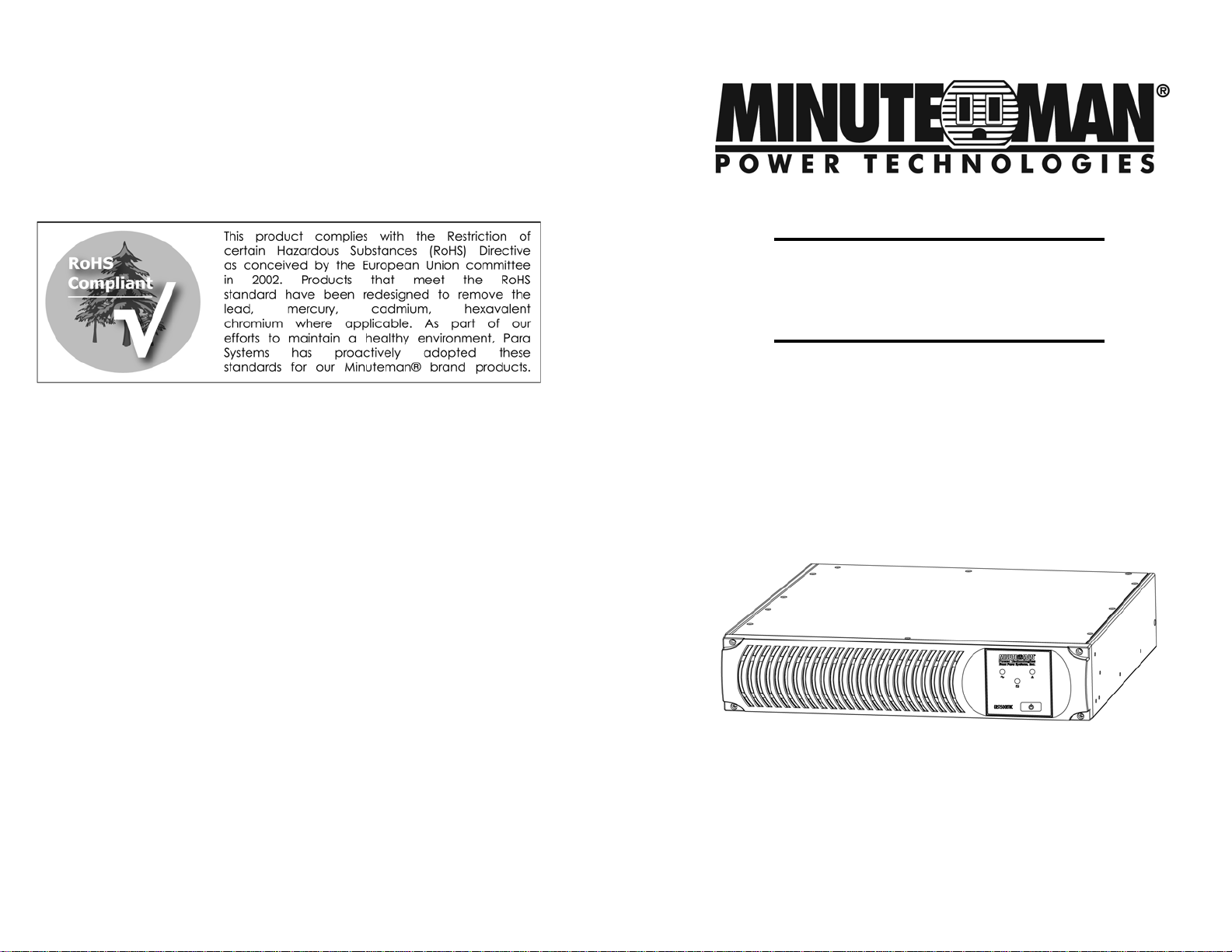
Minuteman ERS1500RTNC User Manual
Para Systems, Inc.
1455 LeMay Dr.
Carrollton, TX 75007
Phone: 1-972-446-7363
Fax: 1-972-446-9011
Internet: minutemanups.com
UPS Sizing: sizemyups.com
ERS1500RTNC
Series UPS
User's Manual
PN - 34000438 R2

1. Introduction 2
2. Controls and Indicators 6
3. Installation 7
4. Operation 13
5. Troubleshooting 16
6. Replacing the Battery 17
7. Obtaining Service 21
8. Specifications 22
9. Limited Product Warranty 24
A1 . Declaration of Conformity 25
1

Thank you for purchasing this power protection product. It has been designed
and manufactured to provide many years of trouble free service.
NOTICE! The output of this device is not sinusoidal. It has a total harmonic
distortion and maximum single harmonic as below:
T otal harmonic 42.8% Single harmonic 26.6%
CAUTION! Connect the UPS to a two pole, three wire grounding AC wall
outlet. The receptacle must be connected to the appropriate branch protection (circuit breaker or fuse). Connection to any other type of receptacle may
result in a shock hazard and violate local electrical codes. Do not use extension cords, adapter plugs, or surge strips.
IMPORT ANT SAFETY INSTRUCTIONS
CONSIGNES DE SÉCURITÉ IMPORT ANTES
SA VE THESE INSTRUCTIONS !
SAUVEGARDEZ CES CONSIGNES!
Please read this manual before installing your UPS, model ERS1500RTNC as
it provides important information that should be followed during installation and
maintenance of the UPS and batteries allowing you to correctly set up your
system for the maximum safety and performance.
Veuillez lire ce manuel avant l'inst allation de l'onduleur modèle ERS1500RTNC.
Il contient de l'information importante qui doit être respectée au cours de
l'installation et de l'entretien de l'onduleur et des batteries. Cette information
vous permettra de correctement installer le système pour atteindre son
rendement maximum en toute sécurité.
Included is information on customer support and factory service if it is required. If you experience a problem with the UPS please refer to the Troubleshooting guide in this manual to correct the problem or collect enough information so that the Technical Support Department can rapidly assist you.
CAUTION! This UPS is intended to be installed in a temperature/humidity
controlled environment that is free of conductive contaminants.
ATTENTION! Cet onduleur est conçu pour installation dans un milieu à
température et humidité contrôlées, libre de contaminants conducteurs.
This UPS series is not intended for use in a computer room as defined in the
Standard for the Protection of Electronic Computer/Data Processing Equipment ANSI/NFPA 75.
CAUTION! To reduce the risk of fire, connect only to a circuit provided with
20 amperes maximum branch circuit over-current protection in accordance
with the National Electric Code, ANSI/NFPA 70.
CAUTION! T o reduce the risk of electrical shock with the installation of this
UPS equipment and the connected equipment, the user must ensure that the
combined sum of the AC leakage current does not exceed 3.5mA.
CAUTION! To reduce the risk of electrical shock in conditions where the
load equipment grounding cannot be verified, disconnect the UPS from the
AC wall outlet before installing a computer interface cable. Reconnect the
power cord only after all signaling connections are made.
WARNING: This Uninterruptible Power Supply cont ains potentially hazard-
ous voltages. Do not attempt to disassemble the UPS beyond the battery
replacement procedure. This UPS contains no user serviceable parts. Repairs and Battery replacement must be performed by QUALIFIED SERVICE
PERSONNEL ONL Y.
WARNING: Risk of Electrical Shock. Hazardous live parts inside these
power supplies are energized from the battery even when the AC input is
disconnected.
CAUTION! T o de-energize the output s of the UPS:
1. If the UPS is on press and release the On/Off/Test Button.
2. Disconnect the UPS from the AC wall outlet.
3. T o de-energize the UPS completely, disconnect the battery.
CAUTION! The Maximum ambient operating temperature for this UPS se-
ries is 50°C (“-15 ~ +50°C” for Ambient Operation).
2
CAUTION! DO NOT USE THE MOUNTING BRACKETS TO LIFT THE
UPS. The mounting brackets are ONLY for securing the UPS to the rack.
3
ON / OFF / TEST BUTTON: T o turn the UPS on: press and hold the On/Of f/
T est Button until the alarm sounds one beep and then release. The UPS will
perform a five second self-test. Once the UPS has passed its self-test the
UPS will provide an output and the load will be powered. To turn the UPS
off: press and hold the On/Off/Test Button until the alarm sounds one beep
and then release. T o perform a ten-second battery test: With the UPS in the
AC mode, press and hold the On/Off/T est Button until the alarm sounds four
beeps, and then release. During the test, the UPS will switch to the Battery
mode, the On-Battery icon will illuminate and the alarm will sound.
NOTICE: This equipment has been tested and found to comply with the limits for
a Class B computing device in accordance with the specifications in Subpart J of
Part 15 of FCC Rules and the Class B limits for radio noise emissions from digital
apparatus set out in the Radio Interference of the Canadian Department of Communications. These limits are designed to provide reasonable protection against
such interference in a residential installation. This equipment generates and uses
radio frequency and if not installed and used properly , that is, in strict accordance
with the manufacturer's instructions, this equipment may cause interference to radio and television reception. If this equipment does cause interference to radio or
television reception, which can be determined by turning the equipment off and on,
the user is encouraged to try to correct the interference by one or more of the following measures:
Reorient the receiving antenna.
Relocate the computer with respect to the receiver.
Move the computer away from the receiver.
Plug the computer into a different outlet so that the computer and receiver
are on different branch circuits.
Shielded communications interface cables must be used with this product.
WARNING: Changes or modifications to this unit not expressly approved by the
party responsible for compliance could void the user's authority to operate the equipment.
Receiving Inspection
After removing your UPS from its carton, it should be inspected for damage that
may have occurred in shipping. Immediately notify the carrier and place of purchase if any damage is found. Warranty claims for damage caused by the carrier
will not be honored. The packing materials that your UPS was shipped in are carefully designed to minimize any shipping damage. In the unlikely case that the UPS
needs to be returned to the manufacturer, please use the original packing material.
Since the manufacturer is not responsible for shipping damage incurred when the
system is returned, the original packing material is inexpensive insurance. PLEASE
SAVE THE PACKING MATERIALS!
NOTE: These UPSs are shipped with the batteries disconnected. The batteries
must be connected before putting these UPSs into service. Refer to Section 3
"Installation" for connecting the batteries.
4
Life Support Policy
As a general policy , we do not recommend the use of any of our products in life
support applications where failure or malfunction of the product can be reasonably expected to cause failure of the life support device or to significantly affect
its safety or effectiveness. We do not recommend the use of any of our products in direct patient care. We will not knowingly sell our products for use in
such applications unless it receives in writing assurances satisfactory to us
that (a) the risks of injury or damage have been minimized, (b) the customer
assumes all such risks, and (c) our liability is adequately protected under the
circumstances.
Examples of devices considered to be life support devices are neonatal oxygen
analyzers, nerve stimulators (whether used for anesthesia, pain relief, or other
purposes), auto transfusion devices, blood pumps, defibrillators, arrhythmia
detectors and alarms, pacemakers, hemodialysis systems, peritoneal dialysis
systems, neonatal ventilator incubators, ventilators for both adults and infants,
anesthesia ventilators, and infusion pumps as well as any other devices designated as “critical” by the United States FDA. These UPSs do not meet the
requirements for use in direct patient care.
© COPYRIGHT 2014 BY PARA SYSTEMS, INC.
All Rights Reserved. All right s of this User Manual (“Manual”), including but not
limited to the content, information, and figures are solely owned and reserved
by Para Systems, Inc. (“Para Systems”). The Manual can only be applied to
the operation or the use of this product. Any disposition, duplication, dissemination, reproduction, modification, translation, extraction, or usage of this
Manual in whole or in part is prohibited without the prior written permission of
Para Systems. Given that Para Systems will continuously improve and develop
the product, changes may be made to the information in this Manual at any
time without obligation to notify any person of such revision or changes. Para
Systems will make all possible efforts to secure the accuracy and the integrity
of this Manual. Para Systems disclaims any kinds or forms of warranty , guarantee, or undertaking, either expressly or implicitly , including but not limited to
the completeness, faultlessness, accuracy , non-infringement, merchantability
or fitness for a particular purpose of the Manual.
5
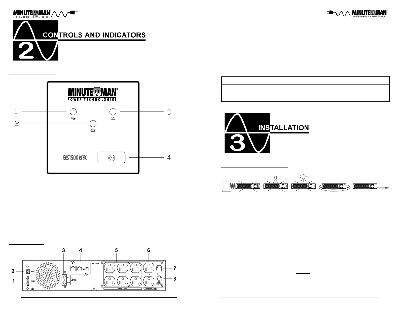
CONTROL PANEL
1. RS232 Communications Port is for UPS monitoring and control.
2. USB Communications Port is for UPS monitoring and control.
3. The RJ1 1/45 are used for phone/fax/modem and network protection.
4. SNMP Card is for UPS monitoring and control (Included).
5. Battery Backup & Surge output receptacles for mission critical equipment.
6. Surge ONL Y output receptacles for noncritical equipment.
7. Input power cord is for connecting to the Utility Power.
8. Input circuit breaker is for protection against an excessive overload.
1. AC normal and Boost/Buck mode LED (Green): Illuminates when the UPS
is in the AC normal mode and flashs when the UPS is in the Boost or the
Buck mode.
2. Battery mode LED (Y ellow): Illuminates when the UPS is operating in the
Battery mode.
3. Fault LED (Red): Illuminates when the UPS has detected an internal fault.
4. On/Off/Test Button: To turn the UPS On/Off and to perform a ten-second
battery test.
REAR P ANEL
Model # Input Power Plug
ERS1500RTNC
NEMA 5-15P
W/10 ft cord
Output Power Receptacles
6-NEMA 5-15R Battery Backup & Surge
2-NEMA 5-15R Surge Only
INST ALLATION PLACEMENT
This UPS is intended to be installed in a temperature/humidity controlled environment that is free of conductive contaminants. DO NOT operate the UPS in:
extremely dusty and/or unclean areas, locations near heating devices, water
or excessive humidity , or where the UPS is exposed to direct sunlight. Select
a location, which will provide good air circulation for the UPS at all times.
Route power cords so they cannot be walked on or damaged. Typical battery
life is 2 to 3 years. Environmental factors do affect battery life. High temperatures, poor utility power, and frequent, short duration discharges have a negative impact on battery life.
CAUTION! DO NOT USE THE MOUNTING BRACKETS TO LIFT THE
UPS. The mounting brackets are ONLY for securing the UPS to the rack.
6
7
 Loading...