

Page 1

User Manual
E Ride 28/32 Rider Scrubber
Page 2

Technical Specifications
This manual is furnished with each new MINUTEMAN ERide 28/32. This provides the necesary operating and preventive maintenance instructions. Operators must read and understand this manual before operating or servicing this machine.
This machine was designed to give you excellent performance and efficiency. For best results and minimal cost, please follow
the general guidelines below:
- Operate the machine with reasonable care.
- Follow the manufacturers suggested maintenance instructions as provided in this manual.
- Use original Minuteman supplied parts.
Model E Ride
Model No. ER28C, ER28CPLUS, ER28CQP, ER28D, ER28DPLUS, ER28DQP,
ER32C, ER32CPLUS, ER32CQP, ER32D, ER32DPLUS, ER32DQP
Current 60 Amps
Voltage, Batteries 36 volts, 6-6volt
Battery Capacity 235 Ah (Optional 395 Ah batteries available)
Sound Level 75 dB
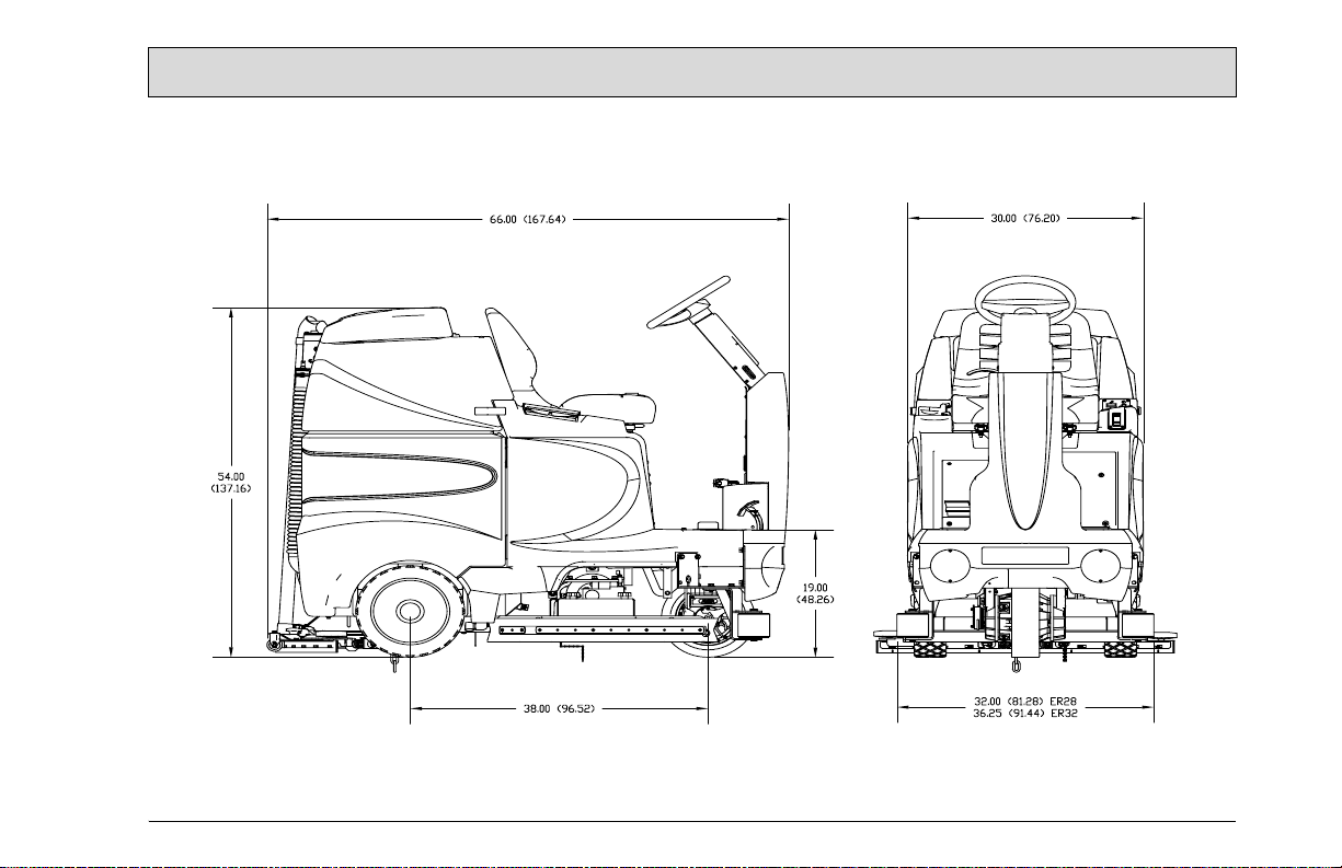
Dimensions (LxWxH) 66" x 31" x 54" (167.64cm x 78.74cm x 137cm)
Gross Weight 1,243 lbs (564 kg) with batteries
847 lbs (384 kg) without batteries
Working Grade Transport 10% (7°)
Wheel to Floor Pressure 64 PSI Front, 69 PSI Rear
2
TM
28/32
Page 3
3
Page 4

Introduction
Preface
Dear customer, Thank you for purchasing the Minuteman® E Ride. The outstanding operational characteristics of
the E Ride should justify the confidence
you demonstrated in making this purchase.
The E Ride is a commercial grade Rider
Scrubber machine. It is battery operated and is intended by Minuteman to be
used in accordance with this manual,
the labels on the machine itself, as well
as applicable federal, state, and local
safety and environmental statutes, regulations, and ordinances (collectively
the "governmental regulations"), applicable commercial standards, and common sense. .
The user's own safety, as well as the
safety of others, depends to a great extent on how the E Ride is operated, handled, and maintained. Therefore, as a
starting point, this manual must be read
and understood thoroughly prior to the
machine being switched on for the first
time. When operating or maintaining
the E Ride, THINK SAFETY FIRST!
This manual provides vital information
concerning the safe operation, use,
maintenance, and service of the E Ride.
The various safety alert symbols, signal
words, and safety messages contained
herein are intended to be read in conjunction with each other, as well as with
E Ride labels, instruction plates, and
applicable governmental regulations.
To the extent that any governmental
regulations conflict with the provisions
of this instruction manual, such governmental regulations would govern.
Your authorized Minuteman dealer
would be happy to answer any questions you may have concerning the operation or maintenance of the E Ride or
information contained in this manual.
If repair or maintenance work is performed on the E Ride, Minuteman recommends that only genuine
replacement parts be used and that
such work be performed by qualified individuals.
Proper use
The E Ride is a floor scrubing machine.
Its intended scope of application is for
wet cleaning of level, hard-surfaced
floors in accordance with the provisions
of this instruction manual, applicable
governmental regulations, manufacturer specifications, and machine labels
(collectively, "proper use"). Using the E
Ride beyond its proper use will be
deemed improper use by Minuteman.
Minuteman disclaims any liability for
any personal injury, property, or other
damages of any nature whatsoever,
whether special, indirect, consequential, or compensatory, directly or indirectly resulting from the improper use of
the E Ride, or uses beyond or inconsistent with the E Ride’s intended scope of
application. This disclaimer of liability
also extends to modifications to the E
Ride made without Minuteman's prior
written consent.
The E Ride should only be operated,
handled, and maintained by persons
who are familiar with the machine and
who have been instructed of the potential hazards associated with such operation, handling, and maintenance.
4
Page 5

Introduction
Disclaimer:
Minuteman disclaims liability for any
personal injury, property, or other damages of any nature whatsoever, whether special, indirect, consequential, or
compensatory, directly or indirectly resulting from the publication, use of, application, or reliance on this document
or, except as expressly set forth in the
sales contract for the machine, the operation or maintenance of the E Ride.
EXCEPT AS EXPRESSLY SET
FORTH IN SUCH SALES CONTRACT,
MINUTEMAN MAKES NO WARRANTIES, EXPRESS OR IMPLIED, AND
SPECIFICALLY DISCLAIMS ANY
WARRANTY OF MERCHANTABILITY
OR FITNESS FOR A PARTICULAR
PURPOSE.
Minuteman disclaims and makes no
guaranty or warranty, express or implied, as to the accuracy or completeness of any information published
herein, and disclaims and makes no
warranty that the information in this instruction manual will fulfill any parties'
particular purposes or needs. While
Minuteman believes that the information in this manual is accurate, in the
event that technical or typographical er-
rors exist in this manual, Minuteman reserves the right to make changes to
subsequent editions of this manual
without prior notice to the recipients of
this edition. The reader should notify
Minuteman if any errors in this manual
are suspected. Minuteman does not undertake to guarantee the performance
of any individual manufacturer or seller's products or services by virtue of this
instruction manual.
In publishing and making this manual
available, Minuteman is not undertaking
to render professional or other services
for or on behalf of any person or entity,
nor is Minuteman undertaking to perform any duty owed by any person or
entity to someone else. Anyone using
this manual should rely on his or her
own independent judgment or, as appropriate, seek the advise of a competent professional in determining the
exercise of reasonable care in any given circumstances.
Valid as of: August 2010
Minuteman International Inc.
14N845 U.S. ROUTE 20
PINGREE GROVE, IL. 60140
U.S.A.
5
Page 6

Notes on warranty
The terms of the sales contract apply in
regard to any product warranties. Minuteman expressly disclaims all other
warranties, either express or implied, of
any kind. It should be noted, however,
that failure to maintain and service your
E Ride in accordance with its proper
use may void the warranty. In this regard, any maintenance work must be
performed by an authorized Minuteman
service representative and confirmed in
the "Maintenance Certificate" - the warranty document. By way of example,
the following items are excluded from
the E Ride warranty: fuses; normal
wear and tear; improper machine handling; damages caused by overloads;
unauthorized machine modifications;
non-compliance with maintenance instructions or specifications; or improperly fitting parts or accessories.
Acceptance of the machine
Upon arrival, check machine for possible damages in transit. Follow unpacking instructions on shipping pallet. Each
unit has been tested and throughly inspected before shipment. Any damage
is the responsibility of the delivery carrier who should be notified immediately.
Minuteman International Inc.
14N845 U.S. ROUTE 20
PINGREE GROVE, II. 60140
U.S.A.
6
Page 7

The E Ride 28/32
This machine was designed with total operator comfort and ease of use in mind. All machine components have been designed as a total system
to efficiently clean dirty floors. The E Ride has four available scrub head types and sizes to fit specific applications. Please contact your Min-
uteman representative for specific recommendations for the correct scrub head type, size, and brush type and chemical applications.
Before using the machine, always perform the following steps to ensure proper machine operation.
•Check under the machine for leaks.
•Check the rear and side squeegees for wear and damage.
•Check the steering for proper operation.
•Check the solution and recovery tanks.
After using the machine, always perform the following steps:
•Check the battery charge level. Charge batteries if necessary. When charging batteries, extra pr ecaution is required:
Battery acid can cause burns.
When working on or around batteries, always wear protective clothing and safety glasses.
Remove metal jewelry. Do not lay tools or metal objects on top of the batteries.
Charging batteries generate explosive gasses.
DO NOT CHARGE BATTERIES WHEN OPEN FLAMES OR SPARKS ARE PRESENT. DO NOT SMOKE.
Make sure the charger is turned off before disconnecting it from the batteries.
Charge the batteries in a well-ventilated area.
Fluid levels should be checked before and after charging and maintained at the proper levels. If low, add water until the metal plates are cov-
ered.
If the machine is not used for an extended period of time, batteries should be kept fully charged with a boost charge once a week.
•Check for wire, string, or twine wrapped around the scrub brushes.
•Check the squeegees for wear and damage.
•Check the rear squeegee suction hose and off-aisle wand hose for obstructions.
•Empty and clean the debris box (cylindrical systems only).
•Drain and clean the recovery tank.
•Check under the machine for leaks.
•Check the service records to determine maintenance requirements.
WARNING!
•Be sure you understand the machine controls and their functions.
•While on ramps or inclines, avoid sudden stops when tanks are filled.
•Avoid abrupt sharp turns. Slow down driving speed when going downhill.
•Always drive up when cleaning ramps.
7
Page 8

8
Page 9

Table of Contents
Technical Specifications . . . . . . . . . . . . . . . . .2
Introduction. . . . . . . . . . . . . . . . . . . . . . . . . . . . 4
Notes on Warranty. . . . . . . . . . . . . . . . . . . . . . 6
Acceptance of the machine . . . . . . . . . . . . . . . 6
The E Ride 28/32. . . . . . . . . . . . . . . . . . . . . . . .7
Important Safety Instructions . . . . . . . . . . . . . .10
Unpacking Instructions. . . . . . . . . . . . . . . . . . .11
1 Machine Overview . . . . . . . . . . . . . . . . . . . . .12
1.1 Machine Overview - Front . . . . . . . . . . . . . . . .12
1.2 Machine Overview - Rear. . . . . . . . . . . . . . . . .13
1.3 Operator Compartment . . . . . . . . . . . . . . . . . .14
1.4 Control Console . . . . . . . . . . . . . . . . . . . . . . . .16
1.5 Operation Modes . . . . . . . . . . . . . . . . . . . . . . .18
1.6 Fault/Diagnostic Codes . . . . . . . . . . . . . . . . . .20
1.7 Steering Wheel. . . . . . . . . . . . . . . . . . . . . . . . .21
1.8 Accelerator Pedal. . . . . . . . . . . . . . . . . . . . . . .21
1.9 Seat . . . . . . . . . . . . . . . . . . . . . . . . . . . . . . . . .21
1.10 Directional Switch. . . . . . . . . . . . . . . . . . . . . . .21
1.11 Parking Brake. . . . . . . . . . . . . . . . . . . . . . . . . .21
1.12 Circuit Breakers . . . . . . . . . . . . . . . . . . . . . . . .22
1.13 Battery Compartment. . . . . . . . . . . . . . . . . . . .22
Battery Connection Diagram . . . . . . . . . . . . . .23
1.14 Scrub Decks. . . . . . . . . . . . . . . . . . . . . . . . . . .24
1.15 Scrub Deck Installation. . . . . . . . . . . . . . . . . . .26
1.16 Side Squeegees. . . . . . . . . . . . . . . . . . . . . . . .28
1.17 Rear Squeegee . . . . . . . . . . . . . . . . . . . . . . . .30
2 First Operation . . . . . . . . . . . . . . . . . . . . . . . .32
2.1 Instruction. . . . . . . . . . . . . . . . . . . . . . . . . . . . .32
2.2 Initial charging procedure. . . . . . . . . . . . . . . . .32
2.3 Before Putting into Operation. . . . . . . . . . . . . .32
2.4 Start Machine. . . . . . . . . . . . . . . . . . . . . . . . . .32
2.5 Operation . . . . . . . . . . . . . . . . . . . . . . . . . . . . .33
2.6 Stop Machine. . . . . . . . . . . . . . . . . . . . . . . . . .34
2.7 After Work . . . . . . . . . . . . . . . . . . . . . . . . . . . .34
2.8 Transporting the machine . . . . . . . . . . . . . . . .35
2.9 Tie-down points . . . . . . . . . . . . . . . . . . . . . . . .35
3 Maintenance and Care. . . . . . . . . . . . . . . . . .36
3.1 Minuteman System
Maintenance. . . . . . . . . . . . . . . . . . . . . . . . . . .36
3.2 Maintenance Document. . . . . . . . . . . . . . . . . .37
3.3 Maintenance Schedule. . . . . . . . . . . . . . . . . . .38
4 Troubleshooting. . . . . . . . . . . . . . . . . . . . . . .44
5 Warranty . . . . . . . . . . . . . . . . . . . . . . . . . . . . .50
9
Page 10

IMPORTANT SAFETY INSTRUCTIONS
work area and especially if small children are present.
Operators must read and understand this manual before operating or maintaining this machine.
Do not operate this machine in flammable or explosive areas.
This machine is designed solely for scrubbing dirt and dust in an
indoor environment. Minuteman does not recommend using this
machine in any other capacity.
The following information below may cause a potential hazard to the
operator and equipment. Read this manual carefully and be aware
when these conditions can exist. Take necessary steps to locate all
safety devices on the machine and train the personnel operating the
machine. Report any machine damage or faulty operation immediately. Do not use machine if it is not in proper operating condi-
tion.
FOR SAFETY DURING OPERATION
Keep hands and feet clear of moving parts while machine is in operation.
Make sure all safety devices are in place and operate properly. All
covers, doors and latches must be closed and fastened before use.
During operation, attention should be paid to other persons in the
10
Electric motors and components can cause an explosion when operated near explosive materials or vapor. Do not operate this machine
near flammable materials such as solvents, thinners, fuels, grain
dust, etc.
Store or park this machine on a level surface only, with the key
switch in the off position. To prevent unauthorized use, machine
should be stored or parked with the key removed.
This machine is designed for level operation only. Do not operate
on ramps or inclines.
This machine is not suitable for picking up hazardous dusts.
Use caution when moving this machine into areas that are below
freezing temperatures. Any water in the tanks or hoses can cause
damage to the machine.
FOR SAFETY WHEN SERVICING OR MAINTAINING MACHINE
Stop on level surface and turn off machine.
Disconnect the power to the machine by pressing the Red Emergency Disconnect Button when charging batteries or during installation or removal of brushes.
Page 11

Avoid moving parts. Do not wear loose jackets, shirts, or sleeves
when working on machine.
This machine is battery operated and designed to operate on 36
Volts DC (6) 6-volt batteries.
Avoid contact with battery acid. Battery acid can cause burns. When
working on or around batteries, wear protective clothing and safety
glasses. Remove metal jewelry.
Do not lay tools or metal objects on top of batteries.
Charging batteries generates explosive gasses. Do not charge bat-
teries when open flames or sparks are present. Do not smoke.
Make sure the charger is turned off before disconnecting it from the
machine. Charge the batteries in a well-ventilated area with the battery cover removed completely.
Do not clean machine with a pressure washer.
Authorized personnel must perform repairs and maintenance. Use
Minuteman supplied replacement parts.
UNPACKING INSTRUCTIONS
Carefully unpack and inspect your E Ride Scrubber for shipping
damage. Follow unpacking instructions on shipping pallet. Each unit
has been tested and thoroughly inspected before shipment. Any
damage is the responsibility of the delivery carrier who should be
notified immediately.
The recommended batteries are rated 235Ah (Minuteman P.N.
956740).
We do not recommend mixing Amp Hour capacities. Any alternate
battery sets can be used if they are of equal physical size and
capacity.
Read this manual carefully before operating this machine.
The operator is responsible for taking care of the daily maintenance
and check ups of the machine to keep it in good working condition.
The operator must inform the service mechanic or supervisor when
scheduled maintenance is required as stated in the MAINTENANCE
section of this manual.
Before starting, familiarize yourself with the machine and its controls
(see “Machine Overview, Front”, “Machine Overview, Rear”, “Operator Compartment”, & “Control Console” diagrams).
SAVE THESE INSTRUCTIONS
11
Page 12

Machine Overview
1 Machine Overview
1.1 Machine Overview - Front
1 Front Drive Wheel
2 Side Squeegee
3 Accelerator Pedal
4 Steering T ilt Lever
5 Steering Wheel
6 Operator’s Seat
7 Recovery Tank Lid
8 Recovery Tank
9 Control Console
10Directional Switch
11Recovery Tank Safety Latch
12Battery Compartment
13Solution Tank
14Electrical Panel
15Rear Squeegee
16Rear Wheel
17Scrubdeck
18Roller Bumper
12
Fig.1
5
4
3
7
9
8
6
14
16
17
1
18
2
11
12
10
13
15
Page 13
Machine Overview
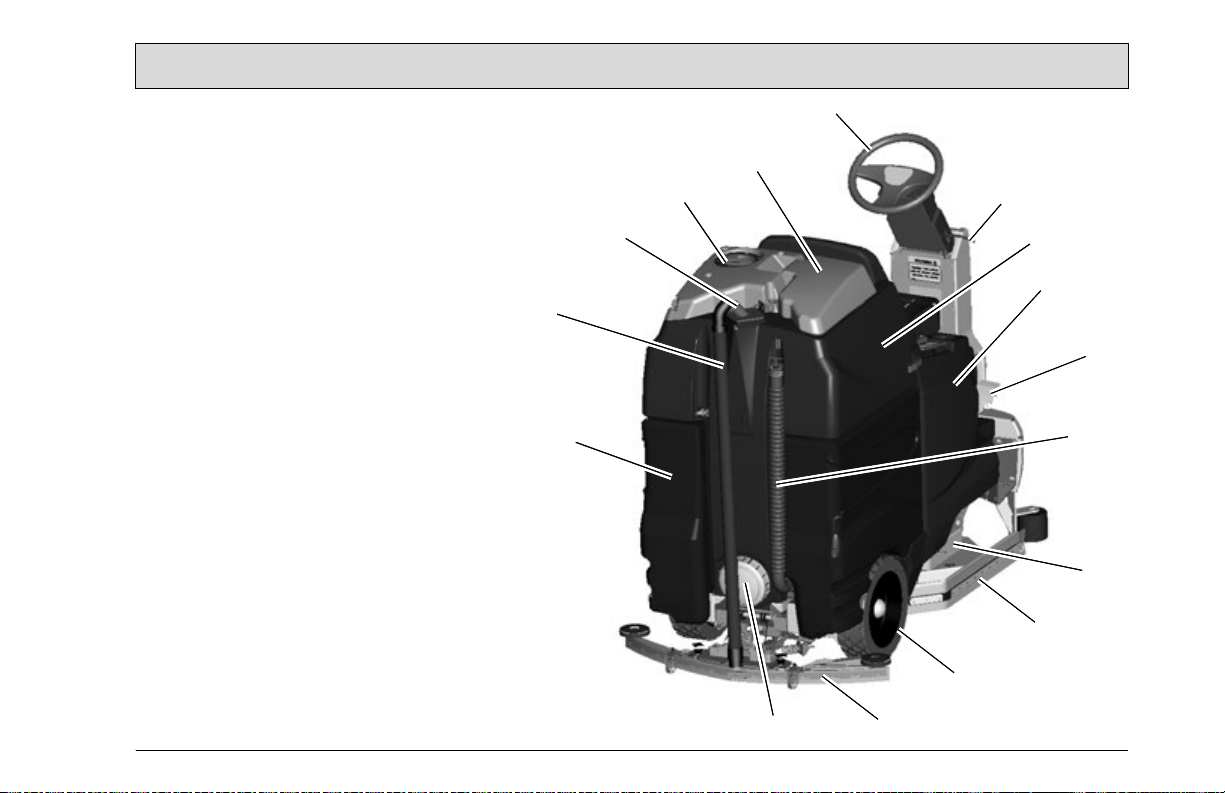
1.2 Machine Overview - Rear
19Rear Squeegee
20Rear Wheel
21Side Squeegee
22Accelerator Pedal
23Solution Tank
24Steering Tilt Lever
25Steering Wheel
26Recovery Tank Lid
27Vacuum Filter Access
28Vacuum Inlet Assembly
29Recovery Tank
30Battery Compartment
31Clean-Out Cap
32Recovery Drain Hose
33Recovery Vacuum Hose
34Scrubdeck
Fig.2
33
30
28
27
26
31
25
19
24
29
23
22
32
34
21
20
13
Page 14

Machine Overview
1.3 Operator Compartment
A Operator’s Seat
B Solution Tank Lid
C Cup Holder
D Solution tank
E Accelerator Pedal
F Steering Wheel
G Directional Switch
H Control Panel
I Recovery Tank Safety Latch
14
Page 15

Machine Overview
15
Page 16

Machine Overview
1.4 Control Console
For operator ergonomics, the control
console houses all the primary function
controls in a central area. The key
switch and optional headlight and offaisle wand switches are clustered in
the back portion of the console. The
directional switch (forward/reverse) is
located at the front of the console for
easy fingertip operation. The horn button, function selectors, and battery
gauge are located in the central part of
the console.
Key Switch (A) - S2
Controls the machine’s power (ON/
OFF) with a key for safety. All operational settings are retained even when
the power is turned off and on. This
also serves as a reset switch when
errors or faults occur.
Off Aisle Wand Switch (OPTIONAL)
(B) - S7 (281900 OPTIONAL)
16
ON/OFF control for the water supply to
the wand and vacuum motor for the
optional Off-Aisle Wand.
Headlight Switch (OPTIONAL) (C) S10 (281990 OPTIONAL)
ON/OFF control for the optional headlights.
Battery Gauge (D) - BD1
Displays the level of charge remaining
in the machine’s batteries. The gauge
consists of 10 LEDs. (3 Green, 4
Amber, 3 Red) If the battery life is low,
the battery gauge bar icon will be flashing to inform the operator that the
machine is almost out of power. Once
Page 17

Machine Overview
this signal is displayed, all functions will shut off, including
transport mode. The operator must then turn the key switch
OFF and then ON to reset the machine. The machine will
then have only a few minutes left of reserve power to briefly
use Vacuum Only mode to pick up any remaining solution on
the floor and Transport mode to return to the charging station. This gauge will also display a fault code if the system
has an error. This code is represented by a specific number
of flashing LEDs. See Fault/Diagnostic Codes for specific
code information.
Solution Control Knob (E) - R2
Adjusts the amount of solution being dispensed to the floor
while in one of the scrub modes. Turn the knob clockwise to
increase the amount of solution being dispensed. The
amount of solution applied is variable to a maximum of 1
GPM.
Mode Selector Knob (F) - S4
This knob is used to select the desired operation mode of the
machine. See Operation Modes for information about each
mode.
Horn Button (G) - S3
Depressing this button will activate the machine’s horn.
Directional Switch (H) - S6
Pressing switch to the down position will set the machine to
move forward. Pressing it to the up position sets the machine
to move in reverse.
17
Page 18

Machine Overview
1.5 Operation Modes
1. Regular Scrub Mode
When the machine is running in this mode, the machine will perform
all operations. This mode can be used for day-to-day tasks under normal conditions. When the operator sets the directional switch to for-
ward and activates the accelerator pedal, the solution pump will turn
on, the brushes will turn on and be lowered to the floor, as well as the
rear squeegee. While operating in this mode, the solution will be dispersed into the brushes, which will scrub the floor allowing the chemical in the solution to break down the dirt on the floor. As the machine
continues to move forward, the rear squeegee and vacuum system
will recover the dirt and dispensed solution. If the operator stops moving, the machine will automatically raise the scrub deck and turn off
the brushes. If the directional switch is changed to reverse the machine will continue to operate normally, only the rear squeegee will
raise up.
2. Heavy Scrub Mode
This mode is similar to Regular Scrub. The machine will continue to
operate the same was as if it was in Regular Scrub Mode, only this
mode applies more solution and brush pressure is increased. This
mode is used for high traffic areas and areas that have been heavily
soiled, but do not require time for the solution to soak.
3. Double Scrub Mode
When the machine is running in this mode, the machine will perform
all operations except dirty solution recovery. This mode can be used
if the floor is heavily soiled and the chemical will need additional time
to emulsify grease and oils that are on the floor. When the operator
sets the directional switch to either the forward or reverse position
and activates the accelerator pedal, the solution pump will turn on,
the brushes will turn on and be lowered to the floor. While operating
in this mode, the solution will be dispersed into the brushes, which will
scrub the floor allowing the chemical in the solution to break down the
dirt on the floor. As the machine continues to move forward or back,
the rear squeegee and vacuum system are not on, which allows the
18
solution to stay on the floor emulsifying the grease and oil. If the operator stops moving in either direction, the machine will automatically
raise the scrub deck and turn off the brushes. After double scrubbing,
the operator should use the vacuum only mode to recover the dirty
solution water from the floor.
4. Vacuum Only Mode
When the machine is running in this mode, the machine will only lower the rear squeegee and turn on the vacuum system to recover the
dirty solution from the floor. This mode is usually chosen after double
scrubbing to recover the dirty solution but it can also be used to pick
up spills. When the operator sets the directional switch to forward, the
rear squeegee will be lowered to the floor as the vacuum turns on,
pulling the dirty solution water from the rear squeegee into the recovery tank. If the operator stops moving forward and sets the directional
switch to reverse, the rear squeegee will retract (protecting it from
damage) and the vacuum motor will turn off after a few seconds. If the
operator quits moving in either direction, the machine will automatically raise the squeegee and turn off the vacuum motor after a few
seconds.
5. Transport Mode
When the machine is set in this mode, none of the cleaning functions
of the machine will operate. This mode is only used to transport the
machine from one location to another.
6. Solution Control Knob
This control will adjust the amount of solution that is being dispersed
to the floor while in one of the scrub modes. Adjust the control clockwise to increase the amount of solution being dispersed. The amount
of solution applied is variable to a maximum of 1 GPM.
7. Battery Gauge
This gauge displays the level of charge remaining in the machine’s
batteries. The gauge consists of 10 LEDs. (3 Green, 4 Amber, 3 Red)
If the battery life is low, the battery gauge bar icon will be flashing to
m th
infor
e operator that the machine is almost out of power. Once this
Page 19

Machine Overview
signal is displayed, all functions will shut off, including transport
mode. The operator must then turn the key switch OFF and then ON
to reset the machine. The machine will then have only a few minutes
left of reserve power to briefly use Vacuum Only mode to pick up any
remaining solution on the floor and Transport mode to return to the
charging station. This gauge will also display a fault code if the system has an error. This code is represented by a specific number of
flashing LEDs. See Fault/Diagnostic Codes for specific code informa-
tion.
19
Page 20

Machine Overview
1.6 Fault/Diagnostic Codes
When an error or fault occurs within the machine, a fault code will appear on the battery gauge represented by a specific number of flashing LEDs. The figure below shows a listing of the different codes.
Low Battery Indicator
If the battery life is low, the battery gauge bar icon will be flashing to
inform the operator that the machine is almost out of power. Once this
signal is displayed, all functions will shut off, including transport
mode. The operator must then turn the key switch OFF and then ON
to reset the machine. The machine will then have only a few minutes
left of reserve power to briefly use Vacuum Only mode to pick up any
remaining solution on the floor and Transport mode to return to the
charging station.
Power Save Mode
The E Ride is equipped with a power save feature to conserve battery
power. If the key switch power is left ON and none of the controls are
activated for a period of fifteen minutes, the E Ride automatically
goes into “power down mode” and turns OFF the power to conserve
your batteries in case the operator forgets to turn the key switch off or
leaves the machine unattended.
Empty Solution Tank Indicator
Once the solution tank has become empty, the battery gauge will
blink a solid 9 LEDs at a constant interval to alert the operator that the
solution tank needs to be filled.
20
Page 21

Machine Overview
1.7 Steering Wheel
The steering wheel is adjustable for operator
comfort by pulling the tilt-steering lever up
and positioning the steering wheel up or
down (there are three possible positions).
Pulling on the tilt-steering lever and position-
ing the steering column in an upright position
provides the operator with more room when
climbing up and down the machine.
1.8 Accelerator Pedal - R1
Located on the right side of the operator
compartment on the floor is the accelerator
pedal. This pedal controls the propelling
speed of the machine. The farther the pedal
is pushed down the faster the machine will
travel. As discussed earlier, the directional
switch governs the direction of travel the machine will take. Switching the directional
switch with the pedal depressed will make
your machine change directions (a very
slight delay may occur before the direction of
travel changes when switching directions on
the fly). The accelerator pedal is interlocked
with the seat switch, making machine propulsion not possible without the operator sitting
on the seat. The accelerator pedal is also
linked to the machine’s dynamic braking sys-
tem. During operation, when the accelerator
pedal is released, the dynamic braking system will automatically halt the movement of
the machine without need for an additional
brake pedal.
1.9 Seat - S8
The ergonomically designed seat is located
on top of the solution tank. There is a lever
under the seat that allows the operator to adjust the seat forward or backward for operator comfort. There is an interlock switch
located inside the seat. This makes it impossible to engage the traction drive circuitry
without the operator on the seat. If the operator were to fall off the machine, the traction
drive circuitry would turn off.
1.10 Directional Switch - S6
Located on the lower front of the control console, this switch controls the direction in
which the E Ride will move when the accel-
erator pedal is activated. Flipping this switch
to the down position will set the machine to
move forward. Flipping it to the up position
sets the machine to move in reverse.
1.11 Parking Brake
This machine is equipped with an Electromagnetic brake built-in on the traction drive
motor. When the machine’s power is turned
off (using either the key or the emergency
button), the E-mag brake is activated and the
traction motor is prevented from moving.
21
Page 22

Machine Overview
1.12 Circuit Breakers
The circuit breakers are located on the front
panel under the seat. The 6-amp breaker
(CB2) protects all auxiliary circuits on the
machine. The 100-amp breaker (CB1) pro-
tects the main system circuit (TRIO controller). On the cylindrical models only - The two
30-amp breakers (CB3 & CB4) protect the
cylindrical brush deck motors. Each main
component is individually protected with an
internal breaker built-in the
controller. (See fault code table) and can be
reset by turning the key switch off a few seconds and then on again. The 100 amp circuit
breaker can also be used as a main power
disconnect, this should be used only in case
of emergency. When tripped the breaker removes power from the main controller and all
auxiliary power circuits.
1.13 Battery Compartment
The battery compartment is located on the
rear of the machine under the recovery tank.
Unlatching the two safety latches on the side
of the machine enables the operator to tilt
the recovery tank and access the batteries
for servicing and maintenance (make sure
recovery tank has been drained before tilting). The battery compartment contains six,
6-volt batteries connected in series. Connect
the batteries according to the battery connection diagram (see diagram). The recommended batteries are 235Ah (Minuteman
P .N. 956740). The two batteries positioned in
the center are offset and held in position by
two steel spacers. These spacers keep the
batteries from sliding inside the battery compartment during machine use and prevent
undesired stresses in the battery cables. Be
sure to replace these spacers whenever reinstalling batteries.
22
Page 23

Machine Overview
23
Page 24

Machine Overview
1.14 Scrub Decks
Minuteman offers two deck types (Cylindrical
and Disc) to fit your specific needs. The E
Ride design is very dynamic wherein the
decks are interchangeable in a matter of
minutes whenever necessary (removal of
four bolts, one hose, and one electrical connection). The cylindrical brush deck has five
built-in spray jets to uniformly dispense
cleaning solution on the floor and a wet
sweeping debris tray to collect loose objects
on the floor. The disc brush deck dispenses
cleaning solution through the two center
hubs and the solution is contained within the
bristle area for efficient agitation of cleaning
solution to the floor and channeled to the
rear of the machine. The disc brushes are
also easily removed and installed by easily
removing the side deck covers and releasing
the scrub brush quick release clamp. Another nice feature that these scrub decks have
is the ability to have uniform brush pressure
applied to the floor at all times. Since the
scrub deck brush pressure is computer controlled, it will automatically adjust and compensate to uneven contours on the floor
while maintaining brush pressure.
Cylindrical Scrub Deck
A Main Housing
B Spray Bar w/ Sprayjets
C Access Door (2)
D Brush Motor (2)
E Debris Box
F Pulley Cover (2)
24
Page 25

Machine Overview
Disc Scrub Deck
A Center Deck Cover
B Side Deck Cover (2)
C Brush Motor
D Mounting Plate
E Solution Feed Hose
F Three Sided Knob (4)
G Wing Nut for Squeegee Adj. (4)
H Helical Lock Washer for Squeegee Adj. (4)
J Flat Washer for Squeegee Adj. (4)
25
Page 26

Machine Overview
1.15 Scrub Deck installation
When installing a cylindrical deck to a machine:
1. Install brushes after the deck has been mounted to avoid flat spots on the brushes.
2. Use a piece of cardboard underneath the deck to prevent scratches to the painted surface when sliding the deck under the machine.
3. Make sure the scrub deck is oriented correctly with the spray jets towards the front of the machine.
When installing a disc scrub deck to a machine:
1. Install brushes on the scrub deck; this aids the installer in sliding the deck assembly into position.
2. Make sure the scrub deck is oriented correctly with the solution hose tee fitting
towards the front of the machine.
Installation Instructions
1. Park the machine on a flat or level surface.
2. Turn the key switch to the ON position and select the transport mode with mode selector
knob.
3. Slide the scrub deck assembly underneath the machine (follow instructions as described
above)
4. Position the scrub deck to align the mounting brackets with the mounting lugs on the lift
linkage.
5. Lower the lift linkage to the floor by pressing the manual overrride switch for five seconds.
(see figure)
6. Lower the lift linkage mounting lugs until they barely touch the scrub deck mounting
brackets.
7. Fasten with (4) 711242 bolts, 711515 flat washers and 711546 lock washers.
8. For cylindrical scrub deck only:
a. Remove the yellow 3 sided knob on the side squeegee assembly and swing out the side
squeegee to reveal the access door.
b. Remove the two access doors (one on each end) by removing the three wing nuts on
each door.
c. Install the brushes by sliding them through the access opening. (see figure for correct
orientation.)
d. Align the notches on the brush with the drive pins on the hub.
e. Push the brush all the way in until it bottoms out.
f. Insert the access door hub into the other end of the brush.
g. Reinstall the wing nuts and yellow 3 sided knobs and tighten.
Manual Override Switch, located
behind electrical panel.
26
Page 27

Machine Overview
Cylindrical scrub brushes must be installed with the chevron pattern pointing away from each other for best water and debis pick up
Important Note when Interchanging Scrub Decks
As previously mentioned, the scrub deck brush pressure is computer controlled. However, when interchanging the two types of decks, an additional step must be taken to ensure that the controller correctly compensates the pressure for the type of deck that is currently installed.
Inside the main electrical box, beneath the seat there is an Orange/Violet jumper wire (shown disconnected in Figure 1) that may or may not
be connected to the terminal block, depending on the type of scrub deck that was originally ordered with the machine. When using the Disk
Scrub Deck, the wire is disconnected. When using the Cylindrical Scrub Deck, the wire is connected to the terminal block located in the
electrical box, beneath the TRIO Controller. This terminal block is divided into five sections, each separated by a divider. The four leftmost
sections contain one column each of spade terminals. The section on the right contains two columns of spade terminals (this section also
contains four Red/Black wires, not shown in Figure 2 for clarity). The Orange/Violet wire must be connected to a spade terminal in the
section with two columns when using the Cylindrical Scrub Deck ONLY!
When switching from the Cylindrical Scrub Deck to the Disk Scrub Deck, be sure to disconnect the Orange/Violet wire. When switching from
the Disk Scrub Deck to the Cylindrical Scrub Deck, connect the Orange/Violet wire to any available spade terminal in the section that contains
two columns (shown in Figure 2) and the Red/Black wires.
27
Page 28

Machine Overview
1.16 Side Squeegees
The side squeegees (left and right) are attached to the
scrub decks. These items channel the dirty solution to the
rear squeegee, helping contain the water within the machine’s cleaning path. These squeegees are raised when
the scrub deck is in the raised position.
The side squeegees are pre-adjusted at the factory. Adjustments may be required when replacing worn blades or to
achieve optimum performance for different floors and conditions.
To adjust the side squeegees, simply loosen the mounting
hardware (two wing nuts for Disk Scrub Deck, two black
three-sided knobs for Cylindrical Scrub Deck). Lower the
scrub deck by switching to a scrubbing mode and when the
brushes start up, turn off the key switch. At this point the
side squeegees should be resting vertically (no deflection)
on the floor. Press down on the side squeegee bracket assembly from each end while making sure that the blade is
uniformly deflected in a 45 degree angle along its whole
length. Tighten the wing nuts (item A). Turn the steering
wheel all the way to the left or right and start pushing the
machine to the side to inspect the blade deflection and wiping action. Repeat the steps above until a satisfactory result
is obtained
.
28
Page 29

Machine Overview
Brush Changes On the Cylindrical Deck
In order to change the brushes on the cylindrical deck the side squeegee must be moved in
order to access the brush doors. The cylindrical deck was designed so one can change the
brushes without having to realign the side
squeegees. This is accomplished by removing
the yellow three-sided knob (Item C) and
swinging the squeegee along the hinge bracket (Item D) located at the front of the deck,
gaining access to the brushes. Once completed inserting new brushes, replace the brush
doors and swing the squeegee back into place,
tightening down the knob (Item C).
In order to remove or adjust the alignment of
the side squeegees on the cylindrical deck, remove the black three-sided knobs (Item B) and
follow the instructions on the previous page.
29
Page 30

Machine Overview
1.17 Rear Squeegee
The rear squeegee is the main element that acts as the conduit that transfers the spent solution into the recovery tank. A daily maintenance
check of this component is essential to have optimum machine performance. The rear squeegee assembly is equipped with a universal front
blade that allows the operator the option to use a slotted and a non-slotted side for specific applications. Each blade configuration has two
usable edges. The rear blade however has four usable edges.
The squeegee is pre-adjusted at the factory. Adjustments may be required to get optimum performance for different floors and
conditions.
C
E
P
K
G
D
H
P
N
M
B
A. Rear squeegee blade E. Front Strap (Short) J. Guide Wheels (2)
B. Swivel Caster (2) F. Rear Strap (Latch Side) K. Recovery Hose Intake
C. Front Squeegee Blade G. Rear Strap (Catch Side) L. Latch - Rear
D. Latch - Front H. Front Strap (Long) M. Deflector Arm
L
30
A
Page 31

Machine Overview
Rear Squeegee Adjustment
1. Ensure that the scrubber is on a relatively flat surface. Turn on the key switch and select the Vacuum only mode. This lowers the
squeegee to the floor and turns the vacuum motor on.
2. Move the scrubber one or two feet forward slowly while someone behind the machine checks the rear squeegee blade (item A) for uniform deflection to the floor.
3. If uneven deflection or lay is evident, minor adjustments may be necessary to avoid streaking and uneven wear on the blade.
4. To correct this, loosen the wing jam nut (item B) in order to adjust the caster height. If the squeegee blade is deflecting too much, the
casters (item C) need to be lowered to control the down pressure. Lo wer the caster by turning the exposed threaded stem (item P) on
the caster clockwise. Make the adjustment a few turns at a time. Repeat step 2.
5. If the blades are not deflecting enough, raise the caster by turn ing the stem co unter-clockwise to adjust t he caster height t o allow mor e
down pressure on the squeegee. Repeat step 2.
6. Make sure there is even deflection on the entire length of the rear blade. Adjust the cast ers and retighten the wing jam nuts to lock the
caster setting in place.
7. Pitch adjustment is necessary if the outer ends on the squeegee blade do not contact the floor and there is too much deflection in the
middle area or if the outer ends are over deflected and there is no contact in the middle.
8. To adjust the pitch, repeat step 2.
9. Loosen the two wing jam nuts (item D) that lock the pitch angle. Turning the knob (item E) clockwise or counter-clockwise controls the
forward and backward pitch of the squeegee. Having the rear blades deflected uniformly along its entire length is the desired set-up.
10. Repeat step 2 until desired set-up is achieved.
11. In certain applications where a non-slotted front wiper blade (item F) is needed, detach the rear squeegee assembly by loosening the
two wing bolts (item G). Unlock the toggle clamp (item H) on the front squeegee to release the front long strap (item I) and slide the front
short strap (item) (J). Flip the blade over to the non-slotted side. Reattach the straps and lock the clamp back in place.
12. You can also easily replace the rear blade by unlatching the latch (item M) and removing the two rear straps (items K & L) by sliding
them off the assembly. You can then flip the blade over in order to use a new edge for better wiping action.
31
Page 32

First Operation
2 First Operation
2.1 Instruction
Only persons trained by qualified Minuteman technicians are authorized to
operate, service and repair the machine. Operators must read and understand this manual before operating or
maintaining this machine.
2.2 Initial charging procedure
Be sure to use proper charger
per battery type.
Before first operation of the
machine, fully charge the battery with an initial charging procedure and comply with the operating instructions of the
charger as well as with those of
the battery manufacturer. Minuteman will not be held liable
for damages resulting from an
insufficient initial charge.
2.3 Before Putting into Operation
Complete the following inspections before taking the machine into operation:
1. Check the area around the machine
for signs of leakage. Hoses, lines
and tanks must be free from any
leakage or damage.
2. Install brushes - see maintenance
chapter.
3. Check battery charge and recharge
if required. An initial charge is required before first operation of the
machine. (see Maintenance section)
4. Empty recovery tank and clean it if
required, see maintenance chapter.
5. Refill solution tank and add cleaning
agent according to the manufacturer's recommendations.
Use only cleaning agents suitable for automatic machines
(low-foaming) and comply with
the instructions for use, disposal and with the warning information specified by the cleaning agent's manufacturer.
DO NOT LEAVE CLEANING
SOLUTIONS IN THE
MACHINE WHEN NOT IN
USE
2.4 Start Machine
Proceed with the following to set the
machine to operating mode:
• Disconnect the charger and connect
the battery connector
• Switch on machine by actuation of
key switch from position (0) to position (1). The battery gauge will display the remaining battery life.
32
Page 33

First Operation
2.5 Operation
1. Switch on the machine.
2. Select one of the five available
modes using the mode selector .
3. Set the direction the machine will
travel by selecting forward or reverse
on the direction selector.
4. Activating the accelerator pedal
turns on the transport, brushes, water flow, vacuum accordingly to the
mode selected.
If the accelerator pedal is activated before, or the key is
switched “ON” at the same
time, the machine will not
move as a safety precaution.
Remove your foot from the
pedal, turn the machine OFF
and ON, then activate the pedal to drive the machine.
When the direction switch is
set to reverse and the accelerator is activated, the back up
alarm will sound and the brush
deck will automatically raise.
5. Start scrubbing by driving the machine forward in a straight line over-
lapping each path by 2 to 3 inches.
Start moving machine immediately after switching on the
brush deck, otherwise the
brushes leave traces on the
floor. Lift brush deck before
passing over steps and other
obstacles.
6. When scrubbing, check behind the
machine occasionally to see that all
of the dirty water is being picked up.
If streaking occurs, the recovery tank may be full, the suction hose may be clogged, debris may need to be removed
from the vacuum shoes.
The recovery tank has a safeguard for overflow protection to
guard against water entering
the vacuum motor when the recovery tank is full. The Vacuum
will stay ON for 15 seconds
and then shut-off automatically. When this happens, immediately empty the recovery
tank.
7. Drive the machine to a designated
dirty water disposal area and empty
the recovery tank. (Refer to “Maintenance” section for instructions.)
8. Refill the solution tank and continue
cleaning until the job is done or the
machine runs out of charge.
33
Page 34

First Operation
The battery/ fault gauge will
flash to signal that the machine
is almost out of power. When
this signal is displayed, all
functions will shut off (brushes
will turn off, the scrub deck and
vacuum shoe will raise. The
key switch must be turned OFF
then ON to reset the machine.
The machine will then only
have a few minutes left of reserve power for a short vacuum only mode to pick up remaining solution on the floor
and transport power to drive to
the battery recharging station.
If the machine is operated for
an excessive period of time after cleaning functions have
stopped, it will eventually turn
itself off. The machine will have
to be pushed back to the recharging station.
2.6 Stop Machine
To stop cleaning, select the transport
mode. This will automatically stop the
solution flow, raise the scrubdeck, and
turn off the vacuum motor (20-second
delay).
2.7 After Work
Refer to the “Maintenance” section for
specific maintenance instructions described below.
1. When finished cleaning, select the
transport mode, all cleaning functions will shut off. Move the machine
to a suitable site for maintenance.
2. Empty and clean the solution tank
3. Empty and clean the recovery tank
Observe the legal directives
and local regulations for disposal of detergents.
4. Remove and clean the vac shoes.
5. Check operating fluid levels, function
and setting.
6. Clean the machine.
Do not clean the electrical
parts by means of high-pressure cleaning equipment.
7. Check the maintenance schedule
and perform any required maintenance before storing the machine.
8. Charge batteries.
9. Store the machine indoors in a clean
dry place.
Keep from freezing
Leave the solution and recov-
ery tank lids open for ventilation to prevent odor build-up.
10.Turn key switch OFF and remove
key.
Remove the key to avoid unauthorized use of the machine.
34
Page 35

First Operation
2.8 Transporting the machine
To transport the machine, turn the key
switch ON, select the transport mode,
select forward or reverse, activate the
accelerator pedal to start movement.
2.9 Tie-down points
When transporting on a vehicle or trailer, the machine has to be secured. Tie
the machine down firmly by using the
front foot steps (Fig. 3/1) and the rear tie
hooks (Fig. 3/2) as tie-down points.
Fig.3
1
2
35
Page 36

Maintenance and Care
3 Maintenance and Care
General
Before proceeding to
maintenance and care work
you are advised to read and
comply with the Safety
Information section 1.4 and
1.5.
Compliance with the recommended
maintenance work will ensure that you
always have a reliable machine
available.
Daily or weekly maintenance and repair
work may be executed by the
driver/operator having been trained
accordingly. Further Minuteman system
maintenance work must be completed
by qualified personnel only. Please
contact your local Minuteman Service
Center or Minuteman contract dealer.
We cannot be held liable for damages
resulting from non-compliance with
these instructions.
Please indicate the machine's serial
number with any enquiry or spare part
order, see section 1.7 - Nameplate.
3.1 Minuteman System
Maintenance
The Minuteman System Maintenance:
• guarantees reliable operability of the
Minuteman machines (preventive
maintenance)
• minimizes operating costs, repair
costs and maintenance costs
• ensures long service life and opera-
bility of the machine
The Minuteman System Maintenance is
structured in separate modules and
determines specific technical works to
be executed as well as the intervals for
such maintenance works. For any
specific maintenance type, the
replacement parts are determined and
listed in spare part kits.
System Maintenance K:
To be performed by the customer in
accordance to the maintenance and
care instructions contained in the
operating instructions (daily or weekly).
The operator will be instructed upon
delivery of the machine.
System Maintenance I :
(every 125 hours of operation)
To be performed by qualified personnel
of authorized Minuteman Service
Center in accordance with the
machine-specific system maintenance
including spare part kit.
System Maintenance II:
(every 250 hours of operation)
To be performed by qualified personnel
of authorized Minuteman Service
Center in accordance with the
machine-specific system maintenance
including spare part kit.
System Maintenance S:
(every 500 hours of operation safety
check)
To be performed by qualified personnel
of authorized Minuteman Service
Center in accordance with the
machine-specific system maintenance
including spare part kit.
36
Page 37

Maintenance and Care
3.2 Maintenance Document
Handing over
Upgrade
Test drive
Handing over to the customer
Instruction
carried out on:
System Maintenance I
125 operating hours
Workshop stamp
carried out on:
System Maintenance II
250 operating hours
Workshop stamp
carried out on:
System Maintenance I
375 operating hours
Workshop stamp
carried out on:
at _________________ operating hours
System Maintenance S
500 operating hours
Workshop stamp
carried out on:
at _________________ operating hours
System Maintenance S
1000 operating hours
Workshop stamp
carried out on:
at _________________ operating hours
at _________________ operating hours
System Maintenance I
625 operating hours
Workshop stamp
carried out on:
at _________________ operating hours
System Maintenance I
1125 operating hours
Workshop stamp
carried out on:
at _________________ operating hours
at _________________ operating hours
System Maintenance II
750 operating hours
Workshop stamp
carried out on:
at _________________ operating hours
System Maintenance II
1250 operating hours
Workshop stamp
carried out on:
at _________________ operating hours
at _________________ operating hours
System Maintenance I
875 operating hours
Workshop stamp
carried out on:
at _________________ operating hours
System Maintenance I
1375 operating hours
Workshop stamp
carried out on:
at _________________ operating hours
37
Page 38

Maintenance and Care
3.3 Maintenance Schedule
System Maintenance Customer
Maintenance intervals must be
performed by the customer/operator.
To be performed
daily weekly
Check/Clean Tanks and Hoses o
Charge batteries o
Check/Clean/Rotate the Brushes/Pads o
Check/Clean the Squeegee o
Check/Clean Vacuum Shut-Off Float o
Check/Clean the Vacuum Motor Foam Filter o
Clean Hopper on Cylindrical System o
Check Each Battery Cell(s) Water Level o
Inspect Scrub Housing Skirts o
Inspect and Clean Solution Filter o
Check Foot/Parking Brake for Wear & Adjustment o
Clean Spray Jets on Cylindrical System o
Interval
38
Page 39

Maintenance and Care
3.4 Maintenance Schedule cont’d
System Maintenance Customer
Maintenance intervals must be
performed by the customer/operator.
To be performed
monthly yearly
Flush the solution system to remove chemical build-up o
Lubrication - Frease Fittings, chains, etc. o
Check Carbon Brushes* o
Interval
NOTE: REFER TO THE SERVICE MANUAL FOR MORE DETAIL ON MAINTENANCE AND SERVICE REPAIRS.
Flushing the Solution System
The system should be flushed once with the
spray jets removed and once with them installed. To flush system, use a mixture of 1
quart of white vinegar to 2 gallons of clean
warm water, followed by a warm water rinse.
The spray jets my also be removed and
soaked in same vinegar mixture for cleaning.
The spray tips are released by turning 1/4
turn clockwise.
Do not clean the spray jet/tips with needles
or wire. Doing so could damage, resulting an
uneven spray pattern or streaking.
Lubricating the Machine
Regularly scheduled lubrication of certain
machine parts should be performed to insure
trouble-free operation of the machine. Apply
a generous amount of grease into the fittings
on the machine until grease seeps out
around the bearings.
The grease points are listed below:
- Rear squeegee caster wheel axle (2)
- Rear squeegee caster wheel stem (2)
- Side squeegee caster wheel axle (2)
- Side squeegee caster wheel stem (2)
- Steering wheel chain sprockets and idlers
Apply lubricant or light machine oil to lubri-
cate the:
- Rear squeegee general pivot points
- Side squeegee general pivot points
- Scrub deck linkages
- Drive wheel assembly seals.
* Have Minuteman check the vacuum motor
carbon motor brushes after 300 operating
hours or once a year. The brush motor carbon brushes should be checked every 500
hours or once a year.
39
Page 40

Maintenance and Care
System Maintenance I & II
The following maintenance work must
be performed by an authorized
Minuteman Service workshop.
Interval
To be performed
Check battery charger oo
Check tank lid seal of the recovery tank and replace if required oo
Check drain hose of the recovery tank and replace if required oo
Grease joints at the brush lift mechanism oo
Check wheel fixing screws and tighten (24 lb ft) if required oo
Check condition of tires oo
Test drive and function test oo
Inspect steering damages and bearing slackness and replace if required o
Check roller bumper of the brush deck and replace if required o
Check suction hose for tight fit and damages and replace if required o
every 125 hours of
operation (I)
every 250 hours of
operation (II)
40
Page 41

Maintenance and Care
System Maintenance S (Safety
check)
The following maintenance work must
be performed by an authorized
Minuteman Service workshop at least
once a year.
Interval
To be performed
every 500 hours of operation
Perform maintenance works according to System Maintenance II o
Clean traction drive motor from carbon dust and check carbon brushes for smooth
operation and wear and replace carbon brushes if required
Clean brush motors from carbon dust and check carbon brushes for smooth opera-
tion and wearing and replace carbon brushes if required
Test drive and function test o
o
o
41
Page 42

Maintenance and Care
Notes
42
Page 43

Maintenance and Care
Notes
43
Page 44

Troubleshooting
4 Troubleshooting
Problem Possible Cause Remedy
Poor water pick-up
Poor scrubbing performance
Inadequate solution flow or no solution to the floor
Worn or torn squeegee blades Rotate or replace blades
Squeegee out of adjustment Adjust so blades touch floor evenly
across entire width
Recovery tank full Empty recovery tank
Recovery tank lid gasket leak Replace gasket lid cover properly
Debris caught in squeegee Clean squeegee
Vacuum hose clogged Remove debris and flush hose
Using too much solution Adjust solution control valves
Vacuum hose to squeegee or recovery
tank disconnected to squeegee or damaged
Worn brushes Rotate or replace brushes
Wrong brush or cleaning chemical Consult Manufacturer
Debris caught on scrub brushes Remove debris
Moving machine too fast Slow down
Low battery charge Recharge batteries
Solution tank empty Fill solution tank
Recovery tank full Empty recovery tank
Solution lines, valves, filter or spray jets
clogged
Solution solenoid valve Clean or replace valve
Reconnect or replace squeegee hose
Flush lines, and clean solution filter and
spray jets.
44
Page 45

Troubleshooting
Problem Possible Cause Remedy
Machine does not run
Vacuum motor does not turn on
Poor Sweeping Performance
(Cylindrical System)
Solution tank empty in di cato r li ght o n
Operator seat safety switch Operator has to be seated.Check for
open circuit
Main system controller Check error fault codes
Tripped 100 amp circuit breaker Check for an electrical short circuit.
Reset machine: Reset breaker and turn
key switch off and restart
.
Batteries Low Charge Batteries
Recovery tank full Empty recovery tank
Excessive foaming in recovery tank. Empty recovery tank.
Use less or change chemical
Use defoaming agent
Five LEDs flashing on Battery Gauge Check for motor overload
Reset machine: Turn key switch off and
restart.
Debris box full Empty and clean debris box
Brushes worn Replace brushes
Bristles have taken a set Rotate Brushes
Solution tank empty Refill solution tank
Faulty float switch Replace float switch
45
Page 46

Troubleshooting
9) Fault Codes
46
No. of
Bars
1 LOW BATTERY ERROR 0x2C00
2 Traction MOTOR FAULT 1 0x7800
3 SOFT BRUSH MOTOR DISCONNECTED ERROR 0x7600
No. of
Flashes
LOW BATTERY ERROR2 0x2C01
SOFT BATTERY LOCKOUT OCCURRED 0x2C02
SOFT BATTERY LOCKOUT 2 OCCURRED 0x2C03
TRACTION OVER CURRENT ERROR 0x7801
SOFT TRACTION MOTOR IN FOLDBACK STATE 0x7802
Traction MOTOR LINE VOLTAGES INSTABILITY TIMEOUT 0x7803
TRACTION SPEED INPUT OUT OF RANGE 0x7880
SOFT BRUSH CURRENT FOLDBACK 0x7601
SOFT BRUSH CURRENT FOLDBACK2 0x7602
SOFT BRUSH CURRENT FOLDBACK3 0x7603
SOFT BRUSH INHIBIT 0x7604
BRUSH OVERCURRENT DETECTION STARTUP FAULT 0x7605
Fault Description
Fault
Code
Page 47

Troubleshooting
No. of
Bars
41EXCESSIVE CURRENT TRIP (Supported on LCD only) 0x1310
4 2 SOFT SOLENOID 2 OVERCURRENT OCCURRED 0x1312
5 SOFT VACUUM MOTOR DISCONNECTED ERROR 0x7700
6 OFF AISLE WAND MODE 0x1E03
No. of
Flashes
1
1 BRUSH DECK ACTUATOR OVERCURRENT 2 OCCURRED 0x1321
1
1
2 SOLENOID 2 OVERCURRENT 2 OCCURRED 0x1322
2 ERROR SOLENOID 2 POSITIVE SHORTED LOW 0x1413
2 ERROR SOLENOID 2 NEGATIVE SHORTED LOW 0x1414
SOFT BRUSH DECK ACTUATOR OVERCURRENT
OCCURRED
ERROR BRUSH DECK ACTUATOR POSITIVE SHORTED
LOW
ERROR BRUSH DECK ACTUATOR NEGATIVE SHORTED
LOW
SOFT VACUUM CURRENT FOLDBACK 0x7701
SOFT VACUUM CURRENT FOLDBACK2 0x7702
SOFT VACUUM CURRENT FOLDBACK3 0x7703
OFF AISLE WAND MODE 0x1E04
Fault Description
0x1311
0x1411
0x1412
Fault
Code
47
Page 48

Troubleshooting
No. of
Bars
7 1 SPEED POTENTIOMETER FAULT 1 0x0810
7 1 SPEED POTENTIOMETER LO REFERENCE ISO ERROR 0x0817
7 2 V2POINT5 VOLTAGE REFERENCE ERROR 0x0705
7 3 STARTUP WITH PUSH SELECTED 0x7000
No. of
Flashes
1
1
1
1 SPEED POTENTIOMETER REFERENCE ERROR 0x0814
1 SPEED POTENTIOMETER LO REFERENCE ERROR 0x0815
1 SPEED POTENTIOMETER HI REFERENCE ISO ERROR 0x0816
1 SPEED POTENTIOMETER ERROR BOTH HAVE READINGS 0x0818
1 SOFT BELLY BUTTON ACTIVATED 0x7901
2 HI SWITCH REFERENCE ERROR 0x0706
2 EMERGENCY STOP ERROR 0x7900
3 PUSH ACTIVATED IN DRIVE MODE 0x7001
SPEED POTENTIOMETER MAX WIPER DIFFERENCE
ERROR
SPEED POTENTIOMETER MAX PULL DOWN DIFFERENCE
ERROR
SPEED POTENTIOMETER MAX PULL SAFE DIFFERENCE
ERROR
Fault Description
0x0811
0x0812
0x0813
Fault
Code
48
Page 49

Troubleshooting
No. of
Bars
8 Any faults not covered elsewhere
9 1 SOLUTION TANK EMPTY 0x1318
9 2 SOFT ALARM OVERCURRENT OCCURRED 0x131C
9 3 SOFT SOLUTION PUMP OVERCURRENT OCCURRED 0x1313
9 4 SOFT SOLENOID 1 OVERCURRENT OCCURRED 0x1314
9 5 BRAKE FAULT 1 0x1500
10 HIGH BATTERY ERROR 0x1600
No. of
Flashes
5 BRAKE FAULT 2 0x1501
5 BRAKE OVERCURRENT ERROR 0x1507
Fault Description
Fault
Code
49
Page 50

Minuteman International Made Simple Commercial Limited Warranty
Minuteman International, Inc. warrants to the original purchaser/user that the product is free from defects in workmanship and
materials under normal use. Minuteman will, at its option, repair or replace without charge, parts that fail under normal use and
service when operated and maintained in accordance with the applicable operation and instruction manuals. All warranty
claims must be submitted through and approved by factory authorized repair stations.
This warranty does not apply to normal wear, or to items whose life is dependent on their use and care, such as belts, cords,
switches, hoses, rubber parts, electrical motor components or adjustments. Parts not manufactured by Minuteman are covered
by and subject to the warranties and/or guarantees of their manufacturers. Please contact Minuteman for procedures in warranty claims against these manufacturers.
Special warning to purchaser -- Use of replacement filters and/or prefilters not manufactured by Minuteman or its designated
licensees, will void all warranties expressed or implied. A potential health hazard exits without original equipment replacement.
All warranted items become the sole property of Minuteman or its original manufacturer, whichever the case may be.
Minuteman disclaims any implied warranty, including the warranty of merchantability and the warranty of fitness for a particular
purpose. Minuteman assumes no responsibility for any special, incidental or consequential damages.
This limited warranty is applicable only in the U.S.A. and Canada, and i s extended only to the original user/pu rchaser of this
product. Customers outside the U.S.A. and Canada should contact their local distributor for export warranty policies. Minuteman is not responsible for costs or repairs performed by persons other than those specifically authorized by Minuteman. This
warranty does not apply to damage from transportation, alterations by unauthorized persons, misuse or abuse of the equipment, use of non-compatible chemicals, or damage to property, or loss of income due to malfunctions of the product.
50
Page 51

Minuteman International Made Simple Commercial Limited Warranty
If a difficulty develops with this machine, you should contact the dealer from whom it was purchased.
This warranty gives you specific legal rights, and you may have other rights which vary from state to state. Some states do not
allow the exclusion or limitation of special, incidental or consequential damages, or limitations on how long an implied warranty
lasts, so the above exclusions and limitations may not apply to you.
Cord Electric Group
Exceptions
Battery Operated Group Three years parts, two years labor, ninety days travel
Exceptions Sweepers, one year parts, one year labor, ninety days travel
Internal Combustion Group One year parts, one year labor, ninety day travel
Replacement Parts Ninety days
Batteries 0-3 months replacement, 4-12 months pro-rate
Polypropylene Plastic Tanks T en years, no additional labor
Three years parts, two years labor, ninety days travel (Not to exceed two hours)
Port-A-Scrub, one year parts, six months labor
MPV 13, one year parts
MPV 14 and 18, two years parts, one year labor
Rapid Air blower, one year parts, one year labor
Explosion-Proof Vacuum, one year parts, one year labor
Pneumatic Vacuums, three years parts, one year labor
EX 12 and EX12H, one year parts, one year labor
(Not to exceed two hours)
(Not to exceed two hours)
(Not to exceed two hours)
51
Page 52

Minuteman International Inc. · 14N845 U.S. Route 20 · Pingree Grove, Illinois 60140 · U.S.A.
Phone: 800-323-9420 · Fax 800-422-6933
www.minutemanintl.com
A Member of the Hako Group
9887339M Rev * 08/10
 Loading...