

Page 1
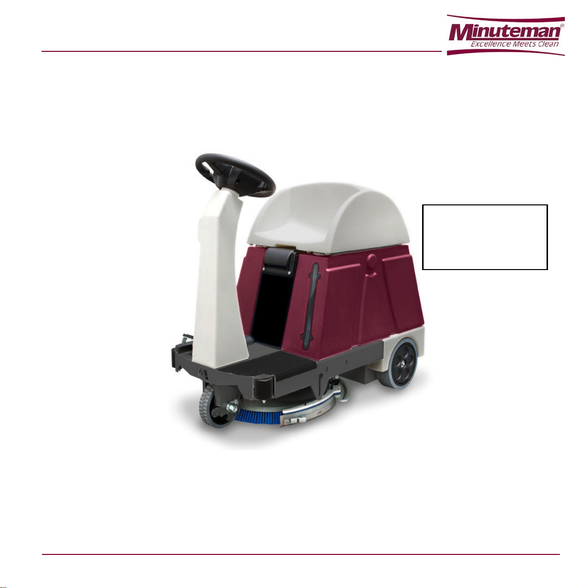
USER AND MAINTENANCE MANUAL
E Ride 21
read the instructions
before using the
Original instructions
Warning:
machine
Minuteman International
14N845 U.S. Route 20, Pingree Grove, IL 60140 Phone: (847) 264-5400 Fax: (847) 683-5207
Web: www.minutemanintl.com
Page 2
Page 3

TABLE OF CONTENTS
CHAPTER 1 INTRODUCTION 1-1
1.1 PURPOSE AND CONTENT OF THE MANUAL 1-1
1.2 TARGET 1-1
1.3 HOW TO KEEP THIS MANUAL 1-1
1.4 IDENTIFICATION DATA 1-2
1.5 OTHER REFERENCE MANUALS 1-2
1.6 SPARE PARTS AND MAINTENANCE 1-2
1.7 MODIFICATIONS AND IMPROVEMENTS 1-2
CHAPTER 2 SAFETY - ACCIDENT PREVENTION 2-1
2.1 SYMBOLS 2-1
2.2 GENERAL INSTRUCTIONS 2-1
2.3 UNPACKING 2-4
CHAPTER 3 MACHINE DESCRIPTION 3-1
3.1 SCRUBBER-DRYER OPERATION 3-1
3.2 AGREEMENTS 3-1
3.3 DESCRIPTION 3-2
3.4 TECHNICAL CHARACTERISTICS 3-7
3.5 ELECTRICAL DIAGRAM 3-9
3.6 ELECTRICAL PROTECTIONS 3-9
3.7 WASH-AND-DRY MACHINE EQUIPMENT 3-9
3.8 OPTIONAL ACCESSORIES 3-9
CHAPTER 4 USE 4-1
4.1 BATTERIES CONTROL / INSTALLATION ON A NEW
WASH-AND-DRY MACHINE 4-1
4.2 BEFORE STARTING THE WASH-AND-DRY MACHINE 4-2
4.3 START UP AND STOPPING OF MACHINE 4-4
4.4 WASH-AND-DRY MACHINE IN OPERATION 4-6
I
Page 4

4.5 AFTER MACHINE USE 4-6
4.6 EMPTYING THE TANKS 4-6
4.7 WASH-AND-DRY MACHINE PUSH/DRAWING MOVEMENT 4-8
4.8 LONG INACTIVITY OF THE WASH-AND-DRY MACHINE 4-8
4.9 FIRST PERIOD OF USE 4-8
CHAPTER 5 MAINTENANCE 5-1
5.1 SCHEDULED MAINTENANCE TABLE 5-1
5.2 SQUEEGEE CLEANING 5-2
5.3 CHECKING/SUBSTITUTION OF THE SQUEEGEE RUBBERS 5-3
5.4 HEIGHT ADJUSTMENT OF SQUEEGEE 5-4
5.5 BRUSH CLEANING 5-4
5.6 CYLINDRICAL BRUSH CLEANING 5-5
5.7 CLEANING THE DETERGENT SOLUTION (OR WATER
FOR WASHING) FILTER 5-6
5.8 CLEANING THE NOZZLE AND FILTER DETERGENT SOLUTION
SUPPLY TO THE DISC BRUSH 5-8
5.9 CLEANING THE NOZZLE AND FILTER DETERGENT SOLUTION
SUPPLY TO THE CYLINDRICAL BRUSHES 5-9
5.10 CLEANING THE DETERGENT FEEDING SYSTEM (OPTIONAL) 5-9
5.11 BATTERY CHARGE 5-10
5.12 CHECKING/REPLACING THE FUSES 5-14
5.13 ASSEMBLY-DISASSEMBLY OF THE SUEEGEE 5-14
5.14 ASSEMBLY-DISASSEMBLY OF THE DISC BRUSH 5-16
5.15 CYLINDRICAL BRUSHES ASSEMBLY-DISASSEMBLY 5-17
CHAPTER 6 SAFETY FUNCTIONS 6-1
6.1 EMERGENCY STOP BUTTON 6-1
6.2 MICROSWITCH OF DRIVER’S SEAT 6-1
CHAPTER 7 TROUBLESHOOTING 7-1
CHAPTER 8 SCRAPPING 8-1
II
Page 5

CHAPTER 1
INTRODUCTION
1.1 PURPOSE AND CONTENT OF THE MANUAL
The purpose of this manual is to provide the User with all
necessary information to use the machine properly in a
safe and autonomous way. It contains information about
technical characteristics, operation, machine inactivity,
maintenance, spare parts and safety conditions.
Before carrying out any procedure on the machine, the
Operators and Technicians in charge of the maintenance
must read this manual carefully. Contact Minuteman in
case of doubts regarding the interpretation of the
instructions and for any further information.
1.2 TARGET
This manual is intended for the Operator and the
Technicians qualified for the machine maintenance. The
operators must not carry out operations assigned to
qualified technicians. Minuteman declines liability for
any damage arising from not observing this prohibition.
1.3 HOW TO KEEP THIS MANUAL
The User and Maintenance Manual must be kept near the machine, inside an adequate case, far from liquids and other substances that can cause damag e to it.
1-1
Page 6
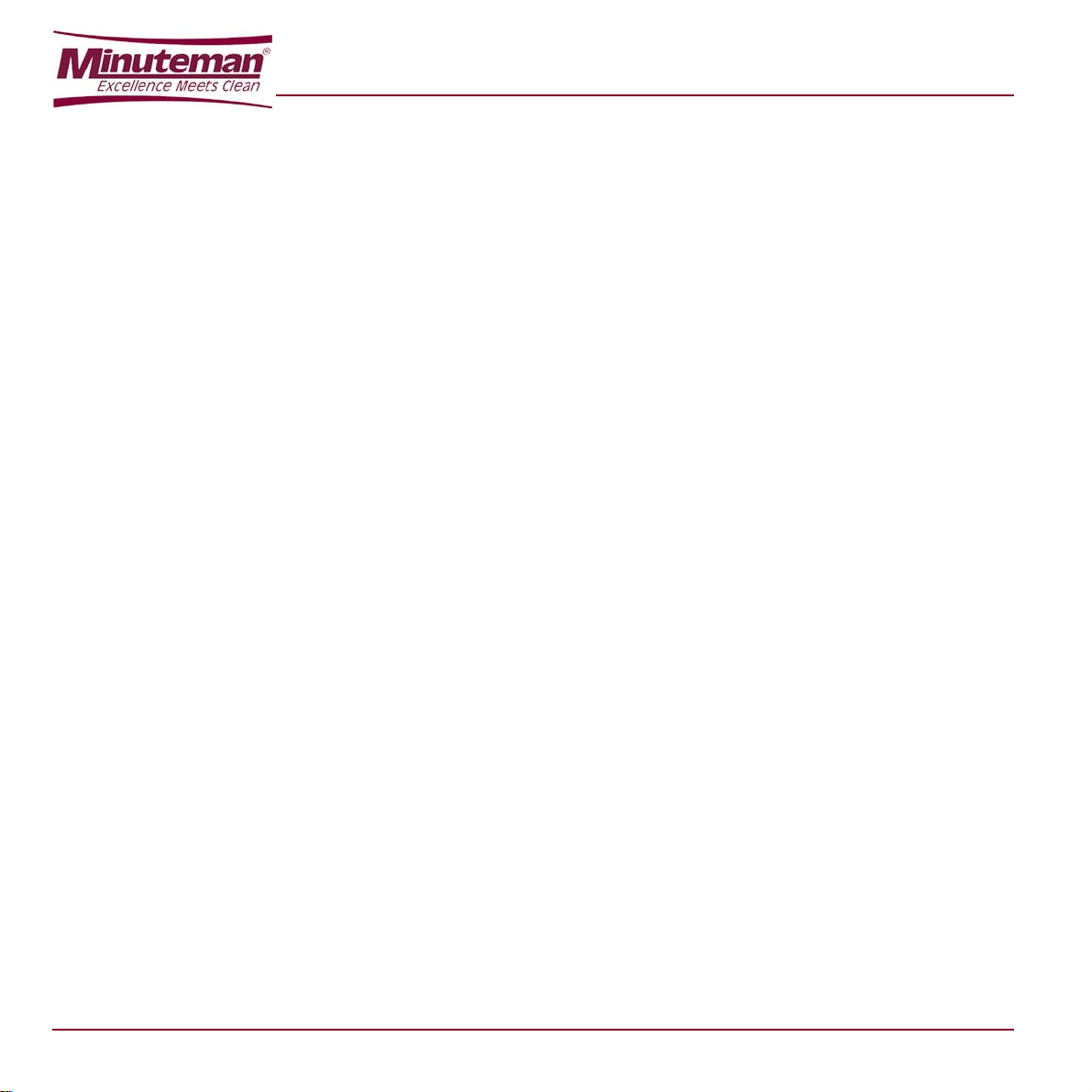
1.4 IDENTIFICATION DATA
1
The Machine Model and Serial Number are marked on the
plate on the frame (battery side) and can be read from
the outside (1, Figure 1-1).
This information is useful when requiring machine
replacement parts. Use the following table to write down
the machine identification data for any further
reference.
MACHINE model:
MACHINE serial number:
1.5 OTHER REFERENCE MANUALS
Moreover, the following manuals are available:
– Service Manual (that can be consulted at any
Minuteman Service Center)
– Spare Part List, supplied with the machine
1.6 SPARE PARTS AND MAINTENANCE
All necessary use, maintenance and repair procedures
must be carried out by qualified personnel or by
Minuteman SERVICE. Only original spare parts and
accessories must be used.
Call Minuteman for service or to order spare parts and
accessories, specifying the machine Model and Serial
Number.
1.7 MODIFICATIONS AND IMPROVEMENTS
Minuteman constantly improves its products and reserves
the right to make changes and improvements at its
discretion without being obliged to apply such benefits to
the machines previously sold.
Any modifications and/or accessory addition must
be a
pproved and performed by Minuteman.
1-2
Figure 1-1
Page 7
CHAPTER 2
SAFETY - ACCIDENT PREVENTION
The following symbols indicate potentially dangerous
situations. Always read carefully this information and take
the necessary precautions to protect people and objects.
Cooperation between the Operator and the machine is
critical. No accident prevention program is effective
without the total cooperation of the pers on re spon sible fo r
the machine operation. Most of the accidents that may
occur in a factory, while working or transferring, are
caused by the failure to comply with the simplest prudence
rules. A careful and prudent user is the best guarantee
against accidents and is the prerequisite to carry out the
prevention program.
2.1 SYMBOLS
DANGER!
Indicates a dangerous situation (risk of
death) for the User.
WARNING!
Indicates the risk for people of being injured
and for objects of being damaged.
CAUTION!
Indicates a caution or a remark related to
important or useful functions. Take care of
the paragraphs marked by this symbol.
READING
Consult the instruction booklet before
performing a determined operation.
2.2 GENERAL INSTRUCTIONS
Specific warnings and cautions to inform about potential damages to people and machine are shown below.
DANGER!
– Disconnect the battery by means of the
appropriate connector before carrying out
any maintenance or repair operation.
– This machine must be used by qualified and
authorized personnel only. Children or
infirm people cannot use this machine.
– Keep the battery far from sparks, flames
and incandescent material. During the
normal operation explosive gases are
delivered.
– Do not wear jewelry when working near
electrical components.
– Do not work under the lifted machine if it is
not securely fixed.
– Do not operate the machine near
dangerous, inflammable and/or explosive
powders, liquids or vapours.
– Battery charging produces explosive
hydrogen gas. Keep the tank assembly
open during battery charging and perform
the operation only in well-ventilated areas
and far from open flames.
2-1
Page 8

WARNING!
– Do not use the machine for purposes other
than those listed in this manual. Use only
accessories recommended by the
manufacturer Minuteman.
– While using this machine take care not to
cause injury or harm to yourself or others.
– Do not let the machine be used as a toy . Pay
special attention when used near children.
– Always protect the machine against the
sun, rain and bad weather, both under
operation and in inactivity condition.
– Do not use the machine as a transport
vehicle.
– Do not leave the machine unattended
without being sure that the machine cannot
move independently.
– Do not leave the machine unattended
without removing the key from its housing.
– Do not use the machine in very dusty areas.
– Do not use the machine on surfaces with a
gradient greater than 6%.
– Do not bump into shelves or scaffoldings, in
particular where there is a risk of falling
objects.
– Do not let any objects obstruct the
air pathways. Do not use the machine if the
pathways are blocked; always keep the air
pathways free from dust, debris, and other
materials which could reduce the air flow.
– To avoid the risk of electric shock, do not
expose the machine to rain. Store the
machine indoors.
– Do not remove or modify the plates affixed
on the machine.
– The machine working temperature must be
within 0°C - +40°C.
– Storage temperature must be within 0°C -
+40°C.
– Humidity range should be within 30% and
95%.
– In case of machine malfunctions, review
Chapter 5 (Maintenance) and 7 (Troubleshooting). Otherwise, request
assistance from an authorized Minuteman
service Dealer.
– Carefully read all maintenance/repair
instructions before carrying out any
maintenance/repair procedure.
– Do not tamper with the machine safety
guards; For your safety, only follow the
recommended maintenance i
o not wash the machine with pressurized
– D
water, or with cor rosive substances.
– Before using the battery charger, be sure
that frequency and voltage value s indicated
in the specific Manual correspond to the
system values.
– Do not recharge the batteries if the power
cord or plug is damaged.
– Do not smoke during battery charging.
– To reduce the risk of fire, electric shock or
injury , do not leave the machine charging for
for long periods of time. Unplug
machine from the wall outlet when not in
use and be
fore maintenance.
nstructions.
when connected e
2-2
Page 9

– Do not use the battery charger cable for
hauling or transporting the machine. Do not
let the power cord being crushed by a door,
pull it over surfaces or sharp corners. Do
not run with the machine over the power
cord. Keep the cord away from hot
surfaces.
– If the machine is not working properly,
damaged, left outdoors or dropped into the
water, ask for the intervention of a service
center Minuteman.
– Take all necessary precautions to prevent
hair, jewels and loose dresses from being
caught by the machine moving and suction
parts.
– If parts must be replaced, require
ORIGINAL spare parts from a Dealer or
Authorized Retailer.
– To ensure the machine proper operation
and safety conditions, the authorized
personnel or the Service Center must carry
out the Scheduled Maintenance detailed in
the related chapter of this Manual.
– If the machine is used according to the
instructions, the vibrations do not cause
dangerous situations. The machine
vibration level is under 2.5 m/s2.
– This machine cannot be used on roads or
public streets.
– Pay attention to the machine transfers when
temperature is under freezing point. The
water in the recovery tank or in the pipes
could freeze and damage the machine.
– Use the brushes and the disks supplied with
the machine and those specified in the
Instruction Manuals. Using other brushes or
disks could reduce safety.
– If lead-acid batteries (WET) are installed in
the machine, do not tilt the machine over 30
° to the horizontal plane, to avoid the highly
corrosive liquid escapes from the battery.
When you need to tilt the machine for
maintenance, remove the battery
beforehand.
– The machine must be not abandoned, at
the end of its useful life, because of the
presence of toxic-harmful materials (battery
acid, oil, etc.), which are subject to
standards that require disposal in special
centers (see chapter "Scrapping").
2-3
Page 10

2.3 UNPACKING
To unpack the Machine carefully follow the instructions on
the packing.
When the machine is delivered, check that the packing and
the machine were not damaged during transportation. If
the damage is evident, keep the packing and have it
checked by the Parcel Service that delivered it. Call the
Parcel Service immediately to fill in a request for a
compensation for damages.
Please check that the following items have been supplied
with the machine:
1. Technical documents:
– Scrubber-dryer Use and Maintenance Manual
– Spare Part List
2. ........
2-4
Page 11
CHAPTER 3
MACHINE DESCRIPTION
3.1 SCRUBBER-DRYER OPERATION
The scrubber-dryer is used to clean (washing and drying)
smooth and solid floor, in civil or industrial environment,
under safe operation conditions by a qualified Operator.
The scrubber-dryer cannot be used for fitted carpet and
carpet cleaning.
3.2 AGREEMENTS
Forward, backward, front, rear, left or right are int ended
with reference to the operator’s position with the operator's
hands on the handlebar (12, Figure 3-2).
3-1
Page 12

3.3 DESCRIPTION
Control panel and controls
(See Figure 3-1)
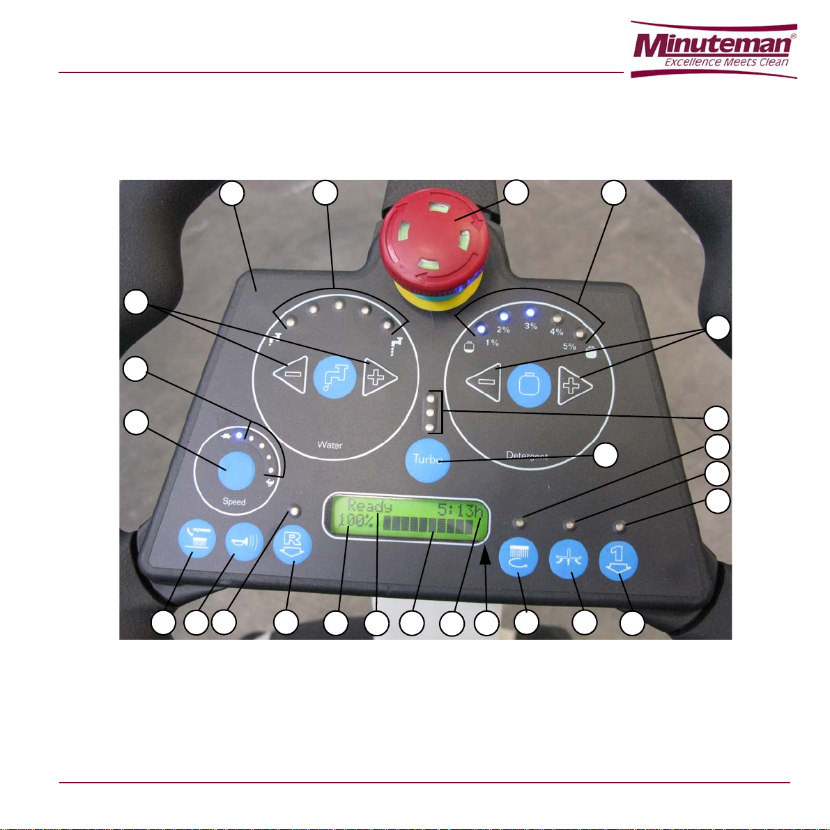
1. Control panel and controls
2. Emergency stop button
3. Display, indicating: 3a. “READY”: wash-and-dry machine ready, or “SIT
DOWN”: sit on the seat
3b. Total hours of work
3c. Battery state of charge in %
3d. Battery state of charge in graphic scale
4. Adjustment buttons (+ and -) of the deterge nt solution flow (or of the water for washing) (*)
5. Light indication of the detergent solution flow (or water for washing)
6. Adjustment buttons (+ and -) of the detergent percentage according to washing water (optional) (*)
7. Light indication of the detergent percentage (optional).
8. 30-second turbo button for activating the maximum detergent solution and detergent flow (or water for washing).
9. 30-second light indication.
10. Adjustment button of the maximum wash-and-dry machine speed (*)
11. Wash-and-dry machine instantaneous speed light indication
12. Button for activating the lowering and rotation of the disc brush (or cylindrical brushes)
13. Activated disc brush (or cylindrical brushes) light indication; the light indication blinks during the passage from de-activated to activated and vice versa
14. Button for activating the lowering of the squeegee and water recovery suct ion.
15. Activated squeegee and suction light indication; the
light indication blinks during passing from deactivated to activated and vice versa
16. Simultaneous activation button f or both the squeegee and suction and the disc brush (or cylindrical brushes).
17. Activated squeegee, suction and disc brush (or cylindrical brushes) light indication; the light indication blinks during passing from de-activated to activated and vice versa
18. Button for activating the reverse motion.
Speed is halved compared to the forward motion
An attention sound signal is activated for the activation
time of the reverse motion
19. Reverse motion activated light indication
20. Button for activating the sound attention sound signal.
21. Button for releasing the disc brush.
(*): On starting the wash-and- dry machine through the key, these adjustments are set on previous values.
3-2
Page 13
11
10
12
1418
3c
3a
3d
3b
21
20
3
7
6
13
15
17
9
19
16
4
2
5
1
8
Figure 3-1
3-3
Page 14
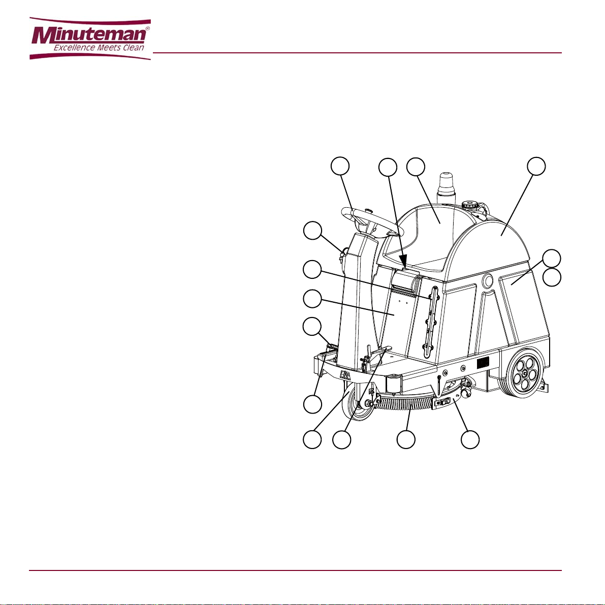
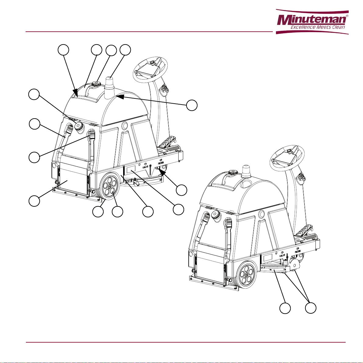
External views
11
10a
10b
(See Figure 3-2 and Figure 3-3)
1. Steering-wheel
2. Ignition key: 0: off I: on
3. Pedal for starting motion and acceleration
4. Detergent solution (or water for washing) level indicator
5. Front drive and steering wheel
6. Rear wheels
7. Disc brush
8. Cylindrical brushes
9. Squeegee 10a. Detergent solution (or water for washing) tank 10b. Water recovery tank
11. Tank covers
12. Operator’s seat
13. Detergent tank with handle (optional)
14. Detergent tank stopper
15. Detergent solution (or water for washing) tank stopper
16. Water recovery waste pipe
17. Detergent solution (or water for wash ing) waste pipe
18. Battery-holder case
19. Blinking light (optional)
20. Drinks-holding container (usable only if the blinking light is not installed)
21. Object-holding container (usable only if the detergent tank is not installed)
22. Protection panel of the electric-electronic compartment
23. Detergent solution (or water for washing) filter
24. Identification plate / technical data / CE marking
25. Tanks cover lifting handle
26. Heel cushion
27. Rear wheel cover
28. Rear wheel mudguard
29. Emergency and parking brake
2
4
22
3
26
5
1
29
25
12
7
Figure 3-2
9
3-4
Page 15
19
14
1321
15
16
17
18
27 28
20
9
6
8
24
23
Figure 3-3
3-5
Page 16
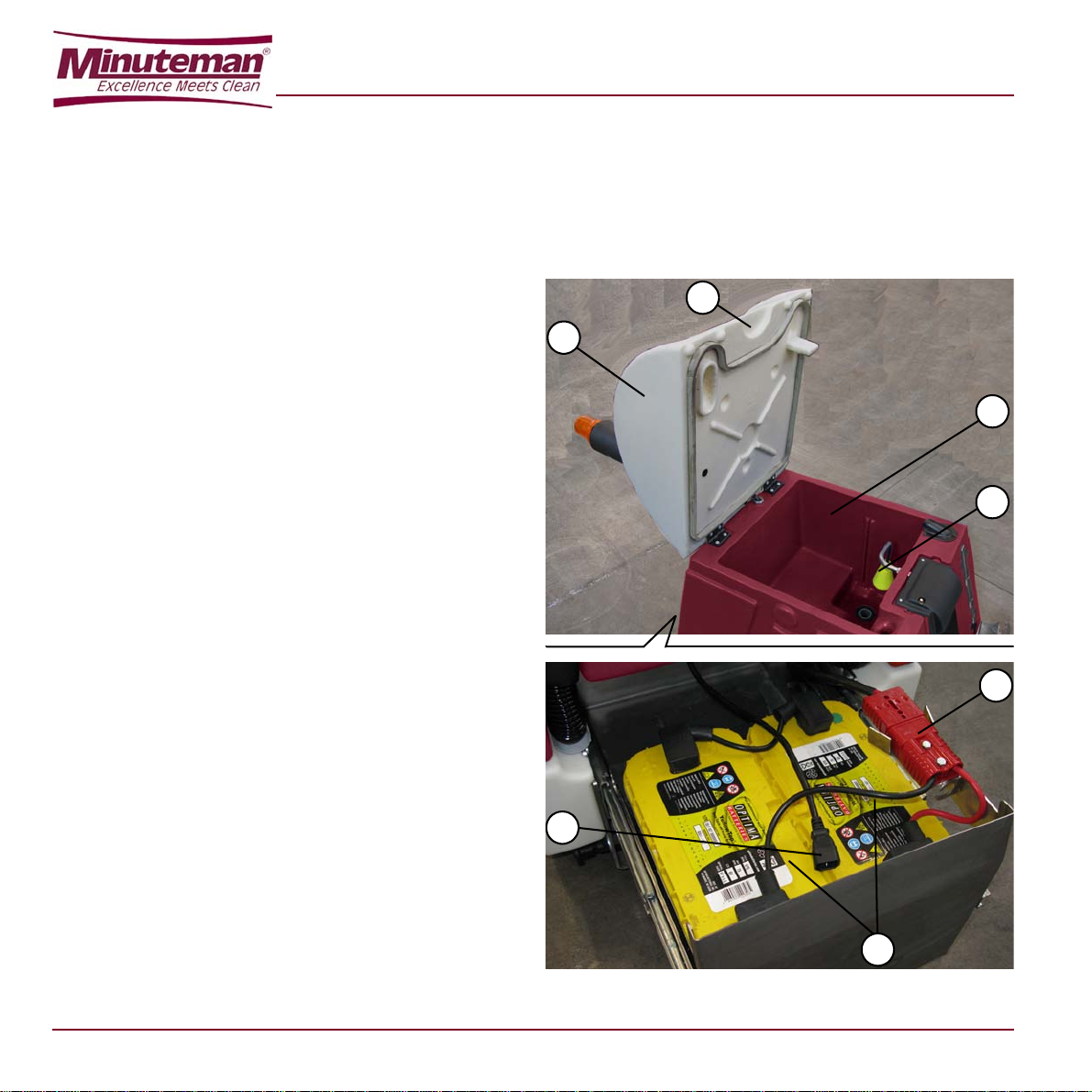
Internal parts view
1
2
3
4
7
5
6
(See Figure 3-4)
1. Tank covers (in uplifted position)
2. Handle for cover opening
3. Water recovery tank
4. Float for full water recovery tank
5. Batteries
6. Batteries connector
7. Battery charger connector of wash-and-dry machine for connection to the electric network (optional)
Figure 3-4
3-6
Page 17

3.4 TECHNICAL CHARACTERISTICS
Description
Voltage 24V 24V
Washed path 53 cm 51 cm
Suction 1168 mm H
Detergent solution tank (or water for washing), capacity 55 L 55 L
Water recovery tank, capacity 55 L 55 L
Disc brush revolutions 175 rpm Cylindrical brush revolutions - 830 rpm
Number of disc brushes 1 Number of cylindrical brushes - 2
Disc brush pressure 23 Kg Cylindrical brushes pressure - 25 Kg
Washing speed 3-5 Km/h 3-5 Km/h
Maximum speed 5 Km/h 5 Km/h
Maximum floor inclination for using the wash-and-dry machine 6 % 6 %
Maximum overcoming inclination of the wash-and-dry machine drive during
transfers
No. Batteries 2 – 110 Ah 2 – 110 Ah
Inbuilt battery charger Yes (optional) Yes (optional)
Theoretical hour yield 2120 mq/h 2040 mq/h
Estimated hour yield 1270 mq/h 1220 mq/h
Endurance 2.30 h 2.30 h
MIT (Minuteman Injection Tecnology) Yes Yes
MIT, flow 0,4-3,8 L/min 0,4-3,8 L/min
MCS (Minuteman Chemical System) Optional Optional
MCS, ratio 1-5 % 1-5 %
Wash-and-dry machine passage width 65 cm 65 cm
E Ride 21
(with one disc brush)
2
O 1168 mm H2O
25 % 25 %
E Ride 21
(with two cylindrical
brushes)
3-7
Page 18

Description
Wash-and-dry machine body dimensions, with squeegee and brush (length x
height x width)
Wash-and-dry machine net weight (without batteries, with empty tanks,
without driver)
Wash-and-dry machine gross weight (with batteries, with one full tank,
without driver)
Drive motor 400 W 400 W
Disc brush motor 400 W Motor cylindrical brushes - 600 W
Motor suction 400 W, 3 stages 400 W, 3 stages
Manufacturing Regulations CE CE
Protection class IPX 4 IPX 4
Level of acoustic pressure A at working position 72.4 dB (A) 72.4 dB (A)
Level of acoustic power A 87.6 dB (A) 87.6 dB (A)
E Ride 21
(with one disc brush)
1200 x 1130 x 600 mm 1200 x 1130 x 600 mm
148 Kg 145 Kg
~ 250 Kg ~ 247 Kg
E Ride 21
(with two cylindrical
brushes)
3-8
Page 19

3.5 ELECTRICAL DIAGRAM
Refer to the Service manual.
3.6 ELECTRICAL PROTECTIONS
Fuses
– The following fuse (22, Figure 3-2) is placed under
the panel:
– Fuse (F3) for protecting auxiliary services (10
A): (2, Figure 4-2)
For the other fuses present on the wash-and-dry m
refer to the Service manual
achine,
3.7 WASH-AND-DRY MACHINE EQUIPMENT
The wash-and-dry machine is supplied with the following equipment versions:
STD Version:
– with squeegee
– without disc brush (or cylindrical brushes)
– without batteries
– without electronic battery charger onboard
B Version:
– with squeegee
– without disc brush (or cylindrical brushes)
– with batteries
– without electronic battery charger onboard
OBC Version:
– with squeegee
– with disc brush (or cylindrical brushes)
– without batteries
– with electronic battery charger onboard
COMPLETE Version:
– with squeegee
– with disc brush (or cylindrical brushes)
– with batteries
– with electronic battery charger onboard
DELUXE Version:
– with squeegee
– without disc brush (or cylindrical brushes)
– without batteries
– without electronic battery charger onboard
– with heel cushion (26, Figure 3-2)
– with wheel covers for rear wheels (27, Figure 3-3)
– with wings for rear wheels (28, Figure 3-3)
in addition:
The batteries can be of the following types:
– lead (WET)
–GEL
–AGM
3.8 OPTIONAL ACCESSORIES
Cylindrical brushes of different materials compared to the
standard ones.
Oil-proof squeegee rubber blades.
Front and rear wheels of different materials
Washing detergent feeding system (MCS)
Blinking light.
Filling the detergent solution (or water for washing) tank
extractable hose.
Filling the detergent solution (or water for washing) tank
quick connection.
For further information on the wash-and-dry m
equipment and the above optional accessories, refer to
your trusted Dealer.
achine
3-9
Page 20

3-10
Page 21

CHAPTER 4
WARNING!
On some points of the machine there are
some adhesives indicating:
–DANGER
–WARNING
–CAUTION
–CONSULTATION
By means of this Manual, the operator must learn the
meaning of these symbols.
Do not cover these plates for any reason, in case of
damage replace them immediately.
4.1 BATTERIES CONTROL /
INSTALLATION ON A NEW WASHAND-DRY MACHINE
ATTENTION
The electric components of this machine can
be seriously damaged if batteries are either
installed or connected improperly. Batteries
can be installed by qualified personnel only.
Set the machine electronic board and the
integrated battery charger according to the
type of batteries used (WET, GEL, AGM
batteries).
Check the batteries for damage before
installation.
Disconnect the battery connector or the
battery charger plug.
Move the batteries with great care.
Install the battery terminal protection caps
supplied with the machine.
USE
Alternatively, the wash-and-dry machine requires:
– 2 12V, 110 Ah (WET) batteries
– 2 12V, 110 Ah (GEL) batteries
– 2 12V, 110 Ah (AGM) batteries
The machine can be supplied as follow:
a) WET or GEL or AGM batteries supplied and
already installed on the machine and ready to be
used
b) Without batteries
According to these conditions, operate as described
below.
a) WET or GEL or AGM batteries supplied and
already installed on the machine and ready to be
used
1. The machine is ready to be used.
b) Without batteries
2. Buy appropriate batteries (See paragraph
"Technical Characteristics" Apply to battery
qualified retailers to choose and install the
battery.
3. Install and set the machine batteries Service
Manual according to the type of battery, as
described in the following paragraph.
4-1
Page 22

4.2 BEFORE STARTING THE WASHAND-DRY MACHINE
General control
1. Visually check that the wash-and-dry m
good conditions; check that the disc brush (1,
Figure 4-1) (or the cylindrical brushes) and the
squeegee (2) are present and in good conditions.
Control of water recovery tank
2. Raise the cover (3, Figure 4-1) with its handle and
check that the water recovery tank is empty,
otherwise proceed with the emptying by acting as
described in the related paragraph “tanks emptying”.
Water filling of the detergent solution (or water for washing) tank
– The tank can be filled in one of the following ways,
according to the version of the nozzle pr esent on the
wash-and-dry m
achine.
3. (Basic version)
Unscrew the stopper (4, Figure 4-1), then introduc e
water through its nozzle (5).
Once the filling is completed, screw the stopper (4).
4. (Version with extractable hose)
Unscrew the stopper (4, Figure 4-1), then extract the
extractable hose (6) and position its opening (7)
under a water tap and fill the tank. Once the filling is
completed, insert the extractable hose in its place (6,
Figure 4-1) and screw the stopper (4).
5. (Version with quick connect stopper) Connect the
water pipe equipped with a proper quick connection
to the stopper (9) quick connection (8, Figure 4-1),
then open the pipe tap, and let the wa ter flow into the
tank. Upon reaching the full tank, the water flow will
achine is in
be stopped automatically by the quick connection (8).
Remove the water pipe from the quick connect ion (8).
ATTENTION!
The water temperature in the tank must not exceed
40 °C (100°F)
Addition of detergent in the water for washing tank
(Only for the version without automatic detergent
feeding system (MCS))
6. If present, remove the stopper (4, Figure 4-1) and
add the detergent to the clean w ater present in the
tank; follow the dilution instructions indicated on the
label of the detergent container itself.
If the tank is too full, let enough water to flow out so
to add the detergent.
ATTENTION!
Use a proper detergent for the type of
cleaning to be carried out. Use exclusively
low foaminess and non-inflammable liquid
detergents; suitable for the wash-and-dry
machine to be used.
Filling of the detergent tank (Only for the version with automatic detergent feeding system (MCS))
7. If necessary, it is possible to remove th e detergent
tank from the wash-and-dry m
achine (10, Figure 4-1),
by seizing its handle (11) and raising it.
8. Unscrew the stopper (12).
9. Introduce the washing detergent into the tank (10, Figure 4-1), then screw the stopper (12).
10. If removed, reinsert the tank (1 0, Figure 4-1) to its
place in the wash-and-dry m
achine.
4-2
Page 23

5
12
11
10
4
3
2
8
7 6
9
1
ATTENTION!
Use a proper detergent for the type of
cleaning to be carried out. Use exclusively
liquid detergents with low foaminess and
non-inflammable; suitable for the wash-anddry machine to be used.
Figure 4-1
4-3
Page 24

4.3 START UP AND STOPPING OF MACHINE
Start up
1. Prepare the machine as envisaged in the previous
paragraph.
2. Seat up on the machine seat (7, Figure 4-2).
3. Turn the start up key (1, Figure 4-2) on “I”; wait a few
seconds until on the display (3) appears the machineis-ready caption (4) “READY”.
ATTENTION!
Do not turn the start up key (1) without first
seating on the seat (7), si nce a safety system
consents use of the machine only when the
operator is seated on the machine seat (7).
It is absolutely forbidden to try to mi shandle
the above-mentioned seat safety system, or
simulate in any way seating of the operator
on the seat.
In the event that the start up key is turned (1,
Figure 4-2) without being seated on the seat, in the
display area (4) appears caption "SIT DOWN" and no
function of the machine is available.
When the display shows indications other than those
described, it is necessary to request action by the
Minuteman Assistance Service.
4. Check the state of the battery charges by observing
the percent indication (5, Figure 4-2) and the graphic
indication (6).
If necessary proceed in charging the batteries; see
specific paragraph of chapter Maintenance.
ATTENTION!
The machine is not suitable to be used on
ruined, uneven floors.
5. Go to the workplace, by starting up th e m ac hin e wit h
the hands on the steering wheel and by pressing the
pedal (2, Figure 4-2).
The speed of moving is adjustable from zero to its
maximum set value, depending on the pressure
exerted on the pedal (2, Figure 4-2)
6. If necessary, through the buttons (8, Figure 4-2) adjust the capacity of the deterg ent solution (or wa ter for washing).
7. (Optional) If necessary, through the buttons (9, Figure 4-2) adjust the percentage of the deterge nt for washing.
8. If necessary, through the button (10, Figure 4-2) adjust the maximum speed of the machine.
9. To start washing the pavement, activate the disc brush (or cylindrical brushes) throu g h t he bu tton (11, Figure 4-2).
10. To start drying of the pavement, activate suction through the button (12, Figure 4-2).
11. To start both washing and drying of the pavement, activate the button (13, Figure 4-2).
12. Start cleaning work by handling through the hands the steering wheel (14, Figure 4-2) and by driving forward the machine by pressing appropriately the pedal (2).
Stopping the machine
13. Release the pedal (2, Figure 4-2).
14. Press the buttons (11, Figure 4-2) or (12) or (13,) to deactivate and lift the respective active operations. Suction stops a few seconds after activation of the related button, for sucking all the water present in the piping.
15. Turn the start up key (1, Figure 4-2) on “0”, and then extract it.
16. If necessary, proceed with emptying the tanks, operating as described in the specific paragraph.
ATTENTION!
Do not leave the machine unattended without
ascertaining that it does not move
autonomously.
Do not leave the machine unattended without
removing the start up key.
4-4
Page 25

17. To stop immediately the machine in the event of an
7
14
1
2
15
8 9
10
11
12
13
4 5 3 6
emergency, press the button (15, Figure 4-2).
To cut out the emergency button (15), turn it
clockwise until unhooking it from the lower position.
Figure 4-2
4-5
Page 26

4.4 WASH-AND-DRY MACHINE IN OPERATION
1. During operation, check the state of the batteries
charge to avoid flat batteries in inaccessible battery
recharge points.
2. Check also periodically the residual quantity of
detergent solution (or water for washing), through its
level indicator.
3. If the water recovery tank fills during use of the wash-
and-dry machine, suction is automatically stopped.
To start suction again, it is necessary to empty the
water recovery tank (see related paragra ph ) .
4. If necessary, at the end of the operation , proceed with
emptying the tanks (see related paragraph).
4.5 AFTER MACHINE USE
At the end of the work, before leaving the machine :
Disconnect the brush in the following way:
1. Empty the tank of water recovery, as listed in the
following paragraph.
2. Clean the disc brush (or cylindrical brushes) and the
squeegee, as listed in the Maintenance Chapter.
3. If necessary, recharge the battery as listed in the
Maintenance Chapter.
4. Leave the machine in a dry and clean place, with
brush and squeegee lifted.
4.6 EMPTYING THE TANKS
Emptying the tank from water recovery
1. Take the wash-and-dry machine to the suitable area
for draining the water recovery, in full compliance of
the anti-pollution regulations in force.
2. Disengage the hose (1, Figure 4-3) from its seat and
raise it beyond the upper edge of the tank until its
area (2) is water free; then, by keeping it in this
position, unscrew the stopper (3).
3. Bend manually the hose in the area (2) until obtaining a watertight fold (17); then, by keeping it bent, lower it on the drain area.
4. Release gradually (in order to avoid undesired squirts) the fold (17) by letting the dirty wate r flow out from the tank into the drain area.
5. With the handle (4, Figure 4-3), raise the cover of the
tanks (5) and, if necessary, wa sh the water reco very
tank (6); wash also the related lower side (7) of the
cover and perimeter gasket (8).
Check that the perimeter gasket (8) is whole: if
damaged, it can jeopardise the good functioning of
the dirty water suction.
WARNING!
Do not damage the float (9, Figure 4-3)
6. Let all the water for washing flow out of the ho se (1, Figure 4-3), then screw the stopper (3) and engage the hose (1) on its seat in the wash-and-dry machine.
Detergent solution (or water for washing) tank emptying
7. Take the wash-and-dry machine to the suitable area for draining the detergent solution (or water for washing), in full compliance of the anti-pollution regulations in force.
8. Disengage the hose (10, Figure 4-3) from its seat and raise it beyond the upper edge of the tank until its area (11) is free from water; then, by keeping it in this position, unscrew the stopper (12).
9. (Only for optional hose that can be pressed in the
area (11)): Bend manually the hose in the area (11)
until obtaining a watertight fold (17); then, by keeping
it bent, lower it on the drain area.
Release gradually (in order to avoid undesired
squirts) the fold (17) by letting the deterg ent solutio n
(or water) flow out from the tank into the drain area.
4-6
Page 27

(Only for the hose that cannot be pressed in t he area
15
14
5
2
11
10
12
16
4
8
7
6
9
5
3
172
1
13
(11)). Lower gradually (in order to avoid undesired
squirts) the hose (10) above the drain area, by letti ng
the detergent solution (or water) flow out from the
tank into the drain area.
10. If necessary, wash the detergent solution (or water
11. Let all the water for washing flow out of the hose (10,
Emptying of the washing detergent tank (Optional)
12. Remove the detergent tank from the wash-and-dry
13. Unscrew the stopper (16) and let the washing
14. If necessary, wash the washing detergent tank.
15. Screw the stopper (16, Figure 4-3) and place the
for washing) tank after unscrewing the stopper (13).
Figure 4-3), then screw the stopper (12) and engage
the hose (10) on its seat in the wash-and-dry
machine.
machine (14, Figure 4-3), by seizing its handle (15)
and raising it.
detergent flow out of the tank in the suitable area for
draining the washing detergent.
tank (14) in its seat in the wash-and-dry machine.
Figure 4-3
4-7
Page 28

4.7 WASH-AND-DRY MACHINE PUSH/
4
3
1
5
3
4
2
DRAWING MOVEMENT
When it is not possible to use the wash-and-dry machine drive, it is possible to move it by pushing it manually.
ATTENTION!
The wash-and-dry machine is not suitable to
be pushed on floors with excessive slopes;
precautions must be taken in advance in
relation to the wash-and-dry machine (gross
weight with 50 liters of water in tanks: about
250 Kg)
4.8 LONG INACTIVITY OF THE WASHAND-DRY MACHINE
If it is intended not to use the wash-and-dry machine for a period longer than 30 days, it is appropriate to perform t he following operations:
1. Carry out what is indicated in paragraph "After Use of
the Wash-and-dry Machine".
2. Empty the detergent solution (or water for washing)
tank by acting as described in the relat ed paragraph.
3. Empty the washing detergent tank (optional) by
acting as described in the related paragraph.
4. Disconnect the connector of the batteries, by acting
as described further down.
Remove the left pin (1, Figure 4-4), then rotate it by
half turn, and block it in the removed position.
Remove the right pin (2, Figure 4-4), then remove
the battery holder case (3) by the handles (4).
Disconnect the connector (5) of the batteries. Insert
again the battery holder case in its seat ( 3, Figure 4-
4) and let it engage to the retain er (2) and re tainer (1)
after unblocking it.
5. Clean the detergent feeding system (optional), by
acting as described in chapter “Maintenance”.
4.9 FIRST PERIOD OF USE
After the first period of use (first 8 hours) it is n ecessary t o check that the fixing and connecting elements are correct ly fixed, that the visible parts are integral and that there are no leakages.
Figure 4-4
4-8
Page 29

CHAPTER 5
MAINTENANCE
The machine proper and safe operation is guaranteed by
a careful and constant maintenance.
The following table sums up the scheduled maintenance.
This Manual contains the Scheduled Maintenance Table
and describes only the easiest and most common
maintenance procedures.
The indicated periods can be subjected to variations
according to working conditions. These must be defined by
the person in charge for the maintenance.
REMARK:
For other maintenance procedures containe d
in the Scheduled Maintenance Table see the
WARNING!
The operations must be carried out with the
specific “Service Manual” that can be
consulted at any Service Center.
machine off and the battery disconnected.
Moreover, read carefully the instructions in
the Safety chapter before performing any
maintenance operation.
All periodic or extraordinary maintenance operations must be performed by skilled personnel, or by an authorized Service Center.
5.1 SCHEDULED MAINTENANCE TABLE
Daily, after using the
Operation
Squeegee cleaning
Disc brush cleaning (or cylindrical brushes)
Battery charge
Squeegee rubber blades check/replacement
Cleaning of the detergent solution (or water for washing) filter
Cleaning of nozzles and filters
Screws and nuts tightening check (1)(2)
Check of HEPA suction filter (2)
Brushes rotation belt check/replacement (2)
Drive chain check/replacement (2)
wash-and-dry
machine
Monthly or
every 100
hours
Half-yearly or
every 400
hours
Yearly or every
800 hours
(1): and after the first 8 working hours
(2): maintenance, falling within the competence of a Minuteman Authorized Service Center
5-1
Page 30

5.2 SQUEEGEE CLEANING
2
2
5
1
3
4
1
NOTE
To obtain a good floor drying, the squeegee
must be cleaned and the rubber blades must
be in good conditions.
ATTENTION!
The use of work gloves is recommended
during the squeegee cleaning due to the
possible presence of sharp debris.
1. If necessary, remove the squeegee (See procedure in the related paragraph).
2. Wash and clean the squeegee (1, Figure 5-1); in
particular, clean the dirt and debris in the spaces (2)
and hole (3). Check that the front rubber blade (4)
and the rear rubber blade (5 ) are whole and do not
show cuts or tears, otherwise replace them (see
procedure in the related paragraph).
3. If removed, replace the squeegee (See procedure in the related paragraph).
5-2
Figure 5-1
Page 31

5.3 CHECKING/SUBSTITUTION OF THE
3
6
7
5
7
5
4
6
8
2
9
1
SQUEEGEE RUBBERS
1. Disassemble and clean the squeegee, by operating as described in the specific paragraph.
2. Check that the fron t rubber (1, Figure 5-2) and the
rear rubber (2), are whole and are without cuts and
tears, otherwise substitute t hem, as describe d below.
Check also that the front edge (3) of the rear rubber
(2) is not worn out; otherwise turn upside-down this
rubber, by bringing in its place one of the other three
edges, if still whole. Should also the other three
edges be worn out, substitute the rubber, by
operating as described below:
– Substitute (or turn upside-down) the re ar rubb er
– Substitute the front rubber (1, Figure 5-2) after
3. Refit the squeegee by operating as described in the specific paragraph.
4. If necessary, carry out the height Adjustment of the squeegee by operating as described in the following paragraph.
(2, Figure 5-2) after having released the stop
(4), unhooked the eccentric (5), and removed
the stop band (7) by releasing them from the
dowels with nut (6); finally, refit the rubber by
operating in reverse order with respect to the
removal.
having unscrewed the nuts (8) and removed the
stop band (9); finally, refit la rubber by op erating
in reverse order with respect to the removal.
Figure 5-2
5-3
Page 32

5.4 HEIGHT ADJUSTMENT OF
2
1
1
3
2
SQUEEGEE
– The adjustment of the squeegee height is necessary
when the wash-and-dry machine does not provide
correct drying, leaving trails of water in the central or
external parts.
1. To adjust the squeegee height, loosen the nuts (1, Figure 5-3) and adjust the left and right wheel height (2).
2. At the end of the adjustment, tighten the nuts.
5.5 BRUSH CLEANING
CAUTION!
It is advisable to use protective gloves when
cleaning the disc brush because there can be
cutting debris.
1. If necessary, remove the disc brush (See procedure in the related paragraph).
2. Wash and clean the disc brush (1, Figure 5-4) from dirt and debris
3. If removed, replace the disc brush (See procedure in the related paragraph).
4. The disc brush must be replaced for excessive wear and tear, when in the lowered brush condition, the lateral pins (2, Figure 5-4) lean on the lower ends (3) of the slots.
Figure 5-3
5-4
Figure 5-4
Page 33

5.6 CYLINDRICAL BRUSH CLEANING
2
1
1
2
CAUTION!
It is advisable to use protective gloves when
cleaning the cylindrical brush because there
can be cutting debris.
1. Remove the cylindrical brushes (See procedure in the related paragraph).
2. Wash and clean the cylindrical brushes from dirt and debris.
3. Wash and clean the cylindrical brushes case s too (1 , Figure 5-5). Check that the drive hubs (2) of the cylindrical brushes are free from dirt debris or twisted objects (ropes, etc.).
4. Replace the cylindrical brushes (See pro cedure in the related paragraph).
5. The cylindrical brushes must be replaced for excessive wear and tear, when in the lowered brush condition, the lateral pins (1, Figure 5-5) lean on the lower ends (2) of the slots.
Figure 5-5
Figure 5-6
5-5
Page 34

5.7 CLEANING THE DETERGENT SOLUTION (OR WATER FOR WASHING) FILTER
1. Ascertain that the wash-and-dry machine cannot
move autonomously.
2. By acting on the wash-and-dry machine controls,
lower the squeegee and the disc brush (or cylin dr ical
brushes), then rotate the ignition key on “0” and
extract it (see chapter Use).
3. Close the water/detergent solution flow tap (1,
Figure 5-7) by acting on the right side of the washand-dry machine.
4. Unscrew and remove the filter transparent cover (2).
5. Remove the filter (3) from the transparent cover (4).
6. Clean the filter (3) and the transparent cover (4).
7. Replace the filter (3) in its transparent cover case (4).
8. Screw the filter transparent cover to its seat (2).
9. Open the tap (1).
10. Rotate the ignition key on “I” and wait for the
squeegee and disc brush (or cylindrical brushes)
lifting, then rotate the ignition key on “0” and extract it.
5-6
Page 35

2
2
1
4
3
Figure 5-7
5-7
Page 36

5.8 CLEANING THE NOZZLE AND FILTER
2
1
3
2
3
4
5
DETERGENT SOLUTION SUPPLY TO
THE DISC BRUSH
1. Ascertain that the wash-and-dry machine cannot
move autonomously.
2. Remove the brush (See procedure in the related
paragraph).
3. By acting on the coupling hub (1, Figure 5-8) of the
brush, unscrew the ring nut (2) and recover the
nozzle (3) and the gasket (4).
4. Remove the filter from its seat (5).
5. Clean the nozzle (3) and the filter (5).
6. Replace the filter correctly (5) in its case.
7. Place the nozzle (3) and the gasket (4) in their seat
and then screw the ring nut (2).
8. Replace the brush (See the proced ure in the related
paragraph).
5-8
Figure 5-8
Page 37

5.9 CLEANING THE NOZZLE AND FILTER
2
1
3
4
1
DETERGENT SOLUTION SUPPLY TO
THE CYLINDRICAL BRUSHES
1. Ascertain that the wash-and-dry machine cannot move autonomously.
2. By acting on the wash-and-dry machine controls, lower the cylindrical brushes, then rotate the ignition key on “0” and extract it (see chapter Use).
3. By acting on the front part of the cylindrical brushholder head, unscrew the ring nut (1, Figure 5-9) and
recover the nozzle (2) and the gasket (3).
4. Remove the filter from its seat (4).
5. Clean the nozzle (2) and the filter (4).
6. Replace the filter correctly (4) in its case.
7. Place the nozzle (2) and the gasket (3) in their seat and then screw the ring nut (1).
8. Rotate the ignition key on “I” and wait f or th e lift ing o f the cylindrical brushes, then rotate the ignition key on “0” and extract it.
5.10 CLEANING THE DETERGENT
FEEDING SYSTEM (OPTIONAL)
1. Empty and clean the washing detergent tank, by acting as described in the related paragraph.
2. Put about one litre of clean water into the washing detergent tank.
3. Use the wash-and-dry machine by simulating the washing activity, for the time necessary to clean the detergent feeding system (15-30 minutes), by adjusting the clean water and “detergent” flows t o the maximum values.
4. Finally, remove the residual water from the washing detergent tank.
5. If necessary, perform the other intended procedures “After use of the wash-and-dry machine” (See the related paragraph).
Figure 5-9
5-9
Page 38

5.11 BATTERY CHARGE
Battery charge for wash-and-dry machines with out on board battery charger
CAUTION!
Keep the batteries charged make the ir life last
longer.
CAUTION!
When the batteries are discharged, recharge
them as soon as possible, as that condition
makes their life shorter.
Check for battery charge at least once a
week.
CAUTION!
For machines not equipped with on board
battery charger, the battery charg er must be
appropriate for the battery installed on the
machine.
WARNING!
Battery charging of WET batteries produces
explosive hydrogen gas. Charge the batteries
only in well-ventilated areas and far from
naked flames.
Do not smoke during battery charging.
Keep the tank assembly open while
recharging the battery.
WARNING!
Pay attention during battery recharging
because there can be battery liquid leakage s.
The battery liquid is corrosive. If it comes in
contact with the skin or eyes, rinse
thoroughly with water and consult a
physician.
1. Take the wash-and-dry machine to the area suited for recharging the batteries.
2. Ascertain that the wash-and-dry machine cannot move autonomously. Rotate the ignition key on “0” and extract it.
3. By acting of the rear side of the wash-and-dry machine, remove the left pin (1, Figure 5-10), then rotate it by half turn, and block it in the removed position.
4. Remove the right pin (2 , Figure 5-10) and, carefully, remove completely the battery holder case (3) by the handles (4), then engage the pin (2) on the related locking hole of the extracted case.
5. Only for lead batteries (WET): – check the correct electrolyte level in the
batteries (7, Figure 5-10); if necessary, restore
it through the stoppers (8).
– let all the stoppers (8) open for the next
recharge.
– clean (if necessary) the upper surface of the
batteries.
6. Check the suitability of the battery charger to be used by referring to the instructions of the battery charger itself. The nominal voltage of the battery charger must be equal to 24V.
7. Disconnect the connector of the batteries (5, Figure 5-10).
8. Connect the connector (6, Figure 5-10) to the external battery charger.
9. Connect the battery charger to the electrical network. The charge of the batteries has started.
10. At the end of the recharge, disconnect the battery charger from the electric network and the battery connector (6, Figure 5-10).
11. (only for lead batteries (WET)) Check the correct electrolyte level in the batteries, then close all the stoppers (8, Figure 5-10).
5-10
Page 39

12. Connect again the connector (5, Figure 5-10) to the
8
7
5
6
1
3 2
connector (6).
13. Extract the pin (2) and place the battery case into its seat, then engage the pin (2) to the battery case itself.
14. Unblock and engage the pin (1) to the battery case.
15. The charge has ended.
Figure 5-10
5-11
Page 40

Battery charge for wash-and-dry machines with on
1
2
board battery charger (optional)
1. Take the wash-and-dry machine to the area suited for recharging the batteries.
2. Ascertain that the wash-and-dry machine cannot move autonomously.
3. By acting on the rear side of the wash-and-dry machine, remove the left pin (1, Figure 5-12), then rotate it by half turn, and block it in the removed position.
4. Remove the right pin (2, Figure 5-12) and, carefully, remove completely the battery holder case (3) by the handles (4), then engage the pin (2) on the related locking hole of the removed case.
5. Only for lead batteries (WET): – check the correct electrolyte level in the
batteries (7, Figure 5-12); if necessary, restore
it through the stoppers (8).
– let all the stoppers (8) open for the next
recharge.
– clean (if necessary) the upper surface of the
batteries.
6. Connect the connector (5) to the electrical network,
after checking that the nominal voltage of the network
is that envisaged for the charge of the wash-and-dry
machine (Refer to the technical data plate of the
letter).
The charge of the batteries has started.
9. (only for lead batteries (WET)) Check the correct electrolyte level in the batteries, then close all the stoppers (8, Figure 5-12).
10. Extract the pin (2, Figure 5-12) and place the battery case into its seat; then engage the pin (2) to the battery case itself.
11. Unblock and engage the pin (1, Figure 5-12) to the battery case.
12. The charge has ended.
Figure 5-11
NOTE
When the battery charger is connected to the
network, all the functions of the wash-and-
&
dry machine are automatically excluded.
7. The charge has ended when on the display (1, Figure 5-11) appears “100 %” and all the bars are full (2).
8. Disconnect the electrical connection (5, Figure 5-12) from the network.
5-12
Page 41

2
4
1
7
4
3
5
8
Figure 5-12
5-13
Page 42

5.12 CHECKING/REPLACING THE FUSES
1. Ascertain that the wash-and-dry machine cannot move autonomously.
2. Rotate the ignition key on “0” and extract it.
3. Disconnect the connector from the batteries, by
acting as described further down.
Remove the left pin (1, Figure 5-14), then rotate it by
half turn, and block it in the removed position.
Remove the right pin (2, Figure 5-14), then remove
the battery holder case (3) by us ing the handles (4).
Disconnect the connector of the batter ies (5).
4. Raise the cover (5, Figure 5-15), rem ove the panel (1) by seizing it on the hold (3) and raising it to disengage it from the retainers (4). Close the cover (5).
5. Check / replace the fuses: – 10A Fuse for protecting auxiliary services (2,
Figure 5-15)
6. Place the panel into its seat (1, Figure 5-15) and engage the retainers (4).
7. Connect the connector of the batteries (5, Figure 5-
14).
8. Replace the batteries case to its seat (3, Figure 5-14) and engage it to the retainer (2) an d ret ainer (1) aft er unblocking it.
5. Remove the squeegee (1).
Assembly
6. Assemble in the reverse order with respect to disassembly
3
1 2
Figure 5-13
5.13 ASSEMBLY-DISASSEMBLY OF THE
SQUEEGEE
Disassembly
1. Ascertain that the wash-and-dry machine cannot
move autonomously.
2. Rotate the ignition key on “0” and extract it.
3. By acting of the left side of the wash-and-dry
machine, with the squeegee in raised position, move
slightly the squeegee outwards (1, Figure 5-13), then
loosen its fastening knob (2).
4. Disconnect the suction pipe (3, Figure 5-13) from the
squeegee.
5-14
Page 43

5
3
4
3
1
4
2
4
4
3
1
4
4
2
4
4
5
Figure 5-14
Figure 5-15
5-15
Page 44

5.14 ASSEMBLY-DISASSEMBLY OF THE
8
4
5
3
1
6
2
7
DISC BRUSH
Disassembly
1. Ascertain that the wash-and-dry machine cannot
move autonomously.
2. Sit on the wash-and-dry machine seat and rotate the
ignition key (1, Figure 5-16) on “I”, then wait for a few
seconds so that on the display (3) appears caption (4)
“READY” indicating that the wash-and-dry machine is
ready for use.
3. Press the button (5, Figure 5-16) to release the brush
and wait for a few seconds that the wash-and-dry
machine releases the brush after activating it.
4. Rotate the ignition key (1, Figure 5-16) on “0” and
then extract it.
5. Move slightly the squeegee (6, Figure 5 -16) and
recover the disc brush (7).
Assembly
6. Ascertain that ignition key (1, Figure 5-16) is on “0”.
7. Ascertain that the coupling hub of the disc brush is in
the raised position.
8. Place the disc brush (7, Figure 5-16) below the
wash-and-dry machine, by centring it on the coupling
hub.
9. Sit on the seat and rotate the ignition key (1,
Figure 5-16) on “I”, and wait for a few seconds so
that on the display (3) appears caption (4) “READY”
indicating that the wash-and-dry machine is ready for
use.
10. Press the brush lowering and rotation (8, Figure 5-
16) activation button.
11. Press slightly and only for an inst ant the pedal (2, Fig.
R), by determining the lowering of the hub that will
couple the brush.
In case of non-coupling of the brush, get out of the
wash-and-dry machine and reposition the brush on
the coupling hub which will have remained lowered
(therefore, the alignment operation will be facilitated).
12. Repeat the operations described in the previous points 9, 10 and 11.
13. Rotate the ignition key (1, Figure 5-16) on “0” and then extract it.
Figure 5-16
5-16
Page 45

5.15 CYLINDRICAL BRUSHES
1
1
3
2
1
2
3
1
1
ASSEMBLY-DISASSEMBLY
Disassembly
1. Ascertain that the wash-and-dry machine cannot move autonomously.
2. By operating on the wash-and-dry machine controls, lower the cylindrical brushes then rotate the ignition key on “0” and extract it (see the chapter Use).
3. By operating on the right side of the wash-and-dry
machine, release the retainers and cam (1, Figure 5-
17).
4. Remove the cover (1, Figure 5-18) by disengaging the supports (2) from the cylindrical brushes (3) .
5. Extract the cylindrical brushes (3, Figure 5-19).
Figure 5-18
Figure 5-17
Figure 5-19
5-17
Page 46

Assembly
1 3
12
6. Place the cylindrical brushes in their seat (1, Figure 5-20) by ensuring to engage their pentagonal seat (2) in the related hubs (3).
7. Proceed with the assembly by operating in the reverse order with respect to disassembly.
5-18
Figure 5-20
Page 47

CHAPTER 6
SAFETY FUNCTIONS
The wash-and-dry machine is equipped with safety functions described below.
6.1 EMERGENCY STOP BUTTON
It is placed on the control panel and controls, in positio n (2,
Figure 3-1); it can be easily accessed by the operator; it
must be pressed in situations of immediat e necessity to
stop every function of the wash-and-dry machine. It is
disabled by rotating it clockwise.
6.2 MICROSWITCH OF DRIVER’S SEAT
It is located inside the driver’s seat and does not allow any function of the wash-and-dry machine if the operator is not seating on his seat.
6-1
Page 48

6-2
Page 49

CHAPTER 7
TROUBLESHOOTING
PROBLEM PROBABLE CAUSE SOLUTION
No light indicators light up on the pa nel;
the motors do not work
The water recovery drain is insufficient
The water recovery drain is inexistent
Insufficient flow of the detergent solution
(or water for washing) to the disc brush
(or cylindrical brushes)
Battery connector (5, Figure 3-4)
disconnected
Batteries completely flat Charge them
The emergency stop button (2,
Figure 3-1) re ma in s dep r ess ed
Dirty squeegee (9, Figure 3-2) or worn
out or damaged squeegee rubber
blades
Tank cover not correctly closed or
inefficient gasket (8, Figure 4-3)
The water recovery tank is full. Empty it. Empty it
Flexible hose (3, Figure 5-13)
disconnected from the squeegee.
Dirty detergent solution (or water for
washing) filter (24, Figure 3-2)
Dirty detergent solution (or water for
washing) outlet nozzle
Dirty detergent solution (or water for
washing) tanks Clean it
Connect it
Press it
Clean the squeegee or turn/
replace the rubber blades
Close the cover correctly.
Clean/replace the gasket
Connect it
Clean it
Clean it
Clean it
7-1
Page 50

PROBLEM PROBABLE CAUSE SOLUTION
Lack of detergent solution (or water for
washing) flow to the disc brush (or
cylindrical brushes)
Deficiency/lack of the washing detergent
flow to the disc brush (or cylindrical
brushes)
(For wash-and-dry machine with MCS
optional detergent feeding system)
The squeegee leaves trails of dirt on the
floor
Empty detergent solution (or water for
washing) tank
Obstructed detergent solution (or water
for washing) (2, Figure 5-7) filter
Obstructed detergent solution (or water
for washing) outlet nozzle
Too low percentage (%) of detergent
flow set
Obstructed detergent feeding system
Debris present below the squeegee
rubber blades
Squeegee rubber blades worn out,
chipped, or torn
The squeegee does not contact
correctly
Fill it
Clean it
Clean it
Increase it
Clean it
Clean the squeegee
Turn them/replace them
Adjust the height of the
squeegee contact wheels
Excessively worn out brushes and do
The disc brush (or cylindrical brushes)
does not clean
For further information, contact Minuteman Service Centers, where the Service Manual is available.
7-2
not touch the floor: check.
Check the pins (2, Figure 5-4) or the
pins (1, Figure 5-6)
Replace the brushes
Page 51

CHAPTER 8
SCRAPPING
ATTENTION!
This wash-and-dry machine must not be
disposed of with other household waste at
the end of its lifecycle.
To avoid possible environmental or health
damages caused by an inappropriate waste
disposal, the user is advised to separate this
product from other types of disposals and
recycle it in a responsible manner in order to
favour the sustainable reuse of the material
resources.
Have the machine scrapped by a qualified dismantler.
Before scrapping the machine, remove the following
components:
– Battery
–Brush
– Hoses and plastic parts
– Electric and electronic components
(*): In particular, for scrapping electrical and electronic parts, refer to the local Minuteman Head Offic e.
8-1
Page 52

8-2 Minuteman International - 14N845 U.S. Route 20 - Pingree Grove, IL 60140, USA Rev * 09/13
Phone: 630-627-6900 Fax: 630-627-1130 www.minutemanintl.com A Member of the Hako Group
 Loading...