

Page 1

Para Systems, Inc.
1455 LeMay Dr.
Carrollton, TX 75007
Phone: 1-972-446-7363
Fax: 1-972-446-9011
Internet: minutemanups.com
UPS Sizing: sizemyups.com
Enspire Series UPS
EN750LCD / EN900LCD
User's Manual
PN - 34000496 R1
Page 2

Table Of Contents
1. Introduction 2
2. Controls and Indicators 7
3. Installation 9
4. Operation 12
5. Obtaining Service 15
6. Troubleshooting 16
7. Replacing the Battery 17
8. Specifications 21
9. Limited Product Warranty 23
A1 . Declaration of Conformity 24
1
Page 3

Chapter 1: Introduction
Thank you for purchasing this power protection product. It has been designed
and manufactured to provide many years of trouble free service. Please read
this manual before installing your Enspire Series UPS, models EN750LCD,
EN900LCD as it provides important information that should be followed during
the installation and the maintenance of the UPS system allowing you to correctly set up your system for the maximum safety and performance. Included
is information on customer support and factory service, if it is required. If you
experience a problem with the UPS system please refer to the Troubleshooting
guide in this manual to correct the problem or collect enough information so
that the Technical Support Department can assist you.
IMPORT ANT SAFETY INSTRUCTIONS
SA VE THESE INSTRUCTIONS !
CONSIGNES DE SÉCURITÉ IMPORT ANTES
SAUVEGARDEZ CES CONSIGNES!
CAUTION! This UPS series is ONLY intended to be installed in an indoor tem-
perature controlled environment that is free of conductive contaminants. This UPS
series is not intended for use in a computer room as defined in the Standard for the
Protection of Electronic Computer/Data Processing Equipment ANSI/NFP A 75.
ATTENTION! Cette série d'onduleurs est
dans un environnement intérieur à température contrôlée, exempt de contaminants
conducteurs. La série d'onduleurs ne convient pas pour une utilisation en salle
d'ordinateur comme défini dans la norme pour la Protection des ordinateurs
électroniques/équipements de traitement de données, ANSI/NFP A 75.
CAUTION! Connect the UPS to a two pole, three wire, grounded, utility power AC
wall outlet. The receptacle must be connected to the appropriate branch protection
(circuit breaker or fuse). Connection to any other type of receptacle may result in a
shock hazard and violate local electrical codes. Do not use extension cords, adapter
plugs, or surge strips.
ATTENTION! Branchez l'UPS sur une prise murale c.a. de terre bipolaire à trois
fils. La prise de courant doit être connectée au circuit de protection approprié
(disjoncteur ou fusible). Une connexion à tout autre type de prise peut entraîner le
risque d'électrocution et enfreindre les codes électriques locaux. N'utilisez jamais
de rallonge, d'adaptateur ou de limiteur de surtension.
uniquement destinée à être installée
Veuillez lire ce manuel avant l'installation de l'onduleur modèles EN750LCD,
EN900LCD. Il contient de l'information importante qui doit être respectée au
cours de l'installation et de l'entretien de l'onduleur et des batteries. Cette
information vous permettra de correctement installer le système pour atteindre
son rendement maximum en toute sécurité.
CAUTION! The maximum ambient operating temperature for this UPS series
is 40°C (“0 ~ 40°C” for Ambient Operation).
ATTENTION! La température ambiante de fonctionnement maximale pour
cette série d'onduleurs est de 40° C ("0 ~ 40° C " pour une opération ambiante).
The external vents and openings on the UPS are provided for ventilation.
T o ensure reliable operation of the UPS and to protect the UPS from overheating, these vents and openings must not be blocked or covered. Do not
insert any object into any of the vents or openings that may hinder the ventilation.
Install the UPS system in a well ventilated area, away from excess moistu-
re, heat, dust, flammable gas or explosives.
Leave adequate space (at least 20cm) around all sides of the UPS system
for proper ventilation.
Before usage, you must allow the UPS system to adjust to room temper-
ature (20°C~25°C or 68°F~77°F) for at least one hour to avoid moisture
condensing inside the UPS.
2
CAUTION! T o reduce the risk of fire, connect only to a utility power circuit provided
with 20 amperes maximum branch circuit over-current protection in accordance
with the National Electric Code, ANSI/NFP A 70.
ATTENTION! Pour réduire les risques d'incendie, faites le raccordement
uniquement sur un circuit d'alimentation électrique équipé d'un dispositif de protection de surintensité de circuit de dérivation de maximum 20 ampères, conformément
au Code national de l'électricité, ANSI/NFP A 70.
CAUTION! To reduce the risk of electrical shock with the installation of this UPS
equipment and the connected equipment, the user must ensure that the combined
sum of the AC leakage current does not exceed 3.5mA.
ATTENTION! Pour réduire le risque de choc électrique pendant l'installation de
cet onduleur et du matériel connecté, l'utilisateur doit s'assurer que la quantité de
courant de fuite c.a. ne dépasse pas 3,5 mA.
CAUTION! T o reduce the risk of electrical shock in conditions where the load equipment grounding cannot be verified, disconnect the UPS from the AC wall outlet
before installing a computer interface cable. Reconnect the power cord only after
all signaling connections are made.
ATTENTION! Pour réduire le risque de choc électrique dans une situation où il
n'est pas possible de vérifier la mise à la terre du matériel de charge, il faut d'abord
débrancher l'onduleur de la prise murale c.a. avant d'installer un câble d'interface
ordinateur. Rebranchez le cordon d'alimentation uniquement après que toutes les
connexions de signalisation aient été établies.
3
Page 4
WARNING: This Uninterruptible Power Supply contains potentially hazard-
ous voltages. Do not attempt to disassemble the UPS beyond the battery
replacement procedure. This UPS contains no user serviceable parts. Repairs and battery replacement must be performed by QUALIFIED SERVICE
PERSONNEL ONL Y.
AVERTISSEMENT! Cet onduleur contient des tensions potentiellement
dangereuses. N'essayez pas de le démonter au-delà de la procédure de
remplacement de la batterie. L'onduleur ne contient aucune pièce réparable
par l'utilisateur. SEUL UN TECHNICIEN QUALIFIÉ est autorisé à effectuer
les réparations et le remplacement d'une batterie.
WARNING: Qualified Service Personnel ONLY must perform the Installation and Servicing of these UPS systems. MINUTEMAN accepts no liabilities
and is not limited to: injury to the Service Personnel, or damages to; the UPS,
or the connected equipment caused by the incorrect installation or servicing
of the UPS system.
AVERTISSEMENT! Seul un technicien qualifié peut installer et entretenir
ces systèmes UPS. MINUTEMAN n'accepte aucune responsabilité pour, sans
s'y limiter : les blessures souffertes par le personnel de service ou les dommages
infligés à l'onduleur ou au matériel connecté, résultant d'une mauvaise installation ou d'un entretien incorrect de l'onduleur.
WARNING: Risk of Electrical Shock. Hazardous live parts inside these
power supplies are energized from the battery even when the AC input is
disconnected.
A VERTISSEMENT! Risque de choc électrique. Les parties actives dangereuses
à l'intérieur de ces blocs d'alimentation sont sous tension à partir de la batterie,
même lorsque l'alimentation c.a. est coupée.
T o de-energize the outputs of the UPS:
1. If the UPS is on press and release the On/Off Button.
2. Disconnect the UPS from the AC wall outlet.
3. T o completely de-energize the UPS, disconnect the battery .
NOTE: These UPSs are shipped with the batteries disconnected. The batteries must be connected before putting these UPSs into service. Refer to Section 3 "Installation" for connecting the batteries.
The output of this device is not sinusoidal. It has a total harmonic distortion
and maximum single harmonic as below:
Model
T otal harmonic
Single harmonic
ON / OFF BUTTON: To turn the UPS on: press and hold the
On/Off button until the alarm sounds one beep and then release. Then in aproximately twenty seconds the UPS will perform a five second self-test. Once the UPS has passed its
self-test the UPS will be ready for normal operation. To turn
the UPS off: press and hold the On/Off button until the alarm
sounds one beep and then release.
This equipment has been tested and found to comply with the limits for a Class
B computing device in accordance with the specifications in Subpart J of Part
15 of FCC Rules and the Class B limits for radio noise emissions from digital
apparatus set out in the Radio Interference of the Canadian Department of
Communications. These limits are designed to provide reasonable protection
against such interference in a residential installation. This equipment generates and uses radio frequency and if not installed and used properly , that is, in
strict accordance with the manufacturer's instructions, this equipment may
cause interference to radio and television reception. If this equipment does
cause interference to radio or television reception, which can be determined
by turning the equipment off and on, the user is encouraged to try to correct
the interference by one or more of the following measures:
Reorient the receiving antenna.
Relocate the computer with respect to the receiver.
Move the computer away from the receiver.
Plug the computer into a different outlet so that the computer and receiver
are on different branch circuits.
Shielded communications interface cables must be used with this product.
Changes or modifications to this unit not expressly approved by the party
responsible for compliance could void the user's authority to operate the equipment.
EN750LCD
15.9%
EN900LCD
15.6%
19.4%15.2%
4
5
Page 5
Receiving Inspection
After removing your UPS from its carton, it should be inspected for damage
that may have occurred in shipping. Immediately notify the carrier and place
of purchase if any damage is found. Warranty claims for damage caused by
the carrier will not be honored. The packing materials that your UPS was
shipped in are carefully designed to minimize any shipping damage. In the
unlikely case that the UPS needs to be returned to the manufacturer, please
use the original packing material. Since the manufacturer is not responsible
for shipping damage incurred when the system is returned, the original packing material is inexpensive insurance. PLEASE SA VE THE P ACKING MA TE-
RIALS!
Life Support Policy
As a general policy , we do not recommend the use of any of our products in life
support applications where failure or malfunction of the product can be reasonably expected to cause failure of the life support device or to significantly affect
its safety or effectiveness. We do not recommend the use of any of our products in direct patient care. We will not knowingly sell our products for use in
such applications unless Para Systems receives, in writing, assurances satisfactory to us that (a) the risks of injury or damage have been minimized, (b)
the customer assumes all such risks, and (c) our liability is adequately protected under the circumstances.
© COPYRIGHT 2016 BY PARA SYSTEMS, INC.
All Rights Reserved. All right s of this User Manual (“Manual”), including but not
limited to the content, information, and figures are solely owned and reserved
by Para Systems, Inc. (“Para Systems”). The Manual can only be applied to
the operation or the use of this product. Any disposition, duplication, dissemination, reproduction, modification, translation, extraction, or usage of this
Manual in whole or in part is prohibited without the prior written permission of
Para Systems. Given that Para Systems will continuously improve and develop the product, changes may be made to the information in this Manual at
any time without obligation to notify any person of such revision or changes.
Para Systems will make all possible efforts to secure the accuracy and the
integrity of this Manual. Para Systems disclaims any kinds or forms of warranty, guarantee, or undertaking, either expressly or implicitly, including but
not limited to the completeness, faultlessness, accuracy, non-infringement,
merchantability or fitness for a particular purpose of the Manual.
6
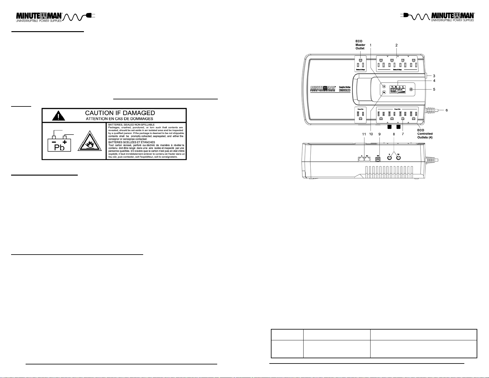
Chapter 2: Controls and Indicators
1. Scroll Button: scroll through the UPS parameters that are available on the LCD
screen.
2. Battery Backup & Surge output receptacles: Mission critical equipment.
3. Input circuit breaker: Protection against an excessive overload.
4. LCD: UPS parameters and warnings.
5. On/Off Button: T urns the UPS On or Off.
6. Input power cord: Connecting to Utility Power.
7. Surge-only output receptacles: Noncritical equipment.
8. Coaxial connectors: for transient voltage surge suppression for cable modem,
CA TV converter or DSS receiver .
9. USB Communications Port: UPS monitoring and control.
10.Alarm Silencer Button: Silences the alarm during the Battery mode.
1 1.RJ1 1/45 Single line Phone/Network protection port.
There will be one ECO Master outlet controlling four ECO Controlled outlets. The
ECO Controlled outlets will turn on when the connected load on the ECO Master
outlet is greater than 12Watts (0.1Amp s). If the load on the ECO Master outlet falls
below 10Watts the ECO Controlled outlets will turn of f. The default setting for the
ECO mode is Disabled.
software.
Model #
EN750LCD
EN900LCD
Input Power Cord
NEMA 5-15P W/6 ft cord
Enable the ECO function by using the power monitoring
Output Power Receptacles
5 - NEMA 5-15R Battery Backup & Surge
5 - NEMA 5-15R Surge Only
7
Page 6

The AC normal icon will be on when the UPS is operating in the
normal AC mode and will turn of f when the UPS is operating in the
Battery mode.
The On-Battery icon will turn on when the UPS is operating in the
Battery mode and will turn off when the UPS is operating in the AC
normal mode.
The Warning/Fault icon will turn on when the UPS detects an internal fault, an Overload, or a Weak/Bad/Disconnected Battery. The
icon will be off when the UPS is operating normally .
The Alarm Silence icon will be displayed when the audible alarm has
been silenced by the Alarm Silencer Button or the monitoring software.
UPS Parameters:
Input - Volt age and Frequency.
Output - Voltage and Frequency .
Estimated Runtime (minutes) - AC normal and Battery mode.
Green Mode Icon - When the Green Mode Icon is on, the UPS is operating at its optimum efficiency level (>90%).
Dual function Bar Graph:
Load Capacity Bar Graph: In the AC mode displays the amount of load
connected to the UPS's Battery Backup & Surge outlets as 20%, 40%;
60%, 80%, 100%.
Battery Capacity Bar Graph: In the Battery mode displays the amount of
battery capacity remaining as 20%, 40%; 60%, 80%, 100%.
The On/Off Button functions as follows:
When the UPS is in the Off position, press and hold the On/Off button
until the alarm sounds one beep and then release to turn the UPS On.
When the UPS is in the On position, press and hold the On/Off button
until the alarm sounds one beep and then release to turn the UPS Off.
The Scroll Button allows the user to scroll through the UPS parameters
that are available on the LCD screen.
Chapter 3: Installation
INSTALLATION PLACEMENT
This UPS series is ONLY intended to be install in an indoor temperature controlled
environment that is free of conductive contaminants. DO NOT operate the UPS in:
extremely dusty and/or unclean areas, locations near heating devices, water or excessive humidity, or where the UPS is exposed to direct sunlight. Select a location,
which will provide good air circulation for the UPS at all times. Route power cords
so they cannot be walked on or damaged. Typical battery life is 3 to 5 years. Environmental factors do affect battery life. High temperatures, poor utility power , and
frequent, short duration discharges have a negative impact on battery life. This
UPS series is not intended for use in a computer room as defined in the Standard
for the Protection of Electronic Computer/Data Processing Equipment ANSI/NFP A
75.
Operating Temperature (Maximum): 0 to 40°C (+32 to +104°F)
Operating Elevation: 0 to 3,000m (0 to +10,000 ft)
Operating and Storage Relative Humidity: 95%, non-condensing
Storage Temperature: -15 to +50°C (+5 to +122°F)
Storage Elevation: 0 to 15,000m (0 to +50,000 ft)
INSTALLATION
(QUALIFIED SERVICE PERSONNEL ONL Y)
Be sure to read the installation placement and all the cautions before installing the
UPS. Place the UPS in the final desired location and complete the rest of the
installation procedure. These UPSs are shipped with the internal batteries disconnected. The batteries must be connected before putting these UPSs into service.
See Connecting the Battery.
These UPSs can be wallmounted.
mount the UPS on the wall. There is a wallmount kit that comes with the UPS. The
kit includes the wallmount template and two wallmount screws. See the Wallmount
T emplate for the wallmount installation instructions.
The primary installation is the Desktop / Office type.
The wallmount configuration allows the user to
When the unit is operating in Battery mode, pressing the Alarm Silencer
Button will silence the audible alarm. Once the UPS reaches the LBW
(Low Battery Warning) threshold the alarm will start beeping. The alarm
cannot be silenced during the LBW alarm. Once the UPS transfers back
to the AC normal mode the alarm will reset back to the default setting.
NOTE: With the exception of the On-Battery alarm all the other Warning/Fault alarms cannot be silenced.
NOTE: The LCD backlight remains on while the UPS is on.
8
CONNECTING THE BATTERY
(QUALIFIED SER VICE PERSONNEL ONL Y)
Please read all of the WARNINGS and CAUTIONS before attempting to connect
the battery .
Use caution the UPS is heavy. Remove the UPS from the shipping box and
1.
set upside down on a desk or a bench top.
NOTE: No tools are required for removing or installing the battery door.
2. Grasp the battery door handle, slide the battery door outward, then lift up-wards
and set aside. (FIG . 1)
9
Page 7

3. Slightly pull the battery module upwards by pulling the pull-tab. (FIG . 2)
DO NOT
pull the battery module out by pulling on the battery wires.
4. Verify proper polarity . Connect the battery negative (Black) wire to the battery
negative (Black) terminal. (FIG 2)
NOTE: Some sparking may occur this is normal.
5. Reinstall the battery module.
6. Reinstall the battery door onto the UPS.
7. Continue with the rest of the Installation.
FIG. 1
FIG. 2
CONNECTING YOUR EQUIPMENT
Plug the mission critical equipment into the Battery Backup & Surge output receptacles on the top panel of the UPS. Plug the noncritical equipment into the Surge
Only output receptacles on the top panel of the UPS. Ensure that the connected
equipment does not exceed the maximum output rating of the UPS (refer to the
information label on the UPS or the electrical specifications in this manual). DO
NOT PLUG EXTENSION CORDS, ADAPTER PLUGS, SURGE STRIPS OR
POWER STRIPS INTO THE OUTPUT RECEPTACLES OF THE UPS, there is a
risk of damaging the UPS and/or connected equipment. DO NOT connect a laser
printer, copier , vacuum cleaner or any other large electrical device into the output of
the UPS.
10
CONNECTING THE UPS TO AN AC SOURCE
CAUTION! T o reduce the risk of fire, connect only to a utility powered circuit with 20
amperes maximum branch circuit over-current protection in accordance with the
National Electric Code, ANSI/NFPA 70. Plug the UPS into a two pole, three wire,
grounded receptacle only . DO NOT PLUG THE UPS INTO EXTENSION CORDS,
ADAPTER PLUGS, SURGE STRIPS OR POWER STRIPS. DO NOT CUT THE
INPUT PLUG OFF AND ATTEMPT TO HARDWIRE THIS UPS, DOING SO WILL
VOID THE WARRANTY .
ATTENTION! Pour réduire les risques d'incendie, faites le raccordement
uniquement sur un circuit d'alimentation électrique équipé d'un dispositif de protection de surintensité de circuit de dérivation de maximum 20 ampères, conformément
au Code national de l'électricité, ANSI/NFP A 70. Branchez l'onduleur uniquement
sur une prise bipolaire à trois fils mise à la terre. NE BRANCHEZ P AS L'ONDULEUR
SUR UNE RALLONGE, UN ADAPT A TEUR, UN LIMITEUR DE SURTENSION OU
UNE BARRE MULTIPRISES. NE COUPEZ JAMAIS LE CONNECTEUR
D'ENTRÉE POUR TENTER DE CÂBLER CET ONDULEUR; CECI ANNULERA
LA GARANTIE.
CHARGING THE BATTERY
The UPS will charge the internal batteries whenever the UPS is connected to an AC
source and there is an acceptable AC volt age present (95 - 140V AC). It is recommended that the UPS's batteries be charged for a minimum of 4 hours before use.
The UPS may be used immediately however, the “On Battery” runtime may be less
than normally expected. Typical battery life is 3 to 5 years. Environment al factors
do affect battery life. High temperatures, poor utility power, and frequent short duration discharges have a negative impact on battery life. NOTE: If the UPS is going
to be out of service or stored for a prolonged period of time, the batteries must be
recharged for at least twenty-four hours every ninety days.
PHONE/FAX/NETWORK PROTECTION CONNECTION (OPTIONAL)
Connect a 10/100 Base-T network, single line phone, or fax line to the RJ11/45
modular connectors on the side panel of the UPS. This connection will require
another length of telephone or network cable. The cable coming from the telephone
service or network system is connected to the port marked “IN”. The equipment to
be protected is connected to the port marked "OUT". NOTE: Connecting to the
Phone/Fax/Network modular connectors is optional. The UPS works properly without this connection.
COAXIAL PROTECTION CONNECTION (OPTIONAL)
Connect a cable modem , CA TV converter or DSS receiver to the coax connectors
on the side of the UPS. This connection will require another coax cable. The cable
coming from the coax service is connected to the port marked “IN”. The equipment
to be protected is connected to the port marked "OUT". NOTE: Connecting to the
coaxial connectors is optional. The UPS works properly without this connection.
POWER MONITORING SOFTWARE
The EN750LCD and EN900LCD support Minuteman's SentryHD power monitoring software. Please go to our web site at www .minutemanups.com/support, then
look under Downloads, and then Software Download Center. Please download
(Free of Charge) the latest version of the Minuteman SentryHD software.
11
Page 8

USB COMMUNICATIONS PORT CONNECTION (OPTIONAL)
The EN750LCD and EN900LCD support USB communications. The power monitoring software and interface cable can be used with the UPS. Use only the interface cable that come with these UPSs. The USB communications protocol is HID.
The HID USB driver comes standard in the Windows OS. Simply connect the USB
cable to the USB communications port on the side panel of the UPS. Connect the
other end of the USB cable to the device that will be monitoring/controlling the UPS
and then follow the prompts on the screen. NOTE: When using the UPS's USB
port with Windows XP , 7, 8 or 10 the Power Options in the Control Panel may need
to be configured. Connecting to the Communications Port is optional. The UPS
works properly without this connection.
Chapter 4: Operation
SYSTEM OVERVIEW
This Standby UPS protect s computers, servers, telecom systems, V oIP systems,
security systems, and a variety of electronic equipment from blackouts, brownouts,
overvoltages, and surges. During normal AC operation, the UPS will quietly and
confidently protect your system from power anomalies.
The UPS will charge the batteries with the UPS in the on or off position as long as
the UPS is plugged into the wall outlet and there is an acceptable AC voltage present
(95 - 140V AC). When a blackout, brownout, or an overvolt age condition occurs;
the UPS will transfer to the battery mode, the On Battery indicator will illuminate and
the audible alarm will sound once every five seconds indicating that the commercial
power is lost or unacceptable. When the commercial power returns or is at an
acceptable level, the UPS will automatically transfer back to the AC normal mode
and start recharging the batteries. During an extended outage when there is approximately two minutes of backup time remaining the audible alarm will sound
twice every five seconds. This Low Battery Warning is informing the user that they
should save all open files, turn off their computer and then turn off the UPS. When
the batteries reach the predetermined level the UPS will automatically shutdown
protecting the batteries from over discharging. Once the commercial power returns the UPS will automatically restart, providing safe usable power to the connected equipment and start recharging the batteries.
Block Diagram of the Basic Wiring and Internal Circuit Configuration
12
TURNING THE UPS ON / OFF
T o turn the UPS on: press and hold the On/Of f button until the alarm sounds one beep
and then release. Then in aproximately twenty seconds the UPS will perform a five
second self-test. Once the UPS has passed its self-test the UPS will be ready for
normal operation. T o turn the UPS off: press and hold the On/Of f button until the alarm
sounds one beep and then release. The UPS will continue to charge the batteries whenever it is plugged into a wall outlet and there is an acceptable AC voltage present (95 140V AC).
ALARM SILENCER BUTTON
When the unit is operating in Battery mode, pressing the Alarm Silencer Button will
silence the audible alarm. Once the UPS reaches the LBW (Low Battery Warning)
threshold the alarm will start beeping. Once the UPS transfers to the AC mode the
alarm will reset to default. NOTE: With the exception of the On-Battery alarm all the
other Warning/Fault alarms cannot be silenced.
SCROLL BUTTON
The Scroll Button allows the user to scroll through the UPS parameters that are available on the LCD screen.
ECO MODE
The ECO mode allows the UPS to save energy by automatically turning off designated
outlets when the connected equipment is turned off or in a standby mode. The default
setting for the ECO mode is Disabled. Enable the ECO function by using the power
monitoring software. There will be one ECO Master outlet controlling four ECO Controlled outlets. The ECO Controlled outlets will turn on when the connected load on the
ECO Master outlet is greater than 12Watts (0.1Amps). If the load on the ECO Master
outlet falls below 10Watts the ECO Controlled outlets will turn of f.
ALARMS
BATTERY MODE
When the UPS is operating in the Battery mode, the AC normal icon will turn off, the OnBattery icon will turn on, the Battery Capacity bar graph will display the battery's capacity
and the alarm will sound one beep every five seconds. Once the UPS returns to the
normal AC mode, the alarm will stop, the On-Battery icon will turn of f and the AC normal
icon will turn on. The audible alarm can be silenced during the Battery Mode alarm.
LOW BATTERY WARNING
When the batteries reach the predetermined level, the alarm will sound two beeps every
five seconds and the Battery Capacity bar graph will flash off/on. This information is to
inform the user that there is approximately two minutes of runtime remaining before the
UPS shuts down. This condition will continue until either AC returns or the UPS’s self
protection circuit shuts the UPS down to protect the battery from over discharging. The
audible alarm cannot be silenced during the LBW alarm.
OVERLOAD
When the amount of load attached to the UPS exceeds its power rating, the Warning/
Fault icon will turn on, the Load capacity bar graph will flash on/off and the alarm will
sound one beep every half a second (AC and Battery modes). This alarm will remain on
until the excess load is removed or the UPS’s self protection circuit shuts the UPS down.
If the UPS has shutdown, remove part of the load and then press the On/Off button to
turn the UPS on. The audible alarm cannot be silenced during the Overload alarm.
13
Page 9

WEAK / BAD / DISCONNECTED BA TTERY
The UPS automatically tests the battery’s condition. If the battery is weak, bad or disconnected, the Warning/Fault icon will turn on, the bar graph frame will flash off/on, and
the alarm will sound three beeps every five minutes until the battery is either reconnected, replaced or passes a self-test. It is recommended that the UPS be allowed to
charge overnight before performing a battery test to confirm a Weak/Bad Battery condition. The audible alarm cannot be silenced during the Weak/Bad/Disconnected Battery
alarm.
UPS FAULT
When the UPS detects an internal fault, the Warning/Fault icon will turn on and the alarm
will sound continuously and the output will be turned off. The Fault condition, in some
instances, may be cleared by turning the UPS off and then back on again. If the Fault
condition does not clear the UPS must be sent in for service. See the Troubleshooting
section. The audible alarm cannot be silenced during the Fault alarm.
LCD ICONS and ALARM FUNCTIONS
Description
AC Mode
Green Mode
ECO Mode
Battery Mode 1-Beep every
AC Normal
Icon
ON
ON
ON
OFF
On-Battery
Icon
OFF
OFF
OFF
ON
Warning / Fault
Icon
OFF
OFF
OFF
OFF
Audible Alarm
OFF
OFF
OFF
5-seconds
Low Battery
Warning
Overload AC
Mode
Overload
Battery Mode
Weak / Bad /
Disconnected
Battery
Internal Fault
OFF
ON
OFF
ON (AC Mode)
OFF (Unit off,
but plugged in)
OFF
ON
OFF
ON
OFF (AC Mode) ON (AC Mode)
OFF (Unit off,
but plugged in)
OFF O N
OFF (Battery
capacity bar graph
will flash off/on)
ON (Load
capacity bar graph
will flash off/on)
ON
ON (Unit off,
but plugged in)
2-Beeps every
5-seconds
1-Beep every
0.5-seconds
1-Beep every
0.5-seconds
3-Beeps every
5-minutes
Constant
Beeping
The unit is off,
OFF
OFF OFF
OFF
plugged into
the wall outlet
and charging
the battery
14
Chapter 5: Obtaining Service
IF THE UPS REQUIRES SERVICE
1. Use the Troubleshooting section to eliminate obvious causes.
2. Verify there are no tripped circuit breakers and that the batteries are good.
A tripped circuit breaker and defective batteries are the most common issues.
3. Call your dealer for assistance. If you cannot reach your dealer, or if they
cannot resolve the issue call or fax the T echnical Support dep artment at the
following numbers; Voice phone (972) 446-7363, F AX line (972) 446-901 1
or visit our Web site at www .minutemanups.com the "Discussion Board".
Before calling the Technical Support Department have the following information available:
a) Contact name and address.
b) Where and when the unit was purchased.
c) All of the model information about your unit.
d) The serial number of your unit.
e) Any information on the failure, including LEDs that may be illuminated
or error codes displayed.
f) A description of the protected equipment including model numbers, if
possible.
g) A technician will ask you for the above information and if possible,
help solve the issue over the phone. In the event that the unit requires
factory service, the T echnical Support Represent ative will issue you a
Return Material Authorization Number (RMA #). NOTE: We must
have the model number and the serial number of the product to
issue an RMA #.
h) If the unit is under warranty, the repairs will be done at no charge. If
the unit is not under warranty there will be a charge for the repair.
4. Pack the unit in its original packaging. If the original packaging is no longer available, ask the T echnical Support Represent ative about obtaining a
new set. It is important to pack the unit properly in order to avoid damage
in transit. Never use Styrofoam beads for a packing material.
a) Include a letter with your name, address, day time phone number,
RMA number, a copy of your original sales receipt, and a brief description of the problem.
5. Mark the RMA # on the outside of all packages. The factory cannot accept
any package without the RMA # marked on the outside of the package.
6. Return the unit by insured, prepaid carrier to:
Para Systems Inc.
MINUTEMAN UPS
1809 W. Frankford Road, Suite 150
Carrollton, TX 75007
A TTN: RMA # _______
15
Page 10

Chapter 7: Replacing the BatteryChapter 6: Troubleshooting
Symptom / Error Code
UPS will not turn on.
UPS operates in battery
mode only , even though
there is AC present.
Low Battery Warning.
UPS does not provide
expected runtime.
The AC normal icon is
illuminated, but there is
no output.
The Warning / Fault
icon is illuminated and
the alarm is sounding
continuously.
The Warning / Fault
icon is illuminated, the
Load bar graph is
flashing and the alarm
is sounding 1-beep every 0.5 seconds.
The Warning / Fault
icon is illuminated, the
bar graph frame is
flashing and the alarm
is sounding 3-beeps every 5 minutes.
Four of the Surge-Only
output receptacles are
off.
Cause / What To Do
Press the On/Off button and release after one beep.
Reset the input circuit breaker by pressing the
plunger back in. If the input circuit breaker trips after the UPS restarts, reduce the load on the UPS.
The UPS's battery reserve is low. This condition will
continue until AC returns or the UPS shuts down from
battery exhaustion.
Charge the batteries for 8-hours and retest. If the
runtime is still less than expected, the batteries may
need to be replaced.
Disconnect the computer cable from the UPS, press
the On/Off button. If UPS works normally, the software had control of the UPS.
The UPS has an internal problem. Call for service.
Check the specifications and remove part of the load.
If the UPS shuts down because of an Overload, re-
move part of the load and then press the On/Off button
to turn the UPS on.
Check the battery connections, charge the batteries
for 8-hours and retest, or replace the batteries.
The ECO function is controlling the output receptacles. Turn on the equipment that is connected to
the Master ECO output receptacle or Disable the ECO
function using the Power Monitoring Software.
REPLACING THE BA TTERY
(QUALIFIED SERVICE PERSONNEL ONL Y)
Please read all of the WARNINGS and CAUTIONS before attempting to ser-
vice the batteries. Typical battery life is 3 to 5 years. Environmental factors
do affect battery life. High temperatures, poor utility power, and frequent,
short duration discharges have a negative impact on battery life.
WARNING! This UPS contains potentially hazardous voltages. Do not attempt to disassemble the UPS beyond the battery replacement procedure.
This UPS contains no user serviceable parts. Repairs and battery replacement must be performed by QUALIFIED SERVICE PERSONNEL ONL Y.
AVERTISSEMENT! Cet onduleur contient des tensions potentiellement
dangereuses. N'essayez pas de le démonter au-delà de la procédure de
remplacement d'une batterie. L'onduleur ne contient aucune pièce réparable
par l'utilisateur. SEUL UN TECHNICIEN QUALIFIÉ est autorisé à effectuer
les réparations et le remplacement d'une batterie.
CAUTION: Do not open or mutilate batteries. Released electrolyte is harmful
to the skin and eyes and may be toxic.
ATTENTION! Évitez d'ouvrir ou d'abîmer les batteries. L'électrolyte qu'elles
contiennent nuit à la peau et aux yeux et peut être toxique.
CAUTION: Do not dispose of batteries in a fire. The batteries may explode.
The batteries in this UPS are recyclable. Dispose of the batteries properly.
The batteries contain lead and pose a hazard to the environment and human
health if not disposed of properly. Refer to local codes for proper disposal
requirements or return the battery to the supplier .
ATTENTION! N'essayez jamais de vous débarrasser d'une batterie en la
brûlant. Elle risque d'exploser. Les batteries de cet onduleur sont recyclables.
Éliminez-les de manière appropriée. Les batteries contiennent du plomb et
posent un danger pour l'environnement et la santé si elles ne sont pas éliminées
de façon appropriée. Consultez les codes locaux pour savoir comment
correctement éliminer une batterie ou renvoyez-la au fournisseur.
16
17
Page 11

CAUTION: The battery system can present a risk of electrical shock. These
batteries produce sufficient current to burn wire or tools very rapidly, producing molten metal. Observe these precautions when replacing the batteries:
1. Remove watches, rings, or other metal objects.
2. Use hand tools with insulated handles.
3. Wear protective eye gear (goggles), rubber gloves and boots.
4. Do not lay tools or other metal parts on top of batteries.
5. Disconnect the charging source prior to connecting or disconnecting the
battery terminals.
6. Determine if the battery is inadvertently grounded. If the battery is, remove
the source of the grounding. Contact with any part of a grounded battery
can result in an electrical shock. The likelihood of such shock will be reduced, if such grounds are removed during installation and maintenance.
ATTENTION! Les batteries peuvent entraîner le risque de choc électrique.
Elles produisent suffisamment de courant pour brûler très rapidement des fils
ou outils, les causant à fondre. Prenez les précautions suivantes lors du
remplacement d'une batterie.
1. Retirez votre montre, bagues ou autres objets métalliques.
2. Utilisez des outils à main à poignées isolantes.
3. Portez des lunettes de protection, des gants en caoutchouc et des bottes.
4. Ne placez jamais des outils ou autres objets en métal sur le dessus d'une
batterie.
5. Déconnectez la source d'alimentation avant de brancher ou de débrancher
les bornes d'une batterie.
6. Vérifiez si, par inadvertance, la batterie est toujours mise à la terre. Si
c'est le cas, supprimez la source de mise à terre. Le contact avec n'importe
quelle partie d'une batterie mise à la terre peut causer un choc électrique.
La suppression de dispositifs de mise à terre pendant l'installation et
l'entretien réduit le risque de chocs électriques.
BATTERY REPLACEMENT PROCEDURE
(QUALIFIED SERVICE PERSONNEL ONL Y)
PLEASE READ THE CAUTIONS AND W ARNINGS BEFORE A TTEMPTING
TO REPLACE THE BA TTER Y MODULE.
Hot-swappable batteries mean that the battery module can be replaced without
powering down the whole UPS system.
NOTE: If there is a power interruption while replacing the hot-swappable
battery module, with the UPS on, the load will not be backed up. To hot-swap
the battery module start with step number 6.
1. T urn off the equipment that is plugged into the output of the UPS.
2. T urn of f the UPS.
3. Unplug the UPS's AC power cord from the AC wall outlet.
4. Unplug the equipment from the output receptacles of the UPS.
5. Unplug all of the cables from the side panel of the UPS.
NOTE: No tools are required for removing or installing the battery door .
6. Grasp the battery door handle, slide the battery door outward, then lift upwards and set aside. (FIG . 1)
FIG. 1
CAUTION: Replace the batteries with the same number and type as originally
installed in the UPS. These batteries have pressure operated vents. These
UPSs contain sealed non-spillable maintenance-free lead acid batteries.
ATTENTION! Remplacez les batteries par des batteries du même numéro et
type que celles d'origine. Une batterie de numéro et type différents peut causer
une explosion. Les batteries sont équipées de purgeurs actionnés par pression.
Les onduleurs contiennent des batteries au plomb étanches et inversables qui
ne requièrent aucun entretien.
EN900LCD
BM0068
18
Model #
Battery Module
Part #
EN750LCD
7. Grasp the pull-tab and pull the battery module upwards. (FIG. 2) DO NOT
pull the battery module out by pulling on the battery wires.
8. Disconnect the battery negative (Black) wire. (FIG. 2)
9. Disconnect the battery positive (Red) wire and set the old battery module
aside. (FIG . 2) Do not short the battery positive wire to the battery negative
wire.
10.Verify proper polarity. Connect the battery positive (Red) wire to the battery po-
sitive (Red) terminal on the new battery module. (FIG 2)
19
Page 12
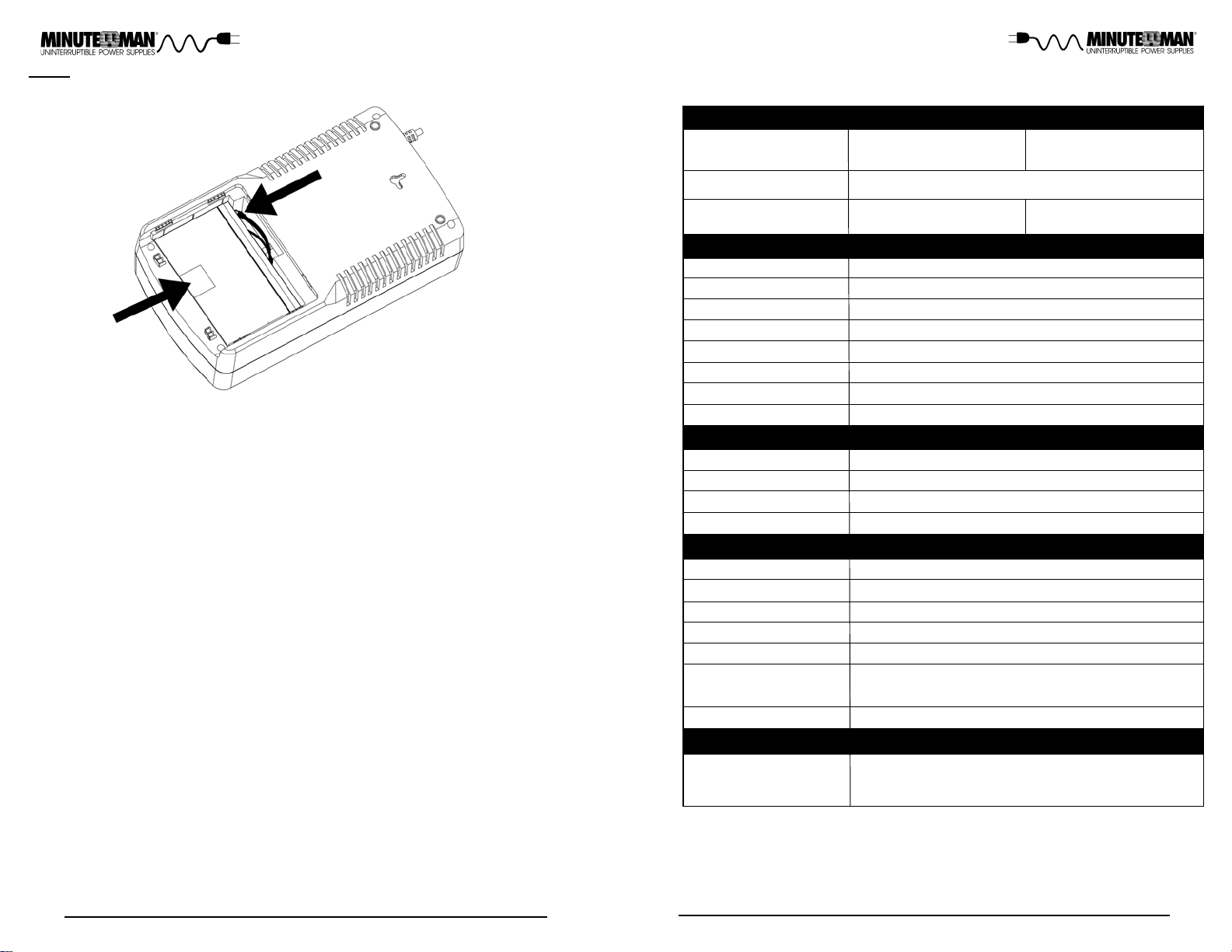
FIG. 2
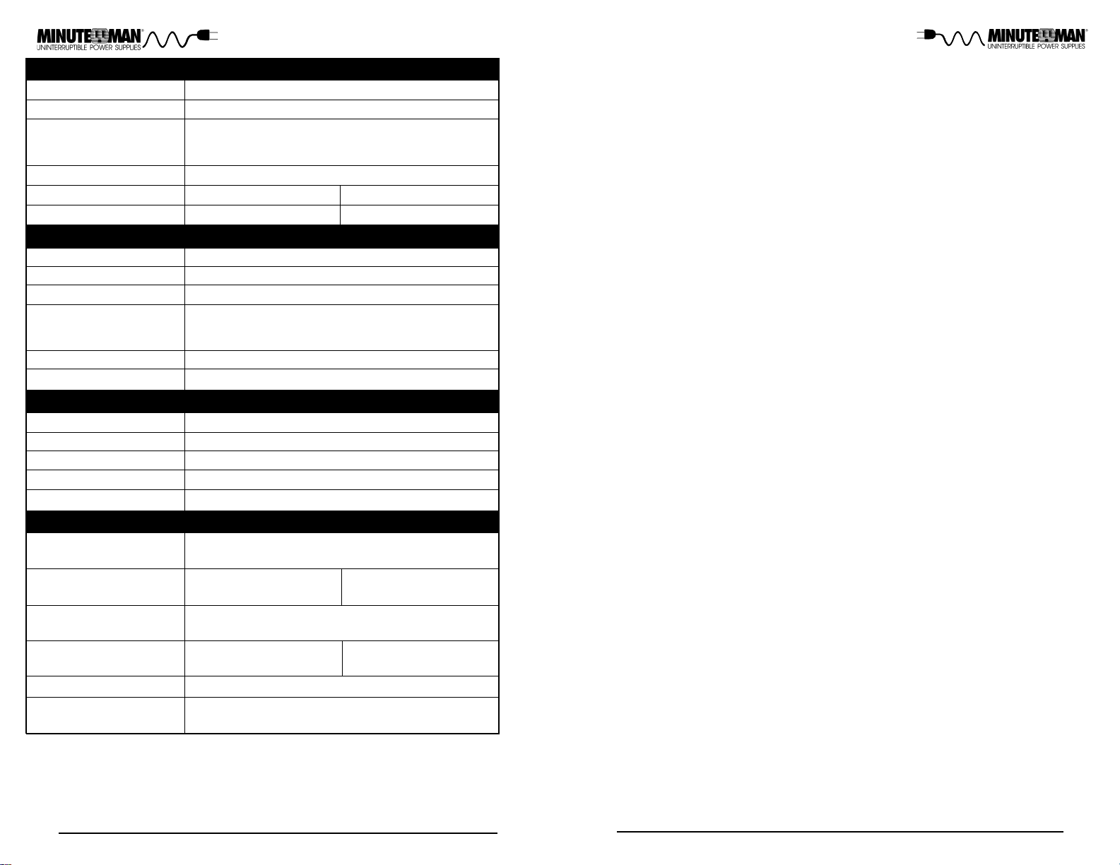
Chapter 8: Specifications
SYSTEM SPECIFICA TIONS
11.Verify proper polarity . Connect the battery negative (Black) wire to the battery
negative (Black) terminal on the new battery module.
NOTE: Some sparking might occur this is normal.
12.Slide the new battery module into the UPS.
13.Reinstall the battery door on the UPS.
14.Properly dispose of the old battery module at an appropriate recycling facility or return them to the supplier in the packing material for the new battery module.
15.The UPS is now ready for the normal operation.
NOTE: If the UPS has a Weak/Bad Battery Alarm after replacing the battery
module, a battery test must be performed to clear the Weak/Bad Battery Alarm.
A battery test can be performed by using the software or by disconnecting the
power cord from the wall outlet for 10-seconds and then reconnecting the
power cord back to the wall outlet.
Model Number
T opology
Maximum Power Capacity
EN750LCD
Standby , Simulated Sine Wave
750V A
450W
EN900LCD
900VA
500W
INPUT
Number of Phase Single (1∅ 2W +G)
Nominal Voltage 120VAC
Acceptable Input voltage
Voltage Range
Frequency Limits
Low Voltage Transfer Point
High Voltage Transfer Point
Input Protection
95V resets to Utility Power at 99V or higher
140V resets to Utility Power at 136V or lower
0 - 150VAC
95 - 140VAC
60 Hz, +/-6Hz
Resettable Circuit Breaker
OUTPUT NON-BA TTERY OPERA TION
Voltage Range
Voltage Regulation 120V AC: -20.8% - +16.7%
Frequency Range 60Hz: 54 - 66Hz
Efficiency (Line Mode)
95 - 140VAC
>95% (Full Load)
OUTPUT BA TTERY OPERA TION
Waveform T ype
Nominal Voltage
Voltage Regulation +/-5% (until Low Battery Warning)
Frequency
Transfer Time
Overload Capacity
Protection
60Hz, +/-0.5Hz (unless synchronized to utility)
AC Mode: 105% for 1-minute then shutdown, 115% Shutdown Immediately
DC Mode: 105% for 20-seconds then shutdown, 115% Shutdown Immediately
Over-Current, Short-Circuit Protected and Latching Shutdown
Simulated Sine Wave
120VAC
6 ms Typical
REGULA TORY COMPLIANCE
Safety and Approvals
cTUVus (Conforms to UL1778 5th Edition & CSA 22.2 no. 107.314 / R: 2014), FCC Class B, CE certified, Energy Star certified,
RoHS2 (EU Directive 2011/65/EU)
20
21
Page 13
BA TTERY SYSTEM
Battery Type
Typical Recharge T ime
Typical Battery Life
Battery Module Part # BM0068
Runtime: Full Load (minutes)
Runtime: Half Load (minutes)
Sealed, Non-Spillable, Maintenance Free, V alue Regulated Lead Acid
8-hours to 90% capacity from a full load discharge
3 to 5 years. Environmental factors do affect battery life. High
temperatures, poor utility power, and frequent, short duration
discharges have a negative impact on battery life.
3
11
SURGE PROTECTION AND FIL TERING
Surge Energy Rating 500 J
Surge Current Capability
Surge Response Time
Surge voltage let-through (as a
percentage of an applied ANSI
C62.41 Cat. A +/-6 kV)
Noise Filter
Audible Noise at 1 m (3 ft.)
10000 Amps total (one time 8 to 20us waveform)
0 ns (instantaneous) normal mode; <5 ns common mode
< 14%
>45db normal and common mode EMI/RFI suppression
<45 dBA
ENVIRONMENT AL
Operating T emperature
Operating Elevation
Operating/Storage Humidity
Storage T emperature
Storage Elevation
0 to 40°C (+32 to +104°F)
0 to 3000m (0 to +10,000 ft)
0 - 95% Non-Condensing
-15 to +45°C (+5 to +113°F)
0 to 15,000m (0 to +50,000 ft)
PHYSICAL
Size - Net
L X W X H
Weight - Net
Size - Shipping
L X W X H
Weight - Shipping
Power Cord
Output Receptacles
7.7 lbs
3.5 Kgs
8.4 lbs
3.8 Kgs
5 - NEMA 5-15R Battery Backup & Surge
5 - NEMA 5-15R Surge Only
12.6 x 7.2 x 3.6"
320 x 183 x 92 mm
15.0 x 5.6 x 10.4"
382 x 143 x 263 mm
NEMA 5-15P W/6 ft cord
3
11
8.4 lbs
3.8 Kgs
9.0 lbs
4.1 Kgs
Chapter 9: Limited Product Warranty
Para Systems, Inc. (Para Systems) warrants this equipment, when properly applied and
operated within specified conditions, against faulty materials (excluding the batteries) or
workmanship for a period of three years from the date of purchase. Para Systems Inc.
(Para Systems) warrants the batteries for a period of two years from the date of purchase. For equipment sites within the United States and Canada, this warranty covers
depot repair or replacement of defective equipment at the discretion of Para Systems.
Depot repair will be from the nearest authorized service center. The customer pays for
shipping the product to Para Systems. Para Systems pays ground freight to ship the
product back to the customer. Replacement p arts and warranty labor will be borne by
Para Systems. For equipment located outside of the United St ates and Canada, Para
Systems only covers faulty parts. Para Systems products that are depot repaired or
replaced pursuant to this warranty shall only be warranted for the unexpired portion of
the warranty applying to the original product. This warranty applies only to the original
purchaser who must have properly registered the product within 10 days of purchase.
The warranty shall be void if (a) the equipment is damaged by the customer, is improperly used, is subjected to an adverse operating environment, or is operated outside the
limits of its electrical specifications; (b) the equipment is repaired or modified by anyone
other than Para Systems or Para Systems approved personnel; or (c) has been used in
a manner contrary to the product’s User's Manual or other written instructions.
Any technical advice furnished before or after delivery in regard to use or application of
Para Systems’ equipment is furnished without charge and on the basis that it represents
Para Systems’ best judgment under the circumstances, but it is used at the recipient’s
sole risk.
EXCEPT AS PROVIDED HEREIN, PARA SYSTEMS MAKES NO W ARRANTIES, EXPRESSED OR IMPLIED, INCLUDING WARRANTIES OF MERCHANT ABILITY AND FITNESS FOR A P ARTICULAR PURPOSE. Some states do not permit limitation of implied
warranties; therefore, the aforesaid limitation(s) may not apply to the purchaser .
EXCEPT AS PROVIDED ABOVE, IN NO EVENT WILL PARA SYSTEMS BE LIABLE
FOR DIRECT , INDIRECT , SPECIAL, INCIDENT AL, OR CONSEQUENTIAL DAMAGES
ARISING OUT OF THE USE OF THIS PRODUCT, EVEN IF ADVISED OF THE POSSIBILITY OF SUCH DAMAGE. Specifically , Para Systems is not liable for any costs, such
as; labor for on-site installation, on-site maintenance or on-site service, lost profits or
revenue, loss of equipment, loss of use of equipment, loss of software, loss of data, cost
of substitutes, claims by third parties, or otherwise. The sole and exclusive remedy for
breach of any warranty , expressed or implied, concerning Para Systems’ products and
the only obligation of Para Systems hereunder, shall be depot rep air or replacement of
defective equipment, components, or parts; or, at Para Systems’ option, refund of the
purchase price or substitution with an equivalent replacement product. This warranty
gives you specific legal rights and you may also have other rights which vary from state
to state.
22
No employee, salesman, or agent of Para Systems is authorized to add to or vary the
terms of this warranty .
23
Page 14

A1. DECLARATION OF CONFORMITY
Application of Council Directive(s): 2004/108/EC, 2006/95/EC, cTUVus (for
UL1778)
St andard(s) to which Conformity is declared: EN61000-3-2, EN61000-3-3,
EN62040-2, IEC61000-2-2 IEC61000-4-2, IEC61000-4-3, IEC61000-4-4,
IEC61000-4-5, IEC61000-4-6, IEC61000-4-8, IEEE C62.41 Category A1,
UL1778, CSA 22.2 no. 107.3-14 / R: 2014, FCC Class B
Manufacturer’s Name: Para Systems, Inc. (MINUTEMAN UPS)
Manufacturer’s Address: 1455 LeMay Drive
Carrollton, Texas 75007 USA
Type of Equipment: Uninterruptible Power Supplies (UPS)
Model No: EN750LCD, EN900LCD
Y ear of Manufacture: Beginning September, 2016
Notes:
I hereby declare that the equipment specified above conforms to the above
Directive(s).
Robert Calhoun
(Name)
Place: Carrollton, Texas, USA
24
Manager Engineering
(Position)
Date: September 1, 2016
25
 Loading...