

Page 1

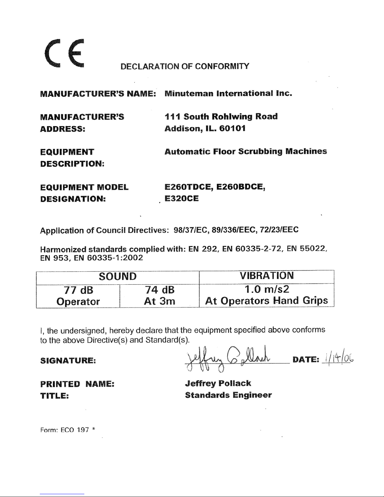
ES320
Floor Scrubber
Traction Driven
Model #:
E320QP
E320CE
E320QPIW
OPERATION
■ SERVICE ■ PARTS ■ CARE
Page 2
Page 3

TABLE OF CONTENTS
IMPORTANT SAFETY INSTRUCTIONS...........................................................................................................................................1
FOR SAFETY DURING OPERATION:..................................................................................................................... .........................1
FOR SAFETY WHEN SERVICING OR MAINTAINING MACHINE:..............................................................................................1
ELECTRICAL REQUIREMENTS.......................................................................................................................................................2
BATTERY REQUIREMENTS.............................................................................................................................................................2
BATTERY SERVICE AND INSTALLATION....................................................................................................................................2
BATTERY INSTALLATION:.............................................................................................................................................................2
CHARGING BATTERIES:..................................................................................................................................................................2
CONTROL PANEL IDENTIFICATION..............................................................................................................................................3
OPERATING INSTRUCTIONS............................................................................................................................................................4
MAINTENANCE.....................................................................................................................................................................................4
REAR SQUEEGEE.................................................................................................................................................................................5
REAR SQUEEGEE COMPONENTS...................................................................................................................................................5
REAR SQUEEGEE ADJUSTMENT....................................................................................................................................................6
EXPLODED VIEWS...............................................................................................................................................................................7
MAIN ASSEMBLY..............................................................................................................................................................................7
MAIN ASSEMBLY BOM....................................................................................................................................................................8
SOLUTION & RECOVERY TANK.....................................................................................................................................................9
SOLUTION & RECOVERY TANK BOM.........................................................................................................................................10
MAINFRAME ASSEMBLY ..............................................................................................................................................................11
MAINFRAME ASSEMBLY BOM ....................................................................................................................................................12
LINKAGE ASSEMBLY.....................................................................................................................................................................13
LINKAGE ASSEMBLY BOM...........................................................................................................................................................14
CONTROL PANELS..........................................................................................................................................................................15
CONTROL PANELS BOM................................................................................................................................................................16
SQUEEGEE LIFT MECHANISM ASSEMBLY................................................................................................................................17
SQUEEGEE LIFT MECHANISM ASSEMBLY BOM......................................................................................................................18
SQUEEGEE ADJUSTMENT MECHANISM ASSEMBLY..............................................................................................................19
SQUEEGEE BLADE ASSEMBLY....................................................................................................................................................20
WIRING DIAGRAM (STANDARD MODELS).................................................................................................................................21
WIRING DIAGRAM (CE MODELS).................................................................................................................................................23
MINUTEMAN INTERNATIONAL MADE SIMPLE COMMER CI AL LIMITED WARRANTY..............................................25
Page 4

IMPORTANT SAFETY INSTRUCTIONS
Operators must read and understand this manual before operating or maintaining this machine.
Do not operate this machine in areas containing flammable or explosive materials.
This machine is designed solely for scrubbing dirt and dust in an indoor environ m ent. Minuteman does not
recommend using this machine in any other capacity.
The following information below may cause a potential hazard to the operator and equipment. Read this manual
carefully and be aware when these conditions can exist. Take necessary steps to locate all safety devices on the
machine and train the personnel operating the machine. Report any machine damage or faulty operation
immediately. Do not use machine if it is not in proper operating condition.
FOR SAFETY DURING OPERATION:
Keep hands and feet clear of moving parts while machine is in operation.
Make sure all safety devices are in place and operate properly. All covers, doors and latches must be closed and
fastened before use.
During operation, attention should be paid to other persons in the work area.
Electric motors and components can cause an explosion when operated near explosive materials or vapor. Do not
operate this machine near flammable materials such as solvents, thinners, fuels, grain dust, etc.
Store or park this machine on a level surface only, with the key switch in the off position. To prevent unauthorized
use, machine should be stored with the key removed.
This machine is designed for level operation only. Do not operate on ramps or inclines.
This machine is not suitable for picking up hazardous dusts.
Use caution when moving this machine into areas that are below freezing temperatures. Any water in the tanks or
hoses can cause damage to the machine.
FOR SAFETY WHEN SERVICING OR MAINTAINING MACHINE:
Stop on a level surface and turn off the machine.
Disconnect the power to the machine by unplugging the large, red terminal below the recovery tank whe n charging
batteries or during installation or removal of brushes.
Avoid moving parts. Do not wear loose jackets, shirts, or sleeves when working on machine.
Avoid contact with battery acid. Battery acid can cause burns. When working on or around batteries, wear protective
clothing and safety glasses. Remove metal jewelry. Do not lay tools or metal objects on top of batteries.
Charging batteries generates explosive gasses. Do not charge batteries when open flames or sparks are
present. Do not smoke. Make sure the charger is turned off before disconne cting it from the machine. Charge the
batteries in a well-ventilated area with the battery cover removed completely.
Do not clean machine with a pressure washer.
Authorized personnel must perform repairs and maintenance. Use ONLY Minuteman supplied repla ce m ent parts.
SAVE THESE INSTRUCTIONS
1
Page 5
ELECTRICAL REQUIREMENTS:
This piece of equipment operates on 24 VOLT DC.
BATTERY REQUIREMENTS:
4 x 6V, 275Ah batteries (Part Number 956740)
BATTERY SERVICE AND INSTALLATION
WARNING: Battery acid can cause burns. When working on or around batteries, wear protective
clothing and safety glasses. Remove metal jewelry. Do not lay tools or metal objects on top of
batteries.
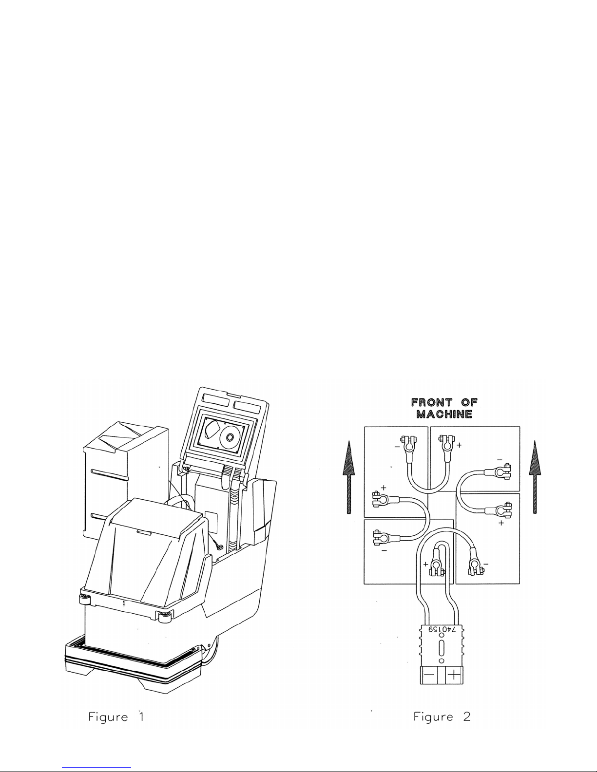
BATTERY INSTALLATION:
1. Disconnect tank drain hose from rear of machine.
2. Raise the tank assembly by raising rear cover and tilting tank, Figure 1.
3. Install batteries as shown in Figure 2.
CHARGING BATTERIES
Charging of batteries generates explosive gases. DO NOT CHARGE BATTERIES WHEN OPEN
FLAMES OR SPARKS ARE PRESENT. DO NOT SMOKE. Make sure charger is turned off before
disconnecting it from the batteries. Charge the batteries in well-ventilated area. Fluid levels should
be checked before and after charging and maintained at the proper levels.
:
2
Page 6
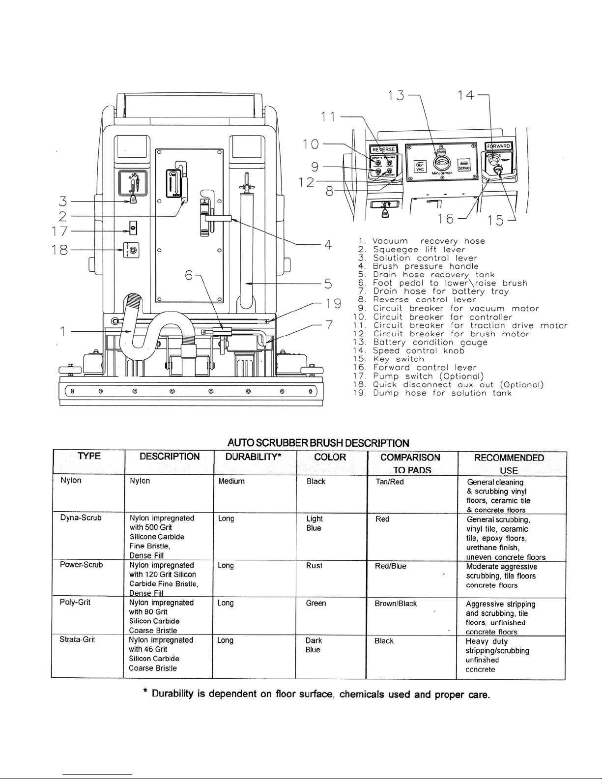
CONTROL PANEL IDENTIFICATION
3
Page 7

OPERATING INSTRUCTIONS
1. Filling: Fill the solution tank with the desired amount of water and add liquid cleaning solution
to the proper dilution ratio. DO NOT USE powdered cleaning chemicals. Powders are unlikely
to dissolve thoroughly, resulting in clogging the in-line solution filter. This can reduce or stop
water flow to the brush.
2. Close lid.
3. Turn on main power key switch (refer to page 5, #15).
4. Adjust main speed control knob (#14) to full counter-clockwise position.
5. Lower brush assembly:
• Depress foot pedal (#6) slightly and push in on lever (#4) to release. To increase brush
pressure, pull up and back on lever (#4) to lock position.
• To lift the brush, press the pedal down until lift mechanism engages.
• Brushes will begin to rotate when forward (#16) or reverse (#8) levers are engaged.
6. Adjust solution control feed lever (#3).
8. Lower squeegee assembly with lever (#2). This will turn on the vacuum motor. The vacuum will
remain on until the squeegee lever (#2) is raised. After this, the motor will continue to run for
an additional 10 seconds to clear the recovery lines.
Turning off the power using the key switch will immediately shut down all systems,
including vacuum motor, transaxle, and solution feed.
9. Squeeze forward handle (#16), and adjust forward speed using control knob (#14).
After Use:
1. Raise brushes with foot pedal (#6), brushes and solution flow will turn off .
2. Raise squeegee assembly; vacuum will shut off 10 seconds after raising.
3. Solution and recovery tanks should be emptied after every use. These tanks can be
emptied using drain hoses (#5 & #19).
MAINTENANCE
Daily:
1. Clean float assembly & squeegee blades.
2. Recharge batteries (check battery acid levels before and after charging).
Monthly:
1. Check wear on squeegee blades.
2. Grease front and rear wheels.
3. Grease pivot points on the brush motor assembly.
Every 500 hours check the condition of carbon brushes on vacuum motor and brush drive motor.
4
Page 8
REAR SQUEEGEE
The rear squeegee is the main element that acts as the conduit that transfers the spent
solution into the recovery tank. A daily maintenance check of this component is essential to
have optimum machine performance. The rear squeegee assembly is equipped with a
universal front blade that allows the operator the option to use a slotted and a non-slotted side
for specific applications. Each blade configuration has two usable edges. The rear blade
however has four usable edges.
The squeegee is pre-adjusted at the factory. Adjustments may be required to get
optimum performance for different floors and conditions.
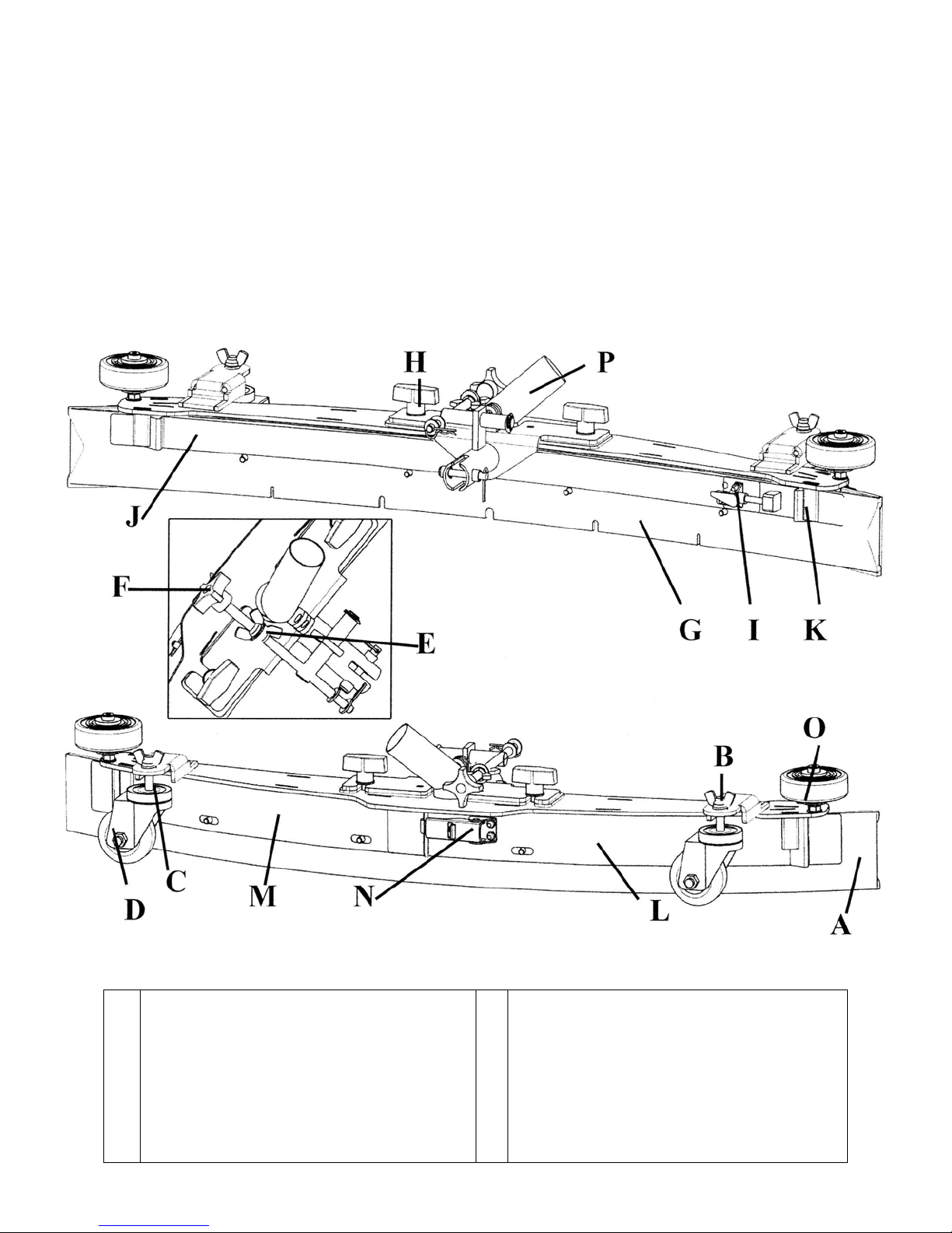
REAR SQUEEGEE COMPONENTS
A
Rear Squeegee Blade
B
Wing Nut (2)
C
Caster Stem (2)
D
Swivel Caster (2)
E
Wing Jam Nut (2)
F
Turnbuckle Adjustment Knob
G
Front Squeegee Blade
H
Wing Bolt (2)
I
Toggle Clamp
J
Front Strap (Long)
K
Front Strap (Short)
L
Rear Strap (Latch Side)
M
Rear Strap (Catch Side)
N
Latch
O
Guide Wheel (2)
P
Recovery Hose Intake
5
Page 9

REAR SQUEEGEE ADJUSTMENT
1. Ensure that the scrubber is on a relatively flat surface. Turn on the key switch and lower the
squeegee to the floor using the squeegee lift lever. This turns the vacuum motor on.
2. Move the scrubber one or two feet forward slowly while someone behind the machine checks
the rear squeegee blade (item A) for uniform deflection to the floor.
3. If uneven deflection or lay is evident, minor adjustments may be necessary to avoid streaking
and uneven wear on the blade.
4. To correct this, loosen the wing jam nut (item B) in order to adjust the caster height. If the
squeegee blade is deflecting too much, the casters (item D) need to be lowered to control the
down pressure. Lower the caster by turning the exposed threaded stem (item C) on the
caster clockwise. Make the adjustment a few turns at a time. Repeat step 2.
5. If the blades are not deflecting enough, raise the caster by turning the stem counterclockwise to adjust the caster height to allow more down pressure on the squeegee. Repeat
step 2.
6. Make sure there is even deflection on the entire length of the rear blade. Adjust the casters
and retighten the wing jam nuts to lock the caster setting in place.
7. Pitch adjustment is necessary if the outer ends on the squeegee blade do not contact the
floor and there is too much deflection in the middle area or if the outer ends are over
deflected and there is no contact in the middle.
8. To adjust the pitch, Repeat step 2.
9. Loosen the two wing jam nuts (item E) that lock the pitch angle. Turning the knob (item F)
clockwise or counter-clockwise controls the forward and backward pitch of the squeegee.
Having the rear blades deflected uniformly along its entire length is the desired set-up.
10. Repeat step 2 until desired set-up is achieved.
11. In certain applications where a non-slotted front wiper blade (item G) is needed, detach the
rear squeegee assembly by loosening the two wing bolts (item H). Unlock the toggle clamp
(item I) on the front squeegee to release the front long strap (item J) and slide the front short
strap (item K). Flip the blade over to the non-slotted side. Reattach the straps and lock the
clamp back in place.
12. You can also easily replace the rear blade by unlatching the latch (item N) and removing the
two rear straps (items L & M) by sliding them off the assembly. You can then flip the blade
over in order to use a new edge for better wiping action.
6
Page 10

EXPLODED VIEWS
7
MAIN ASSEMBLY
Page 11

MAIN ASSEMBLY BOM
8
ITEM PART NO. REQ'D DESCRIPTION
1 260087 2 HINGE-15"
2 260090 1 REAR BASE CHAR GREY
3 260091B 1 RECOVERY TANK, ES260320 BURGUNDY
4 260092B 1 SOLUTION TANK, ES260320 BURGUNDY
5 260360 1 MAINFRAME MMAN 260 TD
6 260096B 1 LID RECOVERY 260 BURGUNDY
7 260620 1 SKIRT, BRUSH, ES320
8 260662 1 BKT, SKIRT RETAINER RH, ES320
9 260662-1 1 BKT, SKIRT RETAINER LH, ES320
10 260635 1 DECK TOP ASSY, ES320
11 260149 1 U CHANNEL 12"
12 260157 2 LID GSKT SHORT 260B
13 260158 2 LID GSKT 260B
14 260159 1 HOSE-VAC 1.5 X 78" WIRELOC
15 260160 1 RECOVER HOSE ASY260B
16 260169 1 LID FLAP
17 260170 2 RETAINER STRIP
18 260203 2 CLAMP-HOSE 102120 MURRAY
19 260212 1 SCREEN FILTER
20 260294 1 GASKET 260
21 260299 1 SHUT OFF PLATE ASY
22 260301 1 DEFLECTOR FLAP
23 260664 2 REC LID MOUNT WMT, ES260320
24 450037 1 ADAPTER MCH
25 450081 1 WSR 1.908 X 2.41 X .03 SS
26 711425 11 NUT-FLANGED WIZZ 1/4-20 STL ZP
27 712534 9 SCR-MC 10-24 X .50 SS
28 712536 3 SCR-MC 10-24 X .62 SS
29 711161 10 SCR-HI/LO #10 X 3/4 ZINC
30 711505 4 WSR-FLT 1/4
31 712540 12 SCR-MC 10-24 X .37 SS TH
32 712565 17 SCR-MC 1/4-20 X .62 SS
33 712667 4 NUT-HEX NYLOC 1/4-20 SS
34 715607 1 DECAL-BATTERY CABLE ROUT
35 760263 2 FOAM TAPE 1/16 X 1/2
36 828970 1 WSR NEOP 1.87X2.4X.125
37 828971 1 NUT 1 1/2 PIPE THREAD
38 715841 1 DECAL, ES260320
Page 12

SOLUTION AND RECOVERY TANK
9
Page 13

E
SOLUTION & RECOVERY TANK BOM
10
ITEM PART NO. REQ'D DESCRIPTION
1 130118 1 STRAINER-SOLUTION M3-40
2 210045 1 CABLE-SOLUTION CONTROL
3 210370 1 SOLUTION VALVE BRACKET
4 210408 1 FITTING BRASS TEE 3/8MPT&FPT
5 210409 1 FITTING BRASS 3/8MPT 3/8FPT
6 210410 1 FITTING BRASS 3/8FPT 3/8HOSE
7 210414 1 O RING 2-113
8 260029B 1 LID SOLUTION BURGUNDY
9 260091B 1 RECOVERY TANK, ES260320 BURGUNDY
10 260092B 1 SOLUTION TANK, ES260320 BURGUNDY
11 260156 1 FLOAT ASSEMBLY
12 260670 1 TUBING, PLASTIC 3/8 ID X 70"
13 260178 3 FITTING NYLON T 3/8HOSE
14 260179 4 HOSE-NYLOBRAID 3/8 X 2.38
15 260182 1 SOLUTION HOSE C/L 18"
16 260184 1 SUPPORT ANGLE
17 260202 1 HOSE ASY 260B NEW STYLE
18 260203 1 CLAMP-HOSE 102120 MURRAY
19 260214 2 TANK CABLE ASY 260
20 260669 1 BRACKET, SOLENOID ES320
21 281637 2 HOSE-WIRE REINF 3/8 X 11"
22 320269 1 STRAP, DRAIN PLUG RETAINING
23 342430 1 FITTING BRASS 3/8MPT 3/8HOSE
24 430114 1 FITTING NYLON CAP 1/4FPT
25 450021 1 HINGE
26 450040 2 ELBOW PLT 3/8MPTX3/8BARB
27 450055 1 HOSE NYLO 3/8ID X 9"
28 450076 12 CLAMP-CRIMP 185R SS
29 450081 1 WSR 1.908 X 2.41 X .03 SS
30 710353 2 SCR-MC 10-32 X .37 ZINC
31 710985 2 SC 3/8-16 X .62
32 711124 1 SCR-ST-B 10 X .37 NI
33 711506 2 WSR-FLT 5/16 (NARROW) ST PL
34 711512 1 WSR-FLT .75 X 1.37 X .08
35 711513 1 WSR-FLT .689 X 1.06 X .029 SS
36 711553 2 WSR-INT LOCK #10
37 712041 2 BLT-SHOULDER 1/4-20 X .44 X .3
38 712540 7 SCR-MC 10-24 X .37 SS TH
39 712560 4 SCR-MC 1/4-20 X .50 SS NYL
40 712563 4 SCR-MC 1/4-20 X 1.00 SS
41 712667 4 NUT-HEX NYLOC 1/4-20 SS
42 740482 1 DIODE ASY
43 740493 1 WATER VALVE 24VDC
44 760220MCH 1 1.5 ADAPTER MCH
45 809413MCH 1 SOLUTION VALVE
46 828490 2 CLAMP-CRIMP 140R
47 828952 1 FITTING PP 1/4MPT 3/8BARB
48 828970 2 WSR NEOP 1.87X2.4X.125
49 828971 1 NUT 1 1/2 PIPE THREAD
50 828975 1 WSR NEOP .75X1.5X.09
51 829463 1 S S WASHER
52 830062 1 FITTING BRASS 90 3/8MPT 3/8FPT
53 832896 2 GUIDE WHEEL
54 832949 2 BRACKET BUMPER
55 833254 2 BUMPER WHEEL AXLE
56 833316 1 DRAIN PLUG
57 833325 1 FITTING NYLON 90 1/4MPT X 3/8HOS
Page 14

MAINFRAME ASSEMBLY
11
Page 15

MAINFRAME ASSEMBLY BOM
12
PARTS LIST
ITEM PART NO. REQ'D DESCRIPTION
1 210142 1 PEDAL PAD
2 260030 5 BUSHING-.5015 X .628 X .375 OI
3 260041 2 BUSHING-FLG .502 X .750 X .375
4 260043 1 LIFT ARM, LEFT SIDE
5 260046 1 PEDAL BRACE
6 260044 1 LIFT ARM, RIGHT SIDE
7 260054 1 PEDAL WELDMENT
8 260055PTD 1 LIFT HANDLE WELDMENT
9 260075 1 YOKE WELDMENT
10 260125 1 BUSHING-YOKE .407 X 1.687 STL
11 260128 1 SPACER-YOKE
12 260141 1 SPACER-LIFT ARM
13 260256 1 BASE 260TD CHAR GREY
14 260660 1 SQUEEGEE LIFT ASSY, ES260320
15 260360 1 MAINFRAME MMAN 260 TD
16 260366 2 TRANSAXLE BRACKET 260TD
17 260370 2 WHEEL 10 X 2.75 X.75 BORE
18 260371 2 KEY 3/16 X 3/16 X 2.00
19 710196 4 SCR-MC 5/16-18 X .62
20 710986 2 SC 3/8-16 X 1 ZINC
21 710992 1 BLT-SHOULDER 1/2 X 1.25 X 3/8
22 711228 8 BLT-HH 5/16-18 X .75 STL ZINC
23 711232 4 BLT-HH 5/16-18 X 1.50
24 711250 2 BLT-HH 3/8-16 X 1.25 STL ZINC
25 711374 2 NUT-NYLOC 5/16-18
26 711375 2 NUT-NYLOC 3/8-16 1/2NUT
27 711380 2 NUT-NYLOC 3/8-16
28 711439 3 NUT-FLANGED WIZZ 3/8-16
29 711507 2 WSR-FLT .37 X 1.12 X .06
30 711512 2 WSR-FLT .75 X 1.37 X .08
31 711545 16 WSR-HELICAL 5/16
32 711546 10 WSR-HELICAL 3/8
33 711575 22 WSR-FLT .31 X .75 X .06 STL
34 711579 2 WSR-FLT .56 X 1.00
35 712081 2 BLT-SHOULDER 5/16-18 X .75 X .
36 712099PLT 2 BLT-SHOULDER 1/2 X 1/2
37 712310 6 WSR-FLT .52 X .87 X .06 PL
38 712680 4 NUT-HEX 5/16-18 SS
39 713042 4 BLT-HH 3/8-16 X 1.00 #5
40 713045 1 BLT-HH 3/8-16 X 1.75 #5
41 713048 1 BLT-HH 3/8-16 X 2.50 #5
42 744160 1 TRANSAXLE-13" 24V
43 762340 2 BUSHING-.502 X .625 X .270 STL
44 809226 2 WSR-FLT .40 X 1.50 X .12
45 809247 2 SPACER-.442 X .50 X .312
46 827110 2 CASTER 5 INCH
47 832829 2 NUT-U TYPE 5/16 X 18
48 710493 2 SCR-MC 4-40 X .75 PAN HD
49 711596 2 WSR-INT LOCK #4
50 711428 2 NUT-HEX 4-40
51 747603-1 1 SWITCH, MICRO 1.34" ROLLER ARM
Page 16

LINKAGE ASSEMBLY
13
Page 17

LINKAGE ASSEMBLY BOM
14
1 833638 2 BRASS STUD 31 364-816 1 NUT-NYLOC 1/2-13 HALF
2A 430108 2 PAD DRVR-17B/E 32B 32 380064 1 RING, FOAM
2B 430034 2 BRUSH-17B/E 32B NYL 33 3312402 2 HUB-SCRUB BRUSH DRIVE
ITEM PART NO. REQ'D DESCRIPTION ITEM PART NO. REQ'D DESCRIPTION
2C 430137 2 BRUSH-SCRUB DYNA 170,32B 34 450038-H 2 Z BKT 5.7 VDE ZINC
2F 430132 2 BRUSH-STRATAGRIT 17B/B32 38 710823 2 SC 1/4-20 X .50 NYL
2E 430111 2 BRUSH-POLY GRIT 17B/E 32 37 710129 2 SCR-MC 8-32 X .50 ZINC
2D 430144 2 BRUSH-SCRUB POWER 170,32 36 710180 2 SCR-MC 1/4-20 X .75 ZINC
3 260009 1 BATTERY TRAY 14GA 39 710986 8 SC 3/8-16 X 1 ZINC
4 260030 4 BUSHING-.5015 X .628 X .375 OI 40 711160 3 SCR-HI/LO #10 X 5/8 ZINC
5 260036 8 PIN, RETAINER 41 711228 2 BLT-HH 5/16-18 X .75 STL ZINC
6 260640 1 MOTOR MOUNT WMT, RIGHT, ES320 42 711334 2 NUT-HEX 1/2-13 ST PL
7 260641 1 MOTOR MOUNT WMT, LEFT, ES320 43 711368 2 NUT-WING NYLOC 1/4-20 PL
8 260041 8 BUSHING-FLG .502 X .750 X .375 44 711425 8 NUT-FLANGED WIZZ 1/4-20
9 260049 4 LINKAGE BAR .312GA 45 711510 2 WSR-FLT .50 X 1.37 X .10
10 46 711517 2 WSR-FLT .77 X 1.37 X .03
11 260068 1 SPACER-SPRG 47 711545 2 WSR-HELICAL 5/16
12 260673 2 DECK COVER SIDE SUPPORT WMT 48 711713 10 RET RING-E EXT .50
13 260645 1 MOTOR FRAME WMT, ES320 49 712310 20 WSR-FLT .52 X .87 X .06 PL
14 260137 1 SPRING-COMP .960 X 2.00 ZINC 50 712667 1 NUT-HEX NYLOC 1/4-20 SS
15 260150 1 BATTERY LINER 51 740132 2 INSULATOR (GLASTIC)
16 260159 1 HOSE-VAC 1.5 X 78" WIRELOC 52 740159 1 CIRCUIT BRKR-175 RED HOUSING
17 210466 1 CABLE CONDUIT 53 740209 2 GEARMOTOR 24V 17B
18 260667 2 DECK COVER MOUNT BKT WITH PIN 54 740225 1 VAC MTR 6515-13 24V
20 260203 1 CLAMP-HOSE 102120 MURRAY 55 762073 1 BUSHING-.259 X .375 X .265
21 260214 2 TNK CABLE ASY 260 56 809444 1 CLIP-CORD
22 260224 1 DRAIN HOSE 1/4 X 18 SILICONE 57 828264 1 WASHER CUP
24 260315 1 LIFT CABLE BRACKET 58 828490 1 CLAMP-CRIMP 140R
25 260337 1 CABLE-SQUEEGEE 59 829067 2 CLAMP-CRIMP 560R
26 290017 1 MOLDED VAC MOTOR GASKET 60 832996 1 TERMINAL BLOCK 2POLE VDE
27 320248 2 PIN-CLEVIS, SLOTTED 61 833191 1 HOSE RUBBER FLEX 2X9
28 320271 1 FITTING PP 90 3/8MPT 3/8HOSE 62 833265PLT 1 THREADED SPACER PLT ZINC
29 320272 2 NOZZLE BODY LOCKNUT 63 840011 1 VAC MOTOR COVER TOP
30 320273 1 CLAMP-HOSE SHUT-OFF 64 840012 1 VAC MOTOR COVER BOTTOM
Page 18

CONTROL PANELS
15
Page 19

CONTROL PANEL BOM
16
PARTS LIST
1 200340 2 SPACER-SCR BOARD 41 712100 2 BLT-SHOULDER 3/8 X 2.25
2 210045 1 CABLE-SOLUTION CONTROL 42 712320 2 WSR .22 X .45 X .04 NYL
3 260066 4 BUSHING-FLG .377 X .687 X .406 43 712540 6 SCR-MC 10-24 X .37 SS TH
4 260069MCH 1 LEFT HANDLE MACHINED 44 712570 2 SCR-MC 1/4-20 X 1.75 SS
5 260070MCH 1 RIGHT HANDLE MACHINED 45 712814 1 SCR-MC 10-24 X .87 ZINC
ITEM PART NO. REQ'D DESCRIPTION ITEM PART NO. REQ'D DESCRIPTION
6 260099 1 CONTROL LEVER MOUNTING BRACKET 46 712822 8 SCR-MC TR HD 10-24 X .50 SS
7 260084 1 DASHBOARD 47 715602-1 1 DECAL, REVERSE ES260320
8 260198 1 SWITCH BRACKET 260TD 48 715603 1 DECAL-SQUEEGEE LIFT 260
9 260210 1 MOISTURE GUARD SCR 260TD 49 715604 1 DECAL-SOLUTION 260
10 260253 1 ELECTRICAL PANEL 50 715605 1 DECAL-BRUSH POSITION
11 260254 1 SWITCH ACTUATOR 260TD 51 715608CE 1 DECAL-FORWARD TD CE
12 260255 1 SPEED CONTROL BRACKET 260TD 52 740238 1 CIRCUIT BREAKER-18AMP PUSH BUTTON
13 260658 1 BKT, CIRCUIT BREAKER PANEL, ES320 53 740132 2 INSULATOR (GLASTIC)
14 260284 1 REAR PANEL ASY 260TD 54 740247 1 CIRCUIT BREAKER-30AMP PUSH BUTTON
15 260286 1 SQUEEGEE HANDLE WELDMENT 55 740216 1 GUAGE BATTERY COND
16 260291 1 HANDLE GRIP 260TD 56 740241 2 CONTACT-24V 50AMP
17 260337 1 CABLE-SQUEEGEE 57 746006 1 CIRCUIT BRKR-3AMP PUSH BUTTON
18 260274 1 GROMMET Z-421 58 742266 1 CIRCUIT BREAKER-60AMP PUSH BUTTON
19 320248 2 CLEVIS, SLOTTED 59 740804 1 POTENTIOMETER ASSY.
20 281579 1 SCV SQUEEGEE BLADE ASSY 32" 60 740944-1 1 SPD CONT 24V 1203A225
21 430051 2 SPRING-RETURN .313 X .438 X 2. 61 747024 1 KEY SWITCH, SPST SOLDER LEADS
22 710178 4 SCR-MC TR HD 1/4-20 X .50 ZINC 62 741640 1 RELAY-TRUE OFF 24V 10SEC
23 710180 15 SCR-MC 1/4-20 X .75 ZINC 63 760286 1 WIRE FORMED HOOK
24 711125 2 SCR-ST-B 10 X .50 NI 64 762400 1 BUSHING-HEYCO 1-5/8 X 2-1/8 X
25 711161 6 SCR-HI/LO #10 X 3/4 ZINC 65 788147 1 SOLENOID-24VDC
26 711368 2 NUT-WING NYLOC 1/4-20 PL 66 805637 1 SCR INSULATOR
27 711372 2 NUT-NYLOC 8-32 67 809311 2 PIN-COTTER 7/64 X 1
28 711373 1 NUT-NYLOC 1/4-20 68 809874 1 KNOB SPEED CONTROL
29 711420 2 NUT-HEX JAM 5/16-18 STPL 69 827060 1 SWITCH-DRIVE
30 711503 2 WSR-FLT #10 70 828935 2 SPACER
31 711505 4 WSR-FLT 1/4 71 832015 2 SPACER-.38 X .5 X .14
32 711506 2 WSR-FLT 5/16 (NARROW) ST PL 72 833102 1 SPRING-KNOB .60 X .73 X 1.75 Z
33 711523 4 WSR-WAVE .37 X .68 X .08 73 833374 2 PIN-HAIRPIN COTTER 3/8
34 711544 4 WSR-HELICAL 1/4 74 833638 2 BRASS STUD
35 711553 1 WSR-INT LOCK #10 75 881002 2 PIN-CLEVIS 11-083 ZINC
36 711575 1 WSR-FLT .31 X .75 X .06 STL 76 710493 2 SCR-MC 4-40 X .75 PAN HD
37 711668 2 PIN-CLEVIS 3/8 X 1 11-141 77 711596 2 WSR-INT LOCK #4
38 711671 1 PIN-CLEVIS .31 X 2.13 11-10 78 711428 2 NUT-HEX 4-40
39 711808 1 PIN-HAIRPIN COTTER #13 79 747603-1 1 SWITCH, MICRO 1.34" ROLLER ARM
40 712070 1 BLT-SHOULDER 5/16 X 3/4 X 1/4-
Page 20

SQUEEGEE LIFT MECHANISM ASSEMBLY (P.N. 260660)
17
Page 21

SQUEEGEE LIFT MECHANISM ASSEMBLY BOM
18
PARTS LIST
ITEM PART NO. REQ'D DESCRIPTION
1 210400 2 SPACER-TUBE
2 260041 2 BUSHING-FLG .502 X .627 X .375
3 260292 4 BLT-SWING ZINC PLATED
4 260314 1 WELD-HOUSING SPRING
5 260659-1 1 SQUEEGEE OKE SUB-ASSY ES260/320
6 260681 1 TORSION SPRING
7 320008 2 PIVOT BRACKET ASSEMBLY
8 430051 2 SPRING-RETURN .313 X .438 X 2.93 SS
9 710592 2 SCR-MC TH 1/4-20 X 3.00 SS
10 711425 4 NUT-FLANGED WIZZ 1/4-20 STL ZP
11 711517 2 WSR-FLT .77 X 1.37 X .03
12 711524 1 WSR-WAVE .52 X .87 X .01
13 711713 1 RET RING-E EXT .50
14 711715 2 RET RING-EXT .75
15 712098 1 PIN - CLEVIS 1/2 X 3.5
16 712665 2 NUT-HEX 1/4-20 SS
17 762004 1 PIN, ADJUSTING
18 833374 1 PIN - HAIRPIN COTTER 3/8
Page 22

SQUEEGEE ADJUSTMENT MECHANISM ASSEMBLY (P.N. 241730-1)
19
Page 23

SQUEEGEE BLADE ASSEMBLYP.N. 281579)
20
Page 24

21
Page 25

22
Page 26

23
Page 27

24
Page 28

Minuteman International Made Simple Commercial Limited Warranty
Minuteman International, Inc. warrants to the original purchaser/user that the product is free from defects in workmanship and materials
under normal use. Minuteman will, at its option, repair or replace without charge, parts that fail under normal use and service wh en
operated and maintained in accordance with the applicable operation and instructi on manuals. All warranty claims must be submit ted
through and approved by factory authorized repair stations.
This warranty does not apply to normal wear, or to items whose life is dependent on their use and care, such as belts, cords, s witches,
hoses, rubber parts, electrical motor components or adjustments. Parts not manufactured by Minuteman are covered by and subject to
the warranties and/or guarantees of their manufacturers. Please contact Minutem an for procedures in warranty claims against these
manufacturers.
Special warning to purchaser -- Use of replacement filters and/or prefilters not manufactured by Minuteman or its designated
licensees, will void all warranties expressed or implied. A potential he alth hazard exits without original equipment replacement.
All warranted items become the sole property of Minuteman or its original manufacturer, whichever the case may be.
Minuteman disclaims any implied warranty, including the warranty of merchantability and the warranty of fitness for a particular
purpose. Minuteman assumes no responsibility for any speci al, incidental or consequential damages.
This limited warranty is applicable only in the U.S.A. and Can ada, and is extended only to the original user/purchaser of this product.
Customers outside the U.S.A. and Canada should contact their local distributor for export warranty policies. Minuteman is not
responsible for costs or repairs performed by persons other than those specifically authorized by Minu teman. This warranty does not
apply to damage from transportation, alterations by unauthorized pers ons, misuse or abuse of the equipment, use of non-compatible
chemicals, or damage to property, or loss of income due to malfunctions of the product.
If a difficulty develops with this machine, you should contact the dealer from whom it was purchased.
This warranty gives you specific legal rights, and you may have other rights which vary from state to state. Some states do not allow the
exclusion or limitation of special, incidental or consequential damages, or limitations on how long an implied warranty lasts, so the
above exclusions and limitations may not apply to you.
Cord Electric Group………. Three years parts, t wo years labor, ni nety days travel (Not to exceed two hours)
Exceptions………. Port-A-Scrub, one year parts, six months labor
MPV 13, one year parts
MPV 14 and 18, two years parts, one year labor
RapidAir blower, one year parts, one year labor
Explosion-Proof Vacuum, one year parts, one year labor
Pneumatic Vacuums, three years parts, one year labor
Battery Operated Group….. Three years parts, two years labor, ninety days travel
(Not to exceed two hours)
Exceptions……Sweepers, one year parts, one year labor, ninety days travel
(Not to exceed two hours)
Internal Combustion Group….One year parts, one year labor, ninety day travel
(Not to exceed two hours)
Replacement Parts……………..Ninety days
Batteries………………………….0-3 months replacement, 4-12 months pro-rate
Polypropylene Plastic Tanks…Ten years, no additional labor
A Member of the Hako Group of Companies
111 South Rohlwing Road · Addison, Illinois 60101 USA 988030
Phone 630- 627-6900 · Fax 630- 627-1130 Rev B 10/06
E-Mail, www.minutemanintl.com Printed in USA
25
 Loading...