

Page 1

SERVICE MANUAL
For E Series Scrubbers
Models: E24, E26, E28,
E30, E33, E33XL
,
E30ECO, E2830, E3030,
For:
Training
E3330 and H26
Troubleshooting
Adjustments
Rev 07/07/2014
Page 2

Contents
1 Warnings Page 6
2 General Information Page 7
3 Maintenance Intervals Page 8
3.1 Minuteman System Maintenance K (Customer) Page 9
3.2 Minuteman System Maintenance I (125 hours
of o
p
eration) Page 10
p)
g
3.3 Minuteman System Maintenance II (250 hours
of operation) Page 11
3.4 Minuteman System Maintenance S (500 hrs of
operation, at least yearly)
Page 12
4 Squeegee Cable and Recovery Tank Gasket Page 13
4.1 Squeegee Adjustment (First Version) Page 14
4.2 Squeegee Adjustment (new Style) Page 15
4.3 Squeegee Lift Cable, Micro Switch, Vacuum Motor
Page 16
4.4 Squeegee Wheel Adjustment Page 17
5 Brush Head (Disk Brushes) Connections Page 18
5.1 Brush Motor Information Page 19
2
Page 3

Contents
6 Brush Head Transport Position Page 21
6.1 Brush Switch Page 22
6.2 B
rush Pressure
Adj
ustment on the Disk Models
P
age
23
6.3 Brush Pressure (Disk Decks) Page 24
6.4 Cylindrical Brush Head Electrical Connections Page 25
6.5 Cylindrical Brush Head Adjustment Page 26
7 Drive and Wheels - General Data Page 27
7.1 Electric Brake Page 27
7.2 Transaxle Motor Page 28
7.3 Carbon Brushes
Page 29
7.4 Drive Potentiometer Page 30
8 Water Supply Page 31
8.1 Solenoid Page 31
8.2 Solution Filter
Page 31
8.3 Solution Tank Cleanout Page 32
8.4 Solution Flow Rates Page 33
8.5 Water Pump Page 34
9 The Last E
rror
P
age
35
10 Table of Error Codes and Information Page 36
3
Page 4

Contents
11 Battery Charger Page 38
11.1 Operating Instructions Page 40
11.2 Charger Error Codes Page 40
11.3 Charger Trouble Shooting
Page 44
11.4 Charger Maintenance Points Page 45
11.5 Programming The Charger Page 46
11.6 Replacing The Charger Harness Page 49
12 Batteri
es
P
age
50
12.1 Maintaining Wet Lead Acid Batteries Page 50
12.2 Load Testing Batteries Page 52
12.3 Hydrometer Testing Page 53
13 Fuse Locations Version 2 Page 56
13.1 Controller Version 3 Page 57
4
Page 5

Contents
14 Controller Connections Page 58
15 Trouble Shooting Controller Page 59
16 Contactor Harness Page 60
g
17 Contactor Wiring Page 61
18
Testing the Main Power Relay Page 63
19 Wiring Diagram Models with 19 Gallon Tanks Page 68
20 Wiring Diagram Models with 24 Gallon Tanks Page
7220 Wiring Diagram Models with 24 Gallon Tanks Page 73
20 Wiring Diagram Models with 30 Gallon Tanks Page 7
8
21 Notes Page 83
5
Page 6

1. Warnings
• Disconnect the A.C. Cord from the outlet and and D.C. Cord from the battery
pack before servicing the machine
.
Except for making voltage and current
measurements.
• Before replacing the main fuses, only loosen the nuts. Do not remove them
completely. Failure to do so could cause a short circuit.
• Place the new stripe fuse fully and evenly under the nuts and washers and
make sure not to twist the end tabs, they can easily be torn.
• After an
y
repair work is done, test the machine for proper operation.
yp , pp p
• When servicing the machine always observe the general safety and accident
prevention guidlines.
6
Page 7

2. General Information
•The display offers a service indication. Upon turning on the key switch, a four digit
number describing the software version (e.g. 1.0.0.2) appears for about 3 seconds,
foll
owed by another 4-digit code indicating the last error recorded, then followed by
the hour meter.
•If a failure occurs, the code appears in the control panel and an acoustic signal
sounds. The current error code appears as 4
-
digit alpha
-
numerical code with
flashing dots in the service display. Only if these criteria are met, the error is a
current one!
The error codes are listed in a tables in chapter 10.
•When raising the machine with a car
g
jack use the area of the frame in front of
the caster wheels on the left or the right.
7
Page 8

3. Maintenance Intervals
In a modular structure, the Minuteman System Maintenance determines the specific
technical proceedures to be preformed and sets the time interval between the two
maintenance cycles.
For each of the maintenance cycle, the replaceable parts are determined as well.
Further details described in the specific chapters.
•Minuteman System Maintenance K:
To b
e performed by the customer (in daily or weekly intervals) according to the maintenance
and care instructions as specified in the operating instructions.
The operator must be professionally instructed after delivery of the machine by selling
dealer .
•Minuteman System Maintenance I: (after every
125 h
ours of operation
)
To be preformed by an authorized Minuteman Service Center in accordance with the
machine-specific system maintenance.
•Minuteman System Maintenance II: (after every 250 hours of operation)
To b
e preformed by an authorized Minuteman Service Center in accordance w
ith th
e
machine-specific system maintenance.
•Minuteman System Maintenance S: (after every 500 hours of operation, safety check) To
be performed by an authorized Minuteman Service Center in accordance with the machinespec
ifi
c system maintenance.
8
Page 9

3.1 Minuteman System Maintenance K
Tobeperformedbythe
customer/user
Interval
Daily Weekly
Fillthecleanwatertankandmixtheproperamountandtypeofcleaningsolution. O
Chargethebatteries. O
Check
thebrushhead,Cleanifneededwithadampcloth.Donotgetwaterinsidethemotor
.
O
Checkthesqueegee,cleanifneeded O
Checkthelidgasketontherecoverytank. O
Emptyandflushtherecoverytankwithcleanwater. O
Cl
eanthe
filter/floatinsideth
erecoverytank.
O
Checkthewaterlevelsofallthebatteries.Adddistilledwater,ifneeded.Donotoverfill. O
Checkthepadsandbrushesforwear.Replaceifneeded. O
Checkthesqueegeehoseforclogs,damageandwear.Replaceifneeded O
Check
thesqueegeerubbersforcutsandwear.Fliptheblade(s)overorreplace.
O
Checkthesolutionfilter.Cleanifneeded. O
Flushthecleanwatersolutiontankwithwarmwater. O
Testallthefunctionsofthemachine. O
9
Page 10

3.2 Minuteman System Maintenance I
Tobeperformedbytheauthorizedservicecenter
Interval
Every125hoursof
operation
Checkthebatterycharger.Makesureitisfunctioningproperly
O
Checktherecoverylidgasket.Replaceifneeded
O
Lubricate
thebrushliftlinkageswithgrease
.
Useasmallbrush
.
O
Checkforloosehardware,tightenifneeded.
O
Checkthetirepressureonpneumaticwheelsat65PSI,ifequipped.
O
Lubricatethesqueegeelinkageswithgrease.Useasmallbrush.
O
Inspecttheentiremachinefordamage,wearandproperoperation.
O
10
Page 11

3.3 Minuteman System Maintenance II
Tobeperformedbytheauthorizedservicecenter
Interval
Every250
hoursof
operation
Inspect
thecasterwheelsforwearanddamage
.
Repair,ifneeded
.
O
Inspectthecarbonbrushesforwearinthetransaxle.Replace,ifneeded. O
Inspecttherecoverydrainhoseforwearordamage.Replace,ifneeded. O
Inspect
thebrushbumperrollersforwearordamage
.
Replace,ifneeded
.
O
Inspectthecarbonbrushesforwearinthebrushmotorsforwear.
Blowoutwithcompressedair. O
Inspecttherecoveryhosefordamageorwear.Replace,ifneeded. O
Inspectthesqueegeeassemblyforproperadjustment.Repair,ifneeded. O
Testthemachineforproperoperation. O
11
Page 12

3.4 Minuteman System Maintenance S
Tobeperformedbytheauthorizedservicecenter Interval
(Safety Ch
ec
k)
p y
Every500hoursof
operation
Replacethecarbonbrushesinthetransaxle. O
Replacethecarbonbrushesinthebrushmotors. O
Testthemachineforproperoperation. O
12
Page 13

4. Squeegee Cable And Gasket
4. The squeegee cable is attached to the lift lever (top) via a spring (Fig. 5/5). The bottom is
attached to the eyebolt at the squeegee mechanism (Fig. 5/6). The squeegee lift cable can be
accessed after opening the electronic module cover at the rear of the machine.
The vacuum motor is connected to the A1 at A1.X34:5+6 on the controller. Current
consumption of the vacuum motor amounts to approx. 25A max.
The vacuum water lift in the closed tank is at least 65 inches (150mbar).
Recovery Lid Gasket
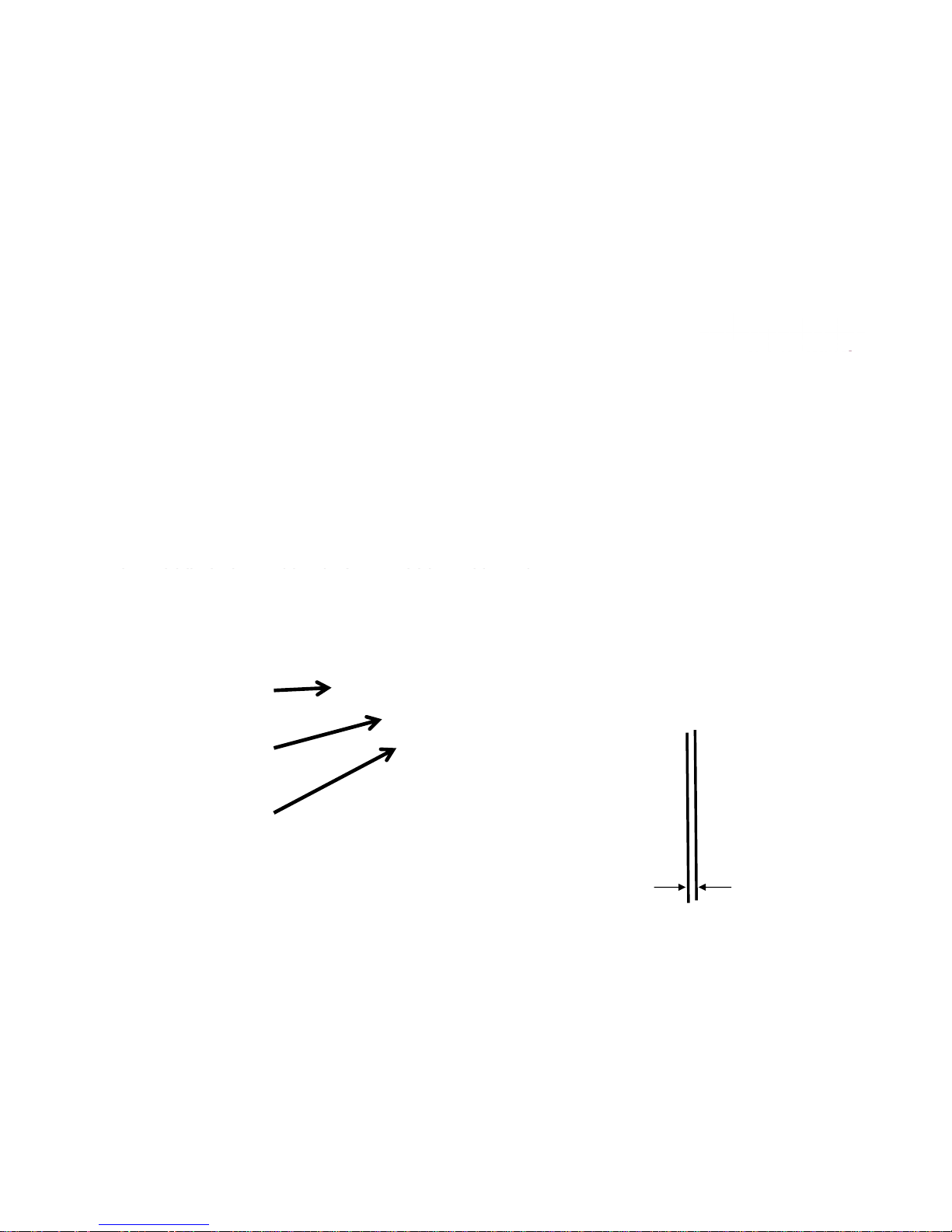
Insert the recovery tank cover gasket (Fig. 5/7) so that the seam is positioned at the front center
with a gap of approx. 1mm. The dirty drip water on the top sealing surface will be drawn into the
recovery water tank.
Fig. 5/5
Fig. 5/6
Fig. 5/7
13
Page 14
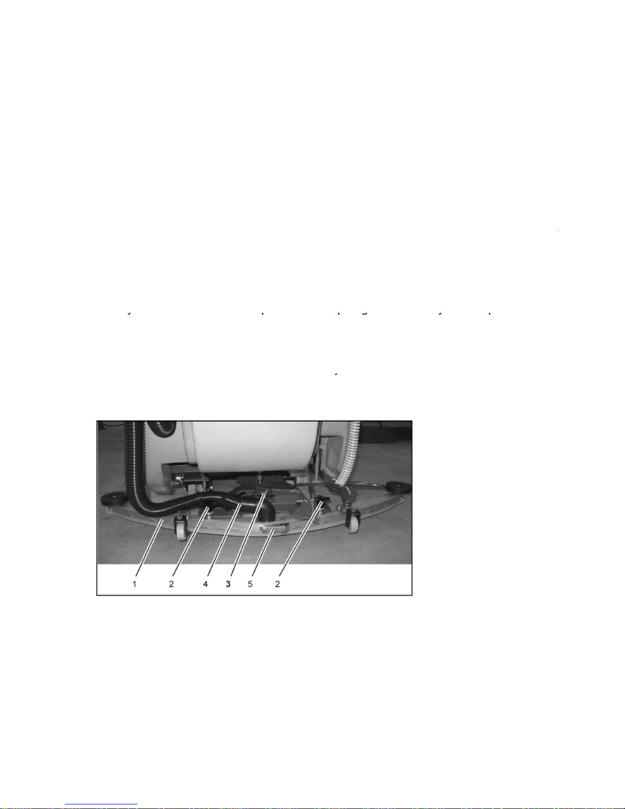
4.1 Squeegee Adjustment
V
ersion one
4.1 Squeegee Adjustment
Correct squeegee adjustment is prerequisite for optimal suction results.
Before ad
j
ustment first check the pitch of the squeegee and re-adjust if required.
jpqg
jq
1. Place machine on level ground.
2. Loosen nut of the adjustment screw (pos. 3, Fig. 5/1) and adjust sealing strips in
parallel to the floor. Turn adjustment screw clockwise: clearance between squeegee
blade and floor broadens in the center. Turn ad
j
ustment screw counter-clockwise:
j
clearance between squeegee blade and floor narrows in the center.
3. Turn machine on, lower squeegee and check drying pattern.
1 Squeegee
2 Star-shaped knob
3 Adjustment screw
4 Suction hose
5 Toggle-type fastener
Fig. 5/1
14
Page 15

4.2 Squeegee Adjustment
V
ersion Two
4.2 Squeegee Adjustment
Correct squeegee adjustment is prerequisite for optimal suction results.
Before ad
j
ustment first check the pitch of the squeegee and re-adjust if required.
jpqg
jq
1. Place machine on level ground.
2. Loosen the two bolts, located on each side (Fig 5/2A) with the squeegee attached
while holding another wrench on the location shown on Fig 5/2B. Adjust squeegee
rubbers so that the
y
are parallel to the floor, by turning the long adjustment shaft on the
yp ,y g gj
right side with an open end or adjustable wrench (Fig 5/2B). Adjust until the rear
squeegee blade folds equally accross the entire length, while moving the machine
slightly forward.
3. Ti
g
hten the two bolts on the ends while holding the center shaft with the wrench.
gg
4. Turn machine on, lower squeegee and check drying pattern.
Fig 5/2BFig 5/2A
15
Page 16
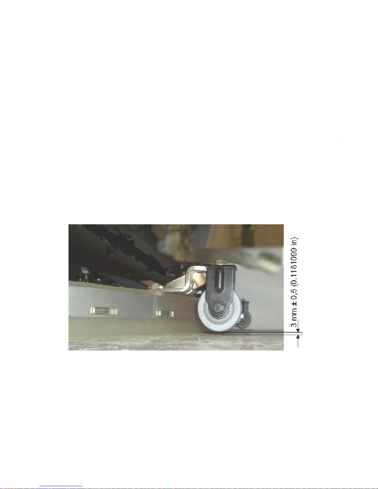
4.3 Squeegee Wheel Adjustment
4.3 The clearance between the support roller and floor with squeegee unfolded
(Factory setting) is: 0.1181099 Inches
±
0.01968498 inches (3 mm
±
0.5)
.
Note: Some floor surfaces may require adjusting the caster washers for optimum performance.
See following page.
16
Page 17
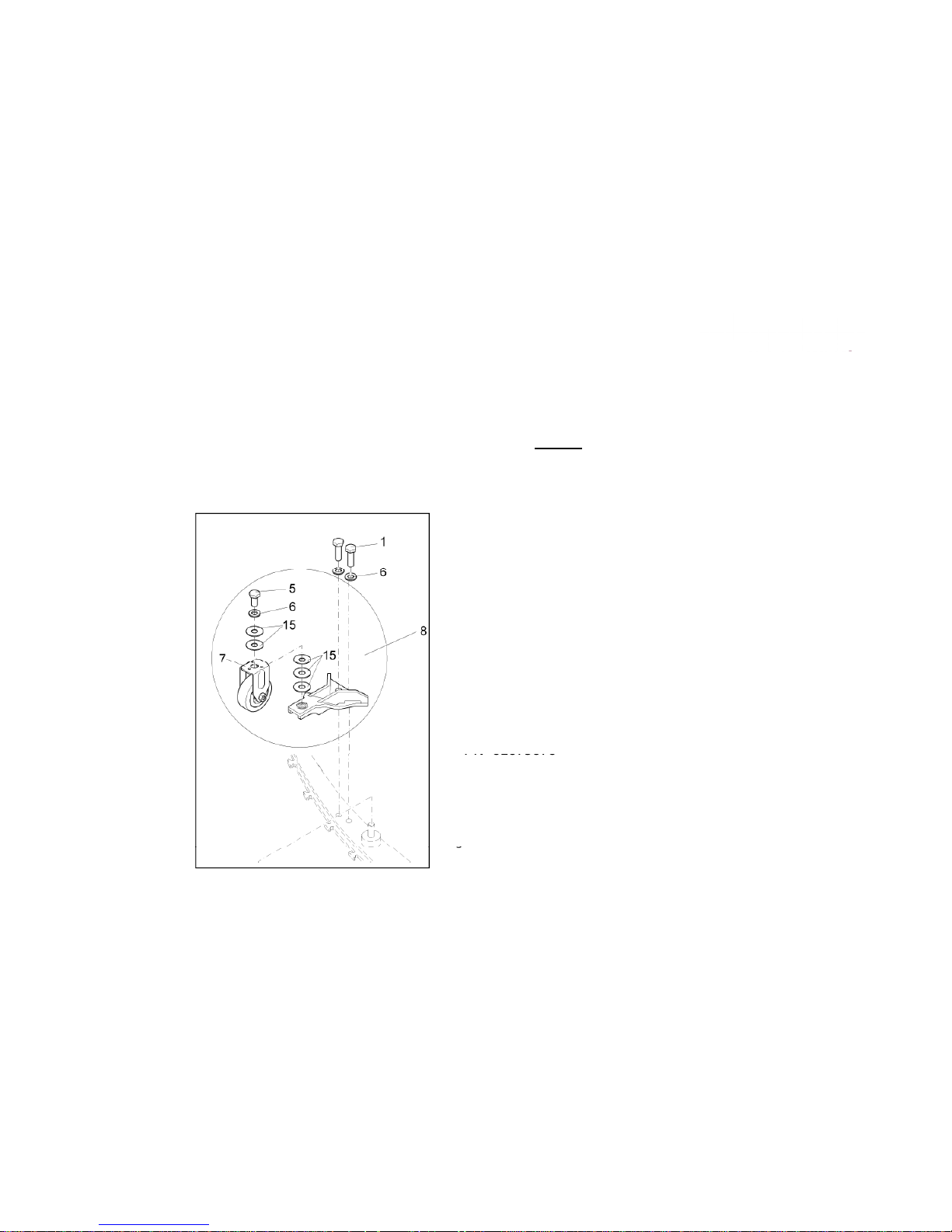
4.4 Squeegee Wheel Adjustment
4.4 Note: When adjusting the wheel height, there should always be 5 washers on each wheel
assembly position # 15 in order fully tighten bolts. Move washers from the top to the bottom of
Pos 1 – Hexagon screw M8x25 A2
PN 01059530
the bracket or visa versa when making adjustments
.
The caster controls the pressure on the
squeegee blade.
Pos 5 – Hexagon screw M8x16 A2
PN 01071740
Pos 6 – Washer B8,4
PN 00101550
Pos 7 – fixed Roller
PN 01077810
Pos 8 – Angle with fixed roller, complet
Fig. 5/3
PN 01079070
Pos 15 – Distance Washer
PN 01079080
g
17
Page 18
4.5 Squeegee Lift Cable, Switch & Motor
4.5 Squeegee Lift Cable, Lever, Micro Switch
and Vacuum Motor
•The vacuum motor micro switch is mounted
behind the squeegee lift lever (Fig. 5/4). Adjust the
micro switch so that the vacuum motor can be
turned off by lifting the squeegee by the lever.
Loosen the screws on the switch to adjust.
•Vacuum motor is switched on upon lowering of the
squeegee.
•The micro switch is a normally open switch which
is terminated to input A1.X9:3+9 on the controller.
When the squeegee is lowered, there should be
continuaty between both contacts (with the plug
A1.X9 being disconnected).
Fig. 5/4
NOTE: The squeegee lift cable spring will need to disconnected from the silver
18
lever before the squeegee lift lever plate can be removed from the machine.
Access can be made from the controller/charger area in the rear of the machine.
See Chapter 4.
Page 19

5. Brush Head (Disk) Connections
5. C
onnection of Brush Motors to Disk Brush Hea
d
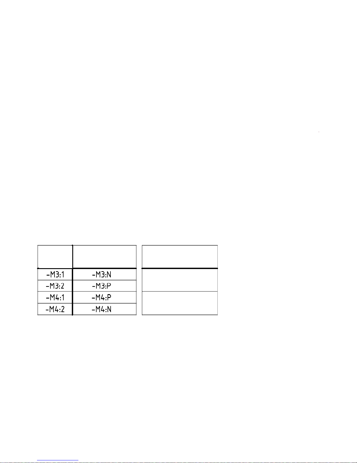
Connect the brush motors of the disk brush head in accordance with the electric diagrams. Find the
assignment of connecting stud of the motors listed in the below table. Then check the correct
direction of brush motor rotation.
The left-hand motor seen in direction of travel is M3, the right-hand one is M4.
Cable
Motor connection
Connectors
M4
M3
Harness
Disk brush
at the motor -M3/4
Stud bolt above
Connection N
Stud bolt below
Connection P
19
Page 20

5.1 Brush Motor Information
5.1 Brush Motors
The brush motors are switched on and off by a micro-switch located at the rear at the brush head
lift-out system. This switch is realised as NO (normally open) switch. To attain safe function of the
brush motors
,
correct adjustment of this switch is required.
,j q
Electric connection of the switch is realised at the central control at A1.X9:4 + 10.
Maximum current consumption of the brush motors (in practical use) must not exceed 30A per
motor on the 26 and 30“ disk brush decks. The maximum amperage for the 33“ disk decks is 40A.
Lower settings are recommended for longer motor life, run time and traction.
When checking the carbon brushes make sure that the scroll spring is pressing the carbon brush
against the commutator, does not contact the guide and that distance to carbon brush guide is
sufficient.
Replace the carbon brushes, if required.
20
Page 21
6. Brush Head
6. Brush Head Transport Position
•The lever provided is for lifting up the brush head. It features 3 positions for adjusting
the lift linkage (Fig. 6/1). The top hole is the transporting and ramp climbing position. In
this position, the lift linkage is to be adjusted so that a 1mm gap appears between the
lever and the screw head at the chassis (Fig. 6/2).
•The m
iddle hol
e pos
iti
on is for scru
bbi
ng w
ith
pads.
•The bottom hole (Fig. 6/1) is the normal scrubing position of the brush head.
Transport Position
Scrubbing position
with pads
Scrubbing position
1 mm
Fig. 6/2
21
with brushes
Fig. 6/1
Page 22

6.1 Brush Switch
6.1 Brush Switch
•The brush motors are switched on and off by a micro-switch located at the rear at the
-
brush head lift
out system Figure 6/3. This switch is a NO (normally open) switch. To
attain safe function of the brush motors, the correct adjustment of this switch is
required.
•Electric connection of the switch is connected to the central control circuit board at
A1.X9:4 + 10 connector
. In
the lifted
-
up position, the switch should open and close
when brush head is lowered.
Fig. 6/3
22
Page 23
6.2 Brush Pressure Adjustment (Disk Models)
Brush Pressure Setting on Disk models.
•
The bolt on the left can be adjusted to increase or
decrease the brush pressure.
•Models with 19 gallon tanks This pressure adjustment
will affect the models in the normal scrubbing mode. (no
extra
p
ressure option
)
Adjustment
Screw
Increase
pressure
pp)
•Models with 30 gallon tanks. This pressure adjustment
will only affect the models in the heavy pressure mode
only (second foot lever activated).
2nd notch
1st notch
•
The indicator on the right should never be set past the
second notch.
•NOTE: When making changes, the current draw should
be less than 30 amps. per motor on the 26 and 30” disk
”
decks under load maximum
. 40
amps max on 33 decks
.
•Lower settings are recommended for longer motor life,
longer run time and traction.
•Verify the current with brushes under load, with a digital
Decrease
pressure
clamp-on meter.
•Only an authorized Minuteman Service Center should
make changes to the brush pressure setting.
23
Note: The factory setting
set at the second notch
Page 24

6.3 Brush Pressure (Disk Models)
Heavy
Brush
Pressure
(2nd Foot
Specific
Surface Pressure
Model
Area Per
Brush
B
rush
Pressure
Pedal
Engaged)
Specific Surface
Pressure
with Heavy Brush
Pressure
E3330
1055 cm²
163.525 inch²
400 N =
90 lb 600 N = 135 lb 0.19 N/cm² = .275 lbs per inch²
0.28 N/cm² = .406 lbs per
inch²
²
=
²=
E3030
761 cm
1 17.955 inch²
320 N
72 lb 600 N = 135 lb 0.21 N/cm² = .35 lbs per inch²
0.39 N/cm
.
565 lbs per
inch²
E2830
280 cm²
43.400 inch²
240 N =
54 lb NA 0.43 N/cm² = .623 lbs per inch² NA
240 cm²
²
260 N =
²
²
E24
37.200
inch
58 lbNA0.54 N/cm = .783 lbs per inch
NA
E26
586.5 cm²
90.908 inch²
350 N =
79 lb NA 0.3 N/cm² = .435 lbs per inch² NA
24
Page 25
6.4 Brush Head (Cylindrical)
6.4 Electric Connections
• Connect the brush motors of the cylindrical broom head in accordance with
the electric diagrams. Find the assignment of connecting stud of the motors
listed in the below table. Then check the correct direction of brush motor
rotation.
• The left-hand motor seen in direction of travel is M3, the right-hand one is
M4.
M3 M4
Motor connection
Cyl. brush head
Cable
Harness
Connectors
at the motor -M3/4
Stud bolt above
Stud bolt below
Connection P
Connection N
25
Page 26

6.5 Adjusting Cylindrical Deck
Spacer Block on this side also
Spacer Block
26.5 mm high
Part number for the gauges are available by request.
26
Page 27

7. Drive and Wheels
7. General Data
Torque of wheel bolts: 23 foot lbs
Torque of wheel nuts: 18 foot lbs
Wheel speed in max. drive potentiometer position:
Forward: (3.1 mph) 110 min-1 Reverse: (1.55 mph) 55 min-1
Torque of setting for screws on caster mounting: 17 foot lbs
7.1 Electric Brake (E33 and 30 Gallon Tank Models Only)
•The drive motor is equipped with a electric brake on the transaxle. In the display , the
brake is represented by the symbol. The transaxle is locked (lever down) by brake as
pyy ()y
soon as the drive bail handle is in the neutral position.
Release the brake mechanically before pushing the machine. To release, unlock (lever up)
the lever located on the drive motor behind the water filter on the left side of the machine
directly behind the left-hand drive wheel.
y
•If the machine is powered up with the brake in the unlocked position the “flashing H“ will
appear in the hourmeter display. This will prevent the machine from operating for safety
reasons.
• When this occurs the coil volta
g
e will be interupted on the K1 main relay.
gp y
Resistance of the electric brake coil amounts to approx. 37 to 41 Ω.
27
Page 28

7.2 Transaxle Motor
7.2. Transaxle Drive Motor
•Drive motor, axle and differential are a single unit.
•The wheel drive is nearly maintenance-free. Check the
carbon brushes of the drive motor at regular intervals
during maintenance. Carbon brushes are worn if the
scroll spring applying the carbon brushes to the
armature, is approx. 1mm away from the guide. Contact of
the spring and the guide must be avoided since otherwise
the armature can be damaged. Before the check, remove
battery and battery tray from the machine.
•
The thermal switch of the drive motor is integrated in the motor and cannot be
replaced. Such switches are NC (normally closed) switches which interrupt the
circuit, if the motor temperature exceeds the limit. The thermal switch is
connected to the control board at A1.X9:2+8.
28
Page 29

7.3 Transaxle Motor Carbon Brushes
7.3 Carbon Brushes
Close the cover of carbon brushes again as shown in photos 7/2, 7/3
and 7/4. Make sure that the plastic lock is placed in a motor housing
recess for brushes.
29
Page 30

7.4 Drive and Wheels
7.4 Drive Potentiometer Circuit
•Potentiometer Resistance
Value: 5.875 k Ω +- 30%
•Asssignment of connecting plug (A1.X4):
Pin 1: Ground
Pin 2: 24Volts
Pin 3: Digital signal of drive direction 1
Pin 4: Digital signal of drive direction 2
Pin 5: Potentiometer wiper
Pin 6: Potentiometer +
Pin 7: Potentiometer Pin 8: not assigned
Potentiometer
30
Page 31

8. Water Supply
8.1 The solenoid valve releases or stops supply of water flowing to the brushes.
The solenoid valve is located at the front pane of the battery compartment. The
•
solenoid valve is electrically connected to the central controller A1 at
A1.X11:1+2. See Fig. 8/1
•Coil resistance of solenoid: approx. 47 Ω
•Current consumption of solenoid: approx. 0.5 A
•Water amount is regulated by ball valve on all
the 19 gallon and models.
Fig. 8/1
8.2 Solution Filter
The clear water supply line to the
brushes is equipped with a filter
screen. In case of problems with the
supplied water amount, check the
screen and the hoses from clear water
tank and to the brushes
.
See Fig.8/2
Fig. 8/2
31
Page 32

8.3 Water Supply (Solution Tank Clean out)
•The Models E33, E2830, E3030 and E3330 with the 30 tanks will be
equipped with a clean out plug on the solution tank
.
•The plug may be removed to clean out debris that is inside the tank.
32
Page 33

8.4 Solution Flow rates
WaterSetting123456
DiskBrush
30&33"
Gallonspermin
.18 .29 .36 .52 .95 1.45
P
umpVoltage
2.68
3.46
4.61
5.84
9.82
15.43
Cyl.Brush24"
Gallonspermin
.39 .47 .55 .60 .68 .74
PumpVoltage
4.69 5.99 6.85 7.47 8.45 9.24
Cyl.Brush28"
Gallonspermin
.39 .47 .55 .60 .68 .74
PumpVoltage
4.32 5.86 6.77 7.15 8.00 9.86
Note:Values areproportionaltothedrivespeedexceptforposition6
Thisinformationappliestomodelsequippedwithasolutionpumponly.
TheE26ismanuallycontrolledbytheoperator.
33
Page 34

8.5 Water Pump
8.5 Solution Control
• Models equipped with water pump
• The solution flow rate is affected by the speed of the drive
system.
• The controller adjusts the voltage to the pump to regulate water
volume.
• The faster the machine is driven the more water will flow to the
brushes
.
• The controller uses stand still recognition circuitry. The pump
will be shut off, if the water supplied to the pump is to low or
inefficient, when the voltage supplied to the pump is above the 5
,gpppp
volt level. This feature is disabled if voltage is below 5 volts.
34
Page 35

9. The Last Error
9. All Minuteman E24, E26, E2830, E30ECO, E30, E28, E3030, E3330,
E33XL, H26, H30
and 19, 24 and 30 gallon models are equipped w
ith
an
error memory which will indicate the last error that occurred in the
machine. This last error is displayed upon turning on the machine by
key switch. The first numbers that
appea
r will be the software version.
eys tc e st u best atappea bet esot ae eso
The second will be the last error (if one had occured). The third will be
the hour meter .
•If four digit error code is displayed continuously with blinking dots
and the alarm is sounding, the controller has detected a problem in the
system. The machine will be inoperable. See error codes for details.
35
Page 36

10. Table of Error Codes
Error code Error source Remarks
Chec k tem
p
eratur e of br ush motors; check
1.2.5. 2. Thermal swi tch Brush 1/2
p;
current consumption of brush motors; check
wiri ng of thermal switc h (X8 and X9 plugs) of the
brush motors (series connec ti on). Input A1. X9:1
and 7
1.2.6.1.
Blocking protection Brush 1/2 Electroni c
protection of brush motors
Brush motors smooth running? C heck cur rent
consumption? 30A max. per motor
3.1.6.E
.
Fuses of power unit
Group message all fuses on the A1
3.2.1.1. LD S defec ti ve
Is battery voltage identical to voltage at A1:X1
and A1.X2? (i dle r un and under load)
3.4.1. 1. Dri ve rheostat
Chec k dri ve rheostat and wir ing, is dr i ve rheostat
detected at the contr ollers A1X 4 connection?
3.4.1.2.
Off i sle switch on during star t up or Dr ive
Turn off off isle switch and r estar t machine
control defective
If error is permanent, replac e central controller
3.4.5.1. D ri ve motor overheated
Chec k ther mal switch and wiring from dri ve
motor, X10 plug
36
Page 37

10. Table of Error Codes
Error code Error source Remarks
Check connecting cable between central
4.5.2. 5. Co ntrol panel not r ecognized controller and contr ol panel. This error
occurs upon switching on only.
4.5.3. 5. No response control panel (Timeout)
Check connecting cable between central
controller and co ntrol p a nel. This e r ror
occurs upon switching on only.
4.6.1. 2. Int er nal cont r oller err or
If er r or is permanent and even af t er
repeated sw it ching on and off of the
machine, replace central controller
5.1.4. 1. Main contactor does not switch
Does main contactor K1 sw itc h? Check
main contactor wiring. Contacts
If er r or is permanent and even af t er
5.4.6.1.
Error upon system start (signal
states)
repeate
d
switching on and off of the
machine, replace central controller
"H"
"P"
Hand brake unlocked
Hand brake locked
See chapter 7.1
Magnet brake at dr ive motor
37
Page 38

11. 24V - 22A Charger
10.1 Operating Instructions
38
Page 39

11.1 24V - 22A Charger
39
Page 40

11.1 24V - 22A Charger
40
Page 41

11.2 Charger Error Codes
10.2 Note: The following are error indicators that could occur during the battery
charging process. All errors will be in the form of a blinking display picture
of the battery
.
The display indicator figure # 1 will display a blinking doted square, if the
battery malfunctions for the following reasons:
1. The battery has less than 1.25 volts per cell.
2. The battery has less than 15 volts after 30 minutes
3. The batteries are wired incorrectly (reversed polarity).
4. The batteries are missing.
5.Th
e wrong battery type is installed.
6. The selected programming of the charger is incorrect for the
batteries that are installed.
Fig.1
41
Page 42

11.2 Charger Error Codes
The display indicator figure # 2 will blink, when the charger timer times out.
This occurs when the battery voltage on a 24 volt battery pack does not reach
22.8
volts or higher after 30 minutes. The charger w
ill sh
ut off.
Fig. 2
The displ
ay indicator figure # 3 indicates that there is an error in the charger.
1. The charger needs repair or replacing.
Fig. 3
42
Page 43

11.2 Charger Error Codes
The display indicator figure # 4 will blink when the charger is over heating:
1. The coolin
g
air is restricted
g
2. The cooling fan is not working.
3. The cooling hose is not connected or is obstructed.
Fig. 4
Programming button depressed while starting the charging operation.
Fig. 5
43
Page 44

11.3 Trouble Shooting the Charger
•Symptom - charger has no output.
Check for loose or burnt connections on the side of the
charger.
•
Use a test cord by
-
pass the original AC power cord
.
Note: Continuity and voltage tests may not be adequate for
testing the condition of the AC cord.
•Power cords from a desk top computer will make a good test
cord.
44
Page 45

11.4 24V - 14A Charger
•10.4 Charger Maintenance Points
•Check the following, when servicing the machine:
•The charger unit should be secured by rubber strap.
•The wires going to and from the charger should be secured with plastic
gg g p
wire ties. They should be routed so that there are not any kinks, pinched
or crushed wires.
•The charger housing must be insulated from all metallic machine parts.
-
Use a multi
meter to measure the resistance between charger housing and
the frame on the machine. There should not be continuity.
•Repeat the test by checking the resistance between the A.C. Cord ground
pin of the charger and frame of the machine. There should not be
continuity
.
•The ground pin of the A.C. cord must conduct without resistance to the
screws on the charger case.
•The char
g
er ventalation hose must in place and without obstruction.
gp
45
Page 46

11.5 Programming the Charger
10.5 The automatic scrubbers are equipped with the new on board automatic charger.
The charger will be programmed from the factory for the wet lead acid batteries.
Machines that were purchased with gel maintenance free batteries installed at the
factory will be programmed for gel.
1. The charger can be programmed to charge either the gel type battery or wet lead
acid batteries.
2. Follow the instructions below to change the charging mode.
ggg
3. Remove the two Allen head screws on the rear of the machine. Let the
charger/controller-cover drop down. The charger is located on the rear of the
housing.
4. Remove the nut and washer on the backside. Carefully lift the plastic cover off
and set it to the side.
5. Plug the charger’s A.C. power cord into the outlet. The charger will turn on.
6. Locate the small push button switch on the right side of the charger. Located near
the rubber strap.
ProgrammingButton
46
Page 47

11.5 Programming the Charger Cont.
5. Push and hold the button in for 2 to 4 seconds and release. The charger will
turn off.
6. Push and hold the button in again for >10 seconds and release. This puts the
charger into the programming mode. The picture on the machine’s display will
blink rapidly indicating which charging mode has been previously stored in the
7. Push the button for <1 (one) second at a time to select a different charging
mode. The picture will blink slowly, indicating that you’re in the selection mode.
P
ush the switc
h r
epeatedly unt
il the
desired mode is displayed
.
charger
.
us t e s tc epeated y u t t e des ed ode s d sp ayed
8. The charger will show a total of 8 (eight) different charging modes. (See
pictures below for the proper mode). The remaining settings do not have any
additional functions.
47
Page 48

11.5 Programming the Charger Cont.
Mode # 5 is for gel type
batteries using chargers
Mode # 0 is for the
Trojan # 956752
Mode # 1 is for AGM
batteries 956749 (260
prior to charger serial
96117197 7 6992 6
260 Ah batteri
es for the
charger 96137732 only.
Ah) & 956200 (200 Ah)
for the charger
96137732 only.
Mode # 6 is for the wet lead acid
batteries only
. All chargers have
this setting.
Mode # 7 is for gel batteries
only
after charger serial
96117197 7 6992 6 and all
This is the
Default setting
96137732 chargers.
48
Note 1: Settings 2 ,3 and 4 are the same as 5 on the 96137732 charger.
Note 2: Settings 2, 3, 4 and 7 are the same as 5 before serial number 96117197 7 6992 6.
Note 3: Do not use other settings on chargers after serial number 96117197 7 6992 6.
Page 49

11.5 Programming the Charger Cont.
9. To save the desired mode, press and hold the button for more than 5 seconds
and release. The picture on the display will blink rapidly indicating the setting
has been stored.
10. To end the programming mode function, wait about 60 seconds. The charger
will automatically return to its normal operation.
11.Unplug the X31 jumper connector on the main control board harness for the gel
and AGM maintenance free batteries. Connect the X31 plug to the harness for
the lead acid type batteries. Secure the X31 connector with a plastic tie in the
control board area when not in use.
12. Install the plastic cover with the nut and washer.
13. Install the two screws and secure the charger/controller cover to the original
position.
X31 Plu
g
g
49
Page 50

11.6 Replacing the Charger Harness
•When replacing the charger output harness (W8) 97094346 on
19 gallon models or 011722530 on 30 gallon models with the
electric brake.
•Use the K-E24261668 Charger Retro fit kit in addition when either the
harness or charger is being replaced.
•Inspect the receptacle on the charger for burnt or damage.
Replace the charger if it is damaged.
•
Use a coating of high temperature dielectric grease
(NYOGEL 760G GREASE) or equivalent, on the pins of the plug
of the harness, before connecting the new harness to the charger.
50
Page 51

12. Batteries
12.1 Maintaining Wet Lead Acid Batteries
1. Always keep the water levels above the plates
2. Fill cells with distilled water only. Tap water can cause an
excessive
build
upofminerals
and
reduce
the
chemical
reaction
of
the batteries. This will shorten the life and performance of the
batteries.
3. Use an appropriate filling device, when filling the batteries. Do not
use a gardenhose.Floodingthebatteries canflus
h
th
eelectrolyte
out of the battery and shorten its life.
4. Fill cells 3/8 to 1/2 of an inch above the separators. Do not fill
above the fill the marker ofthe batteries. Over fillingcan cause the
g
electrolyte to percolate out onto the case while charging.
51
Page 52

12.1 Batteries
5
. Check water level daily.
Fill, if
needed.
6. Keep all the battery cable connections tight.
7. Keep all the battery posts and cables clean. Clean the battery cases
with a mixture of baking soda and water solution or commercial spray
g
py
that neutralizes the acid. Spray the cases with a water displacement
chemical or a silicone. This will help break the flow of current across
the case and reduce the discharge rate .
Note: The electrolyte on the surface of the case can cause:
A. The batteries to discharge faster even while sitting and have a shorter
run time.
B. The battery charger to stay on for extended periods. Thus causing an
over charge condition and shortening the life of the batteries.
C. Never leave batteries in a discharged state for long period of time.
52
Page 53

12.2 Load Testing Batteries
12.2 Load Testi
ng
Load test battery with an automotive type load tester. This test
puts an ampere load on the batteries and measures the voltage
at the same time. If voltage drops too low on the meter this
would indicate that the batteries are weak or discharged. Load
testing can identify dead cells, broken or disconnected plates,
and cells or charge status
.
This is good test however, it can
only detect these types of failures. See Specific Gravity Test for
additional tests.
53
Page 54

12.3 Hydrometer Testing Batteries
12.3 Hydrometer Testing on Lead Acid Wet Batteries
• Hydrometer testing can used to measure the specific gravity of deep cycle
batteries. This allows you to detect weak cells, which are causing loss of
running time. It can only detect these types problems. The hydrometer
should have specific gravity markings such as 1.265, 1.250, 1.225, and so
on.
• Hydrometers with the four balls are not accurate enough for this
test and are not recommended.
• Fully charged batteries should read 1.265 and will decrease as batteries
are discharged until they reach 1.120. This test should be done when
batteries are charged and cooled. Allow one hour or more to cool. It can
also be done after batteries are partially discharged, if they are allowed to
cool. However, you will not be able to detect the full capacity of the
battery.
54
Page 55

12.3 Hydrometer Testing Batteries Cont.
• To do an accurate test,the batterywater level must be high enoughto
,yg
g
extract enough electrolyte to fill hydrometer enough so that the
indicator floats. If the water levels are low, water should be added
prior to charging in order to let the electrolyte to mix.
• The greater the variation between cells readings, the greater the loss
of run time. For example, if the readings are 1.265, 1.265 and 1.225 in
one 6 volt battery
.
The low cell would be considered weak and greatly
reduce the performance of the battery or shorter run time. This
battery would have a point 40 variation. Batteries that have weakened
cells in most cases it can still be used as long they continue provide
adequate run time. A battery with a point 40 variation or more should
be determined defective.
55
Page 56

12.3 Batteries (Wet Lead Acid)
• Minuteman batteries are rated for 500 charge cycles.
gy
Every time the batteries are charged it uses one cycle.
To insure getting the expected life, unnecessary charging should be avoided.
• The specific gravity will reflect the percentage of charge remaining in the
battery.
• 100% charge = 1.265 and above Specific Gravity
•
=
75 % charge
1.225 Specific Gravity
• 50 % charge = 1.190 Specific Gravity
• 25 % charge = 1.120 Specific Gravity
•
N
ote : Gel maintenance free batteries can not be tested with the hydrometer.
Do not attempt to open cell covers or caps. Doing so will destroy the battery.
56
Page 57

13. Fuse Locations (Version 2 Controller)
All the fuses are located on the main
control circuit board.
Part Numbers
00059580 Fuse 125 Amp 80 Volts (Brush & Vac. Motors)
00972420 Fuse 100 Amp. 80 Volts (Brush & Vac. Motors)
00733630 F
use 10 Amp. 32 or 80 Volts (Pump & Water Sol.
)
00902440 Fuse 50 Amp. 80 Volts (Drive)
00972430 Fuse 2 Amp. 32 Volts (Switch)
Note: If the 2 amp fuse blows,
check the main contactor for
bad contacts.
Warning: Do not substitute the value
of the 50, 100 and 125 amp fuses.
They must be correct voltage and
amperage
.
Doing so will produce
system errors. Fuses are used as
shunts in the circuit.
57
Page 58

13.1 Fuse Locations (Version 3 Controller)
10 Amp Fuse
32 or 80 V olts
00733630
125 Amp Fuse
80 Volts
00059580
2 Amp Fuse
32 Volts
00972430
50 Amp Fuse
80 Volts
00902440
5 Amp Fuse
32 Volts
00906120
58
Page 59

14. Controller Connections
59
Page 60

15. Trouble Shooting the Controller
Note: If the 5 amp fuse on the controller blows, It could indicate:
1. A faulty contactor (not closing on the negative side).
2. Poor connection on the battery negative side of the contactor.
3. Poorly crimped terminals on the contactor connections.
-
4.
Incorrect wiring of the contactor. (See chapter 16
17)
• NOTE - Always use a coating of high temperature dielectric
grease (NYOGEL 760G GREASE) or equivalent on the motor
connectors on the bottom of the controller when replacing the
board or motor harnesses.
Caution: Connecting the battery pack polarity
60
incorrectly will permanently damage the controller.
Page 61

16. Contactor Wiring – Harness
61
Page 62

17. Contactor Wiring
Proper wiring of the
contactor is critical
Control Board
To batteries
and charger
62
Page 63

18. Testing the Main Power Relay
B-
Digital Volt M
ete
r
F
rom Batter
y
B+
From Battery
gta ot ete
B-
25 Volts
Controlled
B+
Controlled
Note: Measure the voltage across the
B+ and the B- coil terminals with the
wires attached and the key switch
turned on. It should be about 24 volts.
If
not, poss
ible l
ow battery con
diti
on.
Inspect batteries.
Diode
63
Page 64

18. Testing the Main Power Relay
B
-
From Battery
B+
From Battery
Digital Volt Met
er
25 Volts
+
B
-
Controlled
OR
B
Controlled
Note: Measure the voltage from a battery negative
source to the B+ terminal of the main relay’s coil to
-
+
determined of the B+ is being supplied to the coil. It
should be 24 volts. If not, inspect control board and
key switch circuit
+-
Batteries
64
Page 65

18. Testing the Main Power Relay
Digital Volt M
ete
r
B-
From Battery
B+
From Battery
gta ot ete
B-
25 Volts
+
Controlled
OR
B
Controlled
Note: Measure the voltage from the battery positive
source to the B- terminal of the main relay’s coil to
-
-
+
determined of the B
is being supplied to the coil. It
should be 24 volts. If not, possible blown 5 amp fuse or
relay or key switch circuit problem. Also check
connections on the on-board charger
+-
Batteries
65
Page 66

18. Testing the Main Power Relay
25.5 vol
ts
Note: Measure the
voltage on the
incoming battery side
55 ots
across the B+ & Bterminals when the
machine is powered
up and under load.
B-
From Battery
B+
From Battery
p
B-
B+
Controlled
Controlled
66
Page 67

18. Testing the Incoming Contact Voltage
on the Main Power Relay
22.4
y
Note: The
voltage should
The relay is
defective
-
volts
Volt Meter
b
e exactly the
same as the
Note: The incoming
voltage was 25.5
+
battery side
when the
machine is
volts
under load.
B+
Controlled
B-
Controlled
67
Page 68

Page 69

Page 70

Page 71

Page 72

Page 73

Page 74

Page 75

1174-00
PLOTDATUM : B-Stand : 003 / Ri. / 19.12.07 [004 / kupe / 19.12.07]19.12.2007
-X25
-X1
97098511
-W11
-X26
-G2
-G2.X3:-G2.X2:-G2.X4:
-G2.X1:
-G1
97096986
-W1
-X24
97094346
-W8
-X18
-M7
-K1
-X19
99-7036-50
97094346
-W8
-Y1
-X102
-X101
-S11
97099063
-W9
97094304
-W6
97101547
-W3
-X31
97096721
-W12 (option spray tool)
-A1
-A1.X9:
-A1.X8:
-A1.X21: -A1.X34:
-A1.X20:
-A1.X4:
-A1.X22:
-A1.X1: -A1.X2:
-A1.X11:
connected (state of deliver):
battery type Gis (wet)
disconnected:
battery type GiV (dry)
-S1
-A2
-A2.X1:
-A2.X7:
-A2.X5: -A2.X6:
-S7
97096994
-W2
-S5
-A3
-S6
97099071
-W16
-M3
-M4
-M3.S1
θ
-M4.S1
θ
-X12
-X32
97097786
-W14
-R1
-S4
notice:
-M1
-X8
-M2
-X10
97098503
-W13
-M1.S1
θ
-S3
-X9
97101547
-W3
214
3
Blatt:Blattzahl:Normgepr.
Datum Name
Gezeichnet
Geprüft
NameDatumÄnd.-Nr.Nr.
VES-Nr. :
Ersatz für :
Änd. Nr. :
Benennung
Typ:
Zeichnungs-Nr.
Hako-Werke GmbH
D-23840 Bad Oldesloe
31
Gl.Nr.
1066-00
07.06. kupe19.12.07 Ri.
2007
2 ./.
A1
-A1.X9:5
-K1:1 -G1:P(+)
P
35mm²
-K1:3 -G1:N(-)
on-board-charger
supply main
1 2 12 123456
-K1:1
4mm²
N
-A1.X9:12
-X1:PB
P(+)
N(-)
-X1:NB
-K1:3
4mm²
35mm²
1
-A1.X11:12-A1.X11:6
-A1.X21:1
-A1.X21:2
0,75mm²
-A1.X8:2
-A1.X21:5
-X1:PS-A1.X1:
-A1.X21:7
4mm²
-G2.X4:1
-A1.X21:4
-A1.X21:6
0,75mm²
-A1.X8:4-A1.X11:4-M7:RD
water
pump
RD
BK
-A1.X21:8
-X1:NS
4
3A1
A2
1
2
-A1.X2:
-A1.X21:3
4mm²
-G2.X4:2
-A1.X11:9-M7:BK
0,75mm²
-A1.X8:3-A1.X8:1
35mm²
35mm²
0,75mm²
water valve
option
spray tool
-A1.X11:3
1
2
-A1.X11:8
virtual ground
at direction switch
-X101:
1mm²
-X102:
virtual ground
at chassis
-A2.X6:1
spray tool on
-A2.X6:2
0,75mm²
0,5mm²
0,5mm²
0,75mm²
-G2.X3:6
-G2.X3:5
-G2.X3:4
-G2.X3:3
-G2.X3:2
-G2.X3:1
-G2.X2:2
-G2.X2:1
-K1:A1
-K1:A2
-K1:1
-K1:3
-X8:1B
-X9:2B
-X10:1B
-X10:2B
-S3:1
-S3:2
-S4:1
-S4:2
-X25:B
-X26:B
-X31:1B
-X31:2B
-A1.X9:6
-A1.X9:13
1
2
-X31:2S
-X31:1S
35mm²
-Y1:1
-Y1:2
0,5mm²
-K1:2
controller
3
10
4
11
1
8
2
9
5
12
6
13
F1
125A
2
4
3
1
1
2
5
7
4
6
8
3 1
2
3
4
5
6
1
2
1
2
3
4
5
6
7
8
F2
50A
LOGIC
F6
10A
F5
2A
LOGIC
LOGIC
LOGIC
38 49 16510
LOGIC LOGIC
27
7
14
LOGIC
VCC2
F3 5A
-X18:S
-X19:B
35mm²
0,5mm²
-K1:4
-X24:1B
-X24:2B
-M3:1
-M3:2
-M4:1
-M4:2
-X12:1B
-X12:2B
-M1:BK
-M1:RD
-S5:NO
-S6:3
-S6:1
-X32:3B
-S7:C
-X32:2B
6mm²
6mm²
2,5mm²
-A2.X5:1
key
switch
BAT
control
panel
21 12
-X32:1B
dead man
switch right
C
NO NC
-A1X4:6
-A2.X5:2
-S1:
-S1:BAT
-A1.X4:1
dead man
switch left
C
NO NC
-S6:2
key
board
-A1.X4:3
6mm²
6mm²
6mm²
6mm²
-S5:C
2
13
direction
switch
+
-
2,5mm²
-A1.X4:4
brush-
motor
left
brush-
motor
right
0,5mm²
0 1
-A1.X34:1-A1.X34:2-A1.X34:3-A1.X34:4
-S11:
-S11:
-X8:1S-X8:2S-X9:1S-X9:2S
-A1.X34:5
-A1.X34:6
-S7:NO
-A1.X4:5
-A1.X4:7
1
2
1
3
2
-M2:GY
-M2:BK
-R1:
-R1:
-R1
+
-
drive
motor
speed giver
-A1.X9:11
0,75mm²
-A1.X9:4
brush
on
1
24
loom of cables -W13 (97098503) and loom of
cables -W14 (97097786) only for cylindrical
scrub brush. For conical brush connect the wires
of thermal switches direct at -X8 and -X9.
0,75mm²
BK
RD
1
-M3.S1:-A1.X9:1
suction motor
2
-M3.S1:-X9:1B
GY
BK
1
-M1.S1:-A1.X9:2
2
-A1.X9:10
-M1.S1:-A1.X9:9-A1.X9:3
suction
on
1
24
1
-M4.S1:-X8:2B2-M4.S1:-A1.X9:7
0,5mm²
connection conical brush
at motor -M3/4
binder plug topside
connection N
binder plug below
connection P
-M3:1
-M3:2
conical brushmarking
cylindrical
-M3:N
-M3:P
motor connection
cable
-M3:N
-M3:P
-M4:1
-M4:2
-M4:P
-M4:N
-M4:N
-M4:P
scrub brush
91026567
91026567
=
+
wiring diagram E2833
M
-
-
-
-
-
-
-
-
-
connector -X31
M
M
M
M
topview -K1
Für diese Zeichnung behalten wir uns alle Rechte vor.(Gemäß DIN 34) 7062-12/15/18
1 2 3 4 5 6 7 8 91011121314151617181920212223242526272829303132333435 363738 39
Zahl kommt vor
0,1
0
Page 76

1174-00
003 / Ri. / 19.12.07 [ 004 / kupe / 19.12.07 ]date of plot:
-A1 controller /1.2090541483
-A2 control panel /1.2690487216
-A3 key board /1.2990487232
-G1 battery /1.3
-G2 on-board-charger /1.397097679
-K1 main contactor /1.990529942
-M1 drive motor /1.3690526021
-M1.S1 thermal switch drive motor /1.37to -M1
-M2 suction motor /1.3797096200
-M3 conical brush motor left 750 /1.3190507476
or conical brush motor left 850 90507484
or cylindrical brush motor left 700 90417056
-M3.S1 thermal switch brush motor left /1.33to -M3
-M4 conical brush motor right 750 /1.3190507476
or conical brush motor right 850 90507484
or cylindrical brush motor right 700 90417056
-M4.S1 thermal switch brush motor right /1.33to -M4
-M7 water pump /1.897047310
-R1 speed giver /1.3497100416
-S1 key switch /1.2690323437
-S3 suction on /1.3790306002
-S4 brush on /1.3590306002
-S5 dead man switch left /1.2890520446
-S6 direction switch /1.3090516147
-S7 dead man switch right /1.2690520446
-S11 spray tool on (OPTION spray tool) /1.1390224650
19.12.2007
-X1 battery connector 160A /1.2
-X8 connector 2 poles /1.36
-X9 connector 2 poles /1.38
-X10 connector 2 poles /1.37
-X12 connector 2 poles /1.33
-X18 connector 1 poles /1.8
-X19 connector 1 poles /1.9
-X24 connector 3 poles /1.4
-X25 connector 1 poles /1.1
-X26 connector 1 poles /1.3
-X31 connector 2 poles /1.18
-X32 connector 3 poles /1.33
-X101 connection virtual ground at chassis /1.13
-X102 connection virtual ground at direction switch /1.13
-Y1 water valve /1.1290435595
page
pa.
19.12.07 Ri.
Gl.Nr.
1066-00
2007
2
A3
1x
2
circuit diagram
91026567
91026567
E2833
ref. designation pathpart no
ref. designation pathpart no
modified no. date
date
drawn by
checked
name
2
3
07.06.
=
+
D-23840 Bad Oldesloe
no.
name
indemnity for:
modified no.:
kupe
Hako-Werke GmbH
no. available
Page 77

1174-00
PLOTDATUM : B-Stand 003 / Ri. / 19.12.07 004 / kupe / 19.12.0719.12.2007
-X101
-S3
-S5
-A3
-X32
-K1
-S7
-X102
-R1
-S4
driving direction
-A1
-G2
-A3 -A3
-M2
-X12
-M2
-X12
-X1
-X1
-G1
-G1
-X10
-X10
-M1
-M1.S1
-M1
-M1.S1
-M7
-M7
-M3
-M3.S1
-M3
-M3.S1
-M4
-M4.S1
-M4
-M4.S1
-A2
-A2
-A2
Blatt:Blattzahl:Normgepr.
Datum Name
Gezeichnet
Geprüft
NameDatumÄnd.-Nr.Nr.
VES-Nr. :
Ersatz für:
Änd. Nr. :
Benennung
Typ:
Zeichnungs-Nr.
Hako-Werke GmbH
D-23840 Bad Oldesloe
33
Gl.Nr.
1066-00
07.06. kupe19.12.07 Ri.
2007
A2
2
1x
-S6
-X25
-X26
-X24
-X31
-S1 -S11
-S1 -S11 -S1 -S11
-S6
-S6
-S3 -S3
-X18
-X19
-X18
-X19
-Y1
-Y1
91026567
91026567circut diagram
=
+
E2833
2
top view of battery block
-
+
+
-
+
+
Für diese Zeichnung behalten wir uns alle Rechte vor.(Gemäß DIN 34) 7062-12/15/18
1 2 3 4 5 6 7 8 9 10 11 12 13 14 15 16 17 18 19 20 21 22 23 24 25 26 27 28
Zahl kommt vor
-X8
-X9
-X8
-X9
machine with conical brush
machine with cylindrical brush
Page 78

1177-02
PLOTDATUM : B-Stand : 001 / Ri. / 12.12.07 [002 / kupe / 12.12.07]12.12.2007
-K1
-X1
-G1
24 V
-X1
-K1
-G2
-G2.X3:-G2.X2:-G2.X4:
-G2.X1:
-S3
-S4
-K1
-X25 -X26
-X27
-X31
-Y1
-A1
-A1.X9:
-A1.X8:
-A1.X21: -A1.X34:
-A1.X20:
-A1.X4:
-A1.X22:
-A1.X1: -A1.X2:
-A1.X11:
-X18
-M7
-X19 -X24
-X12
-S7
-M3
-M4
-X32
-M2
-R1
-M3.S1
θ
-M4.S1
θ
-A2
-A2.X1:
-A2.X7:
-A2.X5: -A2.X6:
-X8
-X8
-X9
-X9
-S1
-M1
-M1.S1
θ
-S5
-S6
-A3
99-7036-50
-S11
-M1.Y1
-X17
-M1.S2
-X10
Blatt:Blattzahl:Normgepr.
Datum Name
Gezeichnet
Geprüft
NameDatumÄnd.-Nr.Nr.
VES-Nr. :
Ersatz für :
Änd. Nr. :
Benennung
Typ:
Zeichnungs-Nr.
Hako-Werke GmbH
D-23840 Bad Oldesloe
21
05.11. kupe12.12.07 Ri.
2007
0 Eingeführt lt.
A1
10
2
1
P
P(+)
N(-)
N
10
4
3
on-board-charger
supply main
1 2 12 123456
suction on
1
24
brush on
1
24
A1
A2
11
1
connected (state of deliver):
battery type Gis (wet)
disconnected:
battery type GiV (dry)
battery select
12
water valve
1
2
controller
3
10
4
11
1
8
2
9
5
12
6
13
F1
125A
2
4
3
1
1
2
5
7
4
6
8
3 1
2
3
4
5
6
1
2
1
2
3
4
5
6
7
8
F2
50A
LOGIC
F6
10A
F5
2A
LOGIC
LOGIC
LOGIC
38 49 16510
LOGIC LOGIC
27
7
14
LOGIC
VCC2
F3 5A
1
water
pump
RD
BK
112
1
2
brush
motor
left
brush
motor
right
dead man
switch right
C
NCNO
1
3
2
suction motor
GY
BK
+
-
speed giver
control panel
21 12
drive-
motor
1
2
1
2
key switch
BAT
BK
RD
forward
reverse
dead man
switch left
C
NO NC
2
13
direction switch
key
board
cable
marking
-M3:1
-M3:2
-M4:1
-M4:2
+
-
motor connection
conical brush
-M3:N
-M3:P
-M4:P
-M4:N
0 1
option
spray tool
spay tool on
connection conical brush
at motor -M3/4
binder plug topside
connection N
binder plug below
connection P
213
1
2
4
91026906
91026906
=
+
connec. scheme E 33 / Ph 35
-
-
-
-
-
-
-
-
-
M
M
M
M
M
Für diese Zeichnung behalten wir uns alle Rechte vor.(Gemäß DIN 34) 7311-23/-24
1 2 3 4 5 6 7 8 91011121314151617181920 21222324252627282930313233 3435363738 39
Zahl kommt vor
0,1
0
Page 79

1177-02
B-Stand : 001 / Ri. / 12.12.07 [ 002 / kupe / 12.12.07 ]date of plot:
-A1 controller E24 / E26 /1.18
-A2 control panel /1.28
-A3 key board /1.30
-G1 battery /1.2
-G2 on-board-charger /1.6
-K1 main contactor /1.10
-M1 drive motor /1.29
-M1.S1 thermal switch drive motor /1.30
-M1.S2 brake switch drive motor /1.37
-M1.Y1 brake drive motor /1.35
-M2 suction motor /1.26
-M3 conical brush motor left /1.25
-M3.S1 thermal switch brush motor left /1.27
-M4 conical brush motor right /1.25
-M4.S1 thermal switch brush motor right /1.27
-M7 water pump /1.19
-R1 speed giver /1.26
-S1 key switch /1.29
-S3 suction on /1.7
-S4 brush on /1.9
-S5 dead man switch left /1.30
-S6 direction switch /1.30
-S7 dead man switch right /1.25
-S11 spray tool on (OPTION spray tool) /1.33
-Y1 water valve /1.17
12.12.2007
Blatt
Bl.
12.12.07 Ri.
Bennenung :
2007
0
A3
Eingeführt lt.
connection scheme
91026906
ref.
designation path ref. designation path
91026906
E 33 / Ph 35
Änd.-Nr. Datum
Datum
Gezeichnet
Geprüft
Normgepr.Name
2
2
05.11.
=
+
D-23840 Bad Oldesloe
Nr.
Name
VES-Nr. :
Ersatz für :
Änd. Nr. :
kupe
Hako-Werke GmbH
Zahl kommt vor
Page 80

1177-02
PLOTDATUM : B-Stand : 001 / Ri. / 12.12.07 [002 / kupe / 12.12.07]12.12.2007
-X25
-X1
97098511
-W11
-X26
-G2
-G2.X3:-G2.X2:-G2.X4:
-G2.X1:
-G1
97096986
-W1
-X24
97094346
-W8
-X18
-M7
-K1
99-7036-50
-X19
97094346
-W8
-Y1
-S11
-X27
-X102
-X101
97101869
-W9
97094304
-W6
97101547
-W3
-X31
97096721
-W12 (option spray tool)
-A1
-A1.X9:
-A1.X8:
-A1.X21: -A1.X34:
-A1.X20:
-A1.X4:
-A1.X22:
-A1.X1: -A1.X2:
-A1.X11:
connected (state of deliver):
battery type Gis (wet)
disconnected:
battery type GiV (dry)
-S1
-A2
-A2.X1:
-A2.X7:
-A2.X5: -A2.X6:
-S7
97096994
-W2
-S5
-A3
-S6
97099071
-W16
-M3
-M4
-M1
-M3.S1
θ
-M4.S1
θ
-X10
-M1.S1
θ
-X32
-X12
-R1
-X17
-S4
-M1.Y1
-X8
-X9
-M1.S2
-M2
-S3
97101547
-W3
97101869
-W9
214
3
Blatt:Blattzahl:Normgepr.
Datum Name
Gezeichnet
Geprüft
NameDatumÄnd.-Nr.Nr.
VES-Nr. :
Ersatz für :
Änd. Nr. :
Benennung
Typ:
Zeichnungs-Nr.
Hako-Werke GmbH
D-23840 Bad Oldesloe
31
09.11. kupe12.12.07 Ri.
2007
0 Eingeführt lt.
A1
-A1.X9:5
-K1:1 -G1:P(+)
P
35mm²
-G1:N(-)-K1:3
on-board-charger
supply main
1 2 12 123456
-K1:1
4mm²
N
-A1.X9:12
-X1:PB
P(+)
N(-)
-X1:NB
-K1:3
4mm²
35mm²
1
-A1.X11:12-A1.X11:6
-A1.X21:1
-A1.X21:2
0,75mm²
-A1.X8:2
-A1.X21:5
-X1:PS-A1.X1:
-A1.X21:7
4mm²
-G2.X4:1
-A1.X21:4
-A1.X21:6
0,75mm²
-A1.X8:4-A1.X11:4-M7:RD
water
pump
RD
BK
-A1.X21:8
-X1:NS
4
3A1
A2
1
2
-A1.X2:
-A1.X21:3
4mm²
-G2.X4:2
option
spray tool
-A1.X11:9-M7:BK
-X17:4B-A1.X8:1
0,75mm²
35mm²
35mm²
water valve
-A1.X11:3
1
2
-A1.X11:8-A2.X6:1
spray tool on
-A2.X6:2
virtual ground
at direction switch
-X101:
1mm²
-X102:
virtual ground
at chassis
0,75mm²
-A1.X8:3-X17:3B
0,75mm²
0,5mm²
0,5mm²
0,75mm²
-G2.X3:6
-G2.X3:5
-G2.X3:4
-G2.X3:3
-G2.X3:2
-G2.X3:1
-G2.X2:2
-G2.X2:1
-X27:B
-K1:A2
-K1:1
-K1:3
-X8:1B
-X9:2B
-X10:1B
-X10:2B
-S3:1
-S3:2
-S4:1
-S4:2
-X25:B
-X26:B
-X31:1B
-X31:2B
-A1.X9:6
-A1.X9:13
1
2
-X31:2S
-X31:1S
35mm²
-Y1:1
-Y1:2
0,5mm²
-K1:2
controller
3
10
4
11
1
8
2
9
5
12
6
13
F1
125A
2
4
3
1
1
2
5
7
4
6
8
3 1
2
3
4
5
6
1
2
1
2
3
4
5
6
7
8
F2
50A
LOGIC
F6
10A
F5
2A
LOGIC
LOGIC
LOGIC
38 49 16510
LOGIC LOGIC
27
7
14
LOGIC
VCC2
F3 5A
-X18:S
-X19:B
35mm²
-X17:1B
-X17:2B
0,5mm²
-K1:4
-X24:1B
-X24:2B
-M3:1
-M3:2
-M4:1
-M4:2
-X12:1B
-X12:2B
-M1:BK
-M1:RD
-S5:NO
-S6:3
-S6:1
-X32:3B
-S7:C
-X32:2B
6mm²
6mm²
2,5mm²
-A2.X5:1
key
switch
BAT
control
panel
21 12
-X32:1B
dead man
switch right
C
NO NC
-A1X4:6
-A2.X5:2
-S1:
-S1:BAT
-A1.X4:1
dead man
switch left
C
NO NC
-S6:2
key
board
-A1.X4:3
-S5:C
2
13
direction
switch
6mm²
6mm²
6mm²
6mm²
-A1.X4:4
+
-
brush-
motor
left
brush-
motor
right
0,5mm²
drive motor
0 1
-A1.X34:1-A1.X34:2-A1.X34:3-A1.X34:4
2,5mm²
BK
RD
-S11:
-S11:
1
-M1.S1:-A1.X9:2
-S7:NO
-A1.X4:5
-A1.X4:7
1
3
2
-R1:
-R1:
-R1
2
-M1.S1:-A1.X9:12
-A1.X34:5
-A1.X34:6
1
2
-M2:GY
-M2:BK
+
-
speed giver
-A1.X9:11
1
cable
marking
-M3:1
-M3:2
-M4:1
-M4:2
-A1.X9:4
brush
on
1
24
-M1.Y1:-A1.X11:5
2
motor connection
conical brush
-M3:N
-M3:P
-M4:P
-M4:N
-M1.Y1:-A1.X11:10
-M3.S1:
-M3.S1:
-M4.S1:
-M4.S1:
1
2
1
2
-A1.X9:1
-X9:1B
-X8:2B
-A1.X9:1
suction motor
3
-M1.S2:-X27:S
GY
BK
-A1.X9:10
-A1.X9:3
suction
on
1
24
4
-M1.S2:-K1:A1
connection conical brush
at motor -M3/4
binder plug topside
connection N
binder plug below
connection P
0,5mm²
0,75mm²
91026898
91026898
=
+
wiring diagram E 33 / Ph 35
M
-
-
-
-
-
-
-
-
-
connector -X31
M
M
M
M
topview -K1
Für diese Zeichnung behalten wir uns alle Rechte vor.(Gemäß DIN 34) 7311-23/-24
1 2 3 4 5 6 7 8 91011121314151617181920 21222324252627282930313233 3435363738 39
Zahl kommt vor
0,1
0
Page 81

1177-02
001 / Ri. / 12.12.07 [ 002 / kupe / 12.12.07 ]date of plot:
-A1 controller E24 / E26 /1.2090541483
-A2 control panel /1.2690487216
-A3 key board /1.2990487232
-G1 battery /1.3
-G2 on-board-charger /1.397097679
-K1 main contactor /1.990529942
-M1 drive motor /1.3290539750
-M1.S1 thermal switch drive motor /1.33to -M1
-M1.S2 brake switch drive motor /1.37to -M1
-M1.Y1 brake drive motor /1.35to -M1
-M2 suction motor /1.3797096200
-M3 conical brush motor left 850 /1.3190507484
-M3.S1 thermal switch brush motor left /1.33to -M3
-M4 conical brush motor right 850 /1.3190507484
-M4.S1 thermal switch brush motor right /1.33to -M4
-M7 water pump /1.897047310
-R1 speed giver /1.3497100416
-S1 key switch /1.2690323437
-S3 suction on /1.3790306002
-S4 brush on /1.3590306002
-S5 dead man switch left /1.2890520446
-S6 direction switch /1.3090516147
-S7 dead man switch right /1.2690520446
-S11 spray tool on (OPTION spray tool) /1.1290224650
-X1 battery connector 160A /1.2
-X8 connector 2 poles /1.37
-X9 connector 2 poles /1.37
-X10 connector 2 poles /1.33
-X12 connector 2 poles /1.34
-X17 connector 4 poles /1.35
-X18 connector 1 poles /1.8
-X19 connector 1 poles /1.9
-X24 connector 3 poles /1.4
-X25 connector 1 poles /1.1
-X26 connector 1 poles /1.3
-X27 connector 1 pole /1.13
-X31 connector 2 poles /1.18
-X32 connector 3 poles /1.33
-X101 connection virtual ground at chassis /1.13
12.12.2007
-X102 connection virtual ground at direction switch /1.13
-Y1 water valve /1.1290435595
page
pa.
12.12.07 Ri.
2007
0
A3
Eingeführt lt.
circuit diagram
91026898
91026898
E 33 / Ph 35
ref. designation pathpart no
ref. designation pathpart no
modified no. date
date
drawn by
checked
name
2
3
09.11.
=
+
D-23840 Bad Oldesloe
no.
name
indemnity for:
modified no.:
kupe
Hako-Werke GmbH
no. available
Page 82

1177-02
PLOTDATUM : B-Stand 001 / Ri. / 12.12.07 002 / kupe / 12.12.0713.12.2007
-X101
-S3
-S5
-A3
-X32
-K1
-S7
-X102
-R1
-S4
driving direction
-A1
-G2
-A3
-M2
-X12
-X1
-G1
-X10 -X17
-M1
-M1.S1
-M1.S2
-M1.Y1
-M7
-M3
-M3.S1
-M4
-M4.S1
-A2
-A2
Blatt:Blattzahl:Normgepr.
Datum Name
Gezeichnet
Geprüft
NameDatumÄnd.-Nr.Nr.
VES-Nr. :
Ersatz für:
Änd. Nr. :
Benennung
Typ:
Zeichnungs-Nr.
Hako-Werke GmbH
D-23840 Bad Oldesloe
33
09.11. kupe12.12.07 Ri.
2007
A2
0
Eingeführt lt.
-S6
-X25
-X26
-X24
-X31
-S1
-X27
-S11
-S1 -S11
-S6
-S3
-X18
-X19
-Y1
91026898
91026898circut diagram
=
+
E 33 / Ph 35
top view of battery block
+
+
-
+
-
+
Für diese Zeichnung behalten wir uns alle Rechte vor.(Gemäß DIN 34) 7311-23/-24
1 2 3 4 5 6 7 8 9 10 11 12 13 14 15 16 17 18 19 20 21 22 23 24 25 26 27 28
Zahl kommt vor
-X8
-X9
Page 83

21. Notes
83
 Loading...