

Page 1
All E17BD, E17TD, E20S, E20BD, E20TD,
E20C, H20BD, H20TD E26ECOS and
E26ECO Automatic Scrubbers
Service Manual
For:
Training
Troubleshooting
Adjustments
Revised 02/10/2019
Page 2

Contents
1 Safety Page 5
2 Technical Specifications Page 6
2.1 Dimensions E17BD & E20BD Page 7
2.2 Dimensions E17TD & E20TD Page 8
3 Maintenance Intervals Page 9
3.1 Customer Maintenance Page 10
3.2 Maintenance I after every 125 hours of operation Page 11
3.3 Maintenance II after every 250 hours of operation Page 12
3.4 Maintenance S after every 500 hours of operation Page 13
4 Batteries and Wiring Page 14
5 Recovery Float and Gasket Page 15
6 Lubrication Page 16
7 Charge Indicator Version 1 Page 17
8 On Board Chargers (957760 and 957761) (Ver. 1 & 2) Page 18
8.1 Programming the 957745 Charger Page 19
8.2 Charger Settings (957745) Page 20
8.3 Battery Charger Trouble Shooting Page 21
8.4 Battery Charger Error Codes 957745 (Ver. 1) Page 25
8.5 Programming The 957760 & 957761 Charger (Ver. 2) Page 26
8.6 Charger Error Codes 957760 & 957761 Page 27
Page 3

Contents
8.7 Prime Chargers Page 29
8.8 Prime Charging Status Indicator Page 30
8.9 Prime Charger Fault Codes Page 31
9 Battery and Error Code Indicator Page 32
9.1 E17TD and E20TD Error Codes Page 33
10 Trouble Brush Motor Controller (Sport only) Page 38
11 Squeegee Adjustment (Curved) Page 39
11.1 Squeegee Adjustment Page 40
11.2 Squeegee Caster Adjustment Page 41
11.3 Squeegee Caster Adjustment Page 42
11.4 Squeegee Caster Adjustment Page 43
12 Maintaining Deep Cycle Wet Batteries Page 44
13 Load Testing The Batteries Page 46
14 Hydrometer Testing Page 47
15 Transporting the Machine Page 50
16 Key Switch Page 51
17 Solution Filter (new and old) Page 52
18 Testing the Main Power Relay Page 54
Page 4

19. Trouble Shooting the Drive Circuit Page 59
19.1 Trouble Shooting The Traction Drive Switch Page 60
19.2 Trouble Shooting – Vacuum Motor Circuit Page 61
19.3 Trouble Shooting – Vacuum Relay Page 62
19.4 Testing the Drive System Potentiometer Page 63
20 Notes Page 64
Contents
Page 5

1. Stop the machine only on level surfaces.
2. Avoid moving parts. Do not wear loose jackets, shirts, or
sleeves when working on machine.
3. Avoid contact with battery acid. Battery acid can cause
burns. When working on or around batteries, wear protective
clothing and safety glasses. Remove metal jewelry. Do not
lay tools or metal objects on top of the batteries.
4. Do not clean machine with a pressure washer.
5. Only authorized personnel should perform repairs and
maintenance.
6. Use only Minuteman genuine replacement parts.
8. Do not use machine around flammable substances.
9. The batteries should be charged only in well ventilated areas.
10.Always disconnect the battery pack from the machine and the
A.C cord the from outlet, when servicing the machine.
1. Safety
Page 5
Page 6

2. Technical Specifications
E17BD, E20
Page 6
Page 7
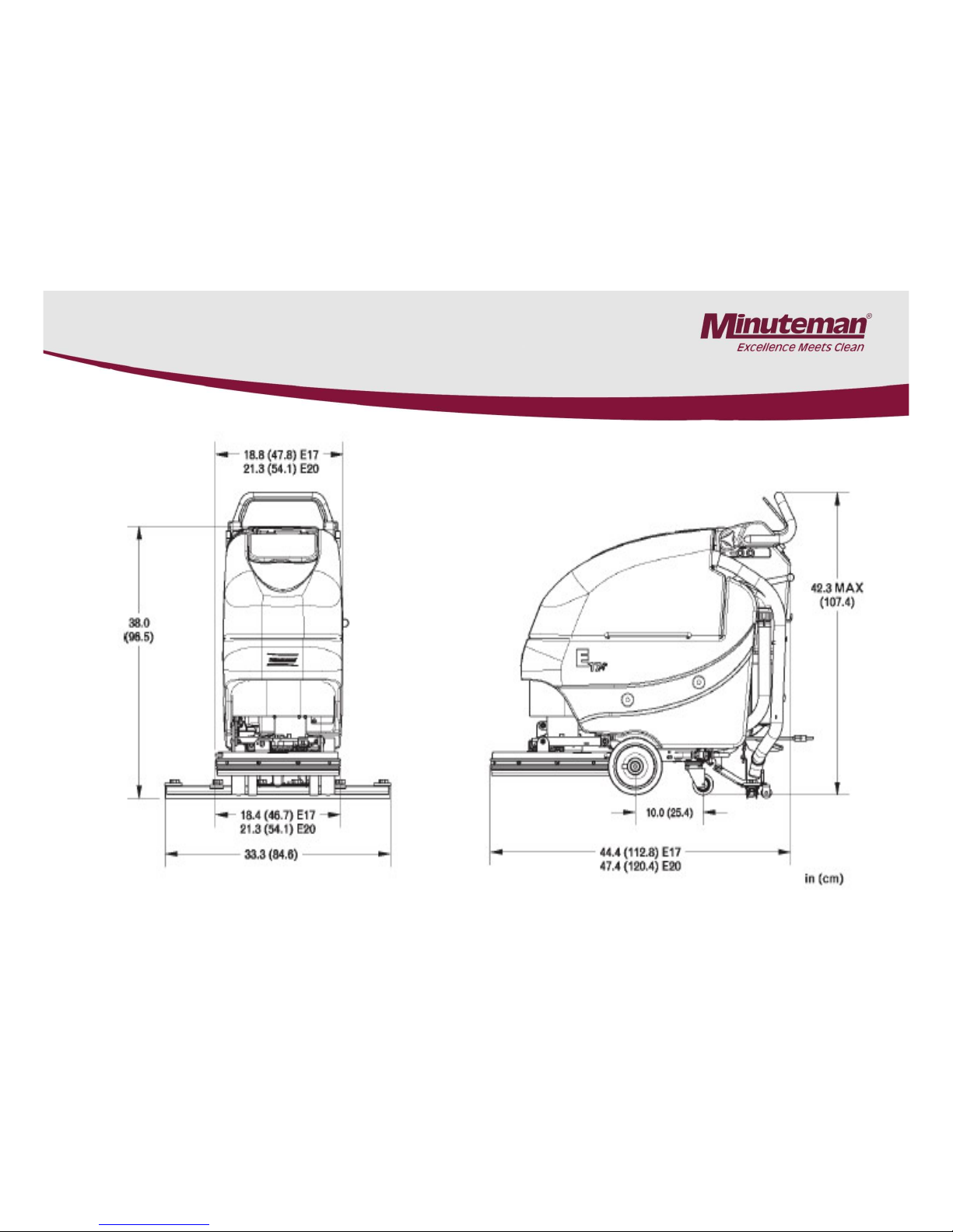
2.1 Dimensions E17BD & E20 BD
With a Straight Squeegee
Page 7
Page 8
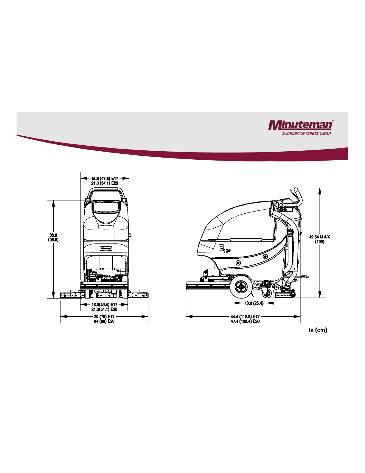
2.2 Dimensions (E17 & E20)
With Curved Squeegee
Page 8
Page 9

3. Maintenance Intervals
•Maintenance Intervals:
In a modular structure, the Minuteman System Maintenance determines the specific
technical proceedures to be preformed and sets the time interval between the two
maintenance cycles.
For each of the maintenance cycle, the replaceable parts are determined as well.
Further details described in the specific chapters.
•Minuteman System Maintenance K:
To be performed by the customer (in daily or weekly intervals) according to the maintenance
and care instructions as specified in the operating instructions.
The operator must be professionally instructed after delivery of the machine by selling
dealer.
•Minuteman System Maintenance I: (after every 125 hours of operation)
To be preformed an authorized Minuteman Service Center in accordance with the machinespecific system maintenance.
•Minuteman System Maintenance II: (after every 250 hours of operation)
To be preformed an authorized Minuteman Service Center in accordance with the machinespecific system maintenance.
•Minuteman System Maintenance S: (after every 500 hours of operation, safety check) To
be performed by an authorized Minuteman Service Center in accordance with the machinespecific system maintenance.
Page 9
Page 10

3.1 Minuteman System Maintenance K
Page 10
To be performed by the customer/user
Interval
Daily Weekly
Fill the clean water tank and mix the proper amount and type of cleaning solution. O
Charger the batteries. O
Check the brush head, Clean if needed with a damp cloth. Do not get water inside
the motor. O
Check the squeegee, clean if needed O
Check the lid gasket on the recovery tank. O
Empty and flush the recovery tank with clean water. O
Clean the filter/float inside the recovery tank. O
Check the water levels of all the batteries. Add distilled water, if needed. Do not
over fill. O
Check the pads and brushes for wear. Replace if needed. O
Check the squeegee hose for clogs, damage and wear. Replace if needed O
Check the squeegee rubbers for cuts and wear. Flip the blade(s) over or replace. O
Check the solution filter. Clean if needed. O
Flush the clean water solution tank with warm water. O
Test all the functions of the machine. O
Page 11
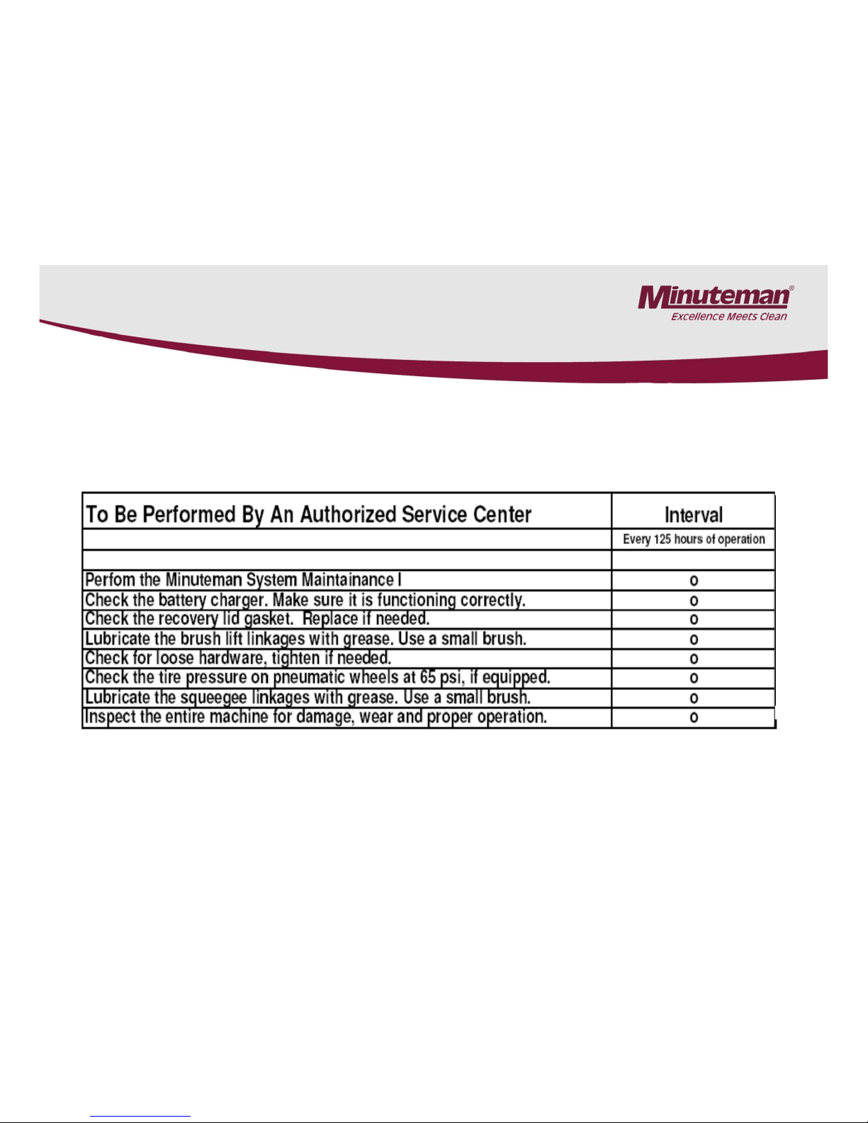
3.2 Minuteman System Maintenance I
Page 11
Page 12
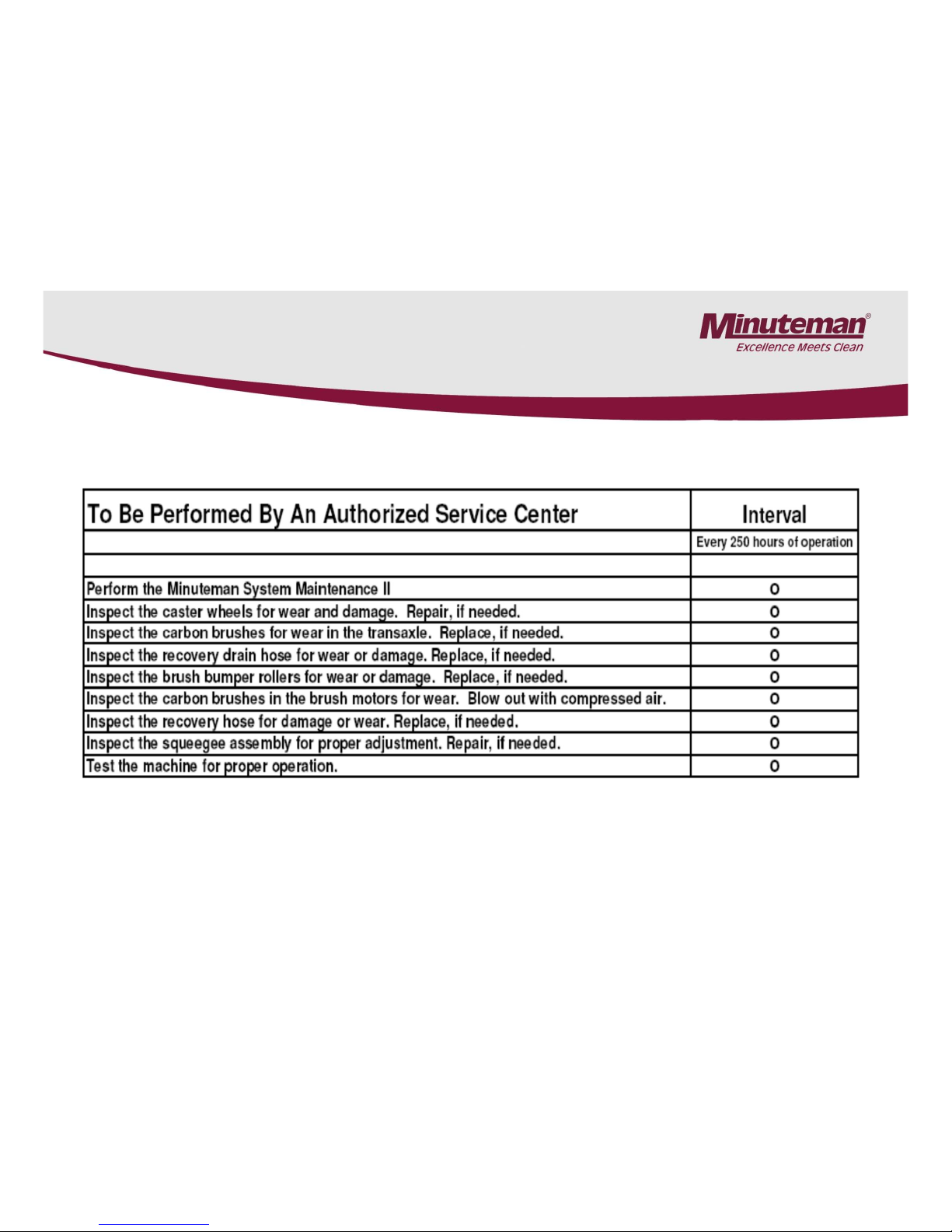
3.3 Minuteman System Maintenance II
Page 12
Page 13
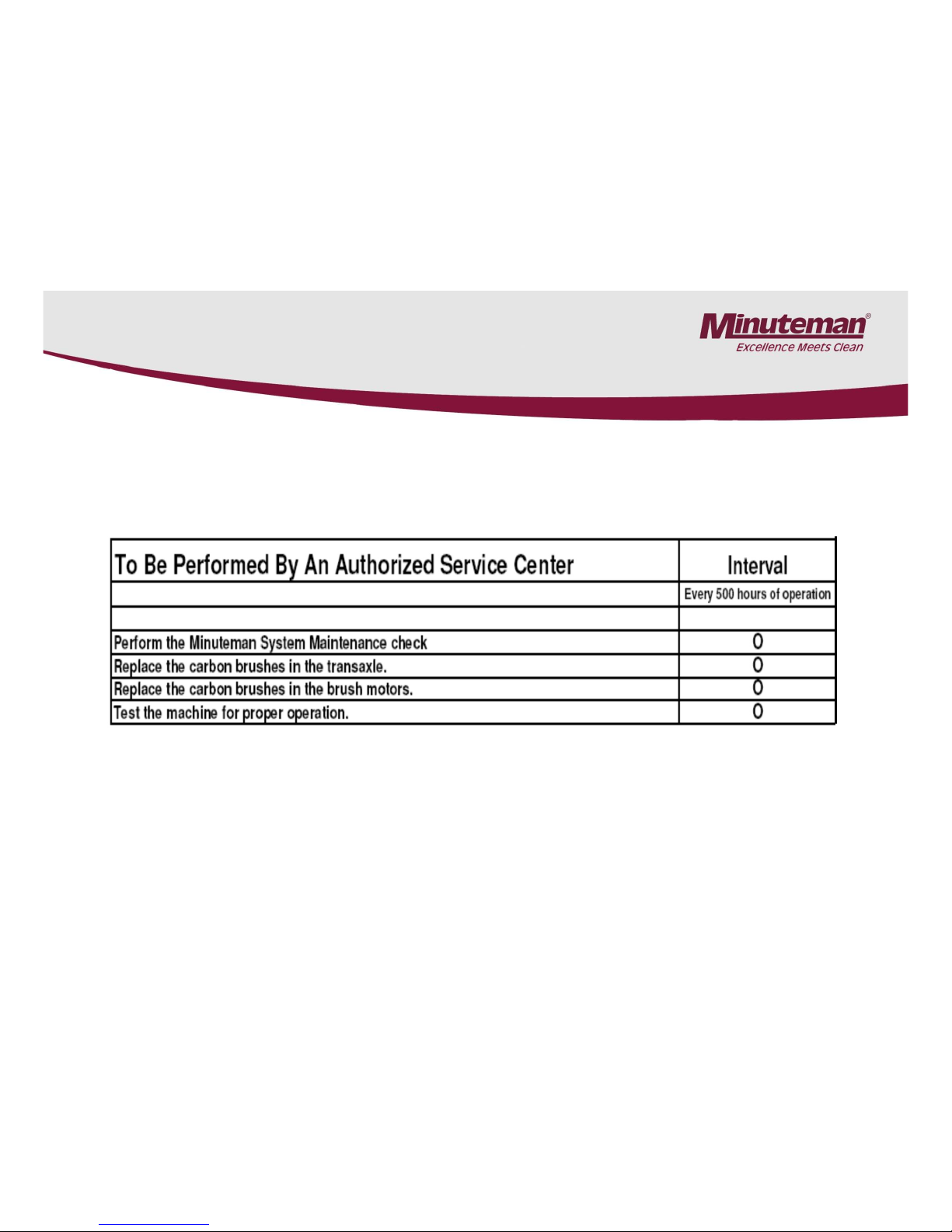
3.4 Minuteman System Maintenance S
Page 13
Page 14
4. Batteries & Wiring
•Battery Compartment
•The battery compartment is located under the
recovery tank. The battery compartment can be
accessed for servicing and maintenance by tilting the
recovery tank. Make sure the recovery tank is has
been drained before tilting.
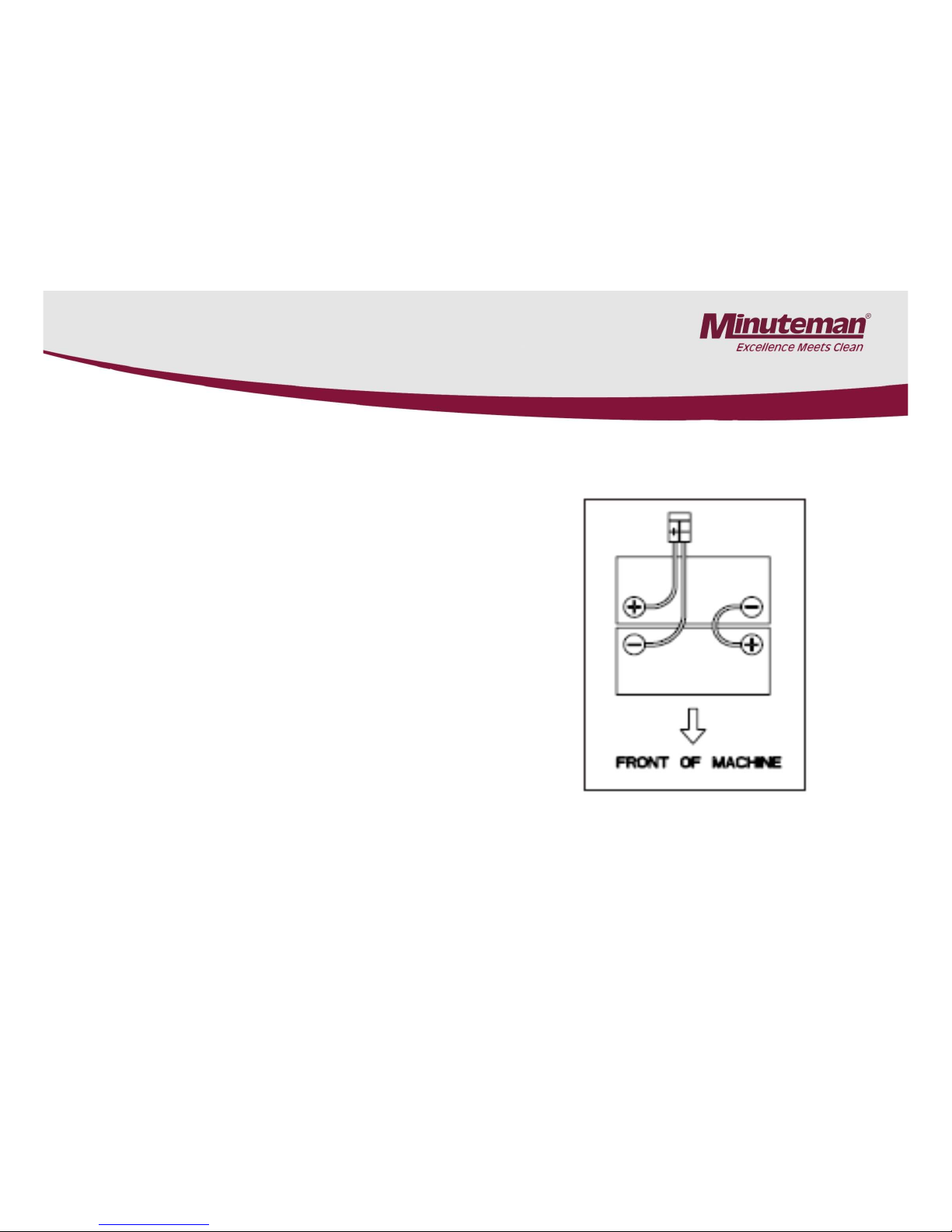
•The battery compartment contains two 12 volt
batteries connected in series.
•Connect the batteries according the battery wiring
diagram to the right.
•The recommended batteries are two 12 volt, 115 Ah
deep cycle battery part number 956712 for the Wet
Lead Acid type or 12 volt 100Ah AGM Maintenance
Free is part number 956100. Do not use Automotive
or Marine type batteries.
•When changing the type of battery (going to Gel from
Wet Lead Acid or visa versa) the battery charger will
need to be programmed accordingly. See Section 8.1
on Programming the Charger.
Page 14
Page 15
5. Recovery Float
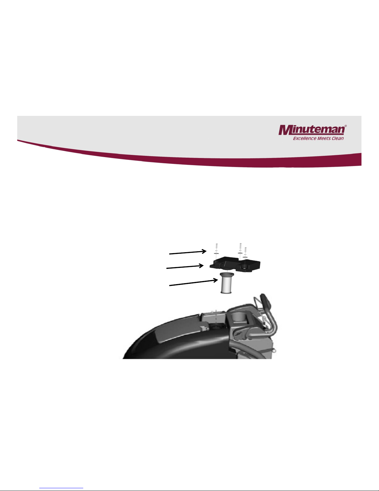
•The Recovery Float and Filter is located inside of the tank,
•The filter should be checked after each use and cleaned if needed.
•Remove the three screws and the cover, to access screen float for more extensive cleaning.
•Failure to do so will reduce the vacuum performance of the machine.
•Using the machine without it in place or picking up dry material will damage the vacuum
motor.
3 screws
cover
screen/float
Page 15
Page 16

Regularly scheduled lubrication of certain machine parts should
be performed to insure trouble-free
operation of the machine. Apply a generous amount of grease
into the fittings on the machine until grease
seeps out around the bearings. Wipe excessive grease off with
a towel.
The grease points are listed below:
1. Rear squeegee caster wheel axle (2)
2. Rear squeegee caster swivel (2)
Apply lubricant to:
1. The rear squeegee pivot points
2. The scrub deck linkages.
6. Lubrication
Page 16
Page 17
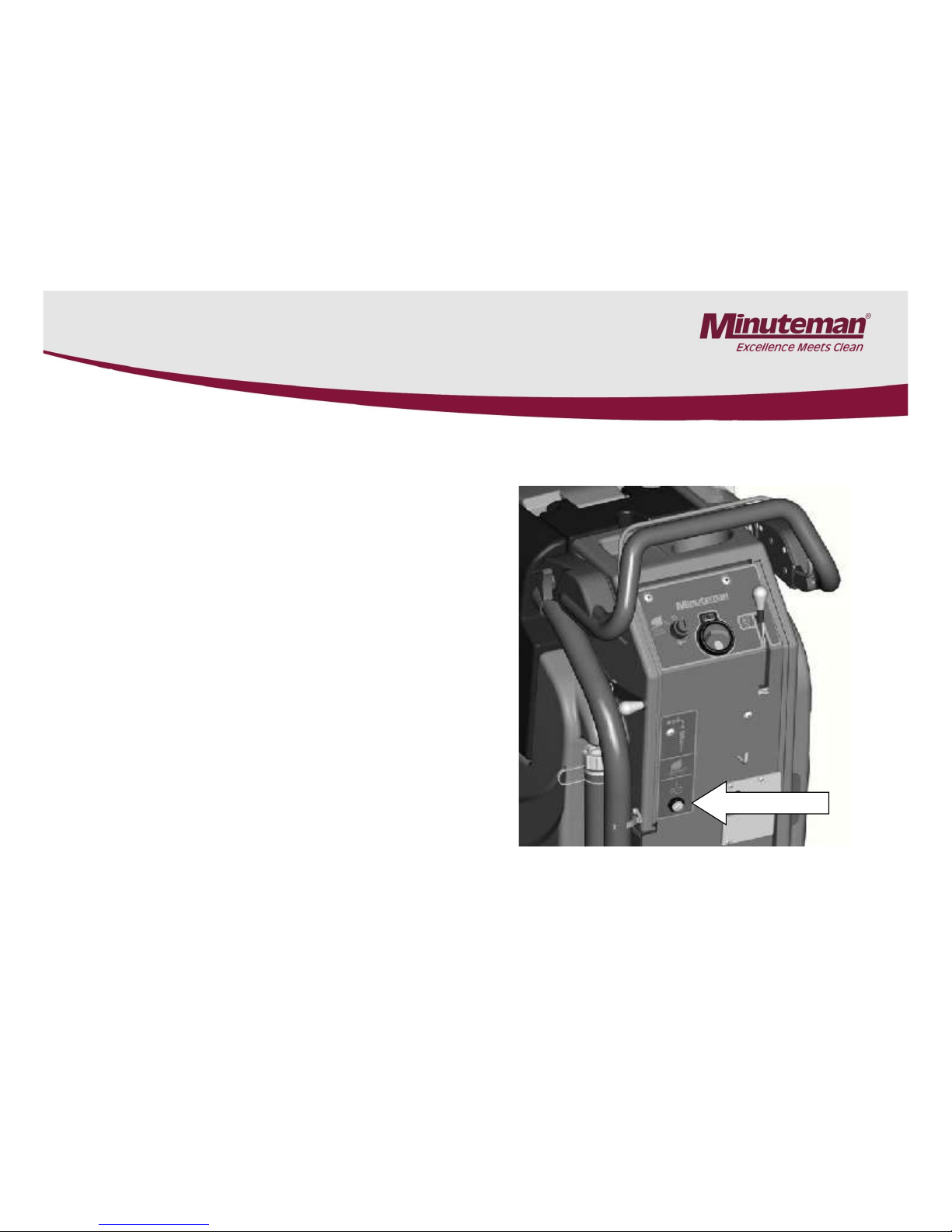
7. Charging Indicator (Version 1)
Charge Indicator
•The indicator will light during the
charging process.
•The red light indicates, the
batteries need a full charge.
•The yellow light indicates, the
batteries have received 80% of
their charge.
•The green light indicates, the
batteries are fully charged.
•The red light is flashing, indicates
the charger has detected a fault in
the batteries. (See Section 8.6)
Applies to the 957760 and 957761
chargers only.
Page 17
Page 18
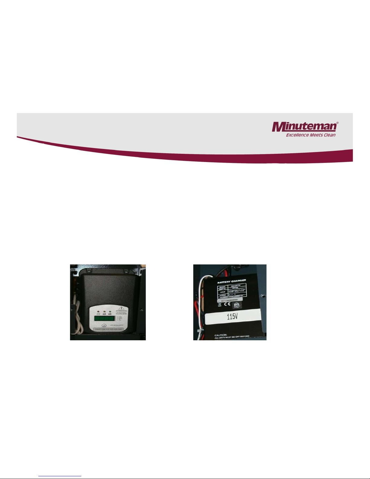
8. On Board Chargers (Version 1 and 2)
•The Minuteman on board chargers are capable of being programmed to charge lead acid
wet or gel type maintenance free batteries.
•The on board charger has a variety of other programming settings.
•Use caution when making changes. Incorrect settings may cause the charger to
malfunction and or damage the batteries.
•The 957745 charger (on left) has a series of dip switches located under the front decal that
can be used to change the settings.
•The 957760 and 957761 chargers (on right) has a accessible rotary switch at the bottom of
the charger.
957745 Charger 957760 & 957761 Chargers
Page 18
Page 19

8.1 Programming the 957745 Charger
1. Remove the large rear metal cover on rear the machine.
2. Locate the battery charger.
3. To access the Dip Switches, carefully peal the decal back on the front of the
charger. Start at the bottom left side and peal up. (Removing the plastic charger
cover is not necessary.) Use caution not to damage the decal.
4. There is a series of eight Dip Switches located under the decal.
5. Each switch is numbered 1 through 8.
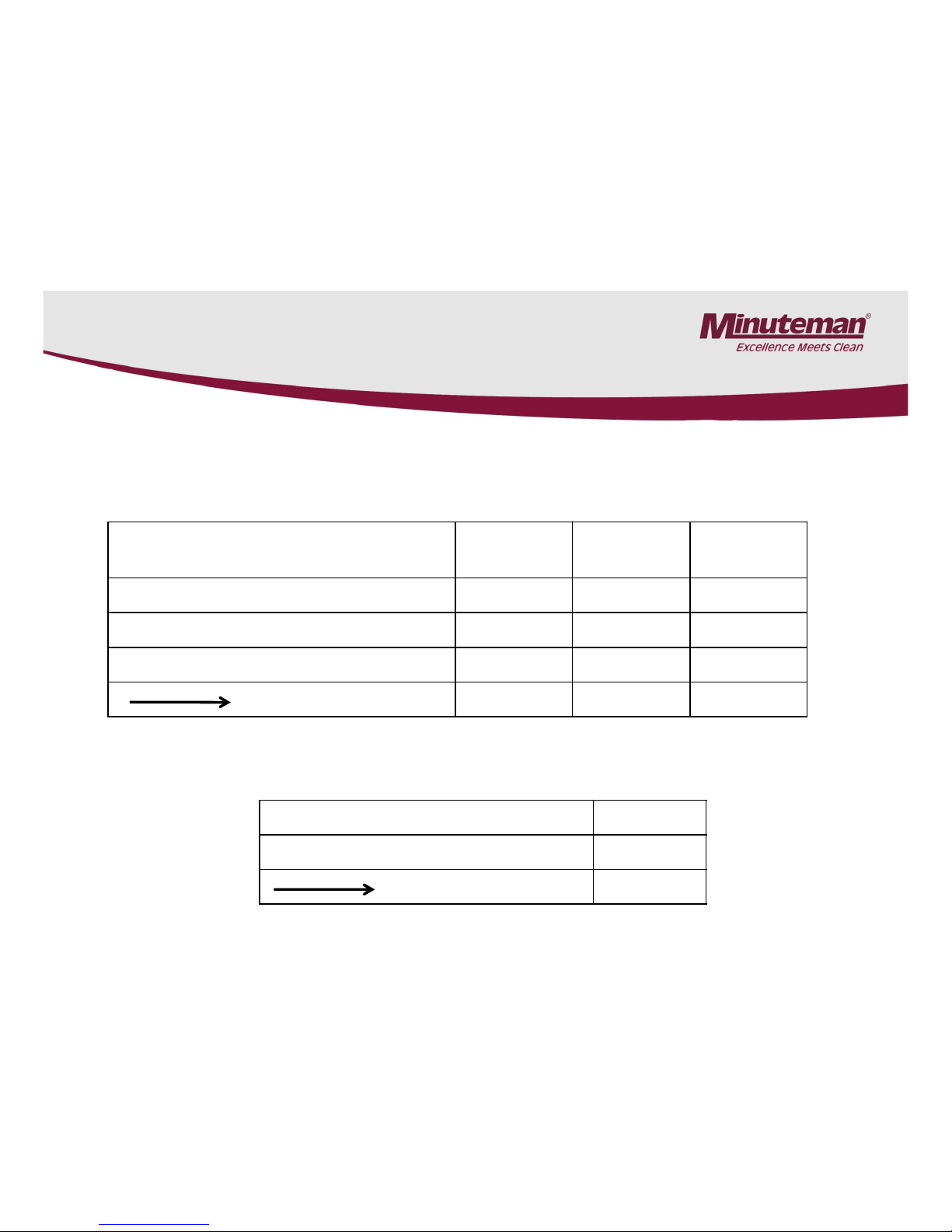
Dip Switches 1 to 4 are for setting the type of battery.
Type of Battery Switch 1 Switch 2 Switch 3 Switch 4
Lead Acid Wet Batteries ON ON OFF ON
AGM ON OFF OFF ON
Gel and Maintenance Free ON OFF OFF ON
Page 19
Page 20
Current (Amperage Output) Switch 5 Switch 6 Switch 7
4 AMPS ON ON NA
8 AMPS OFF ON NA
10 AMPS ON OFF NA
12 AMPS OFF OFF ON
The dip Switches 5,6 and 7 are for selecting the amperage output of the
charger. Use the 12 amp. setting only. * Note: The dip switch # 7 does not
have any function at this time.
Dip Switch 8 is to select the output voltage, either 12 or 24 volt. Use the
24 volt setting only.
Voltage Output Switch 8
12 Volts ON
24 Volts OFF
8.2 Charger Settings (957745)
Page 20
Page 21

8.3 Battery Charger Trouble Shooting
Version 1 and 2 Chargers
1. Does the battery charger turn on when plugged into the A.C. outlet?
2. Can you hear the cooling fan turn on? If not, check the A.C. outlet for
power.
3. Try a different outlet, if needed.
4. If it still doesn’t turn on, inspect the A.C. cord. Repair if needed.
5. Inspect the A.C. cord.
6. If the A.C. cord is Ok, check to see if the battery connector has been
plugged in to the machine’s connector.
6. Inspect the battery cables. Make sure they are clean and tight.
7. Test the voltage of the batteries; it must be above two volts minimum, before
the charger will turn on.
8. If everything above checks OK, and the charger still doesn’t turn on or
doesn’t have any output, replace the battery charger.
Trouble Shooting
Page 21
Page 22

8.3 Battery Charger Trouble Shooting
The Charger Turns On (957745 Charger)
1. If the charger appears to turn on, remove the rear metal cover on the rear of the machine.
2. The charger’s display should be lighted, when plugged in the A.C. outlet. If not, replace the
charger.
3. Check for errors on the chargers display (957745 only).
4. Press the number 5 on the charger decal (957745 only).
5. This will display different pieces of information about the charging process such as errors
(957745 only). (see error list), battery voltage, output amperage, hours of charging and
estimated amp hour of battery and wattage.
6. The voltage and amperage output should start to climb after a few minutes of starting the
charger, unless batteries are still hot from charging. If not, replace the charger.
The Charger Turns On (957760 & 957761 Chargers)
1. Check for errors on the charging indicator on the rear of the machine.
See section 8.6 “Battery Charger Error Codes”.
2. Inspect the A.C. power cord and plug for damage.
3. Test the outlet for A.C. power.
4. If no errors are displayed on the LED indicator. Test the output of the charger. The battery voltage
and output amperage should start to rise within a few minutes of starting up the charger.
5. Once the voltage reaches 28.8 volts the amperage should decreases until the amperage reaches
about 3.5 amps.
Note: The charger will not restart of the battery voltage is to high from being charged recently.
Allow time for batteries to cool, before attempting to re-start the charger.
Page 22
Page 23

8.3 Battery Charger Trouble Shooting
Page 23
How the smart chargers work
The charger is programmable for wet, gel and AGM battery types.
Phase one: The charger is designed to put full output of 10 to 12 amps until the battery voltage reaches
28.8 volts for the first phase (red LED), otherwise it will time out. The maximum time limit for wet
batteries is 12 hours for setting 1 and 15 hours for setting 2. Gel batteries have a 11 hour limit for the
first phase.
Note: The first phase is when heavy and prolonged gassing can occur, if one or more cells are not
reaching adequate voltage in the designated time programmed into the charger.
Phase two: The 28.8 volts is maintained (yellow LED) until the output current decreases to 3.5 -4.7
amps for wet batteries, then voltage should rise until it reaches 32.4 volts. The green LED (full charge)
should light.
Wet batteries have a time limit of 5 hours for phase two.
Gel batteries will receive 28.8 volts until the chargers output reaches .5 amps (green LED, full charge).
Maintenance Charge: Once the batteries reach the full charge status, the charger will maintain
(float/maintenance charge) the batteries at 26.4 volts for wet batteries and 27.3 volts for gel batteries,
provided the charger is plugged into the A.C. outlet. Note: This will prevent the batteries from
discharging, if the machine is not used for long periods of time.
Page 24

•The greater the variation between cells in any one battery, the greater loss of running time.
A battery with variations of .040 or greater should be replaced.
•The variation of .020 is considered normal.
•Specific Gravity Readings are as follows:
1.280 and above 100% charged cell
1.235 to 1.240 = 75% charged cell
1.190 to 1.195 = 50% charged cell
1.150 to 1.175 = 25% charged cell
1.140 or less = 0% charged cell
•Load test the batteries with a battery load tester.
•The voltage difference should be less that 1 volt, when testing under load.
Any battery that has 1 or more volt(s) less than the other should be replaced
.
8.3 Charger Trouble Shooting
(Excessive Gassing or Water Consumption in Batteries)
Page 24
1. If the charger appears to be charging and excessive gassing or water
consumption had been or is occurring in the batteries.
2. Check the following:
3. A. Have the batteries been maintained on a consistent basis? Failure to maintain batteries will
shorten their life and reduce their performance.
B. Test the batteries with a hydrometer. The batteries should be fully charged and cooled for 2
hours after charging, before testing. Top the batteries off with distilled water prior to charging, if
needed. Do not over fill.
C. Compare the cell readings of all the cells in each battery.
Page 25

Codes that could be displayed on the charger are as follows:
“Bat” = The batteries are not detected. Voltage is below 2 volts,
The polarity could be reversed or batteries disconnected.
“Acd” = the charger programming set for wet lead acid batteries. (not an error)
“Gel” = charger programming set for gel batteries (not an error)
“E01” = maximum battery voltage has been reached.
“E02” = charger is overheating, faulty cooling fan or the cooling air to charger is obstructed.
“E03” = the batteries have exceeded the normal charge time. Possible battery sulfation has
occurred. Cycle the batteries several times (charge and discharge).
“SCt” = safety timer operation. This normally occurs after any allotted phase time period has
expired.
“Srt” = internal short circuit in charger. Replace the charger.
8.4 Battery Charger Error Codes
957745 Chargers Only
Page 25
Page 26

8.5 Programming the Battery Charger
(957760 & 957761 only)
1. Remove the rear metal panel on the machine.
2. Remove the 957761 charger completely from the machine.
3. Locate the rubber plug on the bottom right side of the charger.
4. Remove the rubber plug.
5. Locate the selector switch.
6. Use a small flat tip screw driver to turn the red indicator to the desired
setting. See the chart below.
7. Replace the rubber plug and install charger into the machine.
Switch Position Battery Type
1
All Wet Flooded Lead Acid 95 to 115 AH (Group 27)
1 AGM Maintenance Free Part # 956100 (95 AH) (OEM only)
2
All Wet Flooded Lead Acid 130 to 140 AH (Group 31)
2 AGM Maintenance Free Part # 956135 (135 AH) (OEM only)
3
GEL/AGM (NON OEM) 135 amp hr
4
GEL/AGM (NON OEM) 95 to 100 AH and Trojan AGM 102 (AH) hr. Minuteman Part # 956157
Note: These are the only settings available. For non OEM batteries, please contact supplier for the charging
requirements. Select from the list above. The remaining settings do not have any additional functions.
Bottom view with plug Bottom with plug removed Selector Switch close up
Instructions
Page 26
Page 27

Faults are displayed red LED on the battery charge indicator.
RED LED BLINKS ONCE AND REPEATS: OUTPUT CONNECTION ERROR.
1. Check for loose or corroded connections between the charger and the batteries.
2. The output may be shorted due to improper connection to the batteries or pinched wires.
3. The output may be connected in reverse polarity to the batteries.
4. The battery voltage may be too high (higher than a 24V battery pack).
This condition can also occur, if the charger is restarted immediately after charging.
Allow batteries to cool down before restarting the charger.
Note: The charger is not damaged by any of these problems except when connected to
Batteries totaling 48 volts or more.
RED LED BLINKS TWICE: CHARGER HAS TIMED-OUT
The charging progress timer has elapsed before charging was complete and charger has
stopped charging. Possible causes:
1. The batteries are extremely discharged – Unplug the AC cord connection for 30 seconds
minimum. Let batteries cool down if hot. Reconnect the AC cord to start a new charge cycle.
2. The electrolyte is low in one or more cells – Correct by adding distilled water.
3. Batteries are weak, old, or have one or more bad cells. Batteries will still charge but capacity
will be reduced. Replace the batteries, if needed.
4. If batteries are new, the batteries may need to be conditioned by charging and discharging them.
Some batteries may need to be cycled several times in order to condition them to their full potential.
8.6 Battery Charger Error Codes
957760 & 957761 Chargers Only
Page 27
Page 28

Page 28
Faults are displayed red LED on the battery charge indicator cont.
All Three lights blink at the same time
1. Charger is restarting
2. Charger is unable to put full output to the batteries
3. Possible loose or poor connections. Check all connections.
4. Batteries may need to be conditioned by charging and discharging them.
Some batteries may need to be cycled several times in order to condition
them to their full potential.
8.6 Battery Charger Fault Codes Cont.
957760 & 957761 Chargers Only
Page 29

8.7 Prime Chargers
• Machines built after serial number 18060266 will be equipped the Prime Chargers
• Prime chargers are pre-programmed at the factory for specific battery types and are not
reprogrammable in the field.
• The maximum D.C. output is 12 amps.
• The current (amps) will decrease as voltage climbs.
• Machines built with the earlier style chargers can not be upgraded to the Prime charger
Prime Charger
Indicator Version 1
Prime Charger
Indicator Version 2
Page 29
Page 30

8.8 Prime Charge Status Indicator
• The charger includes one (1) local LED that can display three (3) colors to indicate charger status and fault
information (see Figure 5-1). The functionality of the LED is outlined below. If an optional remote LED is
being used, it will provide the same functionality.
• Amber (Charge Status) Indicates charge cycle status. See Figure 13-1 for descriptions of the possible
states.
• Green (Charge Status) Indicates when a charge cycle completes successfully, when an extended
Balance/Equalize charge cycle phase is active, or when a post-charge phase is active.
See Figure 13-1
for descriptions of the possible states.
• Red (Fault) Indicates when a charger or battery
fault has occurred. See the FAULTS section.
Page 30
Page 31

8.9 Prime Charger Indicator
(Fault Codes)
Removing AC power from the
charger always clears a fault.
If the charger was factoryconfigured for off-board use,
disconnecting the charger from
the battery pack also clears a
fault.
If a fault cannot be cleared after
taking appropriate corrective
action, contact your dealer for
troubleshooting and/or service.
Page 31
Page 32

9. Battery and Error Code Indicator
Traction Drive Models only
•The indicator will display the charge status during machines operation. The
indicator uses ten LEDS. 1 to 10 LEDS may be illuminated at any given time.
10 being a fully charged battery pack. 1 LED would be a discharged battery
pack.
•The indicator will also will display errors by rapidly flashing 1 to 10 LEDS.
See the following references for the type of error that it has detected.
Page 32
Page 33

The battery needs charging or there is a bad connection to the battery.
Check the connections to the battery. If the connections are good, try
charging the battery.
1 Bar = Low Battery Voltage
2 Bars = Traction Motor Disconnected
There is a bad connection to the Traction motor. Check all
connections between the motor and the control system.
3 Bars = Traction Drive Motor Shorted
There is a short in the Traction Drive circuit. Possible short in the drive
motor or harness.
9.1 E17TD & E20TD Error Codes
Page 33
Page 34

4 Bars = Battery Lockout
The traction drive controller has shut down because of low battery
voltage. Charge the batteries. If problem still exists: Test batteries and
check all battery connections.
5 Bars = Not Used
6 Bars = Not Used
9.1 E17TD & E20TD Error Codes
Page 34
Page 35

7 Bars = Throttle Trip
A throttle trip is indicated. The potentiometer is not detected in circuit or
incorrect resistance value seen by I-drive controller. Test the 5K
potentiometer circuit.
8 Bars = Control System Trip
A control system trip is indicated. Make sure that all connections are secure.
This can also occur if the key switch is turned on and off rapidly
9 Bars = Not Used
9.1 E17TD & E20TD Error Codes
Page 35
Page 36

9.1 E17TD & E20TD Error Codes
10 Bars = High Battery Voltage
An excessive voltage has been applied to the control system. connections. This
is usually caused by a poor battery connection. Check the battery connections.
No Bars = Control System in Sleep Mode
The control system has entered sleep mode. Switch the control system off
and then on again.
Page 36
Page 37

Ripple = Throttle Displaced
Looks similar to the start up above. Repeats. The drive switch has been
activated while powering up the machine. Place the throttle in the neutral
position and turn the control system on and off again. Possibly the drive
switch is stuck on.
Start UP
This is an initialization message. Repeats until system is verified to be functional.
Occurs during the initial startup of the machine, if it hasn’t been powered up for a
period of time. Note: This is not a fault or error.
9.1 E17TD & E20TD Error Codes
Page 37
Page 38

10. Trouble Shooting Brush Motor
Controller (Sport Models only)
1. The I-drive brush motor controller works similar to the traction drive I-Drive controllers, except for
is rated for 180 amps.
2. The sport key switch changes the speed of the brush motor speed from 200 rpms to 400 rpms.
3. The potentiometer for the brush controller is mounted inside the electrical box and is always set to
the full clockwise position. Turning it counter clockwise will slow both speeds of the brush motor.
Turning it full counter clockwise will shut the brush motor off.
4. When brush motor current reaches 50 to 52 amps, the motor will be throttled back to 35 amps to
prevent from over heating over loading. Try dispensing more water and reduce pad pressure by
removing the weighted plate, if needed to prevent controller from over heating and shutting down.
(circuit breaker has not tripped)
5. The brush controller has a thermo shut off built in it, and it will shut down the brush motor when
the controller overheats. It will rest automatically.
6. The brush motor can be activated in both the unload and scrubbing modes.
7. When using the unload feature the key switch must be held in the counter-clockwise position for at
lease 5 seconds so that the controller has time to boot up.
8. Testing Potentiometer - See page 59.
9. If the unload feature works, but the brush motor will not run in the scrubbing mode. Check the
brush switch in the handle and the switch in the front of the machine. See below
Page 38
Page 39

11. Squeegee (Curved)
11.
Page 39
Page 40

11. Squeegee (Curved)
11.1
Page 40
Page 41

11. Squeegee Caster Adjustment
(Curved)
11.2
Clearance between support roller and floor with unfolded sealing strip (Factory
presetting): 3 mm ±0.5 (Fig. 5/2).
Place additional 1mm spacers (pos. 15, Fig. 5/3) between the angle and the fixed roller
housing (pos. 7, Fig. 5/3) to increase clearance or remove existing 1mm spacer from
between the angle and the fixed roller housing in order to reduce the clearance. Re-insert
the spacers removed from between the angle and the fixed roller housing again above
the fixed roller housing to allow complete tightening of the screws.
3mm ±0.5
0.118 in
± .02
Page 41
Page 42

Washers may be
rearranged to change the
height of the squeegee
caster.
Note: When adjusting the wheel height, there should always be 5
washers on each wheel assembly in order fully tighten bolts. Move
washers from the top to the bottom of the bracket or visa versa when
making adjustments. See following page.
11.3 Curved Squeegees Only
11. Squeegee Caster Adjustment
(Curved)
Page 42
Page 43

11.4 Curved Squeegees Only
•Possible squeegee caster
washer combinations.
11. Squeegee Caster Adjustment
(Curved)
Page 43
Page 44

1. Always keep the water levels above the plates
2. Fill the batteries with distilled water only. Tap water can cause an
excessive build up of minerals and reduce the chemical reaction of
the batteries. This will shortening the life and performance of the
batteries.
3. Use appropriate filling devices when filling the batteries. Do not
use a garden hose or metal containers. Flooding the batteries can
flush the electrolyte out of the battery and shorten its life.
4. Fill cells 3/8 to 1/2 of an inch above the separators. Do not fill
above the fill marker of the batteries. Over filling can cause the
electrolyte to percolate out onto the case while charging.
12. Maintaining Wet Batteries
Page 44
Page 45

5. Check water level daily. Fill, if needed.
6. Keep all the battery cable connections tight.
7. Keep all the battery posts and cables clean. Clean the battery cases
with a mixture of baking soda and water solution or commercial spray
that neutralizes the acid. Spray the cases with a water displacement
chemical or a silicone. This will help break the flow of current across
the case and increases the life of the battery.
Note: The electrolyte on the surface of the case can cause:
A. The batteries to discharge faster even while sitting and have a shorter
run time.
B. The battery charger to stay on for extended periods. Thus causing an
over charge condition and shortening the life of the batteries.
12. Maintaining Wet Batteries
Page 45
Page 46

13. Load Testing The Batteries
• Load test battery with an automotive type load tester. This test puts
an ampere load on the batteries and measures the voltage at the same
time.
• If voltage drops too low on the meter, this would indicate that the
batteries are weak or discharged.
• A fully charged good battery should test in the good or green range of
the meter. Load testing can identify dead cells, broken or
disconnected plates, weak cells and charge status.
• This is good test, however it can only detect these types of failures.
• Most load testers require putting a load on the batteries for 10
seconds.
• Load testing may not detect all short run time issues.
Page 46
Page 47

14. Hydrometer Testing Batteries
•Hydrometer testing can used to measure the specific gravity of deep cycle
batteries. This allows you to detect weak cells, which are causing loss of running
time. It can only detect this type problem. The hydrometer should have specific
gravity markings such as 1.265, 1.250, 1.225, and so on.
•Hydrometers with the four balls are not accurate enough for this test are not
recommended.
•Fully charged batteries should read 1.265 and will decrease as batteries are
discharged until they reach 1.120. This test should be done when batteries are
charged and cooled. Allow one hour or more to cool. It can also be done after
batteries are partially discharged, if they are allowed to cool. However, you will
not be able to detect the full capacity of the battery.
•Note: Maintenance Free batteries can not be tested with a hydrometer.
Do not attempt to remove caps or covers. This will destroy the battery.
Page 47
Page 48

14. Hydrometer Testing The Batteries
• To do an accurate test, the battery water level must be high enough to
extract enough electrolyte to fill hydrometer so that the float floats.
Water should be added prior to charging in order for let the electrolyte
to mix.
• The greater the variation between cells readings, the greater the loss
of run time. For example, if the readings are 1.265, 1.265 and 1.225 in
one 6 volt battery. The low cell would be considered weak and greatly
reduce the performance of the battery or shorter run time. This
battery would have a point 40 variation. Batteries that have weakened
cells in most cases it can still be used as long they continue provide
adequate run time. A battery with a point 40 variation or more should
be determined defective.
•Hydrometer Testing
Page 48
Page 49

14. Hydrometer Testing The Batteries
• Minuteman batteries are rated for about 500 charge cycles. The life of
the battery will be greatly dependent by the maintenance they receive.
• Every time the batteries are charged it uses one cycle.
• The specific gravity will reflect the percentage of charge remaining in
the battery.
• 100% charge = 1.265 or higher Specific Gravity
• 75 % charge = 1.225 Specific Gravity
• 50 % charge = 1.190 Specific Gravity
• 25 % charge = 1.120 Specific Gravity
• Note : AGM & Gel maintenance free batteries can not be tested with
the hydrometer. Do not attempt to open cell covers or caps.
• Doing so will destroy the battery.
Page 49
Page 50

15. Transporting The Machine
When transporting the machines on a trailer or truck always:
• Tie down the machine securely.
• Lower the brush head assembly completely to the floor.
• Turn the machine off.
• Failure to do the above may result in damage to the machine.
Page 50
Page 51

16. Key Switch
Switch Off
Switch On
Switch Unload
•The key switch has 8 terminals. Below shows the three different switch
functions. The black bars indicate the internal connection made by the
switch in each position.
Page 51
Page 52

17.1 Solution Filter (Version 1)
17.1
Page 52
Page 53

17.2 Solution Filter (Version 2)
1. The solution filter is located under the machine.
2. The filter can be cleaned by unscrewing cap.
3. Drain solution tank before cleaning filter.
Filter Location New Style Solution Filter
Page 53
Page 54

B-
From Battery
B+
From Battery
B+
Controlled
B-
Controlled
25 Volts
Digital Volt Meter
18. Testing the Main Power Relay on the E17, E20 and
E26ECO
Note: Measure the voltage across the B+
and the B- coil terminals with the wires
attached and the key switch turned on.
It should be about 24 volts.
Diode
Page 54
Page 55

B-
From Battery
B+
From Battery
B+
Controlled
B-
Controlled
25 Volts
Digital Volt Meter
18. Testing the Main Power Relay on the E17, E20 and
E26ECO
Note: Measure the voltage from a battery negative
source to the B+ terminal of the main relay’s coil to
determined of the B+ is being supplied to the coil.
It should be 24 volts.
+ -
-
+
Batteries
OR
Page 55
Page 56

B-
From Battery
B+
From Battery
B+
Controlled
B-
Controlled
25 Volts
Digital Volt Meter
18. Testing the Main Power Relay on the E17, E20 and
E26ECO
Note: Measure the voltage from the battery positive
source to the B- terminal of the main relay’s coil to
determined of the B- is being supplied to the coil.
It should be 24 volts.
+ -
-
+
Batteries
OR
Page 56
Page 57

B-
From Battery
B+
From Battery
B+
Controlled
B-
Controlled
25.5 volts
Digital Volt
Meter
18. Testing the Main Power Relay on the E17, E20 and
E26ECO
Note: Measure the
voltage across the
battery side across the
B+ & B- terminals when
the machine is under
load.
Page 57
Page 58

B-
From Battery
B+
From Battery
B+
Controlled
B-
Controlled
+-
22.4
volts
Volt Meter
18. Testing the Main Power Relay on the E17, E20 and
E26ECO
Note: The voltage
should be exactly the
same as incoming
battery side when
the machine turned
on and is under load
(motors are running).
The relay is defective
Page 58
Page 59

19. Trouble Shooting the Drive Circuit
Testing the Potentiometer and Drive Switch circuit.
The potentiometer, drive switch and forward switch circuit can be tested all together from the 14
pin harness connector at the I-Drive controller (traction drive models only).
•.Remove the rear panel of the machine.
•Locate the I-Drive controller (silver box)
•Disconnect the 14 pin electrical connector on the I-Drive
•Use an ohm meter (analog for best results) and measure the resistance between the
black/orange and black/white wires. It should be approximately 5K (4.7) ohms.
If not see “Testing the Potentiometer”.
•Test the resistance between the black/pink and black/orange wires. Turn the shaft of the
potentiometer while measuring. The forward and reverse switch will need to be in the forward or
reverse position (test in both positions). Activate the drive lever. The resistance should vary from
5K to Inf. The resistance should change smoothly, If not see “Testing the Potentiometer”.
Testing the Potentiometer
•Disconnect the potentiometer from the circuit.
•With a ohm meter, measure the resistance across the black/orange wire and the black/white
wire. The resistance should be 5K (about 4.7 K ohms). If not replace potentiometer.
•Test the resistance between the black/pink and the black/white wire. (Use an analog meter for
best results) Turn the shaft of the potentiometer while measuring. The resistance should vary
from 5K to Inf. The resistance should change smoothly, if not replace the potentiometer.
•Test the resistance between the black/pink and the black/orange wire the wire. Turn the shaft of
the potentiometer while measuring. The resistance should vary from 5K to 0 (zero). The
resistance should change smoothly, if not replace the potentiometer.
Page 59
Page 60

Testing the Drive Switch.
•Remove the access plate on the right side of the drive handle. Test the
switch that is connected to the red and white wires coming from the main
harness. The blue and black connection should test open until the switch is
activated. It should close when it is activated. If it doesn’t replace the switch.
19.1 Trouble Shooting - Traction Drive Switch
Page 60
Page 61

19.2 Trouble Shooting –Vacuum Motor
The vacuum motor will not turn on Traction Drive models only.
1. Verify the vacuum switch is functioning correctly. The machine should not
move in reverse with the squeegee (vacuum on) in the down position.
When squeegee is raised, the machine should back up.
2. Remove the rear panel of the machine.
3. Measure the voltage across the coil (small) terminals of the vacuum
contactor (do not go to the battery for this test.) with squeegee/vacuum
switch activated and driving the machine forward.
4. The wires will need to be connected to terminal while doing test.
Note: Lift the drive wheels off the floor before doing test.
The voltage should be 20 to 24 volts. If not go to step 5.
If the 20 to 24 volts is present, test vacuum relay step # 8.
5. Remove the diode from the contactor and test with a multi-meter.
It should have continuity in one direction. Replace, if it shorted in both
directions.
Note: The diode should be wired with the silver band closest to the red
(positive) terminal when it is mounted to the relay terminals.
Page 61
+
Page 62

19.3 Trouble Shooting – Vacuum Relay
7. Testing the vacuum motor relay (all models)
1. Power up the machine.
2. With the vacuum switch and drive circuit
activated.
3. Test for voltage across the two large contact
terminals on the vacuum relay. It should
read 0 (zero) volts. When it is deactivated it
should measure 24+ volts.
4. If not replace the relay.
Page 62
6.
Retest for voltage across the vacuum
coil (small) terminals with the
squeegee switch and drive activated.
If the voltage is below the 18 volts,
replace the I-drive controller. If
voltage is above, continue testing the
vacuum relay in step 7.
Coil Terminals
Contact
Terminals
+
Page 63

19.4 Testing the Drive System Potentiometer
5 K
5K Fixed Value
Does not
change while
turning shaft
Fig. 1
5 K
5K to 0K
Variable
Resistance
Adjust shaft
while testing
Fig. 2
5 K
0 to 5K Variable
Resistance
Adjust shaft
while testing
Fig. 3
1. Disconnect the potentiometer from circuit
2. Use ohm meter (preferably an analog type) to measure the resistance across the
two outside terminals (Fig. 1). It should measure 5K (5,000 ohms +/- 20%)
3. Measure the resistance from the center terminal to each outside terminal.
Fig. 2 and Fig. 3) The resistance should show a smooth change while turning the
shaft on each.
Page 63
Page 64

20. Notes
Page 64
 Loading...