

Page 1

Owner's Manual
60
Page 2

The following are examples of symbols used to alert the user to
important information:
CAUTION
RISK OF ELECTRIC SHOCK
cm
CAUTION TO REDUCE THE RISK OF ELECTRIC SHOCK,
DO NOT REMOVE COVER (OR BACK)
NO USER SERVICEABLE PARTS INSIDE
REFER SERVICING T O THE F ACT OR Y
This symbol is intended to alert the user to the presence of uninsulated
c
m
dangerous voltage within the products enclosure that may be of suffi-
cient magnitude to constitute a risk of electric shock to persons.
This symbol is intended to alert the user to the presence of important
operating and maintenance (servicing) instructions in the literature accom-
panying the appliance.
WARNING Electrical Shock Hazard. The batteries contain HIGH
DO NOT OPEN
VOLTAGES. To reduce the risk of electrical shock, use
caution when handling the units.
SAFETY Save these instructions. This manual contains
INFORMATION important instructions that should be followed during
installation and maintenance of the UPS and batteries.
Minuteman Continuous Power Series UPS
1
Page 3

CONTENTS
SECTION 1. INTRODUCTION..........................................................................5
Why is the Minuteman Continuous Power Series UPS One of the Best? ..............5
How the Continuous Power Series Protects Your System.......................................8
About the Manual....................................................................................................9
SECTION 2. PREPARATION..........................................................................10
Unpacking the UPS...............................................................................................10
Overview of the UPS.............................................................................................11
SECTION 3. INSTALLATION..........................................................................14
Positioning the UPS..............................................................................................14
Connecting the Hardwired UPS.............................................................................15
Connecting the Plug and Play UPS.......................................................................24
Installing the Optional Transformer........................................................................25
Installing External Battery Packs...........................................................................32
Installing a Customer Supplied External DC Source.............................................34
Connecting Load Through Output Circuit Breaker Plate.......................................35
Interface Ports.......................................................................................................36
SECTION 4. OPERATION............................................................................38
Operation Mode and Configure Mode...................................................................38
Operation Mode....................................................................................................38
UPS Alerts.............................................................................................................40
LED Indicators.......................................................................................................41
Configure Mode.....................................................................................................43
Using Communication Interfaces and Rear Panel Controls...................................45
Using Options........................................................................................................46
SECTION 5. MAINTENANCE.........................................................................50
Preventive Maintenance........................................................................................50
Battery Life............................................................................................................50
Battery Recharging................................................................................................50
Storing the UPS.....................................................................................................50
Maintenance..........................................................................................................51
SECTION 6. SPECIFICATIONS.......................................................................52
Electrical Input.......................................................................................................52
Electrical Output....................................................................................................52
Internal Battery......................................................................................................52
Physical.................................................................................................................52
Model Specifications Table....................................................................................53
SECTION 7. TROUBLESHOOTING..................................................................54
SECTION 8. OBTAINING SERVICE.................................................................56
Page 4

INTRODUCTION
Congratulations! By purchasing Minuteman's Continuous Power Series
Uninterruptible Power System (UPS), you now own superior power
protection equipment. Your sensitive electrical equipment will be pro-
tected from virtually any problem associated with AC power. The Con-
tinuous Power Series UPS is designed to protect many types of electrical
equipment including midsized networks, work stations, file servers, Point-
of-Sale (POS) cash register systems, medical equipment, and telecom-
munications equipment while providing outstanding performance and
reliability.
WHY IS
DUAL CONVERSION ONLINE TECHNOLOGY
Dual conversion online technology makes the Continuous Power Series
a true online system that delivers excellent voltage regulation and an
extremely low input current distortion.
ADVANCED BATTERY MANAGEMENT
The Continuous Power Series has Minuteman's exclusive Advanced
Battery Management (ABM) feature that doubles battery life and
speeds up recharge time to give you maximum battery reliability.
SOPHISTICATED COMMUNICATION INTERFACE
The Continuous Power Series communication interface features a relay
interface port and an RS-232 port. Both ports allow the user to monitor
AC power conditions and the operational status of the UPS. The Con-
tinuous Power Series is also fully compatible with Network Manager II
UPS management software.
START-ON-BATTERY
The Continuous Power Series has a start-on-battery option which allows
you to start up your system via the internal battery in the event AC power
is not available.
THE CONTINUOUS POWER SERIES
UPS ONE OF
THE BEST
?
TWO-PHASE FLEXIBILITY
The Continuous Power Series two-phase models have simultaneous
multiple output voltages (120/208 or 120/240) which improves utility load
balance. This feature prevents overloading on a single line and enhances
overall system stability.
2
Page 5

Table 1-1. Continuous Power Series Standard Models
MODELS* STYLE
1
INPUT /
OUTPUT
CONNECTION
KVA
RATING
VOLT
VA C
DIMENSIONS
IN / CM
(L X W X H)
WEIGHT
(LB/KG)
CP3000 Tower Hardwired 3.1 120v 23 x 6.8 x 16 125
(58.4 x 17.2 x 40.6) (56.9)
CP3000-PP*
2
Tower Plug & Play 3.1 120v 23 x 6.8 x 16 135
(58.4 x 17.2 x 40.6) (61.2)
CPR3000 Rack Hardwired 3.1 120v 6.8 x 17.5 x 24 125
(17.2 x 44.5 x 61) (56.9)
CPR3000-PP*3 Rack Plug & Play 3.1 120v 23 x 6.8 x 16 135
(58.4 x 17.2 x 40.6) (61.2)
CP3200 Tower Hardwired 3.1 120/208 23 x 6.8 x 16 125
or
120/240 (58.4 x 17.2 x 40.6) (56.9)
CP3200-PP*
4
Tower Plug & Play 3.1 120/208 23 x 6.8 x 16 135
or
120/240 (58.4 x 17.2 x 40.6) (61.2)
CPR3200 Rack Hardwired 3.1 120/208 23 x 6.8 x 16 125
or
120/240 (58.4 x 17.2 x 40.6) (56.9)
CPR3200-PP*5 Rack Plug & Play 3.1 120/208 23 x 6.8 x 16 135
or
120/240 (58.4 x 17.2 x 40.6) (61.2)
CP6000 Tower Hardwired 6 120/208 23 x 6.8 x 24 180
or
120/240 (58.4 x 17.2 x 60.9) (86)
CP6000-PP* Tower Plug and Play 6 120/208 23 x 6.8 x 24 190
6
or
120/240 (58.4 x 17.2 x 60.9) (90.3)
VAC
VAC
VAC
VAC
VAC
VAC
VAC
VAC
VAC
VAC
VAC
VAC
*1 All models are 50 & 60 Hz capable with auto-sensing.
Standard plug and play model includes 4 each 5-15R receptacles and a L5-30P with input
line cord.
*2 Standard plug and play models includes 4 each 5-15R receptacles and a L5-30P with input line
cord.
*3 Standard plug and play models include 4 each 5-15R, one L6-30R receptacles and a L14-30P with
input line cord.
*4 Standard plug and play model includes 4 each 5-15R, and one L6-30R receptacle and a L14-30P
with input line cord.
*5 Standard plug and play models include 8 each 5-15R and one L6-30R receptacles and an L14-30P
with input line cord.
Section 1 Introduction
Minuteman Continuous Power Series UPS
3
Page 6
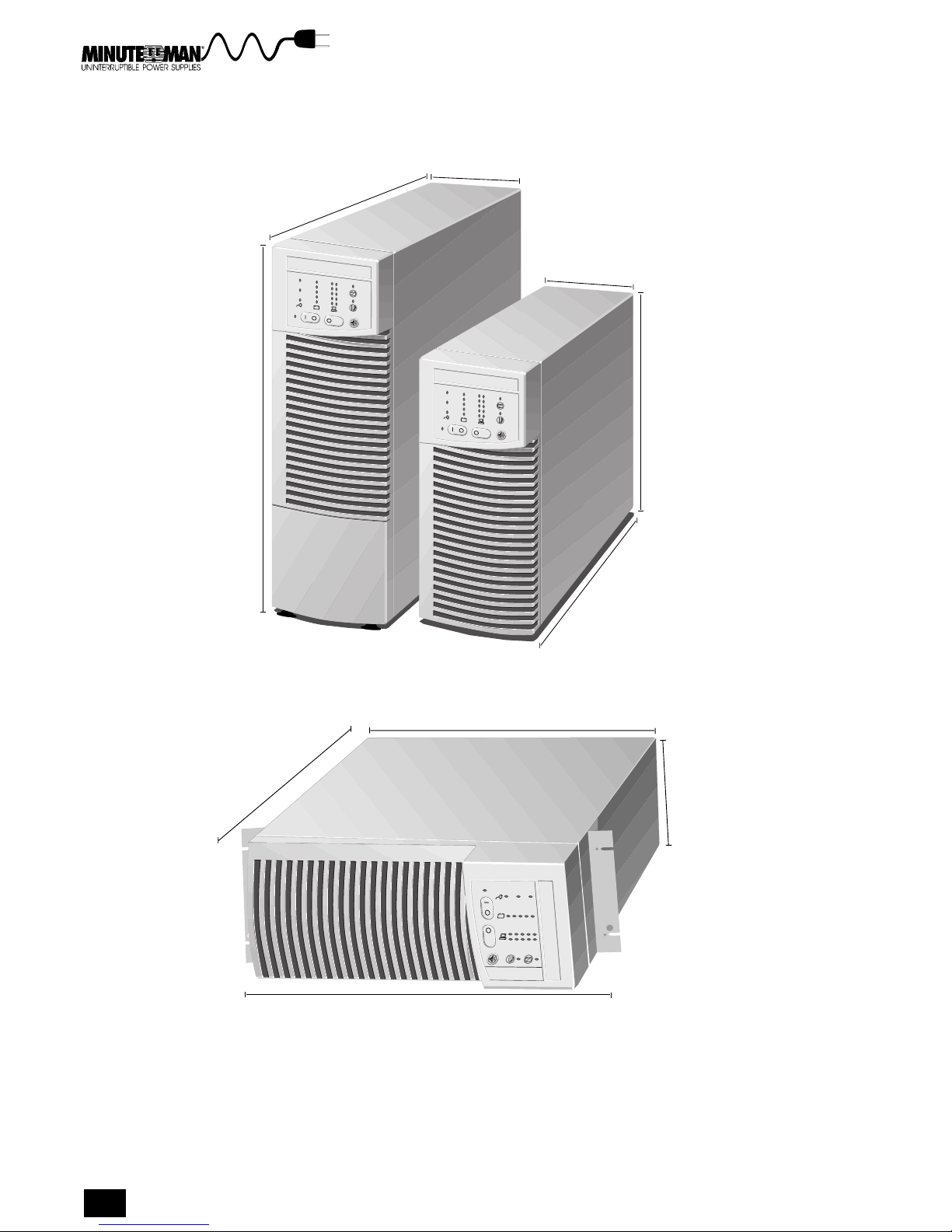
ON
24.0 in
(61.0 cm)
6.8 in
(17.2 cm)
6.8 in
(17.2 cm)
24.0 in
(61.0 cm)
(61.0 cm)
5.0 & 6.0 KVA
Tower
24 in
ON
2.1 & 3.1 KVA
Tower
16.0 in
(40.6 cm)
24.0 in
(61.0 cm)
16.0 in
(40.6 cm)
6.8 in
(17.2 cm)
Figure 1-1. The Continuous Power Series Tower and Rack-Mount Models
4
ON
19.0 in
(48.2 cm)
Including mounting wings
2.1 & 3.1 KVA Rack-Mount
Page 7
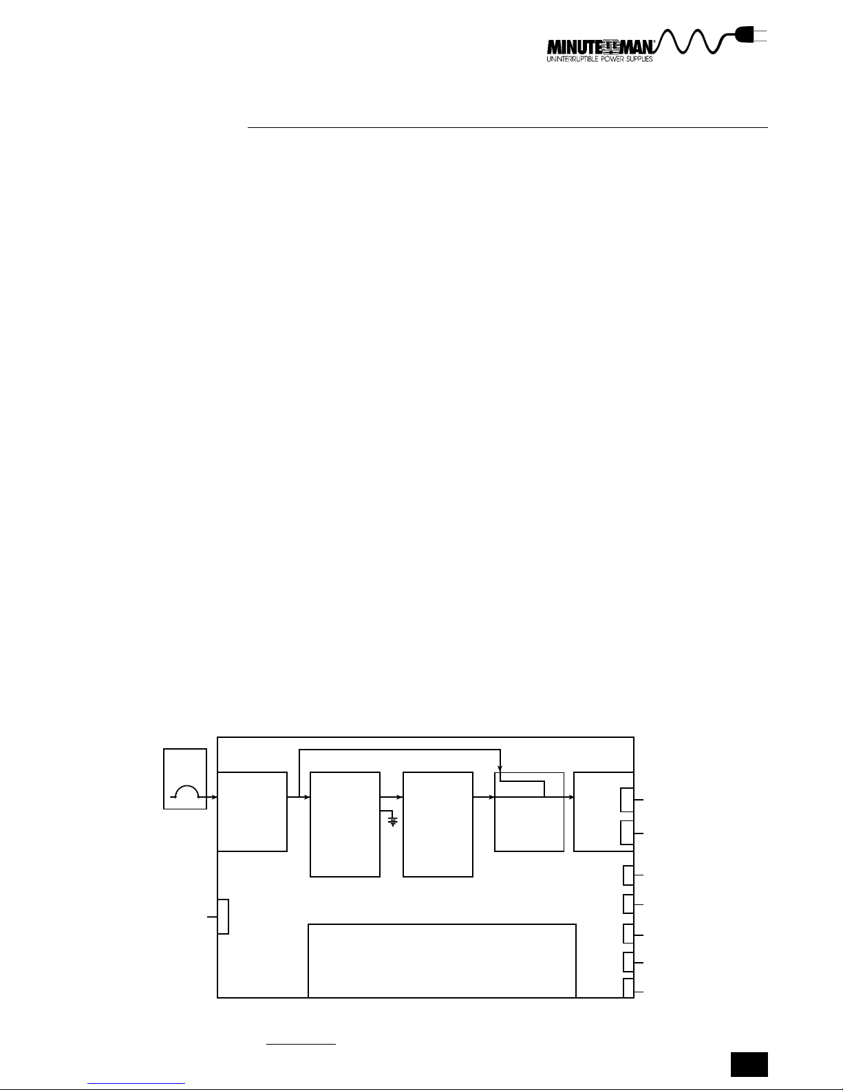
HOW THE CONTINUOUS POWER SERIES PROTECTS YOUR SYSTEM
The Continuous Power Series UPS has two basic functions:
Prevent AC line interruptions from disrupting your load (computer
network, workstations, etc.)
Condition poor quality AC power before it disrupts your load
AC power disturbances come in many forms, from full blackouts to radio
transmissions on a factory floor. The Continuous Power Series is designed to
respond to these power problems before they affect the operation of your
sensitive electrical equipment. Various types of AC power disturbances in-
clude:
No voltage (blackout)
Low voltage (brownout)
High voltage
Slow voltage fluctuation (voltage sag)
Frequency variations
Common mode noise
Normal mode noise
Utility
Source
• Hard wire
• Line cord
plug
(optional)
Additional
battery
Transients caused by switching and faults
Electrical disturbances can damage software, hardware, and cause equipment
to operate erratically. The Continuous Power Series protects equipment by
maintaining a constant output voltage and by conditioning poor quality AC
power before it reaches sensitive electric equipment. Because the Continuous
Power Series is a true online UPS, it also provides instantaneous backup
power during a power failure with no interruption to your load(s). The block
diagram in Figure 1-2 illustrates how the Continuous Power Series UPS is
connected to AC power and loads.
AUTO
TRANSFER
INPUT AC/DC DC/AC
• Filter
• Back feed
protection
• Rectification
• Amplification
• Input current
wave shaping
• Input PF
correction
• ABM
• Input Voltage level
• Battery level
• Load level
• Inverter
• Output Voltage
wave shaping
• Synchronizing
Front Panel
Function Block Diagram
SWITCH
X
X
• Redundancy
• Auto retransfer
• Alarms
• Audio alarm silence
• ON/OFF
OUTPUT
STD 5-15R +
Hard wire
Receptacles
(optional)
MBS (optional)
Start-on-battery
(optional)
RS-232 serial
comm. port
Modem comm.
port (optional)
Relay
contacts
Remote
emergency
power OFF
Section 1 Introduction
Minuteman Continuous Power Series UPS
5
Page 8

OPTIONS
The Minuteman Continuous Power Series is an option-rich UPS. Options are
listed below.
Second RS-232 communication port for a modem board
Start-on-battery
Manual bypass switch
Remote power warning interface kits
External battery packs
Optional output receptacles (see Appendix A for receptacle options)
Remote distribution box
Power management software
Input transformer
ABOUT THE MANUAL
This manual contains information you need to install and operate the Continu-
ous Power Series UPS. The information is intended for system administrators
or others with similar expertise in electronics. The field wiring instructions in
section 3, Installation, are intended for qualified electricians and technicians.
SCOPE
The manual explains all the necessary information to unpack, install, and
operate the Continuous Power Series UPS. It also provides information about
configuring, maintaining, and troubleshooting. Refer questions outside the
scope of this manual to your Minuteman dealer or Para Systems Technical
Support Department.
QUESTIONS?
Minuteman is committed to excellence in dependability and customer satisfac-
tion. If you have any questions or problems, please contact the Technical
Support Department at: 1-800-238-7272 or 214-446-7363 for more informa-
tion.
6
Page 9

PREPARATION
The Preparation section is designed to familiarize you with your UPS. The first
part explains unpacking the UPS, inspecting the unit, and safety precautions.
The remaining sections describe front and rear panels and user controls. Study
this section to become familiar with your UPS before installing the unit.
UNPACKING THE UPS
Unpack your UPS carefully to avoid damage. The following steps explain how
to remove the UPS from its pallet.
1. Cut the strap holding the UPS box to the pallet.
2. Remove the cardboard box and packing material surrounding the UPS.
3. Using an appropriate number of people, lift the UPS off the pallet and
set it down on its castors (3.1 KVA models come with small rubber
pads. Attach the rubber pads to the underside of the UPS before setting
the unit on the floor).
WARNINGWARNING
WARNING
WARNING!
WARNINGWARNING
The UPS weighs more than 125 pounds (56.7 kg). It is manda-
tory that the necessary precautions be taken to lift, move,
set, and position the UPS.
INSPECTING EQUIPMENT
Check your UPS for external damage. If any damage occurred during ship-
ment, keep the shipping cartons and packing materials so the carrier or your
Deltec dealer can inspect them. The following instructions explain how to file a
damage claim. If you discover damage after acceptance, file a claim for con-
cealed damage.
To file a claim for shipping damage or concealed damage:
File with the carrier within 15 days of receipt of the equipment
Send a copy of the damage claim within 15 days to:
Para Systems, Inc.
1455 LeMay Drive
Carrollton, Texas 75007
Attn: Customer Service Department
Minuteman Continuous Power Series UPS
7
Page 10
CHECKING PACKAGE CONTENTS
The following items should be included in your Continuous Power Series
package:
1 UPS unit
1 users manual
1 stabilizing bracket (6.0 KVA units only)
Warranty Registration Card
Platinum Protection Policy
If your UPS package does not contain these items contact your Minuteman
dealer. Optional equipment such as external battery packs are shipped in
separate containers. Contact your Minuteman dealer if the optional items you
ordered are not included in the shipment.
PRECAUTIONS
Please read all instructions before operating the equipment and save this
manual for future reference.
SAFETY INFORMASAFETY INFORMA
SAFETY INFORMA
SAFETY INFORMASAFETY INFORMA
SAVE THESE INSTRUCTIONS. This manual contains important
instructions that should be followed during installation and
maintenance of the UPS and batteries.
TIONTION
TION
TIONTION
WARNING!
Electric Shock Hazard. The batteries contain high voltages.
These voltages can damage equipment and injure or kill per-
sonnel.
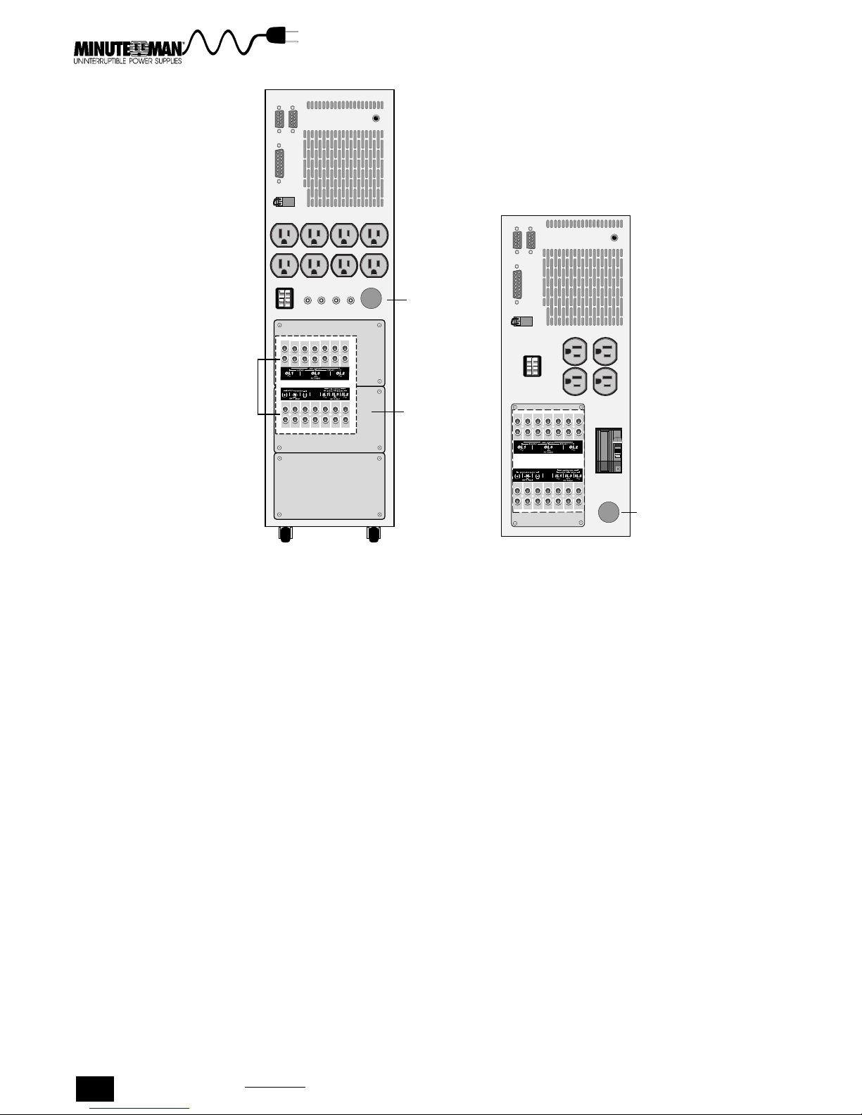
OVERVIEW OF THE UPS
The Minuteman Continuous Power Series has 10 standard models with power
ratings from 3.1 to 6.0 KVA. The front panel LED indicators and control but-
tons for tower and rack-mount models perform the same functions and indicate
the same information. The rear panels of each model vary depending on
options. Figure 2-1 shows the standard rear panels for hardwired tower mod-
els. Figure 2-2 shows the rear panel of the rack-mount hardwired model. All
models are also available with a plug and play option. Study these illustrations
to become familiar with your unit. The rear panels for plug and play units are
shown with the plug and play instructions in section 3, Installation.
Section 2 Preparation
8
Page 11
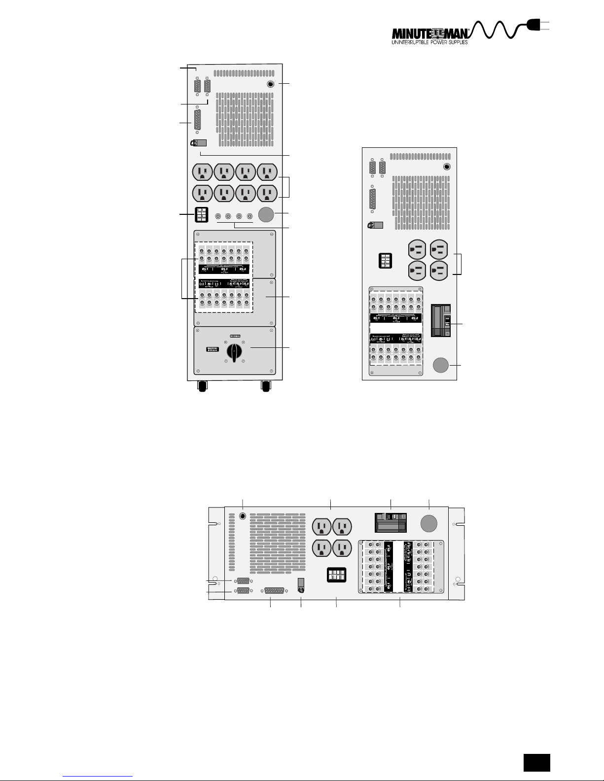
Standard
RS-232 Port
Optional Second
RS-232
Relay
Interface
Port
Ext. Battery
Connector
Terminal Blocks
(located behind
rear panel plates)
Optional
Start-On-Battery
Switch
REPO Port
5-15R
Standard
Receptacles
Conduit Hole
Circuit
Breakers
5-15R
Standard
Receptacles
Rear
Panel
Plates
Circuit
Breaker
Manual Bypass
Switch (optional)
Conduit
Hole
Optional
2nd RS-232
Standard
RS-232 Port
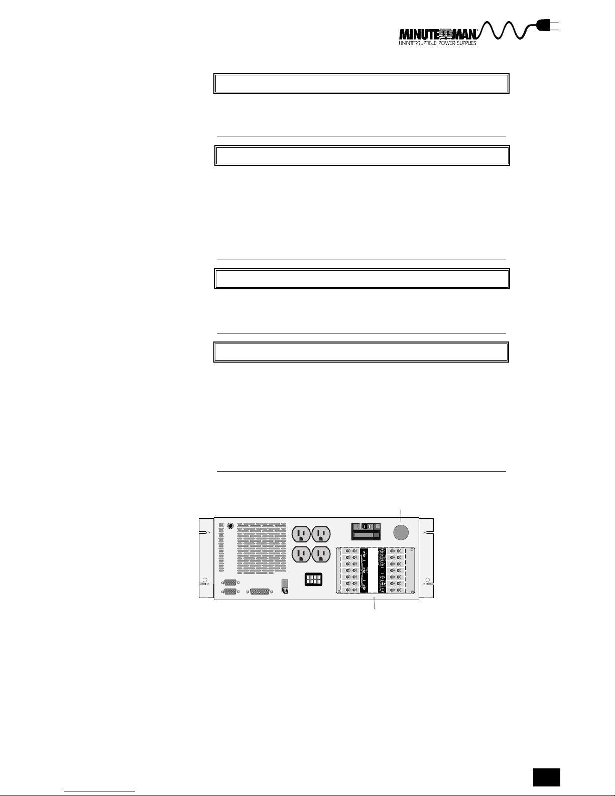
Figure 2-2. The Rear Panel of the Rack-Mount Model
5.0 & 6.0 KVA
2.1 & 3.1 KVA
Models
Figure 2-1. The Rear Panels of Tower Models
Optional Start-On-
Battery Switch
Relay
Interface
Port
Standard
Receptacles
Ext. Battery
REPO
Connector
Port
2.1 & 3.1 KVA Models
Circuit
Breaker
Terminal Blocks
Models
Conduit
Hole
(behind rear
panel plates)
Minuteman Continuous Power Series UPS
9
Page 12

FRONT PANEL CONTROL BUTTONS
The front panels of all models have the same control buttons. The control
buttons allow you to operate the UPS and configure the units parameters.
Using the control buttons is explained in section 4, Operation.
FRONT PANEL LED INDICATORS
The front panel LED indicators (small colored lights) on all models indicate
how the UPS is functioning. On tower models the LEDs are placed vertically
on the front panel. On rack-mount models the LEDs are placed horizontally.
There are LED indicators for AC input, battery charge, load, battery service
requirement, and bypass mode. LEDs also indicate parameters when the UPS
is in configure mode.
REAR PANELS
The rear panels of all models come standard with an RS-232 port and a relay
interface port, and a remote emergency power off (REPO) port. The RS-232
port and cable are used to connect the UPS to a host computer and are
compatible with Minuteman Network Manager II software. The relay interface
port supports AC line failure alarm, impending low battery alarm, summary
alarm, load-on-bypass alarm, and other dry-contact type devices. The REPO
port supports standard REPO operation. The rear panel also includes standard
5-15R receptacles, circuit breakers, and a battery pack connector for the
optional external battery pack.
Section 2 Preparation
10
Page 13

INSTALLATION
3
The Installation section explains positioning the UPS and connecting the AC
input and loads for both hardwired models and plug and play models. The
section then explains how to connect the input transformers and the optional
external battery packs (if included). Installing the communication ports and
other options are explained at the end of the section.
POSITIONING THE UPS
When locating tower and rack-mount models consider the following guidelines:
TOWER
Avoid temperature and humidity extremes. To maximize the lifetime of
the batteries, an ambient temperature of 59°F to 77°F (15°C to 25°C) is
recommended.
Provide shelter from the elements (especially moisture).
make sure ventilation and space requirements are met. There should
be two inches (5 cm) of clearance at both sides and on top of the UPS.
Four inches (10 cm) of clearance is needed at the rear of the UPS for
ventilation.
Maintain clearance at the front of the UPS for user operations.
Install the external battery pack next to the UPS.
RACK-MOUNT
The rack-mount UPS fits into a standard equipment rack (mounting
hardware is not provided).
To maximize the life of the UPS internal batteries, avoid temperature
and humidity extremes.
The ambient temperature should be kept around 59°F to 77°F
(15°C to 25°C).
ATTACHING THE STABILIZING BRACKET
6.0 KVA units come with a stabilizing bracket used to secure the unit once it is
placed. Follow the instructions below to attach the stabilizing bracket.
1. Remove the bottom two screws of the bottom rear panel plate.
2. Place the stabilizing bracket over the bottom of the plate, as shown in
Figure 3-1, and attach it using the screws removed from the plate.
Minuteman Continuous Power Series UPS
11
Page 14
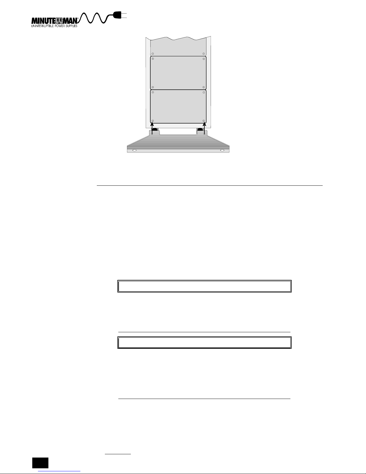
Figure 3-1. Attaching the Stabilizing Bracket to the UPS
CONNECTING THE HARDWIRED UPS
Hardwired units have input and output terminal blocks that connect directly to
the AC input source and load(s). The terminal blocks are located on the rear
panel, behind the rear panel plates as shown in Figure 3-2 and 3-3. This
section explains how to select the wiring, locate the terminal blocks, and
connect your loads and AC input.
Please note that the first boldfaced sentence of each step explains the step
briefly. The remaining text explains the step in greater detail.
Also note the following Pre-installation Considerations before beginning instal-
lation procedures.
PRE-INSTALLATION CONSIDERATIONS
WARNINGWARNING
WARNING
WARNING
WARNINGWARNING
ELECTRICAL SHOCK HAZARD. The hardwired models must be
installed by a qualified electrician or technician, or some other
qualified personnel. The UPS and batteries may contain HIGH
VOLTAGES. These high voltages can injure or kill personnel
and damage equipment.
1. The UPS batteries are sealed, lead-acid, and mainte-
2. Operate the UPS in a protected environment within a
Section 3 Installation
12
NONO
TETE
NO
TE
NONO
TETE
NOTE
nance-free. These batteries are designed to give their
longest service when used in an ambient temperature
of 77°F (25 °C).
temperature range of 23°F to 104°F (0°C to 40°C) and a
relative humidity of 0-95%, without condensation.
Page 15
WARNINGWARNING
WARNING
WARNINGWARNING
WARNING!
The UPS weighs more than 125 pounds (56.7 kg). It is manda-
tory that the necessary precautions be taken to lift, move,
set, and position the UPS.
NONO
TETE
NO
TE
NOTE
NONO
TETE
Current limiting and mechanical disconnect devices, sup-
plied by the customer, between the UPS and the input source
must be installed prior to operating a hardwired UPS. It is rec-
ommended that current limiting and mechanical disconnect
devices also be installed between the UPS and the load.
Follow the National Electric Code where applicable during
installation.
WARNINGWARNING
WARNING
WARNINGWARNING
WARNING!
To reduce the risk of fire or electric shock, install in a tem-
perature and humidity controlled indoor area free of con-
ductive contaminants.
WARNINGWARNING
WARNING
WARNING!
WARNINGWARNING
Do the following BEFORE CONNECTING ANY WIRING:
TURN OFF the UPS by pushing the ON/OFF and OFF but-
tons at the same time.
TURN OFF all input power (AC and DC)
TURN OFF the critical load (Any transformers or motors in
front of the load are considered part of the load
VERIFY WITH A METER that the power is removed
Conduit Hole
Terminal Blocks
(behind rear panel plates)
Rack-Mount
Figure 3-2. Rear Panel of the Rack-Mount Models
Minuteman Continuous Power Series UPS
13
Page 16
Terminal Blocks
(located behind
rear panel plates)
Conduit
Hole
Rear
Panel
Plates
Conduit
Hole
5.0 & 6.0 KVA Tower
2.1 & 3.1 KVA Tower
Figure 3-3. Rear Panels for Standard Hardwired Models
STEPS FOR FIELD WIRING
c
SPECIAL CAUTION: THE CP3200 & CP6000, 2 PHASE UNITS, REQUIRE A 4 WIRE INPUT.
THIS UNIT WILL BE DAMAGED, AND WILL NO LONGER FUNCTION IF THE INPUT IS
INCORRECTLY WIRED. DO NOT ATTEMPT TO OPERATE UNIT UNLESS INSTALLED
CORRECTLY.
CONSULT WITH A QUALIFIED ELECTRICIAN IF THIS UNIT IS A PLUG AND PLAY (PP) UNIT
AND WALL OUTLET DOES NOT MATCH FOR A DIRECT CONNECTION.
THE FOLLOWING MODELS ARE 2 PHASE UNITS:
1. CP3200 2. CPR3200 3. CP3200-PP
4. CPR3200-PP 5. CP6000 6. CP6000-PP
1. If you are installing a transformer, it must be connected to AC
input before installing the UPS. See Installing the Transformer later
in this section for step-by-step instructions. If you are not installing a trans-
former got to step 2.
2. Select the input and output wiring. The UPS has compression-
type terminal blocks for input and output connections. The UPS uses
#10 AWG wire torqued to 35 in-lb. Use the National Electrical Code
Article 310, Table 310 (60° column only) to determine the appropriate
wiring. Use only copper conductors and follow all pertinent local electri-
cal codes when selecting wiring.
3. Provide an AC input line that meets the UPS electrical input
requirements. Verify that the capacity of the UPS and the capacity of
the input circuit are the same (the rating of the external circuit breakers
must match the AC input rating). Refer to Table 3-1 for the recom-
mended circuit breaker size.
14
Section 3 Installation
Page 17
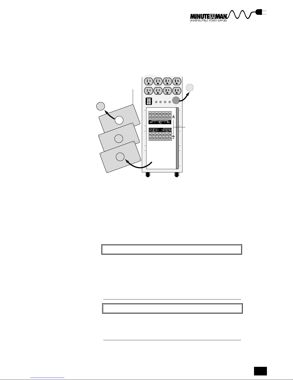
4. Remove the rear panel plates at the back of the UPS as shown
in Figure 3-4. The two sets of terminal blocks consist of seven
(7) terminals each. Six (6) of the terminals on the AC input and
battery input block are used for connections. The remaining
terminal is not connected. Follow the terminal block labels
when connecting wires.
Removed
Rear Panel
Plates
Knockout
from second
conduit hole
Removed
Plug Cap
Exposed
Terminal
Blocks
Figure 3-4. Removing the Rear Panel Plates and Plug Cap
5. Remove plug cap and knockout and attach conduit. Remove
the plastic plug cap from the conduit hole and attach flexible
wiring conduit to the conduit hole. Create a second conduit
hole by punching out a knockout from one of the rear panel
plates, as shown in Figure 3-4, and attach a second conduit.
6. Route the input and output wiring. Route the wiring for the AC
input and loads through separate conduit to the terminal
blocks.
CACA
UTIONUTION
CA
UTION
CACA
UTIONUTION
CAUTION!
Avoid damage. Do not remove, cut, or modify any of the
wiring connected to the terminal blocks by the factory. For
input wiring, connect only ONE WIRE to each terminal. For
output wiring, more than one wire may be connected to a
terminal. The UPS or your load may be damaged if any of
the factory-installed wiring is cut, broken, removed, or modi-
fied in any way.
NONO
TETE
NO
TE
NONO
TETE
NOTE
The National Electrical Code requires that a current limiting
device (provided by the customer) must be installed be-
tween the input line to the UPS and between the UPS and
the output line when hard wired.
7. Connect a current limiting device between the AC input and
the UPS. Refer to Table 3-1 for the recommended circuit
breaker size for each model.
Minuteman Continuous Power Series UPS
15
Page 18
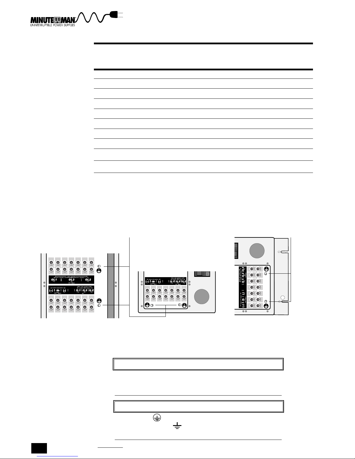
Table 3-1. Recommended AC Circuit Breaker Size
Recommended AC
Model Circuit
Size (AMPS) Breaker
CP3000 20 A - 1 Pole
CP3000-PP 20 A - 1 Pole
CPR3000 30 A - 1 Pole
CPR3000-PP 30 A - 1 Pole
CP3200 15 A - 2 Pole
CP3200-PP 15 A - 2 Pole
CPR3200 30 A - 2 Pole
CPR3200-PP 30 A - 2 Pole
CP6000 30 A - 2 Pole
CP6000-PP 30 A - 2 Pole
8. Connect and secure the ground wires. Refer to Figure 3-5 for
grounding stud locations. There are two grounding stud loca-
tions for each unit. Connect the AC input ground wire to the
primary grounding stud and the load ground wires to the sec-
ondary grounding stud.
Grounding
Studs
5.0 and 6.0 KVA
6.0 KVA 3.1 KVA 3.1 KVA
Tower
Tower Tower Rack-Mount
2.1 and 3.1 KVA
Tower
2.1 and 3.1 KVA
Rack-Mount
Figure 3-5. Grounding Stud Locations for Tower and Rack-Mount Models
WARNINGWARNING
WARNING
WARNINGWARNING
WARNING!
ELECTRICAL SHOCK HAZARD. The UPS may contain HIGH VOLT-
AGES. These high voltages can damage equipment and in-
jure or kill personnel.
Grounding
Studs
This symbol indicates primary equipment grounding
point. This symbol indicates secondary equipment
grounding point.
16
Section 3 Installation
NONO
NO
NONO
NOTE
TETE
TE
TETE
Page 19

SPECIAL CAUTION: THE CP3200 & CP6000, 2 PHASE UNITS, REQUIRE A 4 WIRE INPUT. THIS
UNIT WILL BE DAMAGED, AND WILL NO LONGER FUNCTION IF THE INPUT IS INCORRECTLY
WIRED. DO NOT ATTEMPT TO OPERATE UNIT UNLESS INSTALLED CORRECTLY.
CONSULT WITH A QUALIFIED ELECTRICIAN IF THIS UNIT IS A PLUG AND PLAY (PP) UNIT AND
WALL OUTLET DOES NOT MATCH FOR A DIRECT CONNECTION.
THE FOLLOWING MODELS ARE 2 PHASE UNITS:
1.CP3200 2.CPR3200 3.CP3200-PP
4.CPR3200-PP 5.CP6000 6.CP6000-PP
9. Connect the AC input and output wiring according to the UPS
Input and Output Wiring Tables and Figures. Table 3-2 and
Figure 3-6 explain connecting single-phase units. Table 3-3 and
Figure 3-7 explain connecting two-phase units. Check the UPS identifi-
cation label to verify that the power rating for your load matches the
power rating of the UPS. Refer to the terminal block illustrations in
Figure 3-9 and Figure 3-10 for the correct terminal locations. The block
diagram in Figure 3-8 gives an overview of UPS connections.
NONO
TETE
NO
TE
NONO
TETE
NOTE
Input Line 2 (IL2) and Output Line 2 (OL2) on the terminal
blocks are used for two-phase units only. These terminals are
not connected on single-phase units.
NOTE
NONO
TETE
NO
TE
NONO
TETE
If your UPS has an optional load circuit breaker plate, go to
Installing Output Circuit Breaker later in this section to con-
nect loads through the output circuit breaker.
CACA
UTIONUTION
CA
UTION
CACA
UTIONUTION
CAUTION!
Utility neutral must be connected to the neutral terminal (IL3)
on all hardwired units. Failure to connect the neutral can
damage the unit.
Table 3-2. UPS Input and Output Wiring Chart for Single-Phase Models
AC Input to UPS Input (single-phase)
Connect this Wire To this Terminal in the UPS
Utility GROUND Grounding Stud
Utility Neutral IL3 (Neutral)
Utility Line 1 (hot) IL1 (Line 1)
Load to UPS Output (single-phase)
Connect this Wire To this Terminal in the UPS
Load Ground Grounding Stud
Load Neutral OL3 (Neutral)
Load Line 1 (hot) OL1 (Line 1)
Minuteman Continuous Power Series UPS
17
Page 20

UPS
Utility
Hot
Neutral must be connected. Failure to do so can damage the unit.
1
CB
Ground
Neutral
Line 1
Ground
1
IL3
IL1
OL3
OL1
Neutral
Line 1
Loads
Figure 3-6. AC Input and Output Wiring Diagram for Single-Phase Models
Table 3-3. UPS Input and Output Wiring Chart for Two-Phase Models
AC Input to UPS Input (two-phase)
Connect This Wire To This Terminal in the UPS
Utility GROUND Grounding Stud
Utility Neutral IL3 (Neutral)
Utility Line 1 (hot) IL1 (Line 1)
Utility Line 2 (hot) IL2 (Line 2)
Load to UPS Output (two-phase)
Connect This Wire To This Terminal in the UPS
Load Ground Grounding Stud
Load Neutral OL3 (Neutral)
Load Line 1 (hot) OL1 (Line 1)
Load Line 2 (hot) OL2 (Line 2)
UPS
Utility
Hot
Hot
Neutral must be connected. Failure to do so can damage the unit.
1
CB
Ground
Neutral
Line 1
Line 2
1
IL3
IL1
IL2 0L2
OL3
OL1
Ground
Neutral
Line 1
Line 2
Loads
Figure 3-7. AC Input and Output Wiring Diagram for Two-Phase Models
Section 3 Installation
18
Page 21

AC INPUT
UPS
(Field-Wired Models)
JL1
JL2
5-15R Duplex
AC Power Source
CB-1
Hot
Hot
Neutral
Ground
External DC Power
Source
Ground
CB-2
(30A)
Positive
Negative
Neutral
BATTERY INPUT
NOTES:
1
All switchgear and connections outside of the UPS must be supplied by the
customer. The National Electrical Code requires that an overcurrent and a disconnect
device (provided by the customer) must be installed between the UPS and the AC input.
5
1
Line 1
Line 2
Neutral
Ground
2
IL1
IL2
IL3(N)
(+)
(–)
N
Optional
Recep.
Plates
JB
JC
JA
OL1
OL2
OL3(N)
J2
J3
TB1
J3O
J4
Line 1
Line 2
5
Neutral
Ground
Serial Comm. Port (Std.)
Dry Contacts (Std.)
REPO (Std.)
Modem Port (Option)
Start On Battery (Option)
4
Load
Distribution
3
The National Electrical Code requires that a distribution system which contains an
2
overcurrent and a voltage disconnect device (provided by the customer) must be
installed between the UPS and the external DC source.
3
See Interface Ports later in this section for details about the User Interface
Connectors.
4
The National Electrical Code requires that an overcurrent and a disconnect device
(provided by the customer) must be installed between the UPS and the load.
Use for two-phase models only. Terminal is not connected on one-phase models.
5
Figure 3-8. UPS Wiring Diagram
Minuteman Continuous Power Series UPS
19
Page 22

Figure 3-9. Terminal Blocks for 3.1 KVA Units
Used only for
two-phase units,
dead on singlephase units.
Used only for
two-phase units,
dead on singlephase units.
Figure 3-10. Terminal Blocks for the 3.1 & 6.0 KVA Two-Phase Units
Section 3 Installation
20
Page 23

10. Replace the rear panel plates and secure with the screws.
Make sure the conduit is seated properly.
11. If you are not connecting external battery packs or an exter-
nal DC source, installation is now complete. Go to section 4,
Operation, for instructions about operating the UPS. To connect exter-
nal battery packs see the Connecting the External Battery Packs
instructions later in this section. To connect external DC sources see
Connecting External DC Source later in this section.
CONNECTING THE PLUG AND PLAY UPS
Plug and play power connections allow you to plug your UPS into an AC wall
outlet and your loads into the output receptacles at the rear panel of the UPS.
The steps below explain how. Figure 3-11 and 3-12 show the rear panels of the
plug and play units.
WARNING!
WARNINGWARNING
WARNING
WARNINGWARNING
To reduce the risk of fire or electric shock install in a tempera-
ture and humidity controlled indoor area free of conductive
contaminants.
SPECIAL CAUTION: THE CP3200 & CP6000, 2 PHASE UNITS, REQUIRE A 4 WIRE
INPUT. THIS UNIT WILL BE DAMAGED, AND WILL NO LONGER FUNCTION IF THE
INPUT IS INCORRECTLY WIRED. DO NOT ATTEMPT TO OPERATE UNIT UNLESS
INSTALLED CORRECTLY.
5 -15 Standard
Receptacles
Ext. Battery
Connector
CONSULT WITH A QUALIFIED ELECTRICIAN IF THIS UNIT IS A PLUG AND PLAY
(PP) UNIT AND WALL OUTLET DOES NOT MATCH FOR A DIRECT CONNECTION.
THE FOLLOWING MODELS ARE 2 PHASE UNITS:
1. CP3200 2. CPR3200 3. CP3200-PP
4. CPR3200-PP 5. CP6000 6. CP6000-PP
AC Line
Cord
Optional
Receptacles
5.0 & 6.0 KVA Models 2.1 & 3.1 KVA Models
Figure 3-11. Rear Panel of Tower Models With Plug and Play Option
6.0 KVA Models 3.1 KVA Models
Minuteman Continuous Power Series UPS
21
Page 24

Standard 5-15
Receptacles
Circuit
Breaker
Optional
Receptacles
AC Line
Cord
Figure 3-12. Rear Panel of Rack-Mount Models With Plug and Play Option
STEPS TO INSTALL PLUG AND PLAY POWER CONNECTIONS
1. Plug in the optional transformer first. If you are not installing a transformer
go to step 2. If you are installing a transformer, it must be plugged into an
AC outlet before installing the UPS. See Installing a Plug and Play Trans-
former later in this section for step-by-step instructions.
2. Plug the UPS line cord into an AC outlet.
3. Plug your loads into the UPS using the receptacles at the rear panel.
NONO
TETE
NO
TE
NOTE
NONO
TETE
DO NOT plug laser printers into the UPS.
4. If you are not connecting external battery packs or an external DC
source, installation is now complete. Go to section 4, Operation, for
instructions about how to operate the UPS. To connect external batter-
ies see the Installing the External Battery Packs instructions later in this
section. To connect external DC sources, see Connecting External DC
Source later in this section.
INSTALLING THE OPTIONAL TRANSFORMER
The optional transformer has either hardwired or plug and play connections
depending on the model you have. Hardwired models have compression type
terminal blocks that connect directly to the AC input and loads. Plug and play
models have a line cord that connects to a wall outlet and receptacles to plug
loads into the UPS.
CONNECTING HARDWIRED TRANSFORMER
This set of instructions explains connecting the hardwired transformer and
UPS. The instructions also explain how to install the transformer if the UPS
is already connected. The first boldfaced sentence of each step explains
the step briefly. The remaining text describes the step in greater detail.
Section 3 Installation
22
Page 25

Please note the following Pre-installation Considerations before installing
the transformer and UPS.
PRE-INSTALLATION CONSIDERATIONS
WARNINGWARNING
WARNING
WARNINGWARNING
WARNING!
ELECTRICAL SHOCK HAZARD. The hardwired models must be
installed by a qualified electrician or technician, or some other
qualified personnel. The UPS and batteries may contain HIGH
VOLTAGES. These high voltages can injure or kill personnel and
damage equipment.
NONO
TETE
NO
TE
NONO
TETE
NOTE
1. The UPS batteries are sealed and maintenance-free.
These batteries are designed to give their longest ser-
vice when used in an ambient temperature of 77°F (25
°C).
2. Operate the UPS and transformer in a protected envi-
ronment within a temperature range of 23°F to 104°F
(0°C to 40°C) and a relative humidity of 0-95%, with-
out condensation.
WARNINGWARNING
WARNING
WARNING!
WARNINGWARNING
The UPS and transformer each weigh more than 125 pounds
(56.7 kg). It is mandatory that the necessary precautions be
taken to lift, move, set, and position the UPS.
NONO
TETE
NO
TE
NONO
TETE
NOTE
Current limiting and mechanical disconnect devices between
the transformer and the input source must be installed prior to
operating a hardwired UPS and transformer. It is recommended
that current limiting and mechanical disconnect devices also
be installed between the UPS and the load. Follow the Na-
tional Electric Code where applicable during installation.
WARNINGWARNING
WARNING
WARNINGWARNING
WARNING!
Do the following BEFORE CONNECTING or DISCONNECTING
ANY WIRING:
TURN OFF the UPS by pressing the ON/OFF and OFF but-
tons at the same time.
TURN OFF all input power (AC and DC).
TURN OFF the critical load (Any transformers or motors in
front of the load are considered part of the load.
VERIFY WITH A METER that the power is removed.
Minuteman Continuous Power Series UPS
23
Page 26

STEPS FOR INSTALLING THE TRANSFORMER AND UPS
1. Select the input and output wiring for the UPS and transformer. If the
UPS is already installed, go to step 3. The transformer and UPS use
#10 AWG size wire torqued to 35 in-lb. Use only copper conductors
and follow all pertinent local electrical codes.
2. Provide an AC input line that meets both the UPSs and transformers
electrical requirements. Verify that the operation of the transformer and
UPS does not exceed the rated capacity of the circuit (the rating of the
external circuit breakers must match the AC input rating).
3. Remove the rear panel plates from the transformer and the UPS to
expose the terminal blocks.
4. If the UPS is already installed, disconnect the AC input from the UPS
terminal blocks according to Table 3-4, UPS Disconnect Chart. If the
UPS is not installed, go to step 6.
WARNINGWARNING
WARNING
WARNINGWARNING
WARNING!
ELECTRICAL SHOCK HAZARD. The hardwired transformers must
be installed by a qualified electrician or technician, or some
other qualified personnel. The UPS and batteries may contain
HIGH VOLTAGES. These high voltages can injure or kill personnel
and damage equipment.
Table 3-4. UPS Disconnect Chart
Disconnecting AC Input from the UPS
Disconnect This Wire From This Terminal on the UPS
Utility GROUND Grounding Stud
Utility Neutral IL3 (Neutral)
Utility Line 1 (hot) IL1 (Line 1)
Utility Line 2 (hot) two-phase only IL2 (Line 2) two-phase only
5. Remove the AC input wiring from the UPS conduit.
6. Remove the two knockouts from the rear panel plates of the transformer
and attach flexible conduit to each hole.
7. Route the AC input and output wiring through each conduit to the
terminal blocks of the transformer.
CACA
UTIONUTION
CA
UTION
CACA
UTIONUTION
CAUTION!
Avoid damage. Do not remove, cut, or modify any of the
wiring connected to the terminal blocks by the factory. For
input wiring, connect only ONE WIRE to each terminal. For
output wiring, more than one wire may be connected to a
terminal. The UPS or your load may be damaged if any of
the factory-installed wiring is cut, broken, removed, or modi-
fied in any way.
24
Section 3 Installation
Page 27

NONO
TETE
NO
TE
NONO
TETE
NOTE
The National Electrical Code requires that a current limiting
device (provided by the customer) must be installed be-
tween the input line to the UPS when hardwired.
c
8. Connect a current limiting device between the AC input and the trans-
former.
WARNINGWARNING
WARNING
WARNINGWARNING
WARNING!
ELECTRIC SHOCK HAZARD. A battery can present a risk of
electric shock and high short circuit. BE CAREFUL when mak-
ing connections to terminals. HIGH VOLTAGES may be present
which can injure or kill personnel and damage equipment.
NONO
TETE
NO
TE
NONO
TETE
NOTE
Attach the AC input and output grounds to the transformer
before attaching any other wires.
9. Connect the AC input and output wiring to the transformer terminal
block according to the Transformer Wiring Chart, Table 3-5. The wiring
diagram in Figure 3-13 illustrates the wire connections. Figure 3-14
shows the terminal block and label.
CACA
UTIONUTION
CA
UTION
CACA
UTIONUTION
CAUTION!
Utility neutral must be connected to the neutral terminal (IL3)
on all hardwired units. Failure to connect the neutral can
damage the unit.
Table 3-5. Transformer Wiring Chart
AC Input to Transformer
Connect This Wire To This Terminal in the Transformer
Utility GROUND Grounding Stud
Utility Neutral IL3 (Neutral)
Utility Line 1 (hot) IL1 (Line 1)
Utility Line 2 (hot) two-phase only IL2 (Line 2) two-phase only
Output to Transformer
Connect This Wire To This Terminal on the Transformer
Output Ground Grounding Stud
Output (Neutral) OL3 (Neutral)
Output Line 1 (hot) OL1 (Line 1)
Output Line 2 (hot) two-phase only OL2 (Line 2) two-phase only
Minuteman Continuous Power Series UPS
25
Page 28

Transformer
Output
wiring
c
Utility
CB
Hot
Hot
Neutral must be connected. Failure to do so can damage the unit.
1
2
Two-phase models only.
Ground
Neutral
Line 1
Line 2
Ground
1
IL3
IL1
2
IL2*
OL3
OL1
OL2*
Neutral
Line 1
Line 2
Figure 3-13. AC Input Transformer Wiring Diagram
Used only for
two-phase units,
dead on single-phase units
1
2
Figure 3-14. Transformer Terminal Block
10. Remove the UPS plug cap and knockout and attach conduit to each
hole. Remove the plug cap from the conduit hole and a knockout from a
rear panel plate of the UPS. Attach conduit to both holes. If conduit is
already attached, go to step 11.
11. Route the transformer output wiring through the UPS conduit and
connect it to the UPS terminal block according to the Transformer
Output Wiring to UPS Chart, Table 3-6. The wiring diagram in Figure 3-
15 shows how the transformer is connected to the UPS.
WARNINGWARNING
WARNING
WARNINGWARNING
WARNING!
ELECTRIC SHOCK HAZARD. A battery can present a risk of
electric shock and high short circuit. BE CAREFUL when mak-
ing connections to terminals. HIGH VOLTAGES may be present
which can injure or kill personnel and damage equipment.
CACA
UTIONUTION
CA
UTION
CACA
UTIONUTION
CAUTION!
Utility neutral must be connected to the neutral terminal (IL3)
on all hardwired units. Failure to connect the neutral can
damage the unit.
Section 3 Installation
26
Page 29

c
Table 3-6. Transformer Output Wiring to UPS Chart
Transformer Output Wiring to UPS
Connect This Wire From the Transformer To This Terminal in the UPS
Output Ground Grounding Stud
OL3 Neutral IL3 (Neutral)
OL1 Line 1 (hot) IL1 (Line 1)
OL2 Line 2 (hot) two-phase only IL2 (Line 2) two-phase only
Transformer UPS
Ground
IL3
IL1
IL2
Neutral must be connected. Failure to do so can damage the unit.
1
2
Used for two-phase units only
OL3
OL1
OL2
Neutral
Line 1
Line 2
1
IL3
IL1
2
IL2
OL3
OL1
OL2
Figure 3-15. Transformer to UPS Wiring Diagram
12. Route the load wiring through the other UPS conduit and connect it to
the UPS terminal according to the Load to UPS Wiring Chart, Table 3-
7. Figure 3-16 illustrates how the load wires connect to the UPS. If
loads are already connected to the UPS, go to step 13.
WARNING!
WARNINGWARNING
WARNING
WARNINGWARNING
ELECTRIC SHOCK HAZARD. A battery can present a risk of elec-
tric shock and high short circuit. BE CAREFUL when making con-
nections to terminals. HIGH VOLTAGES may be present which
can injure or kill personnel and damage equipment.
Table 3-7. Load to UPS Wiring Chart
Load to UPS
Attach This Wire To This Terminal on the UPS
Load Ground Grounding Stud
Load Neutral OL3 (Neutral)
Load Line 1 OL1 (Line 1)
Load Line 2 (two-phase only) OL2 (Line 2) (two-phase only)
Minuteman Continuous Power Series UPS
27
Page 30

UPS
Ground
Loads
1
IL3
IL1
IL2
1
Used for two-phase units only.
OL3
OL1
OL2
Neutral
Line 1
Line 2
Figure 3-16. Load to UPS Wiring Diagram
13. Replace the rear panel plates on both the transformer and UPS. Be
sure the conduit is sealed.
14. Installation is now complete. Go to section 4, Operation, for instructions
about how to operate the UPS. To connect external batteries see the
Installing the External Battery instructions later in this section. To
connect external DC sources see Connecting External DC Source later
in this section.
INSTALLING OPTIONAL PLUG AND PLAY TRANSFORMER
The instructions below explain installing transformers with plug and play
connections. Figure 3-17 shows how the plug and play transformer connects
to the UPS.
1. If the UPS is plugged into an AC outlet, turn the loads and the UPS off.
If the UPS is not installed, go to step 3.
2. Unplug the UPS line cord from the AC outlet.
3. Plug the transformer line cord into the AC outlet.
4. Plug the UPS line cord into the output receptacle at the rear panel of
the transformer.
5. If loads are already connected go to step 6. Plug your loads into the
receptacles at the rear panel of the UPS.
6. Installation is complete. You can now turn the UPS and loads on or
refer to section 4, Operation for information on how to operate the UPS.
Section 3 Installation
28
Page 31

AC Utility
Outlet
Output
Receptacle
UPS Line
Cord
Transformer
UPS
Figure 3-17. Installing a Plug and Play Transformer to the UPS
INSTALLING EXTERNAL BATTERY PACKS
Battery packs supplied by Minuteman have plug and play connections. The
following instructions describe connecting the external battery packs to the
UPS. The section also explains using the battery upgrade program to
reconfigure the UPS for the external batteries. If you are using an alternate
external DC source, see Installing Customer Supplied External DC Sources
later in this section.
WARNINGWARNING
WARNING
WARNINGWARNING
WARNING!
ELECTRICAL SHOCK HAZARD. Do not attempt to change the
wiring in either the battery pack plug or battery pack recep-
tacle. Attempting to alter plugs or receptacles wiring can
injury or kill personnel. If plugs and receptacles do not match
call your Minuteman representative.
1. Plug the battery line cord into the external battery connector at the rear
panel of the UPS. Figure 3-18 shows the location of the connector.
Push the battery pack plug into the connector quickly and firmly.
2. To connect more than one battery pack, connect the line cord of the
3. The external battery pack is now installed. Go to the next section to
second battery to the battery connector of the first battery. Repeat this
arrangement for each additional battery pack, as shown in Figure 3-18.
reconfigure the UPS for the external batteries.
Minuteman Continuous Power Series UPS
29
Page 32

External
Battery
Connector
UPS
External Battery External Battery
Ext. Battery
Connector
External
Battery
Line Cord
Figure 3-18. Connecting Battery Packs to the UPS
RECONFIGURING RUN TIME AND LOW BATTERY WARNING
Adding external batteries requires you to reconfigure the UPSs battery run
time and low battery warning. To accomplish this, a program disk called
PWRS Battery Upgrade is included with your external battery pack(s).
c
System Requirements:
DOS 2.0 or greater; or
Windows 3.0 or greater.
After connecting the external battery pack(s), follow the steps below to use the
PWRS Battery Upgrade program.
1. Connect the UPS to a host computer through the RS-232 port using
the interface cable that accompanied your UPS.
2. Place the PWRS Battery Upgrade disk in the computers floppy drive.
3. If you are using DOS, type Battery n at the prompt (n= the number of
external battery packs connected to the UPS. For example, if you have
connected 2 battery packs, enter Battery 2). Then press return.
4. If you are using Windows, select FILE from the Program Manager and
choose Run. At the command line enter Battery n (n= the number of
external battery packs. For example, if you are connecting 2 battery
packs, enter Battery 2). Then click OK.
5. The program takes several seconds to run. After the program has run
the UPS will calculate the correct battery run time and give an accurate
low battery warning. Save the disk for future upgrades.
Section 3 Installation
30
Page 33

INSTALLING A CUSTOMER SUPPLIED EXTERNAL DC SOURCE
The following instructions explain how to connect an external DC source to the
UPS. Note the warnings and cautions before installing.
WARNING
WARNING!
ELECTRICAL SHOCK HAZARD. A voltage and over current pro-
tection device MUST be installed between the external DC
source system and the UPS. The external backup system may
contain HIGH VOLTAGES. BE CAREFUL when making connec-
tions to terminals labeled BATT INPUT. These high voltages
can damage equipment and injure or kill personnel.
WARNING
WARNING!
To hard-wire an external DC source to the UPS terminal block,
make sure the UPS is OFF by pressing the ON/OFF and OFF
buttons at the same time. Connect only one wire per termi-
nal.
1. Disconnect the internal battery connector shown in Figure 3-19 before
connecting any wires to the terminal blocks.
2. Connect the external DC source according to the External DC Source
Connection Chart, Table 3-8.
WARNING
WARNING!
ELECTRIC SHOCK HAZARD. The internal battery connector
must be disconnected to prevent electric shock when in-
stalling an external DC source. Electric shock can injure or
kill personnel.
WARNING
WARNING!
The maximum available fault current must be limited to less
than or equal to 5000 A from any DC source.
Battery Connector
Figure 3-19. Disconnecting the internal battery connector
Internal
Minuteman Continuous Power Series UPS
31
Page 34

Table 3-8. External DC Source Connection Chart
External DC source to UPS
Attach This Wire To This Terminal on the UPS
External DC ground Grounding Stud
External DC negative (-) BATT Input (-)
External DC positive (+) BATT Input (+)
External DC neutral (N) BATT Input (-N-)
NOTE: ALL CONNECTORS MUST BE INSTALLED.
3. Reconnect the internal battery connector as shown in Figure 3-20.
4. Installation is complete. Go to section 4, Operation, for instructions on operat-
ing the UPS.
c
Internal
Battery Connector
Figure 3-20. Reconnecting the internal battery connector
CONNECTING LOAD THROUGH OUTPUT CIRCUIT BREAKER PLATE
Your UPS may have an optional output circuit breaker plate through which
some loads can be connected. Follow the instructions to connect your loads
though the output circuit breaker plate.
WARNING
WARNING!
ELECTRICAL SHOCK HAZARD. The field-wiring must be per-
formed by a qualified electrician or technician, or some other
qualified personnel. The UPS and batteries may contain HIGH
VOLTAGES. These high voltages can injure or kill personnel
and damage equipment.
WARNING
WARNING!
Do the following BEFORE CONNECTING or DISCONNECTING
ANY WIRING:
TURN OFF all input power (AC and DC).
TURN OFF the UPS by pressing the ON/OFF and OFF but-
TURN OFF the critical load (Any transformers or motors in
VERIFY WITH A METER that the power is removed.
32
Section 3 Installation
tons at the same time.
front of the load are considered part of the load.
Page 35

1. Remove the circuit breaker plate from the UPS and punch out the
knockout hole
2. Attach conduit to the conduit hole and route output wiring to the termi-
nal block.
3. Connect the output wiring according to Table 3-9, Output Circuit
Breaker Chart. Figure 3-21 shows the circuit breaker terminal block
labels.
Table 3-9. Output Circuit Breaker Wiring Chart
Load to Circuit Breaker Plate
Connect This Wire To This Terminal on the Output Circuit Breaker
Output Ground Grounding Stud
Output Neutral N (Neutral)
Output Line 1 (hot) L1 (Line 1)
Output Line 2 (hot) L2 (Line 2)
05143228 A
L2 L1 N
USE CU ONLY
4. Reattach the output circuit breaker plate to the UPS. Go to the section
INTERFACE PORTS
The interface ports are located at the back of the UPS. They include a relay
interface port, an RS-232 port, and a remote emergency power off (REPO)
switch port. This section describes the function and location of each port.
Figure 3-22 shows each ports location.
RELAY INTERFACE PORT
The relay interface port has dry contacts that provide connections for a number of
remote status display and remote alarm devices. These devices include:
AC line failure alarm
Impending low battery alarm
Summary alarm
Load-on-bypass alarm
Figure 3-21. Output Circuit Breaker
4, Operation, under Using Options for instructions about operating the
load circuit breaker.
Minuteman Continuous Power Series UPS
33
Page 36

Refer to the installation/operation instructions that accompany these devices
for operation and installation instructions.
RS-232 PORT AND CABLE
The RS-232 port can be used to connect to a host computer to monitor your
entire UPS system. The RS-232 is also fully compatible with all Minuteman
Network Manager software.
NOTE
NOTE
This RS-232 interface is a data channel only. The UPS will op-
erate normally (protecting your load from power line prob-
lems) with or without the RS-232 interface.
REMOTE EMERGENCY POWER OFF
The Remote Emergency Power Off (REPO) shuts down the UPS from a
remote location by opening the closed REPO switch.
The REPO switch port, as shown in Figure 3-22, is located at the rear panel of
the unit. To connect the REPO switch, remove the jumper wire from the
REPO port and install a REPO cable. The maximum length of the cable
should not exceed 1000 feet (305 meters) for proper operation.
NOTE
NOTE
The REPO connection is normally a CLOSED connection. Re-
moving the jumper wire will cause the UPS to shut down.
Turn the manual bypass switch to bypass (if available) when
connecting a REPO device, or shut down loads.
Optional Second
RS-232
RS-232
Relay
Interface Port
REPO Port
Start-On-Battery
Figure 3-22. UPS Communication Ports on the Rear Panel
34
Section 3 Installation
Page 37

OPERATION
4
This section explains how to use the front panel control buttons and LED
indicators to operate the UPS in both operation mode and configure mode.
The section also explains the audio alarm, self test, rear panel communication
ports, and options.
NOTE
NOTE
The control buttons and LED indicators perform the same
functions and indicate the same information for both tower
and rack-mount models
OPERATION MODE AND CONFIGURE MODE
The UPS front panel has two modes. Operation mode is the normal or default
mode for the UPS. In this mode the front panel LEDs indicate information
about the units operation, and the control buttons manage UPS functions. In
configure mode, the LEDs and control buttons set the units operation param-
eters.
m
OPERATION PARAMETERS
Operation parameters allow you to program various aspects of the UPSs
operation including frequency detection, nominal voltage, and alarms. Opera-
tion parameters are set when the unit is in configure mode.
OPERATION MODE
AUTOMATIC START
The UPS starts automatically when the unit is connected to AC power. The
UPS can be configured to start manually. See Configuration Mode later in this
section for instructions. When output power is available to the receptacles/
terminal blocks, the Output LED (ON LED) turns on. If output power is not
available the Output LED (ON LED) turns off.
FRONT PANEL CONTROL BUTTONS
The front panel of the UPS has three control buttons used to operate the UPS.
Buttons should be pressed for at least 0.5 seconds to activate unless otherwise
indicated. Figure 4-1 shows each control button and its specific function when
the UPS is in operation mode.
ON/OFF Button ( )
To manually start the UPS, push the On/Off button (see Configure Mode to turn
off auto-restart). When the UPS is on, power is available at the rear panel recep-
tacles/terminal blocks.
Off Button ( )
Push both the Off button and the On/Off button simultaneously to turn off power to
the rear receptacles/terminal blocks. The Output LED (ON LED) will turn off.
When the unit is turned off, it can not be turned back on for 8 seconds.
Minuteman Continuous Power Series UPS
35
Page 38

Press the Off button to place the UPS into bypass mode. Press the Off Button
again to place UPS back into operation mode.
NOTE
NOTE
Because the UPS stays in bypass mode for 10 seconds, wait
at least 10 seconds before placing UPS back into Operation
Mode.
Test/Reset Button ( )
Pushing the Test/Reset button resets the audio alarm. Pushing the
Test/Reset button for 3 seconds initiates the self test.
Press once
to turn
UPS on
manually
On/Off
button
O
N
Press both buttons to
turn off power to rear
receptacles / terminal blocks
button
Off
place UPS back into operational mode.
Test/Reset
button
Press once for
3 seconds
to start self test
Press to
reset alarm
Press once to place UPS in
bypass mode. Press again to
Figure 4-1. Control Button Functions for Operation Mode
SELF TEST
The UPS conducts a self test when the Test/Reset button is pushed
for 3 seconds. The self test performs diagnostics on various UPS
functions to ensure the UPS is operating properly.
NOTE
NOTE
If the batteries are not fully charged, the UPS will be unable
to conduct a self-test.
UPS ALERTS
The audio alarm and LEDs alert the user to problems that may occur with the
UPS, the AC input, or the loads when the unit is operating or conducting a
self-test. During some events the alarm will sound in conjunction with an
illuminated LED. Refer to the LED Indicator section later in this section or the
Troubleshooting Guide for further information and instructions.
Section 4 Operation
36
Page 39

FAILED SELF TEST
If the UPS fails its self test, the alarm will sound. Push the reset button for 3
seconds to conduct another self test. If the alarm sounds again (indicating a
second failure), see section 7, Troubleshooting Guide, for instructions.
LINE FAILURE
If AC input fails, the audio alarm sounds and one of the LED above the AC
input icon turns red while the UPS switches to battery power. Press the Test/
Reset button to turn off the audio alarm. The alarm resets when power returns.
See section 7, Troubleshooting Guide, under the AC Input icon for instruc-
tions.
OVERLOAD
When the UPS is overloaded on either line 1 or line 2 the audio alarm sounds and
the top LED on line 1 or line 2 (above the load icon) turns red. The unit will go into
auto bypass. Overloading occurs when loads attached to either line draw more
current than the UPS can provide. See section 7, Troubleshooting Guide, for
instructions about correcting an overload. Press the Test/Reset button to turn off
the alarm. The alarm automatically resets itself once overload problem is cor-
rected.
OVERTEMPERATURE
The audio alarm sounds when the UPS is overheating. Turn off your loads first,
then turn off the UPS. Check to see that the UPS has enough ventilation
space around the unit and that the ventilation grating on the rear panel is clear
of dust and debris. If overheating continues see section 7, Troubleshooting
Guide, for further instructions. Press the Test/Reset button to turn off the
alarm. The alarm automatically resets itself.
SITE WIRING FAULT
The site wiring fault alarm is for single phase models. The alarm sounds and
the middle AC input icon flashes green if the UPS is not grounded properly,
(Hot and Neutral are reversed). See section 7, Troubleshooting Guide, for
further instructions about correcting a site wiring problem. Press the Test/
Reset button to turn off the alarm. The alarm automatically resets itself.
LED INDICATORS
The LED indicators, shown in Figure 4-2, are located on the front panel of the
UPS. They tell the user how the UPS is functioning in areas that include AC
input condition, battery level, and percentage of load capacity. There is also an
ON LED, a battery service LED, and a bypass LED. Figure 4-2 shows the
information each LED indicates. See section 7, Troubleshooting Guide for
explanations and solutions for LEDs that indicate a problem.
Minuteman Continuous Power Series UPS
37
Page 40

AC INPUT LEDs
Line voltage high, UPS
red
on battery
UPS on AC input. If LED
is not lit UPS is on battery
green
power. LED flashes when a
site wiring fault is detected
Line voltage low, UPS on
red
battery
If all LEDs are solid,
input frequency is outside
selected frequency range
LOAD LEDs
Line 1* Line 2*
red
BATTERY
LEVEL LEDs
green
> 90%
green
green
green
Impending
red
low battery
overload
green
75-100%
green
50-75%
green
25-50%
green
5-25%
* On single-phase units, the LEDs
for Line 1 and 2 indicate the same
load information
BATTERY
SERVICE LED
Solid red if
battery needs
service
BYPASS LED
O
N
Solid red if in
bypass mode
Output LED
O
N
Lit when power
is present at rear output
receptacles/terminals
Figure 4-2. Exploded View of the UPS Front Panel
ON UPS Output LED
This LED is green when power is available to the receptacles/terminal blocks.
AC Input LEDs
There are three LEDs above the AC input icon that indicate the condition of
AC input.
Section 4 Operation
38
Page 41

Top LED is red: Line voltage(s) is above acceptable limits. UPS on battery
power.
Middle LED is green: Line voltage(s) is at acceptable levels. If the LED is
not lit the UPS is on battery power.
Middle LED flashes green: A site wiring fault is detected. Consult
Troubleshooting Guide for details.
Bottom LED is red: Line voltage(s) is below acceptable input level. UPS
is on battery power.
All three AC Input LEDs are on: Input frequency is outside the bypass
range but line voltage is within acceptable range. See Configuring the
UPS later in this section for instructions on changing frequency range.
Battery Level LEDs
The battery level LEDs indicate the amount of approximate charge in the
battery. Adding external batteries will increase backup-times.
Bottom LED is red: Indicates impending low battery. The UPS has 2-5
minutes battery backup left before shutdown.
Remaining Four LEDs: 4 LEDs are green: >90% charge
Load LEDs
There are two columns of LEDs above the load icon that indicate load levels.
Load level is based on RMS current or watts, whichever is greater. On single-
phase models, the first and second columns indicate the same load informa-
tion. On two-phase models the first column shows the amount of power drawn
from line 1 and the second column shows the amount drawn from line 2.
Top LED is red: Overload. Load is >100% of total load capacity.
4 LEDs are green: 75-100% of total load capacity
3 LEDs are green: 50-75% of total load capacity
2 LEDs are green: 25-50% of total load capacity
1 LED is green: 5-25% of total load capacity
Bypass LED
The bypass LED is red when the UPS is in bypass mode. This LED must be
on before the MBS switch can be used.
Battery Service LED
The Battery service LED is solid red when the battery requires service. See the
Troubleshooting Guide for details.
Minuteman Continuous Power Series UPS
39
Page 42

m
Configure Mode
CONFIGURING UPS OPERATION PARAMETERS
The Continuous Power Series UPS has a set of operation parameters that are
configured using the front panel control buttons and LEDs when the UPS is in
configure mode. The control buttons place the UPS in configure mode, scroll
though parameters, and turn each parameter on and off. The LEDs on the front
panel indicate which parameter you are working.
buttons and indicates which LED on the front panel represents which parameter.
Table 4-1, Parameter Configurations, explains each parameter.
Follow the steps below and use Figure 4-3, and Table 4-1 to set each opera-
tion parameter.
1. Place the UPS in configure mode by pressing the On/Off button
( ) and Test/Reset button ( ) at the same time for 3
seconds. Then press the Off button ( ) to scroll to LED number 1.
This LED represents the first of 19 parameters.
2. Enable or disable each parameter by pressing the Test/Reset
button ( ) while in configure mode. Table 4-1 shows which
LED represents each parameter.
3. Scroll through each parameter by pressing the Off button ( ).
Figure 4-3 shows the control
4. Set all parameters according to Table 4-1.
5. The UPS automatically returns to operation mode after scrolling
though the last LED.
NOTE
NOTE
The UPS returns to Operation Mode after 90 seconds if noth-
ing is entered while in Configure Mode. Changes made in
Configure Mode are automatically saved.
LED 8
→
LED 3→
LED 2→
LED 1→
Press both buttons for
UPS in configure mode.
LED 7→
LED 6→
LED 5→
LED 4→
O
N
3 second to put
LED 13→
LED 12→
LED 11→
LED 10→
LED 9→
through parameters while
(UPS returns to operation mode
after scrolling through the last LED.)
←LED 18
←LED 17
←LED 16
←LED 15
←LED 14
Press to scroll
in configure mode.
←LED 19
Press button once to
enable or disable
each parameter while
in configure mode.
Figure 4-3. Front Panel Control Buttons and LED Indicators When the UPS is in Configure Mode
40
Section 4 Operation
Page 43

NOTE
NOTE
LEDs 15-19 are used to select specific output voltages for the
UPS. The default voltage for single-phase units is 120 V nomi-
nal. The default for two-phase units is 208 V or 240 V nominal.
Enable only one voltage selection. If two conflicting voltages
are enabled the voltages will automatically return to the
default.
Table 4-1. LED Parameters
LED
LED State Parameter
1 Blinking* Enable auto frequency detection
Solid Disabled
2 Blinking Enable forced 60 Hz frequency regardless of input
Solid* Disabled
3 Blinking Enable forced 50 Hz frequency regardless of input
Solid* Disabled
4 Blinking* Synch. frequency range A ± 3 Hz
Solid Disabled
5 Blinking Synch. frequency range B ± 1 Hz
Solid* Disabled
6 Blinking Synch. frequency range C ± 1/2 Hz
Solid* Disabled
7 Blinking 5minute impending low battery
Solid* 2minute impending low battery
8 Blinking Disable auto restart
Solid* Enable auto restart
9 Blinking Disable site wiring fault
Solid* Enabled site wiring fault (only 1 phase unit)
10 Blinking Disable audio alarm
Solid* Enabled audio alarm
11 Blinking Enable 2nd RS-232 port for modem (optional)
Solid* Disabled
12 Blinking* Disable auto self test
Solid Enable auto self test (select either 30 or 90 day test from LED 13
or 14. If none is selected, parameter returns to default)
13 Blinking Enable every-30-day auto self test
Solid* Disable every-30-day auto self test
14 Blinking Enable every-90-day auto self test
Solid* Disable every-90-day auto self test
15 Blinking Enable 100 V output (200 V output)** nominal
Solid* Disabled
16 Blinking Enable 110 V output (220 V output)** nominal
Solid* Disabled
17 Blinking Enable 115 V output (230 V output)** nominal
Solid* Disabled
18 Blinking* Enable 120 V output (208/240 V output)** nominal
Solid Disabled
19 Blinking Enable 127 V output (220/254 V output)** nominal
Solid* Disabled
* Parameter default. ** Voltage in parenthesis ( ) are applicable for two-phase units.
CAUTION!
During configuration mode, "DO NOT" configure the LED #20 to blink. This is for
factory use only, and may damage the UPS. Failure to comply with this directive may
void your warranty!
Minuteman Continuous Power Series UPS
41
Page 44

USING COMMUNICATION INTERFACES AND REAR PANEL CONTROLS
The Continuous Power Series has several communication interfaces that allow
the user to monitor and control UPS functions through either remote monitor-
ing devices or through a host computer. The Continuous Power Series also
has several rear panel controls that are explained in this section.
Optional Second
RS-232
RS-232
Relay
Interface Port
REPO Port
Start-On-Battery
Figure 4-4. The UPS Communication Ports
REMOTE EMERGENCY POWER OFF
The Continuous Power Series has a dedicated port for a Remote Emergency
Power Off (REPO) device. A REPO device, shown in Figure 4-4, is designed
to shutdown the UPS from a remote location by opening a normally closed
switch. When the REPO switch is activated, power is turned off to the terminal
blocks or receptacles at the back of the unit. For details about installing and
operating a REPO device, see the instructions that accompany the device.
WARNING
WARNING!
REPO wiring should also trip the input breaker to the UPS to
completely turn off the UPS.
RELAY INTERFACE PORTS
The relay interface port provides alarm signals on dry contacts. Table 4-2 and
Figure 4-5 show the pin locations for each alarm. Alarms include a summary
alarm, bypass indicator, line failure indicator, and an impending low battery
indicator. For details about how to use the various remote status devices, read
the instructions that come with those devices.
Section 4 Operation
42
Page 45

Table 4-2. Alarm Connections
Alarm Pin Number Connected To System State
Line Failure 1 - 2 Line OK
1 - 3 Line Failure
Impending Low Battery 4 - 5 Battery Normal
4 - 6 Battery Low
Summary Alarm 7 - 9 UPS ON/OK
7 - 8 UPS Alarm
UPS Bypassed 10 - 11 Inverter Supply
10 - 12 Bypass Supply
D—connector 15-pin
15 14 13 11 10 12 9 7 8 6 4 5 3 1 2
UPS
Bypassed
Summary
Alarm
Impending
Low
Battery
Line
Failure
Figure 4-5. Pin Locations for Each Alarm
REAR PANEL CIRCUIT BREAKERS
The Minuteman Continuous Power Series has two types of output circuit
breakers on the rear panel. The push-button type circuit breaker protects each
standard 5-15R duplex. When the push-button circuit breaker trips, it pops
outs and a green ring appears. Push it in to reset.
CAUTION
CAUTION!
Pushing in the push-button circuit breaker when it is not
tripped, causes the circuit to open and your load to drop.
Minuteman Continuous Power Series UPS
43
Page 46

The branch-type circuit breaker protects both 5-15R duplexes. When the
breaker trips a red flag appears in the small window on the switch. To reset,
move the switch to the OFF position then to the ON position.
USING OPTIONS
Your UPS may have several options including a second RS-232 port, trans-
former, external batteries, a start-on-battery switch, and a manual bypass
switch. Each option is explained below.
SECOND RS-232 PORT WITH MODEM BOARD
The second RS-232 port on the rear panel of the UPS is used in conjunction
with a modem board. The modem board allows the UPS to communicate
possible problems to a service center over the telephone lines. A modem
board allows both RS-232 ports to operate.
EXTERNAL BATTERY PACKS (RESERVE PACKS)
Battery packs contain maintenance free batteries and have no user operations.
External battery packs can be daisy chained together. See section 3, Installa-
tion, for instruction on installing external battery packs.
START-ON-BATTERY
The start-on-battery switch option, shown in Figure 4-4, allows the user to turn
on loads from the UPS during a power outage, provided that enough battery
backup is available. The switch is located at the rear panel of the UPS. To start
the UPS on battery, press and hold the start-on-battery switch for 20 seconds
or until the UPS turns on.
MANUAL BYPASS SWITCH
The manual bypass switch (MBS) is on the rear panel of the UPS at the
bottom as shown in Figure 4-6. Only use the manual bypass switch when the
bypass mode LED is on. See Operation Mode under, Off Button earlier in this
section for instructions about how to place UPS in bypass mode. When the
UPS is on bypass, AC input bypasses the UPS and goes directly to the load. If
a power problem occurs while the UPS is on bypass, the unit does not switch
to battery power.
CAUTION
CAUTION!
Do not use the manual bypass switch unless the UPS is in
bypass mode. When the UPS is in bypass mode, the bypass
LED is on.
Section 4 Operation
44
Page 47

Figure 4-6. The Optional Manual Bypass Switch
OUTPUT CIRCUIT BREAKER PLATE
The output circuit breaker, shown in Figure 4-7, trips when the load circuit is
overloaded. To reset the load circuit breaker, move the switch to the On
position.
NOTE
NOTE
If the breaker trips repeatedly, check connected loads. Dis-
connect defective loads.
Figure 4-7. The Output Circuit Breaker Plate
Minuteman Continuous Power Series UPS
45
Page 48

NOTES:
Section 4 Operation
46
Page 49

MAINTENANCE
5
This section explains UPS care and maintenance including preventive mainte-
nance, battery care, and UPS storage.
PREVENTIVE MAINTENANCE
m
You can expect long, trouble-free operation from the Continuous Power Series
UPS by taking a few preventive maintenance measures. Keep the area around
the UPS clean and relatively dust free. If the atmosphere is very dusty, clean
the outside of the system periodically with a vacuum cleaner.
BATTERY LIFE
By keeping the UPS at an ambient temperature of 25°C (77°F), full battery life
can be achieved, providing that battery usage is not abnormal.
BATTERY RECHARGING
While the UPS is on, the batteries are automatically recharged when power
returns after a power failure. Complete recharging can take up to 24 hours.
However, most charging is done in less than 8 hours. The battery does not
have to be fully charged to protect your system. The Continuous Power Series
is designed to provide protection through multiple power outages as long as
battery power is available.
STORING THE UPS
If you plan to store the UPS, follow the guidelines below to protect the
batteries:
Fully charge the batteries before you store the UPS.
Turn the UPS OFF whenever it is being stored.
Avoid storage temperatures above 27°C (80°F). The preferred storage
Every 180 days, connect the UPS to an AC source, or plug the UPS
When moving, storing, or operating the UPS, you must keep it upright.
temperature is 21°C (70°F).
into an AC outlet (plug and play models), and operate the UPS for 12
hours to charge the batteries. The batteries may suffer damage if not
charged every 180 days during storage.
Minuteman Continuous Power Series UPS
47
Page 50

MAINTENANCE
The UPS requires no customer maintenance other than charging the battery if
the UPS is stored for a long period of time. Repairs and maintenance must be
performed at the factory or factory-authorized service locations by qualified
technicians. Maintenance agreements are available. Please contact Minute-
man Technical Support Department at 1-800-238-7272 if you have any ques-
tions or problems.
CAUTION
CAUTION!
This product contains sealed lead batteries which must be
disposed of properly. For more information, contact your lo-
cal recycling center or Minuteman representative.
Section 5 Maintenance
48
Page 51

SPECIFICATIONS
6
This section lists the electrical and physical specifications for all Continuous Power
Series models. Table 6-1, Model Specifications, gives specific information for each
model.
ELECTRICAL INPUT
Power Ratings: 3.1, and 6.0 KVA;
Voltage: 120 VAC (nominal) for 3.1 KVA;
120/208 or 120/240 VAC (nominal)
for 3.1/6.0 KVA; -27 to +22%
Frequency: 50/60 Hz, ±3 Hz (auto-sensing)
Power Factor: >0.95 (active correction)
Connection: Hardwire to terminal strips standard. Line cord and
plug option is available
ELECTRICAL OUTPUT
Voltage: 120 VAC (nominal) for 3.1 KVA;
120/208 and 120/240 VAC (nominal)
for 3.1/6.0 KVA
Regulation: ±2%
Overload Rating: 300% of full load for 10 cycles;
150% of full load for 10 seconds;
125% of full load for 20 minutes
Connections: Hardwired and 5-15R duplex receptacles standard
INTERNAL BATTERY
Type: Internal battery valve regulated, sealed lead-acid
type
Backup Time: 6-10 minutes at full load (standard internal battery
pack)
Recharge Time: <3 hours to 90% capacity. Full 100% capacity: 8
24 hours
PHYSICAL
Operating
Temperature: 0-40°C. Recommended use at 25°C
Operating
Humidity: 0-95% non-condensing
Operating Altitude: 3000 meters (10,000 ft.)
Audio Noise: @ 25°C and 45% load, <49 dBA @ 1 meter (3 ft.)
UPS Dimension/
Minuteman Continuous Power Series UPS
49
Page 52

Weight: See Table 6-1, Model Specifications
Table 1-1. Continuous Power Series Standard Models
MODELS* STYLE
1
INPUT /
OUTPUT
CONNECTION
KVA
RATING
VOLT
VA C
DIMENSIONS
IN / CM
(L X W X H)
WEIGHT
(LB/KG)
CP3000 Tower Hardwired 3.1 120v 23 x 6.8 x 16 125
(58.4 x 17.2 x 40.6) (56.9)
CP3000-PP*
2
Tower Plug & Play 3.1 120v 23 x 6.8 x 16 135
(58.4 x 17.2 x 40.6) (61.2)
CPR3000 Rack Hardwired 3.1 120v 6.8 x 17.5 x 24 125
(17.2 x 44.5 x 61) (56.9)
CPR3000-PP*3 Rack Plug & Play 3.1 120v 23 x 6.8 x 16 135
(58.4 x 17.2 x 40.6) (61.2)
CP3200 Tower Hardwired 3.1 120/208 23 x 6.8 x 16 125
or
120/240 (58.4 x 17.2 x 40.6) (56.9)
CP3200-PP*
4
Tower Plug & Play 3.1 120/208 23 x 6.8 x 16 135
or
120/240 (58.4 x 17.2 x 40.6) (61.2)
CPR3200 Rack Hardwired 3.1 120/208 23 x 6.8 x 16 125
or
120/240 (58.4 x 17.2 x 40.6) (56.9)
CPR3200-PP*5 Rack Plug & Play 3.1 120/208 23 x 6.8 x 16 135
or
120/240 (58.4 x 17.2 x 40.6) (61.2)
CP6000 Tower Hardwired 6 120/208 23 x 6.8 x 24 180
or
120/240 (58.4 x 17.2 x 60.9) (86)
CP6000-PP* Tower Plug and Play 6 120/208 23 x 6.8 x 24 190
6
or
120/240 (58.4 x 17.2 x 60.9) (90.3)
VAC
VAC
VAC
VAC
VAC
VAC
VAC
VAC
VAC
VAC
VAC
VAC
*1 All models are 50 & 60 Hz capable with auto-sensing.
Standard plug and play model includes 4 each 5-15R receptacles and a L5-30P with input
line cord.
*2 Standard plug and play models includes 4 each 5-15R receptacles and a L5-30P with input line
cord.
*3 Standard plug and play models include 4 each 5-15R, one L6-30R receptacles and a L14-30P with
input line cord.
*4 Standard plug and play model includes 4 each 5-15R, and one L6-30R receptacle and a L14-30P
with input line cord.
*5 Standard plug and play models include 8 each 5-15R and one L6-30R receptacles and an L14-30P
with input line cord.
Section 6 Specifications
50
Page 53

TROUBLESHOOTING
7
The Troubleshooting Guide describes various problems that may occur while
installing and operating the UPS, then suggests possible solutions. Problems
may be indicated by front panels LEDs, the audio alarm, or both. The solutions
are simple steps that can be performed easily. If a problem is serious, the
guide refers you to the Service Center.
Symptom Possible Cause What To Do
UPS will AC input not properly connected Consult the installation field-wiring instructions or make
not turn on.
Alarm Sounds: UPS internal diagnostic test Press Test/Reset button to start self test again.
Failed self test found a problem. If alarms continues, call Minuteman Technical Support.
to an AC outlet on plug and play sure to terminal block, or line cord line cord is connected
models not connected.
UPS is not turned on. Push the On/Off button on the front panel.
Wall socket is dead. Have qualified electrician repair the socket.
Alarm Sounds: AC input has failed. UPS Save work and conduct an orderly shutdown of
AC line failure is in battery operation. your electrical equipment.
Alarm Sounds: Loads attached to line 1 Make sure loads are balanced between lines
Overload or line 2 are drawing too 1 and 2 on two-phase models. See
much current. section 3, Installation, for more details.
Alarm Sounds: UPS is overheating. UPS on Make sure UPS is well ventilated.
Over temperature auto bypass. (see Positioning the UPS in section 2, Preparation).
If overheating continues, call Minuteman Technical
Support.
Alarm Sounds: Ground wire or connection Have qualified electrician establish grounding.
Site wiring fault does not exist in wall outlet.
Line and neutral wires are Have qualified electrician correct the wiring.
reversed in wall outlet.
Line and neutral wires installed Have qualified electrician check hardwiring.
incorrectly on hardwired units.
Alarm sounds Serious problems still exists. Turn UPS Off, then On. If alarm continues, contact
after reset button Minuteman Technical Support.
is pushed
Battery Service LED Battery needs service. Contact Minuteman Technical Support.
is RED
Battery service LED is Battery not charged. Keep UPS connected to AC input for at least 24
RED during self test hours and then conduct self test.
Bottom LED above 2 to 5 minutes of battery Be prepared to lose battery power to your load(s).
battery icon is RED backup left (with normal Save work and conduct orderly shutdown.
load and enough charge).
Minuteman Continuous Power Series UPS
51
Page 54

Symptom Possible Cause What To Do
Top LED on line 1 Overload condition on line Determine if load(s) on line 1 is defective or if too
above load icon is RED 1 (load drawing >100% of many loads are connected. Be sure loads are
available current/power). balanced on two-phase units.
Top LED on line 2 Overload condition on line Determine if load(s) on line 2 is defective or if too
above load symbol is 2 (load drawing >100% of many loads are connected. Be sure loads are
RED available current/power). balanced on two-phase units.
Top LED above AC Line voltage is too high. Correct input voltage if possible or be prepared to
input icon is RED, UPS on battery power. lose battery power to your load(s) after low battery alarm.
middle LED off
Bottom LED above Line voltage is too Correct AC Input if possible or be prepared to lose
AC input icon is RED, low (power failure) battery power to your load(s) after low battery alarm.
middle LED off UPS on battery.
Top and bottom LED Input freq. is outside See Configure Mode in section 4, Operation, to
above AC input icon bypass range. change frequency range.
RED, middle LED green
Middle LED above AC Site wiring fault detected Plug and Play: Defective wall outlet. Have qualified
icon is FLASHING electrician check outlet. Hardwired: Neutral and line
green crossed. Have qualified electrican or technician check
wiring.
Section 7 Troubleshooting
52
Page 55

8. OBTAINING SERVICE
If the UPS requires service:
1. Use the TROUBLESHOOTING section 7 to eliminate
obvious causes.
2. Verify that no circuit breakers are tripped. A tripped circuit
breaker is the most common problem.
3. Call your dealer for assistance. If you cannot reach your
dealer, or if he cannot resolve the problem, call or FAX
Minuteman technical support at the following numbers:
Voice phone (214) 446-7363, FAX line (214) 446-9011.
Please have the following information available BEFORE
calling technical support.
A. Your Name and address.
B. Where and when the unit was purchased.
C. All of the model information on the rear of your unit.
D. Any information on the failure, INCLUDING Error
Codes or Error Messages shown on the front
E. A description of the protected equipment, includ-
F. A technician will ask you for the above information
and, if possible, help solve your problem over the
phone. In the event that the unit requires factory
service, the technician will issue you a Return
Material Authorization number (RMA #).
G. If the UPS is under warranty, the repairs will be
done at no charge. If not, there will be a charge
for repair.
OBTAINING SERVICE
panel.
ing model numbers if possible.
4. Pack the UPS in its original packaging. If the original packaging is no
longer available, ask the technical support technician about obtaining a
new set.
A. It is important to pack the UPS properly in order to
avoid damage in transit. Never use Styrofoam
beads for a packing material.
B. Include a letter with your name, address, daytime
phone number, RMA number, a copy of your original
sales receipt, and a brief description of the trouble.
Minuteman Continuous Power Series UPS
53
Page 56

NOTES:
5. Mark the RMA # on the outside of all packages. The
factory cannot accept any package without the RMA #
marked on the outside of the shipping box.
6. Return the UPS by insured, prepaid carrier to:
Minuteman, Para Systems Inc.
455 LeMay Drive
Carrollton, Tx. 75007
54
Page 57

OPTIONAL
PANELS
The illustrations below show rear panel plate options for each model.
The panels in Figure A-1 are available for all models. The panels in
Figure A-2 are only available for two-phase models. Each model has
three plates on the rear panel. Each plate holds one type of receptacle.
Plates may also come with a manual bypass switch (always located at
the bottom plate) or a blank plate.
L5-20R
CSA 5-20R L5-15R
L6-30R L14-20R L14-30R 6-15R
L5-30R 5-15R 5-20R
Figure A-1. Optional Receptacle Panels, Available for All Models
6-20R L6-15R L6-20R
Figure A-2. Optional Receptacles Panels for Two-Phase Models
Appendix A ◆ Optional Panels
Page 58

LIMITED PRODUCT WARRANTY
Para Systems Inc. (Para Systems) warrants this equipment, when properly applied and
operated within specified conditions, against faulty materials or workmanship for a period of
two years from the date of original purchase by the end user. For equipment sites within
the United States and Canada, this warranty covers repair or replacement of defective
equipment at the discretion of Para Systems. Repair will be from the nearest authorized
service center. Replacement parts and warranty labor will be borne by Para Systems. For
equipment located outside of the United States and Canada, Para Systems only covers
faulty parts. Para Systems products repaired or replaced pursuant to this warranty shall be
warranted for the unexpired portion of the warranty applying to the original product. This
warranty applies only to the original purchaser who must have properly registered the
product within 10 days of purchase.
The warranty shall be void if (a) the equipment is damaged by the customer, is improperly
used, is subjected to an adverse operating environment, or is operated outside the limits of
its electrical specifications; (b) the equipment is repaired or modified by anyone other than
Para Systems or Para Systems-approved personnel; or (c) has been used in a manner
contrary to the products operating manual or other written instructions.
Any technical advice furnished before or after delivery in regard to use or application of
Para Systemss equipment is furnished without charge and on the basis that it represents
Para Systemss best judgment under the circumstances, but it is used at the recipients
sole risk.
EXCEPT AS PROVIDED HEREIN, PARA SYSTEMS MAKES NO WARRANTIES,
EXPRESSED OR IMPLIED, INCLUDING WARRANTIES OF MERCHANTABILITY AND
FITNESS FOR A PARTICULAR PURPOSE. Some states do not permit limitation of im-
plied warranties; therefore, the aforesaid limitation(s) may not apply to the purchaser.
EXCEPT AS PROVIDED ABOVE, IN NO EVENT WILL PARA SYSTEMS BE LIABLE
FOR DIRECT, INDIRECT, SPECIAL, INCIDENTAL, OR CONSEQUENTIAL DAMAGES
ARISING OUT OF THE USE OF THIS PRODUCT, EVEN IF ADVISED OF THE POSSI-
BILITY OF SUCH DAMAGE. Specifically, Para Systems is not liable for any costs, such as
lost profits or revenue, loss of equipment, loss of use of equipment, loss of software, loss of
data, cost of substitutes, claims by third parties, or otherwise. The sole and exclusive rem-
edy for breach of any warranty, expressed or implied, concerning Para Systemss products
and the only obligation of Para Systems hereunder, shall be the repair or replacement of
defective equipment, components, or parts; or, at Para Systemss option, refund of the
purchase price or substitution with an equivalent replacement product. This warranty gives
you specific legal rights and you may also have other rights which vary from state to state.
Longer term and F.O.B. job site warranties are available at extra cost. Contact Para Sys-
tems (1-214-446-7363) for details.
 Loading...