

Page 1

Parts and Instruction Manual
Ambassador 20
Page 2

This manual is furnished with each new MINUTEMAN Ambassador™ 20. This provides the necessary
operating and preventive maintenance instructions. Operators must read and understand this manual
before operating or servicing this machine.
This machine was designed to give you excellent performance and efficiency. For best results and
minimal cost, please follow the general guidelines below:
· Operate the machine with reasonable care.
· Follow the manufacturers suggested maintenance instructions as provided in this booklet.
· Use original Minuteman supplied parts.
Model Ambassador
Model No. C8420-115 / C8420-240
Voltage (AC) 115V 60Hz ; 240V 50/60Hz
Current 12 Amps (115V) ; 7 Amps (240V) (50Hz)
Sound Level 79 dBA @ operator’s ear 73.6 dBA @ 3 meters
Brush Speed 1040 RPM
Dimensions (LxWxH) 45 1/8" x 20 3/4" x 38 1-4" (114.6cm x 52.7cm x 97.2cm)
Weight (gross) 234 lbs (106 kg)
TECHNICAL SPECIFICATIONS
TM
20
Page 3

Table of Contents
IMPORTANT SAFETY INSTRUCTIONS.............................................................................................. 1
Machine Overview .............................................................................................................................. 5
Accessory Attachments ..................................................................................................................... 6
Operating Instructions ....................................................................................................................... 6
Exploded Views .................................................................................................................................. 7
Tank Assembly I .............................................................................................................................. 7
Tank Assembly I BOM ..................................................................................................................... 8
Tank Assembly II ............................................................................................................................. 9
Tank Assembly II BOM .................................................................................................................. 10
Base Assembly.............................................................................................................................. 11
Base Assembly BOM .................................................................................................................... 16
Brush Assembly ............................................................................................................................ 17
Brush Assembly BOM ................................................................................................................... 18
Trouble Shooting Guide................................................................................................................... 19
Solution System ............................................................................................................................ 19
Solution Recovery ......................................................................................................................... 19
Electrical System A.C.................................................................................................................... 20
Wiring Diagram ................................................................................................................................. 21
WARRANTY....................................................................................................................................... 23
Page 4

COMMERCIAL USE ONLY
IMPORTANT SAFETY INSTRUCTIONS
When using an electrical appliance, basic precautions should always be followed, including the
following:
READ ALL INSTRUCTIONS BEFORE USING
WARNING:
• Do not leave appliance when plugged in. Unplug from outlet when not in use and before
servicing.
W ARNING
To reduce the risk of electrical shock – Do not expose to rain. Store indoors.
• Do not allow to be used as a toy. Close attention is necessary when used near children.
• Use only as described in this manual. Use only the manufacturer’s recommended attachments.
• Do not use with damaged cord or plug. If appliance is not working as it should, has been dropped,
damaged, left outdoors, or dropped into water, return it to an authorized service center.
• Do not pull or carry by cord, use cord as handle, close a door on a cord, or pull cord around sharp
edges or corners. Do not run appliance over cord. Keep cord away from heated surfaces.
• Do not unplug by pulling on the cord. To unplug grasp the plug, not the cord.
• Do not handle the appliance with wet hands.
• Do not put any object into the openings. Do not use if any opening is blocked; keep free of dust,
lint, hair, and anything that may reduce air flow.
• Keep hair, loose clothing, fingers, and all p arts of the body away from openings and moving parts.
• Do not pick up anything that is burning or smoking, such as cigarettes, matches, or hot ashes.
• Do not use without dust bag and/or filters in place.
• Turn off all controls before unplugging.
• Use extra care when cleaning on stairs.
• Do not use to pick up flammable or combustible liquids such as gasoline or use in areas where
they may be present.
• Connect to a properly grounded outlet only. See grounding instructions.
To reduce the risk of fire, electric shock, or injury:
Parts an d Instruction Manual
SAVE THESE INSTRUCTIONS
Page 1
Page 5
Inspection
Carefully unpack and inspect your machine for shipping damage. Each unit is tested and thoroughly
inspected before shipment, and any damage is the responsibility of the delivery carrier who should be
notified immediately.
W ARNING
• Read Instructions Manual before operating this piece of equipment.
• To reduce the risk of fire use only commercially available floor cleaners and waxes intended for
machine application
• Electrical motors and components can cause an explosion when operated near volatile materials
and vapors. Do not use this machine near flammable materials such as solvents, thinners, fuels,
grain dust, ect.
Electrical – 115V Model C8420-115
This machine is designed to operate on a standard 15 amp. 120-Volt, 60hz, AC circuit. Voltages below
105-Volt AC or above 125-Volts AC could cause serious damage to the motor.
Electrical – 240V Model C8420-240
This machine is designed to operate on a standard 16 amp. type L fused 230-Volt, 50 Hz, AC circuit.
Voltages below 200-Volt AC or above 250-Volts AC could cause serious damage to the motor.
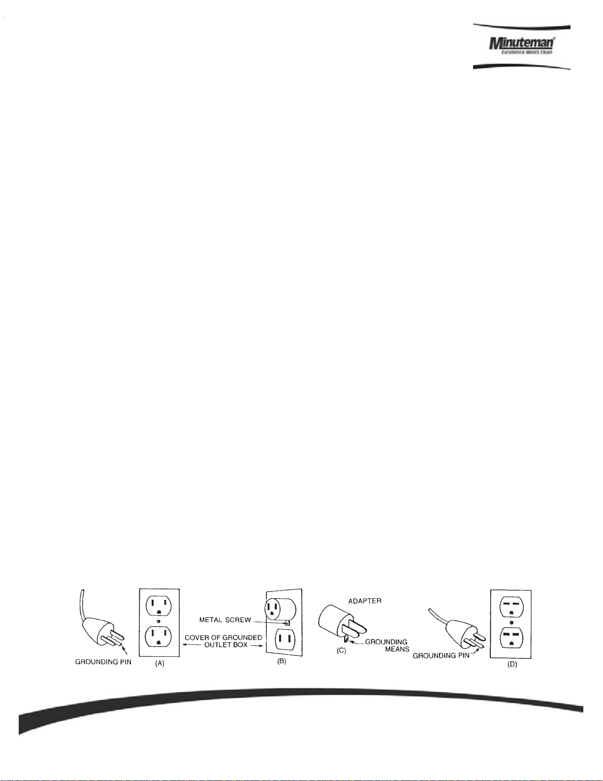
Grounding Instructions
• This floor finishing machine should be grounded while in use to protect the operator from electric
shock. The machine is equipped with a three-conductor cord and three prong grounding type
attachment plug to fit the proper grounding type receptacle. The green (green and yellow) conductor
in the cord is the grounding wire. Never connect this wire to anything other than the grounding blade.
• Floor Finishing Machines Rated Less than 150-Volt s – If the machine is provided with an attachment
plug, as shown in Sketch A, it is intended for use on a 120-V olt (normal) circuit. If a properly grounded
receptacle, as shown in Sketch A, is not available, an adapter as shown in Sketch C, is available and
be installed as shown in Sketch B if the outlet box that houses the receptacle is grounded. Be sure
to fasten the grounding tab with the faceplate screw.
• Floor Finishing Machines Rated More than 150-Volts – If the machine is provided with attachment
plug as shown in Sketch D, it is intended for use in nominal 240-V olt circuit. No adapter is available
for this plug.
Parts an d Instruction Manual
Page 2
Page 6

POUR USAGE COMMERCIAL SEULEMENT
MODE D’EMPLOI SECURITAIRE
Lorsque l’on utilise un appareil électrique, des précautions de base doivent toujours être suivies
telles que:
BIEN LIRE LE MODES D’EMPLOI AVANT USAGE
AVERTISSEMENT
• Ne pas quitter l’appareil lorsque la prise de courant est branchée. Débrancher de la sortie
électrique lorsque la machine n’est pas en usage ou pour en faire le service.
- Pour réduire les risques de feu, choc électrique ou blessure:
AVERTISSEMENT
Pour réduire le risque de choc électrique - Ne pas exposer à la pluie - Entreposer à l’intérieur.
• Ne jamais laisser des enfants ou des adultes inexpérimentés faire fonctionner cet appareil.
• Garder la zone de fonctionnement libre de toute personne, particulièrement les petits enfants
et les animaux. Garder les spectateurs à une distance d’au moins 7,6 mètres (25 pieds) de la
zone de fonctionnement.
• Utiliser tel que prescrit dans le livre d’opération et seulement avec les attachements recommendés
par le manufacturier.
• Ne pas s’en servir avec corde ou prise de courant endommangée. Si l’appareil ne fonctionne
pas ou a été échappé, endommagé, entreposé à l’extérieur ou déposé dans l’eau, l’appareil
devrait être envoyé à un département de service pour inspection.
• Ne pas tirer ou porter par le câble ou se servir du câble comme poignée. Ne pas fermer de
portes sur le câble ou tirer le câble près d’objets pointus. Ne pas conduire l’appareil écrasant le
câble et soyez certain de protéger le câble entre toutes surfaces de chauffage.
• Ne pas débrancher en se servant du câble. Pour débrancher tirer sur la prise et non sur le
câble.
• Ne pas manipuler la prise ou l’appareil avec les mains mouillées.
• Ne placer aucun objet dans la sortie et ne pas s’en servir si la sortie est obstruée. Eliminer toute
poussière, maillon, cheveux ou quoique ce soit qui pourrait réduire le mouvement d’air.
• N’exposer aucun cheveux, vêtement, doigts ou autres aux ouvertures de l’appareil.
• Ne rien ramasser de ce qui brûle ou de fumée tels que cigarettes, allumettes ou cendres en feu.
• Ne pas employer sans filtre de poussière ou autre en position.
• Fermer tous les contrôles après utilisation.
• Soyez très prudent lors du nettoyage d’escaliers.
• Ne pas ramasser de liquide inflammable ou combustible tel que gazoline et ne pas utiliser dans
les endroits ou ces derniers pourraient être présent.
• Brancher dans une prise avec une prise de terre seulement. V oir références pour prise de terre.
CONSERVEZ CES RECOMMANDATIONS
Parts an d Instruction Manual
DE MODE D’EMPLOI
Page 3
Page 7

INSPECTION
Déballer soigneusement en constatant s’il y, a lieu tout dommage apparent. Chacune des pièces
d’équipement est entièrement inspectée à l’usine et tout dommage de transit est la responsabilité de la
compagnie de transport qui devrait être prévenue immediatement.
AVERTISSEMENT
• S.V.P. lire le manuel d’instruction avant d’opérer cette pièce d’équipement.
• Pour réduire le risque d’incendie, se servir de ces appareils uniquement pour usage commercial et
avec les produits contruits spécifiquement pour usage avec ces appareils.
• Les moteurs électriques peuvent être la cause d’explosion si ils sont utilisés près de matériaux ou de
vapeurs explosives. Ne pas opérer près de matériaux inflammables tels que solvant, essence,
poussière de grain etc.
ELECTRICITE - 115 Volt Modèles C8420-115
Ces appareils sont congus pour opérer sur un circuit standard de 15 amp, 120 volt, 60 hz, circuit AC.
T out volt age en bas de 105 volt AC ou au-delà de 125 volt s AC pourrait occasionner des dommages au
moteur.
ELECTRICITE - 240 Volt Modèles C8420-240
Ces appareils sont congus pour opérer sur un circuit standard AC de 16 amp, fusible type L 230 volt, 50
hz. Tout voltage en bas de 200 volt AC ou au-delà de 250 volts AC pourrait occasionner des dommages
au moteur.
INSTRUCTIONS POUR PRISSE DE TERRE
• Ces appareils doivent posséder une prise de miss à terre pour protéger l’opérateur contre les chocs
électriques. Cet appareil est muni d’une corde électrique à trois fils et d’un receptacle à trois fourchons
et prise de mise à terre pour s’accorder dans un receptacle avec prise de mise à terre réciproque. Le
fil conducteur vert (ou vert et jaune) de la corde électrique est le fil designé comme prise de mise à
terra. Ne jamais relier ce fil à un fil autre que celui de prise de mise à terre.
• Appareils estimés à moins de 150 volts - Si ces appareils of frent une prise de courant tel que dans
le croquis A, ils sont destinés pour utilisation avec un circuit de 120 volts. Si un receptacle avec prise
de mise à terre n’est pas disponible tel que montré au croquis A, un adapteur tel que vu au croquis C
est disponible et devrait être installé tel que montré au croquis B si la boite électrique est munie d’une
prise de mise à terre. Assurez-vous de bien relier la patte de prise avec la vis.
• Appareils destinés à plus de 150 volts - Si ces app areils offrent une prise de courant tel que demontré
au croquis D, ils doivent être utilisés avec un circuit de 240 volts. Aucun adapteur n’est disponible
pour cette prise.
Parts an d Instruction Manual
Page 4
Page 8
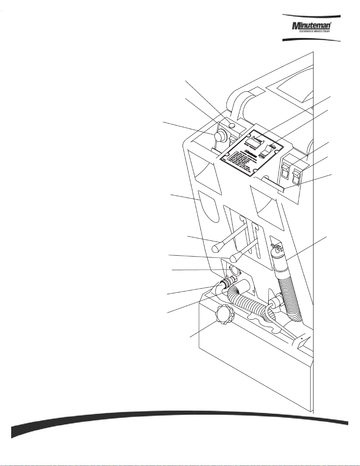
Machine Overview
POWER ON INDICATOR LIGHT
1
MAIN POWER SWITCH
2
WORKING SPEED DIAL
3
120V AC PLUG-IN
4
TRACTION DRIVE LOCK LEVER
5
BRUSH/VAC SHOE RAISE/LOWER LEVER
6
120 VOLT AC AUXILLAR Y TOOL HOOKUP
7
SPRAY JET/AUXILLARY FLOOR TOOL HOOKUP
8
VACUUM SCRUB HEAD HOOKUP
9
BRUSH PRESSURE ADJUSTMENT KNOB
10
BRUSH PRESSURE GAUGE
11
FORWARD/REVERSE SWITCH
12
PUMP SWITCH, AUTOMATIC AND AUXILLARY
13
VACUUM SWITCH
14
TRACTION DRIVE CONTROL LEVERS
15
16
DUMP HOSE
1
2
3
4
11
12
13
14
15
5
16
6
7
8
9
10
Parts an d Instruction Manual
Page 5
Page 9

Operating Instructions
1. Filling: Fill the solution tank with the desired amount of water and add liquid cleaning
solution to the proper dilution ratio. DO NOT USE powdered cleaning chemicals.
Powders are unlikely to dissolve thoroughly, resulting in clogging the inline solution
filter. This can reduce or stop water flow to the pump and spray jets.
2. Connect power supply cord to grounded wall outlet, Item # 4
3. Engage traction drive system, Item #5
4. Turn on main power switch, Item #2
5. Lower scrub head assembly, Item #6
6. Turn on pump switch to automatic, Item #12
7. Turn on vacuum, Item #13
8. Set forward/reverse switch to forward, Item #11
9. Engage traction drive control levers, Item #14
10. Adjust forward speed #3
11. Brush pressure can be adjusted + or – by knob, Item #9, and viewing gauge, Item #10
in green zone
Accessory Attachments
1. Turn master switch off
2. Disconnect vac hose, see item #8, and attach vacuum hose from remote tool.
3. Disconnect solution hose, see item #7, and install remote tool solution hose to the
quick disconnect. Turn the pump solution switch, item #13, to auxiliary.
4. Turn on main power switch.
5. Turn on switch #13 to activate vacuum motor.
Parts an d Instruction Manual
Page 6
Page 10

Exploded Views
T ank Assembly I
Parts an d Instruction Manual
Page 7
Page 11

Tank Assembly I BOM
ITEM PART NO. QTY. DESCRIPTION
1 130029 4 GROMMET .75X.31X.25
2 13011 8 1 STRAINER-SOLUTION
3 210121 1 DUMP HOSE 200 SERIES
4 260184 1 SUPPORT ANGLE
5 260203 1 CLAMP-HOSE 102120 MURRAY
6 320269 1 STRAP, DRAIN PLUG RETAINING
7 320271 1 FITTING-PP 90 3/8MPT 3/8HOSE
8 420013 1 TUBE 1/2 X 3
9 430089 1 FLOAT 17B
11 450081 2 WSR 1.908 X 2.41 X .03 SS
12 710353 2 SCR-MC 10-32 X .37 ZINC
13 710985 6 SC 3/8-16 X .62
14 711118 14 SCR-ST-A 10 X .75 SS
15 712092 1 SCR 1/4-20 X 2.5 NYL
16 712107 2 SCR-SHOULDER 1/4-20x2.87
17 712563 4 SCR-MC 1/4-20 X 1.00 SS
18 712568 1 SCR-MC 1/4-20 X 2.25 SS
19 712667 5 NUT-HEX NYLOC 1/4-20 SS
20 712683 16 NUT-HEX NYLOC 5/16-18 SS
21 712759 2 WSR-FLT .31 X 1.37 X .06 SS
22 712767 26 WSR-FLT .406 X .75 SS
23 715840 1 DECAL - AMBASSADOR 20
24 762384 2 BUSHING-.277 X .375 X .37 SS
25 828970 2 WSR NEOP 1.87X2.4X.125
26 831812 2 FITTING ABS 1.5MPT 1.5HOSE
27 832896 2 WHEEL-GUIDE
28 832949 2 BRACKET BUMPER
29 833160 1 ADAPTER, PVC 1.5 FPT X 1.5 SLI
30 833254 2 BUMPER WHEEL AXLE
31 833316 1 DRAIN PLUG
32 840001 1 LID TANK AMB 20 BURGUNDY
33 840002-1 1 SOLUTION TANK AMB 20 - BURGUNDY
34 840017 1 DOME AIR / WATER
35 840051 1 BLADDER BAG
36 840054 2 ANGLE, BLADDER SIDE
37 840055 2 ANGLE, BLADDER TOP/BOT
38 840061 1 GASKET, DOME
39 840063 1 FRAME BLADDER MOUNT
40 840069 1 POCKET GASKET
41 840070 1 WASHER PLA TE ASSEMBL Y
42 840071 1 GASKET SOL/REC
43 840074 1 VALVE PIVOT BRACKET
44 840075 1 FLOAT VALVE
46 840087 1 COVER PLATE/DOME
47 840095 2 PLUG DOME - HEYCO .312
48 840104 1 FILTER ASY / VAC MOTOR
49 84011 3 2 SIDE PANEL
50 840119 4 GASKET, LID F/R, PVC FOAM
51 840120 2 GASKET, LID LONG, PVC FOAM
52 840121 2 GASKET, LID SHORT, PVC FOAM
Parts an d Instruction Manual
Page 8
Page 12

T ank Assembly II
Parts an d Instruction Manual
Page 9
Page 13

Tank Assembly II BOM
1 260087 1 HINGE-15" 40 740801 1 SWITCH-ROCKER ON/OFF DPDT
2 260203 1 CLAMP-HOSE 102120 MURRAY 41 740806 2 SWITCH-SNAP ACT 20A 1HP
3 260255 1 SPEED CONTROL BRACKET 260TD 42 741201 1 RECEPTACLE-15A FEMALE SQUARE
4 260291 2 HANDLE GRIP 260TD 43 742145 1 RELAY-MOTOR REVERSE 120V
5 710204 2 SCR-MC 6-32 X .50 ZINC 43A 742146 1 RELAY-MOTOR REVERSE 240V
ITEM PART NO. REQ’D DESCRIPTION ITEM PART NO. REQ’D DESCRIPTION
6 710307 6 SCR-MC 6-32 X 1 ZINC 44 760592 2 KNOB-OVAL TAPERED
Parts an d Instruction Manual
7 711160 14 SCR-HI/LO #10 X 5/8 ZINC 45 762295 2 BUSHING-ADJ .375 X .62 X .18 Z
8 711322 1 NUT-HEX 5/16-24 ST PL 46 762331 2 WHEEL,2.5DX1.28W X.38ID
9 711372 2 NUT-NYLOC 8-32 47 802657 4 SILCONE BOOT /CARLING SW
10 711430 3 NUT-TINNERMAN 6-32 48 809754 1 SWITCH-ROCKER
11 711506 2 WSR-FLT 5/16 (NARROW) ST PL 49 809874 1 KNOB-SPEED CONTROL
12 711523 2 WSR-WAVE .37 X .68 X .08 50 828370 1 BH2-60 FEMALE COUPLER
13 711577 4 WSR-FLT .260 X .50 X .020 51 828952 1 FITTING PP 1/4MPT 3/8BARB
14 711578 1 WSR-FLT 1/2 BRS 52 741205-1 1 CORD ASY, 14/3 75' GFCI-FEM LOCK PLUG
15 711717 2 RET RING-E EXT .37 52A 740477-2 1 CORD ASY-EURO 250V 50FT BLACK
16 711808 2 PIN-HAIRPIN COTTER #13 53 830540 1 RECEPTACLE-FLG MALE 15 A 125
17 712516 2 SC 8-32 X .62 SS 54 832859-1 1 INDICATOR LIGHT 115V ASY
18 712537 6 SCR-TR HD 10-24 X .75 SS 54A 832860-1 1 INDICATOR LIGHT ASY 240V
19 712540 10 SCR-MC 10-24 X .37 SS TH 55 833102 1 SPRING-KNOB .60 X .73 X 1.75 Z
20 712560 13 SCR-MC 1/4-20 X .50 SS NYL 56 833329SA 1 SWITCH-STAGERED ACTION
21 713005 6 BLT-HH 1/4-20 X 1.5 SS 57 840005-1 1 BASE TANK AMB 20
22 711373 2 NU T,NYLON 14/20 ZINC 58 840013 1 PLATE LEVER SWITCH
23 712638 2 NUT HEX 10-24 SS NYLOC 59 840014 1 LEVER CONTROL BOX
24 712665 2 NUT-HEX 1/4-20 SS 60 840022 1 LEVER BAR ASY BELT TNSN
25 712759 6 WSR-FLT .31 X 1.37 X .06 SS 61 840023 1 LEVER BAR ASY VAC SHOE
26 712761 6 WSR-FLT .28 X 1.25 X .059 SS 62 840024 2 LEVER - SWITCH
27 712811 2 SCR-MC 10-24 X .50 ZINC 63 840027 1 HOSE CLIP
28 712813 2 SCR-MC 10-24 X .75 ZINC 64 840039 1 LEVER PIVOT PIN
29 713048 2 BLT-HH 3/8-16 X 2.50 #5 65 840040 2 BUSHING-LEVER BOX .396 X .625
30 715383 2 DECAL, MINUTEMAN 66 840057 1 PLATE, SWITCH
31 715621 1 DECAL-VAC/PUMP 67 840079-1 1 AUXILIARY PLATE ASY
32 715622 1 DECAL-DASHBOARD 68 840080 1 DASH PANEL
33 715623 1 DECAL-BRUSH/TRACK LIFT 69 840091 1 CABLE-LIFT
34 715626 1 DECAL-SPEED CONTROL 70 840092 1 CABLE-TENSION
35 740187 1 CONTROLLER-2SP 115/230V 71 840093 1 YOKE
36 740202 2 RECTIFIER-BRIDGE 50A 600V IMP 72 840097 1 HOSE GRAY WATER
36A 740203 2 RECTIFIER-BRIDGE 50A 1000V 73 840108 1 BRACKET, RELAY
37 740229 1 GAUGE BR PRESSURE 0-1.5 74 840122 1 PLATE - RECEPTACLE
38 740736 2 SWITCH-3 POSITION 75 829214 4 RIVET, 1/8 DIA. REFERENCE POP
39 740738 1 WIRE ASSY . 76 829851 1 RECEPTICLE
39A 740787 1 WIRE ASSY.
Page 10
Page 14

Base Assembly
Parts an d Instruction Manual
Page 11
Page 15

Base Assembly
Parts an d Instruction Manual
Page 12
Page 16

Base Assembly
Parts an d Instruction Manual
Page 13
Page 17

Base Assembly
Parts an d Instruction Manual
Page 14
Page 18

Base Assembly
Parts an d Instruction Manual
Page 15
Page 19

Base Assembly BOM
BILL OF MA TERIAL - 840200-1
1 24109 6 1 HOSE 3 /8 x 45" WIRE REINFORCED, SCV 24/26 50 740747 1 WIRE JUMP ER (NOT SHOW N)
2 26006 6_ 1 BUSHING -FLG, .375 X .50 X .31 51 740872 1 MO TOR - GEAR, AMB 20, 140V D C
3 26018 2 1 HOSE 3 /8 x 24" WIR E REINFORCED 52 760251 2 CASTER WH EEL, 3" DIA. X 2" WIDE
4 26020 3 1 WIRE G RIP HOS E CLAM P 53 760859 2 CLAM P , HOSE
5 29001 7 1 VAC M OT O R G ASKET 54 762073 3 BU SH ING .259 X .375 X .265
6 36123 3 3 KEY, 3/16 SQ. X 1.50" 55 762422 2 SPRING, COMP RESSIO N
7 38006 4 1 RING, FOAM 56 805634 1 COVER BOX (741012)
8 430051 1 RETURN SPRING -3.00" 57 809148 2 RET AINING RING -"E" T YPE, EXT ., 3/4"
9 45000 4 1 AIR M ANIFOLD 58 809 226 2 WASHER, FLAT - .40 X 1.50 X .12
10 450023 1 SPRAY BAR ASSEMBLY ACS 59 809 311 1 PIN-COTTER 7/64 DIA X 1
11 450050 3 HEYCO 3231 NPT HUB - BLACK 60 809880 2 BUSHING .259 X .375 X .265
12 45005 9 1 FITTING 1/4MPT BRASS BULKHEAD 61 828 368 1 MALE COUPLER
13 450076 2 CLAMP-CRIM P 185R SS 62 828 952 2 FIT T ING PP 1/4" MPT X 3/8" HOSE BARB
14 710154 2 SCR-MC TR HD 10-32 X .625 SS 63 829129 2 CLAMP-HOSE, WORM -DRIVE FOR 8-22MM HO SE DIA.
15 71020 7 2 SCR -MC 6-32 X .87 Z INC 64 831306 1 FITTING 90 ST REE T BRASS 1/4x1 /4
16 710986 2 SCR -SC 3/8-16 X 1.0 ST PL 65 831965 2 3/8 x 1.63" CLEVIS PIN
17 71112 4 6 PAN H EAD ST #10 X .37 NI 66 832790 1 HOSE VAC TAN K
18 71116 0 19 #10 X 5/8 HI-LO 67 833067 1 PUMP-100PSI 115 V
19 71120 2 4 BLT -HH 1/4-20 X 0.5 0 STPL 68 8 33302 1 DIE SPRING
20 71120 6 4 BLT-HH 1/4-20 X .87 STL ZINC 69 833 325 1 FITTING N YLON 90 1/4MPT X 3/8 HB
21 71121 4 1 BLT-HH 1/4-20 X 2.0 0 70 83334 1-1 2 BLT-EYE 3/8-16 X 2.62
22 71128 0 1 BLT -HH 3/8-16 X 3.5 0 #5 71 833 374 2 PIN , HAIRPIN CO TT E R 3/8
23 711371 2 N U T-NYLOC 6-32 STL ZINC 72 840006-1 1 F R AME WELDMENT
24 711375 1 NUT- NYLON LOCK, 3/8-16 HALF NUT 73 840011 1 VAC MO TOR COVER, T OP
25 71138 0 3 NU T -NYLO C 3/8-16 NUT 74 840012 1 VAC M OT OR COVER, BOTTO M
26 71140 0 3 NUT -PIPE LO C K 1/2" 7 5 8 40018 2 WASHER PLAT E
27 71150 4 16 WSR -F LAT 1/4 ID SS 76 840 042 1 H OSE, VAC MOTO R OU TPUT
28 711505 9 1/4 FL AT WASHER , ST EEL 77 840 044 1 PULLEY, IDLER
29 711506 2 WSR -FLT .344 X .690 X .062, STEEL 78 840049_ BASE 2 BEARING BASE
30 71150 7 6 WSR-F LAT .37 X 1.12 X .06 79 84 0049_C AP 2 BEARING CAP
31 71151 2 2 WSR-FLAT .75X1.37X.08 80 840060 1 B RUSH MOUNT ASSY
32 71151 5 2 WSR-FLAT .406 X .812 X .0 625 81 84006 4-1 1 BR ACKET - PUMP MOTO R
33 71151 9 2 WSR- F LAT .25 X 1.01 X .06 82 8 40 082 1 HOSE 3/8 x 24 " WIRE REINFOR CED
34 71154 5 4 WSR-HE LICAL 5/16 83 840 088 1 PU L LEY - V BELT
35 71231 0 1 WSR- FLAT .5 2 X .87 X .06 PL 84 840089 1 BAFFLE, EXHAUST
36 712345 3 SCR - TO RX PAN HEAD, 1/4-20 X 1.50 85 840 090 1 C OVER, EXHAUST BAFFL E
37 712537 4 10-24 X .75 SS TRUSS H D SC R 86 840 092 1 T EN SION C ABLE
38 712540 10 SC R-MC T R H D 10-24 X .37 SS 87 8 40 096 1 F ILTER, EXHAUST BAFFLE
39 71256 2 8 BO LT -HH 1/4-20X3/4 SS 88 840 105 1 COVER-DRIVE MOTOR
40 712575 4 BLT-HH 5/16-1 8 X .7 5 SS 89 840114 1 SPACER, STEEL
41 712665 3 N U T-H EX 1/4-20 SS 90 840115 1 DIFFERENTIAL
42 71266 7 8 NU T , HEX 1/4-20 NYLOC S S 91 840 116 2 WH EEL, 8" X 1 .5" W/ .75 ID
43 712695 4 NUT-HEX 3/8-16 SS 92 8 40 141 3 SPACER - STEEL, .688 O D X .265 ID
44 71275 8 8 WSR-HE LICAL 1/4 SS 93 8 40 144 1 D RIVE BELT - AM B. 20, 1/2" X 27"
45 712767 4 FLAT W ASHER .406 ID X .75 O D X . 94 8 40 151 1 TENSION ARM WELDM ENT
46 71304 9 2 BLT-HH 3/8-16 X 2.75 #5 95 840 153 1 TENSION PLATE WELDM ENT - AMB 20
47 74008 9 1 VAC M OTOR 3 - STAGE 120V 96 8 81059 2 BEARING, .75" W/COLLAR
48 74018 9 1 TER MINAL BLOCK 10 471 97 833265PLT 3 THR EADED SPACER ZINC PLT
ITEM PART NO. REQ'D DESCRIPTION ITEM PART NO. REQ'D DESCRIPTION
49 74024 5 1 SO LENOID-WAT ER 11 5V
Parts an d Instruction Manual
Page 16
Page 20

Brush Assembly
Parts an d Instruction Manual
Page 17
Page 21

Brush Assembly BOM
ITEM PART NO. REQ’D DESCRIPTION
1 670669 1 CLAMP-P 3/8 ID
2 700287 1 GROMMET
3 710923 2 SC 5/16-18 X .62 ZINC
4 711018 2 SK 10-32 X .37
5 711160 5 SCR-HI/LO #10 X 5/8 ZINC
6 711232 2 BLT-HH 5/16-18 X 1.50
7 711350 2 NUT-NYLOC 10-32
8 711353 2 NUT-ACORN 5/16-18 ST PL
9 711391 1 NUT-HEX JAM 3/8-16 ST PL
10 711504 2 WSR-FLT 1/4 SS
11 7 11539 1 WSR-EXT LOCK 3/8
12 711554 11 WSR-INT LOCK 1/4
13 711558 2 WSR-INT LOCK 5/16
14 71 1717 1 RET RING-E EXT .37
15 712066 12 SCR-ST-PAN HD-AB 10 X 1.25 ZIN
16 712081 2 BLT-SHOULDER 5/16-18 X .75 X .
17 712318 2 WSR-FLT .75 X 1.12 X .12 PL
18 712536 3 SCR-MC 10-24 X .62 SS
19 712560 11 SCR-MC 1/4-20 X .50 SS NYL
20 712638 3 NUT HEX 10-24 SS NYLOC
21 712757 12 WSR-HELICAL #10 SS
22 715090 1 DECAL-BRUSH PRESSURE
23 740740 1 MOTOR BRUSH 120VDC
23A 740785 1 MOTOR BRUSH 240VDC
24 740739 1 CORD ASSY
25 760034 1 KNOB-ADJ 3/8-16 THREAD
26 760035 1 BEARING-FLG MOUNTED
27 827894 2 CUP BEARING
28 827896 2 COVER BEARING
29 827903 4 WAVE WASHER
30 828145 2 RET RING
31 828588 2 BEARING-.500 X 1.125 X .312
32 832903 1 BR PULLEY 3-40GR 5MM
33 833281 1 THREADED ROD ADJ SS
34 833326 1 VAC TUBE
35 833342 1 SHAFT PIVOT SS
36 833357 1 PULLEY MTR 20TOOTH 5MM
37 833376 1 BELT-HTD 375-5M-09
38 840007-1 1 VAC SHOE PLTE 12SS
39 840019 1 BRUSH BRACKET
40 840052 1 BRUSH
41 840062-1 1 VAC SHOE 20"
42 840065 1 COVER-BRUSH SPLASH
43 840081 1 AXLE
44 711106 6 SCR - #10-24 X .75, TYPE A
Parts an d Instruction Manual
Page 18
Page 22

Trouble Shooting Guide
Use this guide to pinpoint problem areas that may arise with the use of your Ambassador 20.
CAUTION! Unplug supply cord before servicing machine components.
Solution System
I. No water dispensed from spray jets
A. The hose connection at the pump for the spray tube may not be tight. Disconnect, then
reconnect the fitting, to ensure the fittings snap together securely.
B. The solution pump diaphragm may be damaged. Inspect by removing the diaphragm
from the pump and inspect the diaphragm for cracks. Replace if required.
II. Spray intermittent or streaked
A. Solution hoses may be clogged. Replaced kinked hoses if found.
B. The filter strainer in the solution tank may be clogged. Clean the strainer thoroughly.
C. The spray jets may be clogged. Remove the end plug from the spray tube and flush by
turning the pump on. Remove the spray jets from the tube and clean as required. Do
not clean out the hole in the jet with a pin or wire. This may cause permanent streaking.
Solution Recovery
I. Solution recovery is reduced.
A. Vacuum filter maybe clogged. First check filter recovery tank. Clean if required.
B. Check the vacuum hoses for secure fit over the vacuum fittings. Tighten clamps where
used. Also check hoses for cracks, kinks or clogging.
C. Check the seals on the tank covers for damage. Replace if needed. Make sure cover
closes freely without restrictions.
D. Make sure the drain hose on the back of the tank is sealed.
E. Check the vacuum slot on the scrub head for clogging. Clean out the slot if required.
F. Vacuum motor brushes could be worn. Inspect and replace. If motor has run through
two sets of brushes, replace the motor.
Parts an d Instruction Manual
Page 19
Page 23

Electrical System A.C.
Solution Recovery (cont’d)
II. Pump motor does not run.
A. Check pressure switch for short circuit. By-pass the pressure switch by connecting
the two black leads to the switch to one another, if the motor then runs, replace the
pressure switch.
III. Machine fails to run when handle switch is activated.
A. Speed control maybe shorted out.
B. Speed control potentiometer may be defective.
I. Vacuum motor does not start.
A. Inspect the micro switch lever inside the electrical enclosure to make sure it is
functioning properly. As the scrub head is lowered the lever should activate
the switch. Bend the switch lever to adjust function if required.
B. Check motor carbon brush.
C. Check plugs on power cord.
FOR ALL THE ABOVE MAKE SURE ALL THE ELECTRICAL CONNECTIONS ARE SECURE. MAKE SURE THE CORD
TO THE W ALL OUTLET IS SECURE. MAKE SURE THE GFCI IS NOT TRIPPED IF THE UNIT IS EQUIPPED WITH ONE
(LOCATED ON POWER CORD).
Parts an d Instruction Manual
Page 20
Page 24

Wiring Diagram
Page 25

~-----------+------------_,7~~~--------------------------------------------------------------------------_J
J~r~--------------------------------------------------------------r'~
L-_
120V
POWER
240V
120VAC
240VAC
POWER
RECEPTACLE
741203
IN
IN
RECEPTACLE
830540
~1----------,
POWER
741205-1
740477-2
CORD
120VAC
240VAC
GFCI
PROTECTED
ON
CORD
~
GND
-
) )
~--~~~~~~~~~~~~]1
1--------IJ.:~I-----.,
r-----
~.......,,___
GROUND
STUD
-.!-
GND
I
~z
n
~~
~
~m ~i
~
--
CONTROu.ER l \ "
7<40187
I__
--------
RESIST.
"""' s
4
2JR
___
L..
~
~ ~
_J
UOTOR
_ _
7407D7
BLACK
7~~
BRIDGE
RECTIFIER
740202
7<40203
;!
(120V)
(240'¥)
~~
--
-,
MOTOR
B 9
MACHINE
GROUND-ATIACHED
TO
FRAME
745088
L____________________
Rev
B
L__ _ ___J
(\
"""""""
~=~
~~
c:::C
~8
--------
IT
---------
'
¥!1~
~:0~~
:::J=>
8 8
8©
I
-------------------
POWER
PANEL
_____J\,_
____
7<f.0747
WHITE
WHITE
_,.,.LAO<,..,_--;f:=
PUIIIP
f~::l
,/;,
SOLENOID
7~0245
7<402<40
BLAO<
~
(12011)
(240'¥) -
AMB20 2 OF
2
Page 26

Minuteman International Made Simple Commercial Limited Warranty
REVISION F
EFFECTIVE 6/1/2009
Minuteman International, Inc. warrants to the original purchaser/user that the product is free from defects in workmanship and materials under
normal use. Minuteman will, at its option, repair or replace without charge, parts that fail under normal use and service when operated and
maintained in accordance with the applicable operation and instruction manuals. All warranty claims must be submitted through and approved
by factory authorized repair stations.
This warranty does not apply to normal wear, or to items whose life is dependent on their use and care, such as belts, cords, switches, hoses,
rubber parts, electrical motor components or adjustments. Parts manufactured by Minuteman are covered by and subject to the warranties
and/or guarantees of their manufacturers. Please contact Minuteman for procedures in warranty claims against these manufacturers.
Special warning to purchaser — Use of replacement filters and/or prefilters not manufactured by Minuteman or its designated licensees, will
void all warranties expressed or implied. A potential health hazard exists without original equipment replacement.
All warranted items become the sole property of Minuteman or its original manufacturer, whichever the case may be.
Minuteman disclaims any implied warranty, including the warranty of merchantability and the warranty of fitness for a particular purpose.
Minuteman assumes no responsibility for any special, incidental or consequential damages.
This limited warranty is applicable only in the U.S.A. and Canada, and is extended only to the original user/purchaser of this product.
Customers outside the U.S.A. and Canada should contact their local distributor for export warranty policies. Minuteman is not responsible for
costs or repairs performed by persons other than those specifically authorized by Minuteman. This warranty does not apply to damage from
transportation, alterations by unauthorized persons, misuse or abuse of the equipment, use of non-compatible chemicals, or damage to
property, or loss of income due to malfunctions of the product.
If a difficulty develops with this machine, you should contact the dealer from whom it was purchased.
This warranty gives you specific legal rights, and you may have other rights which vary from state to state. Some states do not allow the
exclusion or limitation of special, incidental or consequential damages, or limitations on how long an implied warranty lasts, so the above
exclusions and limitations may not apply to you.
Cord Electric Group: Three years parts, two years labor, ninety days travel (Not to exceed two hours)
Exceptions……….
Model Parts Labor Poly Travel
Port A Scrub 1yr 6months 10yrs 0
MPV 13 1yr 0 0 0
MPV 14 & 18 2yrs 1yr 0 0
V Series Upright Vacuums 1yr 1yr 0 0
Rapid Air Blower 1yr 1yr 10yrs 0
Explosion Proof Vacuum 1yr 1yr 0 0
X12, X12H & TRS 14 1yr 1yr 10yrs 0
E17 & E20 Electric Scrubbers 1yr 6month 10yrs 0
Pneumatic Vacuums 3yr 1yr 0 0
Description Parts Labor Poly Travel
Battery Operated Group 3yrs 2yrs 10 90 days
Sweepers 1yr 1yr 10 90 days
Internal Combustion Group 1yr 1yr 10 90 days
Not to exceed two hours
Exception: PAS 14B 1yr 1yr 10yr 0
Battery Chargers: One year replacement
Replacement Parts: Ninety days
Batteries: 0-3 months replacement, 4-12 months pro-rate
Polyethylene Plastic Tanks: Tanks have 10yr warranty, no additional labor
14N845 U.S. Route 20, Pingree Grove, IL 60140 USA
Phone (800) 323-9420 - www.minutemanintl.com
A Member of the Hako Group
988403
Rev F 05/11
 Loading...