

C80115-01,C80115-02,C80115-03,C80115-04,C80130-01,C80130-02,C80155-01,C80155-02,C80215-01,C80215-02,C80215-03,C80215-04
Minuteman C80115-04, C80115-01,C80115-02,C80115-03,C80115-04,C80130-01,C80130-02,C80155-01,C80155-02,C80215-01,C80215-02,C80215-03,C80215-04, C80115-01, C80130-01, C80130-02 Operation Service Parts Care
...Page 1
X-1000 &
Model:
MX-1000
Vacuum
Series
OPERATION
C80115-01,02,03,04
C80130-01,02
C80155-01,02
C80215-01,02,03,04
SERVICE PARTS
CARE
Revised 1/94
Page 2
OPERATING INSTRUCTIONS
INSPECTION
Carefully unpack and inspect your machine for shipping damage. Each unit is tested and thoroughly inspected before
shipment, and any damage is the responsibility of the delivering carrier who should be notified immediately. Read all
instructions carefully before operating.
WARNING
Model (X-1000) Dry Pickup Only, C80115-01, 02, 03, 04, C80130-01, 02, C80155-01, 02
Electrical shock could occur if used on wet surfaces. Do not expose to rain. Store indoors.
Electrical motors can cause explosions when operated near explosive materials or vapors. Do not operate this machine
near flammable materials such as solvents, thinners, fuels, grain dust, etc.
WARNING
Model (MX-1000) Wet & Dry Pickup, C80215-01, 02, 03, 04
To avoid electric shock, do not expose to rain. Store indoors.
CAUTION
Hazardous materials must be disposed of properly. Never throw contaminated debris in your usual trash receptacle.
Place debris in a plastic bag or can marked “ HAZARDOUS MATERIALS” and take to a hazardous waste handler.
ELECTRICAL
This machine is designed to operate on a standard 15 amp. 115 volt, 60 hz, AC circuit. Voltages below 105 volts AC or
above 125 volts AC could cause serious damage to the motor.
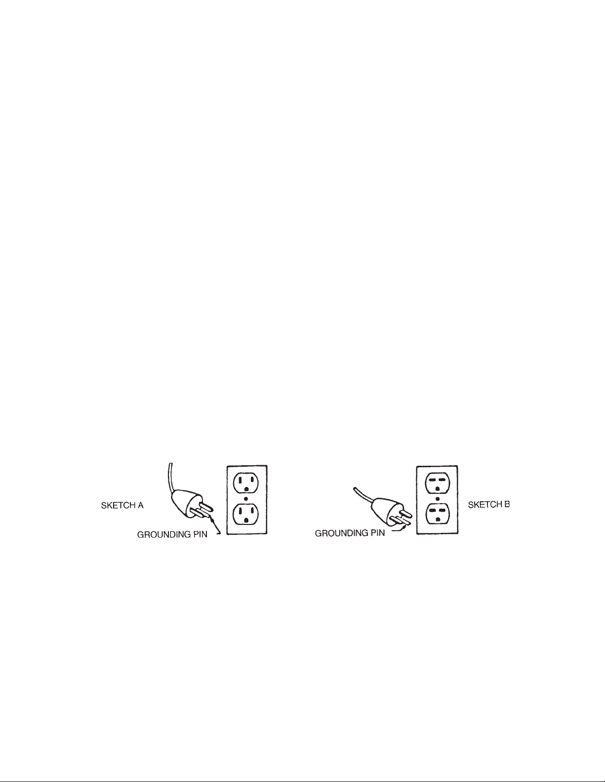
GROUNDING INSTRUCTIONS
To protect the operator from electrical shock, this machine must be grounded while in use. This machine is equipped
with an approved three-conductor power cord and grounding type plug to fit the proper grounding type receptacle.
This machine is for use on a nominal 120 volt circuit and has a grounding plug that looks like the plug illustrated in
sketch A. Make sure that the machine is connected to an outlet having the same configuration as the plug. No adapter
should be used with this machine.
For equipment rated 150-250 volts: If the machine is provided with an attachment plug as shown in sketch B, it is
intended for use on a 240 volt (nominal) circuit. No adapter is available for this plug.
EXTENSION CORDS
If an extension cord is used, the wire size must be at least one size larger than the power cord on the machine and must
be limited to 25 feet in length. Extension cord must be three-wire grounded.
MAINTENANCE AND USAGE
Keep the motor intake cooling air screen clean. If this screen (on top of the motor) becomes clogged, it restricts the
flow of cooling air to the motor and will cause overheating.
No lubrication of the motor is required. Machine is equipped with sealed bearings.
For optimum performance, empty and clean filter bag regularly. A clogged and dirty bag restricts the flow of air and
results in reduced vacuum.
Check carbon brush periodically. Replace when worn down to approximately 1/2" in length.
Always unplug the machine when removing the motor head off the tank. This will prevent the accidental starting of the
motor and the possibility of fingers or objects getting into the unprotected impeller intake.
1
Page 3

OPERATING AND FILTER CARE INSTRUCTIONS
The Minuteman Model X-1000 Critical Filter Vacuum has been designed to clean up hazardous and toxic dust of all
types. A special High Efficiency Particulate Air (H.E.P.A.) filter and a series of “prefilters” used with this vacuum reduce
the incidence of airborne dust that would be created by any other method of cleaning.
During the removal of hazardous toxic dust, do not sweep, scoop, shovel, or in any manner handle other than vacuuming.
Do not at any time attempt to bypass, remove, substitute, or by any other means change the filters recommended for
use with this vacuum. Use only approved Minuteman filters and filter bags.
Do not at any time, or in any way, attempt to clean or remove dust particles that may collect or accumulate on the
surface of the H.E.P.A. filter media.
Do not reverse or attempt to clean “prefilters” which have accumulated dust, for the purpose of reusing them.
Since each facility has its own individual and unique cleaning problems, it is suggested that you use the following
guidelines in determining the length of time between filter changes and/or tank emptying:
1. Empty tank after accumulating about 20 pounds of debris.
2. Replace all prefilters each time you empty tank or replace collector bag. In “white room” applications where the
primary objective is to contain non-toxic dust, the “impact” prefilter should be visually checked to determine replacement need. Impact prefilter should be changed when they show dust accumulation.
The efficiency of your vacuum will be determined by the amount and the density of the material you are vacuuming. All
vacuums will lose efficiency as they become filled. The operator must, therefore, be the one to determine the frequency
for emptying and changing filters based on the efficiency and performance of the vacuum during the cleaning process.
The Model X-1000-15 vacuum lid assembly is equipped with a motor cooling air recirculating tube to prevent carbon dust
particles, generated within the motor assembly, from being exhausted out of the machine. The recirculating tube directs
the motor cooling air into the vacuum tank and through the prefilter and H.E.P.A. filter before it is exhausted into the
atmosphere. The recirculating tube requires a small amount of vacuum air flow to operate effectively which may result
in a slightly reduced vacuum performance. If you are not operating under “clean room” conditions that would require the
use of this device, you may disconnect it by simply removing the curved tube on the vacuum lid assembly and plugging
the hole/tube in the lid. Do not plug the hole/tube that is in the side of the dome.
TANK/FILTER SET-UP PROCEDURE FOR MODEL X-1000-15
1. Remove vacuum lid assembly from tank.
2. Install impaction prefilter No. 9, Page 5.
3. Place cloth filter bag onto and into tank using formed rubber gasket as a guide and press down firmly onto the tank
rim.
4. Position vacuum lid onto the tank, making sure that gasket of the lid is seated onto the rubber ring of the cloth bag
frame completely around tank.
5. Snap lid latches into place.
OPTION:
A. A disposable “filter bag protector”, No. 5, Page 17, can be used in the tank, installed ahead of the cloth filter bag.
The filter bag protector is inserted into the tank with the elastic band snapped around the rim of the tank. (About 2
inches of the bag should be outside the tank, then proceed with step 3 above.)
B. Intake down tube, see No. 14, Page 9, with disposable collector bag. If your tank assembly has this option, install
disposable bag by locating the cardboard collar around the intake tube and gently work it up past the raised ring
that runs around the tube, then proceed with step 3 above.
2
Page 4

PROCEDURE FOR REMOVING FILTERS AND FOR CLEANING OUT TANK
Model X-1000-15 Dry only when used for white room applications with non-hazardous materials
1. Unplug machine from power source.
2. Remove vacuum lid/motor assembly with H.E.P.A. filter. Inspect impaction prefilter No. 9, Page 5. If impaction filter
shows discoloration due to dust penetration, replace it with clean filter.
3. Remove cloth filter bag assembly No. 6, Page 17. Clean outside surface of filter bag by shaking in waste container
outside of white room. If another vacuum is available, use vacuum to clean bag.
4. If “optional” filter bag protector No. 5, Page 17, has been used, remove from tank and dispose.
5. Dispose of debris in tank assembly.
6. If “optional” tank with “intake down tube” No. 14, Page 9, has been used, remove disposal collector bag at bottom
of tube and dispose.
7. For proper assembly of new filters, see “Tank/Filter Set-up Procedure”, Page 2.
PROCEDURE FOR REMOVING CONTAMINATED FILTER AND
FOR CLEANING OF CONTAMINATED TANK
Model X-1000-15 Dry only when used for recovery of hazardous or toxic materials
For the protection of your health, you should always wear the proper approved or required face mask,
gloves and clothing as specified by your Safety Department for your particular application.
1. Unplug machine from power source.
2. Remove vacuum lid/motor assembly with H.E.P.A. filter.
3. Remove impaction prefilter, No. 9, Page 5, and place in proper hazardous waste disposal container.
4. Gently remove the cloth filter bag assembly; recommended method of cleaning is by vacuuming with another
H.E.P.A. vacuum.
5. Remove filter bag protector and place in hazardous waste disposal container. “Filter bag protector” is optional, No.
5, Page 17, however, it is recommended in all applications where hazardous, toxic materials are being recovered.
6. Dispose of debris in tank assembly.
7. If “optional” tank with “down intake tube”, No. 14, Page 9, has been used, remove disposable collector bag at
bottom of tube and dispose in proper container.
8. For proper assembly of new filters, see “Tank/Filter Set-up Procedure”.
9. CAUTION: Hazardous materials, including disposable filters and prefilters must be disposed of properly.
10. Never throw contaminated debris in your usual trash receptacle. Place debris in proper containers as
recommended by your Safety Department. All vacuum units should be properly tagged or labeled
“HAZARDOUS MATERIAL” and should only be used by authorized, trained personnel.
ASSEMBLY PROCEDURE 1
Model MX-1000-15 Dry only when used for recovery of hazardous or toxic materials
(see Schematic Fig. 1 on Page 17 for assembly)
1. Install No. 3 spacer gasket onto tank using formed rubber gasket as a guide.
2. Install No. 2 heavy-duty 20 gallon plastic bag liner into tank and drape about two inches over rim of spacer gasket.
3. Place No. 4, 1 to 1 adapter with hose intake, onto tank assembly. Center adapter onto spacer gasket and snap lid
latches into place.
4. Take the proper filter protector bag No. 5 and insert it into adapter. Then snap the elastic band around the rim of the
adapter. Allow two inches to overlap the adapter rim.
5. Place the cloth filter bag No. 6 onto and into the adapter, using the formed rubber gasket to center it.
6. Position the vacuum lid assembly No. 7 onto the adapter, making sure that the gasket of the lid is seated onto the
rubber ring of the cloth bag frame completely around the tank. Snap lid latches into place.
7. Install the tank plug No. 9 into hose intake on tank. All debris picked up through hose intake on 1 to 1
adapter will be deposited into bag liner No. 2 in tank assembly.
PROCEDURE FOR REMOVING DEBRIS
AND CHANGING FILTERS ON MODEL MX-1000-15 ABOVE
1. Remove the vacuum lid assembly and place on worktable.
2. Carefully remove cloth filter bag without disturbing paper filter protector.
3. Reach into bottom of filter protector; pull protector up while gathering together. Remove elastic band around
adapter rim and insert filter protector into plastic bag liner in lower tank assembly.
3
Page 5

4. Use damp disposable towels and wipe down inside of 1 to 1 adapter. Place wipers into plastic bag liner.
5. Unclamp lid latches and remove 1 to 1 adapter.
6. Unclamp holder on underside of H.E.P.A. filter, remove impaction filter and place in plastic bag liner.
7. Collect plastic bag liner from tank rim and tie closed.
8. Remove spacer gasket.
9. Carefully remove plastic bag liner from tank. Do not lift bag out. Turn tank assembly until it is horizontal with floor.
Slide bag liner out, avoiding intake deflector on inside.
10. Dispose of bag liner with debris in accordance with required procedures.
11. For proper assembly of new filters see “Assembly Procedure I - Model MX-1000-15 Dry only” on Page 17.
ASSEMBLY PROCEDURE II
Model MX-1000-15 wet vacuuming only when for recovery of liquid hazardous materials (see Schematic Fig. 2 on Page
17)
1. Install No. 8 water shut-off assembly into tank assembly, centering rubber gasket around rim of tank.
2. Place No. 10, 1 to 1 adapter onto tank, center, and snap lid latches into place.
3. Take the paper filter protector bag No. 5 and insert it into the adapter, then snap the elastic band around the rim of
the adapter. Allow 2 inches to overlap the adapter rim.
4. Place the cloth filter bag No. 6 onto and into the adapter, using the formed rubber gasket to center it.
5. Position the vacuum lid assembly No. 7 onto the adapter making sure that the gasket of the lid is seated onto the
rubber ring of the cloth bag frame completely around the tank. Snap lid latches into place.
6. Water shut-off will activate at approximately 12 gallon level, choking off vacuum.
OPTIONS: Water dump valve can be installed for emptying tank into floor drain. Must be factory installed.
PROCEDURE FOR EMPTYING TANK
1. Remove the vacuum lid assembly and place on work table.
2. Remove and inspect cloth filter bag for moisture. If bag is wet, allow to dry before reusing or replace with clean, dry
filter bag.
3. Remove and inspect filter bag protector for moisture. If bag is wet, replace with dry filter bag protector.
4. Remove 1 to 1 adapter.
5. Remove water shut-off assembly.
6. Dispose of liquid waste in accordance with required procedures.
7. If tank assembly is elevated above container receiving waste, tilt tank on rear wheels by lowering carriage handle
and dump waste into receiving container.
8. If optional dump valve has been installed, lift handle on valve to allow liquid to run out into receiving waste container
or floor drain.
USE OF 30 GALLON OR 55 GALLON ADAPTER
Conversion Options: Wet/Dry Applications
1. Your Model X-1000-15 vacuum can be converted or adapted to fit a 30 gallon or 55 gallon drum when larger
capacity is required.
2. Model X-1000-30 or X-1000-55 can be supplied as original equipment.
3. If you are converting your present X-1000-15 vacuum to 30 or 55 gallon capacity for dry recovery, you will need:
A. 30 or 55 gallon adapter ring, see Page 11.
B. 30 or 55 gallon drum, see Page 13.
C. Drum dolly, see Page 15.
For wet recovery, in addition to the above, you will need:
A. 1 to 1 adapter, see Page 17, No. 4.
B. Water shut-off, see Page 17, No. 8.
4. For proper assembly of new filters, follow “Tank/Filter Set-Up Procedure” on Page 3, supplementing adapter ring
and drum in place of regular tank assembly.
5. For dry recovery, use 30 gallon or 55 gallon heavy-duty drum liner draped over rim of drum before putting adapter
on drum. All material recovered will go into bag liner which can then be removed and replaced as required.
6. For wet recovery, 30 or 55 gallon drum can be equipped with dump valve, see No. 2, Page 13.
7. For wet recovery, install water shut-off assembly onto and into adapter ring and follow steps 2, 3, 4, and 5 as
outlined under Assembly Procedure II. Model MX-1000-15 Wet recovery only on Page 4.
4
Page 6

5
Page 7

Parts List
Item Part No. Qty. Description
1 101040PLT 1 Dome Motor
2 101010PTD 1 Cover, Air Exhaust
2a 750005 1 Exhaust Air Cover
3 101006PTD 1 Inter Vent Dome
3a 750007 1 Inter Vent Dome Assy.
4 480042MCH 1 Cast Motor Hold Down MCH
5 831524 1 Motor, 115V
5a 831526 1 Motor, 220V
6 480060 1 Casting, Lid Polished
6a 750640 1 Assy. Lid Cast Sub.
7 110003 1 Filter Mounting Plate
8 110001 1 H.E.P.A.
9 703007PKG 1 Impact Filter, Pkg. of 12
10 760013 1 Retainer Screen
11 750011 1 Filter Retainer Assy. Includes 10
12 381020 1 Cord Set, 16-3 50 Feet
13 101018 1 Assy. Cord M100
14 711515 1 WSR, Orifice
15 101030 3 Bracket
16 380002 1 Switch, Toggle 1.5 HP
17 101019 1 Switch Box
18 101020 1 Plate, Off/On Indicator
19 807297 4 Brush, Carbon
20 101033 1 Insulation, Foam 3 x 15 x 1
22 101007 1 Insulation, Foam Rub. 1 x 2.50 x 23
23 101009 1 Gasket, Rub. .25 x .56 x 28
24 101005 4 Gasket, Rub. .75 x 3.19 x 4.37
25 480049 4 Gasket Motor
26 480052 1 Gasket, .25 x .87 x .50
27 480040 1 Felt, .25 x 3 x 28
28 828995 2 Motor Gasket
29 480044 1 Felt, Perforated Motor
30 101008 2 Grommet, Rubber
31 100028 2 Strain Relief
32 711401 5 Nut-Riv 10-32
33 760006 3 Ring, Clamp On
34 711202 4 Bolt, 1/4-20 x .50 ST PL
35 711544 4 WSR, Helical SPR LOC 1/4
36 711574 4 WSR, Flat 1” OD x .25 ID
37 710355 3 SCR-MC 10-32 x .50 ST PL
38 710331 8 SCR-MC 8-32 x .75 ST PL
39 710329 8 SCR-MC 8-32 x .50 ST PL
40 710365 2 SCR-MC 10-32 x 1.75 ST PL
41 710353 2 SCR-MC 10-32 x .37 ST PL
42 710356 8 MCR-MC 10-32 x .62 ST PL
43 711543 2 WSR, Helical SPR LOC #10
45 740005 3 Cap, Wire 18-14 73B
46 380061 8 Bushing
47 380032 1 Strain Relief, Round
48 761076 1 Hose
49 760877 1 Gasket
53 740043 2 Tube w/Nut
55 711543 3 #10 Lockwasher
56 711304 3 Nut 8/32
**** 110110 Lid Assy. Comp. 115V
**** 110220 Lid Assy. Comp. 220V
6
Page 8

Parts Listing
Item Part No. Qty. Description
1 760131 1 Molded Bag Ring
2 805018 1 Gasket
3 805054 1 Bag Only
4 750097 Cloth Bag Frame
5 750405 1 Assembly - plate water shut-off
6 760231MCH 1 Ring, Bag Retainer
7 380046 1 Ball, Float
8 380045CTD 1 Cage Float Assembly
9 760234 1 Lint Trap Bag
10 760260 1 Spring, Retainer
11 711203 4 BLT, 1/4-20 x .50 HHMS
12 711519 4 WSR, Flat 1/4 ID x 1” OD
13 711373 4 Nut, Nyloc 1/4-20
7
Page 9

Parts Listing
Item Part No. Qty. Description
1 761054 2 Latch
2 110902 1 Adapter 1:1 PTD Inc. #1
2a 110901 1 Adapter 1:1 SS Inc. #1
3 900036 1 Gasket
4 900112POL 1 Intake
5 750402 1 Plug Assembly
6 710356 2 SCR-MC 10-32 x .62
7 500033 1 Knob
8 710530 1 SCR-MC 8-32 x .50
9 900035 1 Deflector
10 711503 2 WSR, Flat #10
11 711543 2 WSR, Lock #10
12 711310 2 Nut-Hex 10/32
13 711502 1 WSR, Flat #8
14 711542 1 WSR, Lock #8
15 711304 1 Nut-Hex 8/32
8
Page 10

9
Page 11

Parts List
15 Gallon Painted/Stainless Tank with Molded Intake
Item Part No. Qty. Description
1 900001 1 Tank, PTD 15 Gallon
1A 900003POL 1 Tank, Polished 15 Gallon SS
2 711352 2 Nut - Acorn 1/4-20 ST
3 900038 2 Clamp, Handle
4 390110 1 Intake Assy., Aluminum
5 761054 2 Latch
6 900037PLT 1 Handle, Plated
7 390016 1 Molded Downtube
8 711915 2 Rivet Tube
9 711503 4 Washer, #10
10 711505 4 Washer, Flat
11 711202 2 BLT-HH 1/4-20 x .50
12 711591 4 WSR-Rubber
13 390087 1 Gasket
14 712537 2 SCR-Truss 10-24 x .75SS
15 760984PTD 1 Bracket, Wheel
16 711005 4 SCR-SK 1/4-20 x .31
17 711006 6 SCR-SK 1/4-20 x .62
18 280016 2 Caster, 3” Swivel
19 900066 2 Axle
20 711524 2 WSR-Wave .52 x .87 x .01
21 900040 2 Wheel, 8.187
22 711594 2 WSR-Flat .88 x .03 NI
23 711713 2 Retaining Ring - E Ext.
24 130032 2 Cap, Retainer
25 712638 2 Nut-Hex 10-24 SS Nyloc
26 712764 2 WSR-Flat #10 SS
27 711372 1 Nut-Hex 8-32 Nyloc
28 711502 1 WSR-Flat #8
29 900035 1 Deflector, Intake
30 710530 1 SCR-MC 8-32 x .50
** 390012 Molded Adapter 1 1/4
** 390015 Molded Adapter 1 1/2
** 390020 Molded Adapter 2.00
** 750220 Tank Assembly Complete, 15 Gal. PTD Asbestos
** 750221 Tank Assembly Complete, 15 Gal. SS Asbestos
** 750322 Wheel Bracket Assembly Complete
** 750387 Tank Assembly SS w/Downtube
** 750392 Tank Assembly PTD w/Downtube
** 750382 Tank Assembly SS w/Deflector
** 750381 Tank Assembly PTD w/Deflector
10
Page 12

Parts List
Item Part No. Qty. Description
1 806016PTD 1 55 Gal. Adapter, Painted
1a 806015PTD 1 30 Gal. Adapter, Painted
2 390100 1 Molded Intake
3 900035 1 Deflector, Intake
4 761054 2 Latch
5 390087 1 Gasket Diecut Poron Intake
7 806006 1 Gasket, Raw
8 710530 1 SCR-MC 8-32 x .50 BR
9 712824 2 SCR-THMS 10-24 x .75 STPL
10 711915 4 Rivet-Tube .19 x .28 NIPL
11 711503 6 WSR-Flat #10
12 711543 2 WSR-Helical #10
13 712638 2 Nut, Hex 10/24 SS Nyloc
14 711502 1 WSR-Flat #8
15 711542 1 WSR-Helical #8
16 711304 1 Nut-Hex 8-32 ST PL
*** C80601-70 30 Gal. Adapter Assy.
*** C80601-80 55 Gal. Adapter Assy.
11
Page 13

Parts Listing
Item Part No. Qty. Description
1 900078PTD 1 Tank 55 Gal. PTD Less Handles
1a 900015PTD 1 Tank 55 Gal. PTD No Handles
2 900047 1 Dump Valve
3 900031POL 2 Handle, Tank Polished
4 711203 4 BLT, HH 1/4-20 x .62
5 711591 4 Washer, Rubber
6 711505 4 WSR, Flat 1/4
*** C90007-80 Tank 30 Gal. Complete
*** 805037PKG Drum Liner 30 Gal. Pkg. 12
*** 805046PKG Drum Liner 55 Gal. Pkg. 12
12
Page 14

Parts Listing
Item Part No. Qty. Description
1 750045 1 Weldment Dolly 30/55
2 900051 1 Weldment, Handle
3 900052 2 Grip, Handle
4 900080 1 Spring, Torsion RH
5 900081 1 Spring LH
6 711642 2 Rollpin
7 761050 2 Caster, Rigid 5”
8 761049 2 Caster, Swivel 5”
9 711545 16 WSR, Helical SPR LOC 5/16
10 711319 16 Nut-Hex 5/16-18 ST PL
**** 900048 Dolly Cart Complete
13
Page 15

Parts Listing
1 750381 1 Tank Assy. Painted
Item Part No. Qty. Description
1a 750382 1 Tank Assy. SS
2 762237PKG 1 Plastic Liner, Pkg. of 10
3 110409 1 Gasket Spacer
4 110903 1 Adapter 1:1 w/Intake SS
4a 110904 1 Adapter 1:1 w/Intake Painted
5 805038PKG 1 Disposable Paper Bag, Pkg. of 12
6 805057 1 Cloth Bag Assembly
7 110110 1 Lid Assembly, Complete
8 110408 1 Water Shut-off Assembly
9 750402 1 Plug Assembly
10 110901 1 Adapter 1:1 SS
10a 110902 1 Adapter 1:1 Painted
14
Page 16

LIMITED WARRANTY
Minuteman International, Inc. warrants to the original purchaser/user that this product is free from defects in workmanship and
materials under normal use and service for a period of three years from date of purchase. In addition, Minuteman International,
Inc. will, at its option, honor labor warranty claims for the first 12 months from date of sale, provided such claims are submitted
through and approved by factory authorized repair stations. Minuteman International, Inc. will, at its option, repair or replace
without charge, except for transportation costs, parts that fail under normal use and service when operated and maintained in
accordance with the applicable operation and instruction manuals.
This warranty does not apply to normal wear, or to items whose life is dependent on their use and care, such as belts, cords,
switches, hoses, rubber parts, electrical motor components or adjustments. Parts not manufactured by Minuteman International,
Inc. such as engines, batteries, battery chargers, hydraulic pumps, and tires are covered by and subject to the warranties and/
or guarantees of their manufacturers. Please contact Minuteman International, Inc. for procedures in warranty claims against
these manufacturers.
Special warning to purchaser — Use of replacement filters and/or prefilters not manufactured by Minuteman International, Inc.
or its designated licensees, will void all warranties expressed or implied.
A potential health hazard exists without exact original equipment replacement.
All warranteed items become the sole property of Minuteman International, Inc. or its original manufacturer, whichever the case
may be.
Minuteman International, Inc. disclaims any implied warranty, including the warranty of merchantability and the warranty of
fitness for a particular purpose. Minuteman International, Inc. assumes no responsibility for any special, incidental or consequential
damages.
This limited warranty is applicable only in the U.S.A. and Canada, and is extended only to the original user/purchaser of this
product. Customers outside the U.S.A. and Canada should contact their local distributor for export warranty policies. Minuteman
International, Inc. is not responsible for costs or repairs performed by persons other than those specifically authorized by Minuteman
International, Inc. This warranty does not apply to damage from transportation, alterations by unauthorized persons, misuse or
abuse of the equipment, use of non-compatible chemicals, or damage to property, or loss of income due to malfunctions of the
product.
If a difficulty develops with this machine, you should contact the dealer from whom it was purchased.
This warranty gives you specific legal rights, and you may have other rights which vary from state to state. Some states do not
allow the exclusion or limitation of special, incidental or consequential damages, or limitations on how long an implied warranty
lasts, so the above exclusions and limitations may not apply to you.
World Headquarters Minuteman Canada, Inc.
Minuteman International, Inc. 2210 Drew Road
111 South Rohlwing Road Mississauga, Ontario
Addison, Illinois 60101 L5S 1B1
(630) 627-6900 (905) 673-3222
FAX (630) 627-1130 FAX (905) 673-5161
987804
Printed in U.S.A.
 Loading...