

Page 1
260
Floor Scrubber
Traction Driven
Brush Driven
Model:Model:
Model:
Model:Model:
MC260024QPBDMC260024QPBD
MC260024QPBD
MC260024QPBDMC260024QPBD
MC260026QPTDMC260026QPTD
MC260026QPTD
MC260026QPTDMC260026QPTD
MC260024CEBDMC260024CEBD
MC260024CEBD
MC260024CEBDMC260024CEBD
MC260026CETDMC260026CETD
MC260026CETD
MC260026CETDMC260026CETD
OPERAOPERA
OPERA
OPERAOPERA
TIONTION
TION
TIONTION
SERVICESERVICE
SERVICE
SERVICESERVICE
PP
P
PP
ARAR
AR
ARAR
TSTS
TS
TSTS
CARECARE
CARE
CARECARE
Revised 9/05
Page 2
TT
ABLE OF CONTENTSABLE OF CONTENTS
T
ABLE OF CONTENTS
TT
ABLE OF CONTENTSABLE OF CONTENTS
Safety Instructions .............................................................. 1
Electrical Requirements .................................................... 2
Control Panel Identification ................................................. 3
Squeegee Adjustments ...................................................... 4
Operating Instructions ........................................................5
Main Polyethylene Components .................................. 6 & 7
Recovery Tank and Solution Tank................................ 8 & 9
Drive Assemblies (Brush Driven) ............................. 10 & 11
Mainframe (Brush Driven) ....................................... 12 & 13
Console Assembly (Brush Driven) .......................... 14 & 15
Recovery Tank and Solution Tank............................ 16 & 17
Drive Assemblies (Traction Driven) ......................... 18 & 19
Mainframe (Traction Drive) ...................................... 20 & 21
Console Assembly (Traction Driven) ....................... 22 & 23
Squeegee Mechanism Assembly ..................................... 24
Squeegee Assembly Complete ........................................25
Wiring Diagram (Brush Driven) ........................................ 26
Wiring Diagram (Brush Driven, CE Model) ...................... 27
Wiring Diagram (Traction Driven)..................................... 28
Wiring Diagram (Traction Driven, CE Model) ...................29
Page 3

IMPORIMPOR
IMPOR
IMPORIMPOR
CAUTIONCAUTION
CAUTION
CAUTIONCAUTION
Operators must read and understand this manual before operating or maintaining
this equipment.
• Keep hands and feet clear of moving parts while machine is in operation.
• All switches must be in the “OFF” position when charging batteries.
• Electrical motors and components can cause an explosion when operated near explosive materials
or vapors. Do not operate this machine near flammable materials such as solvents, thinners, fuels,
grain dusts, etc.
• Make sure all switches are turned “OFF” and battery connections are removed before performing
any maintenance procedures.
• Store or park this machine on a level surface only.
TT
ANTANT
T
ANT
TT
ANTANT
SAFETY SAFETY
SAFETY
SAFETY SAFETY
INSTRUCTIONS INSTRUCTIONS
INSTRUCTIONS
INSTRUCTIONS INSTRUCTIONS
• These machines are designed for level floor operation only. DO NOT OPERATE on ramps or
inclines.
• Battery acid can cause burns. When working on or around batteries, wear protective clothing and
safety glasses. Remove metal jewelry. Do not lay tools or metal objects on top of batteries.
• This machine is not suitable for picking up hazardous dust.
• Charging batteries generates explosive gases. DO NOT CHARGE BATTERIES WHEN OPEN
FLAMES OR SPARKS ARE PRESENT. DO NOT SMOKE. Make sure the charger is turned off
before disconnecting it from the batteries. Charge the batteries in a well-ventilated area.
• Maintenance and repairs must be performed by authorized personnel.
SASA
SA
SASA
VE VE
THESE INSTRUCTIONSTHESE INSTRUCTIONS
VE
THESE INSTRUCTIONS
VE VE
THESE INSTRUCTIONSTHESE INSTRUCTIONS
1
Page 4
ELECTRICAL REQUIREMENTS:ELECTRICAL REQUIREMENTS:
ELECTRICAL REQUIREMENTS:
ELECTRICAL REQUIREMENTS:ELECTRICAL REQUIREMENTS:
This piece of equipment operates on 24 Volt DC.
BABA
BA
BABA
TTERTTER
TTER
TTERTTER
YY
REQUIREMENTS: REQUIREMENTS:
Y
REQUIREMENTS:
YY
REQUIREMENTS: REQUIREMENTS:
4 x 6V 220AH P/N 956720
4 x 6V 275AH P/N 956740
BABA
TTERTTER
BA
TTER
BABA
TTERTTER
**
* Warning: Battery acid can cause burns. When working on or around batteries, wear protective
**
YY
SER SER
Y
SER
YY
SER SER
VICE VICE
VICE
VICE VICE
AND INSTAND INST
AND INST
AND INSTAND INST
ALLAALLA
ALLA
ALLAALLA
TION:TION:
TION:
TION:TION:
clothing and safety glasses. Remove metal jewelry. Do not lay tools or metal objects on top of
batteries.
BABA
BA
BABA
TTERTTER
TTER
TTERTTER
YY
INST INST
Y
INST
YY
INST INST
ALLAALLA
ALLA
ALLAALLA
TION:TION:
TION:
TION:TION:
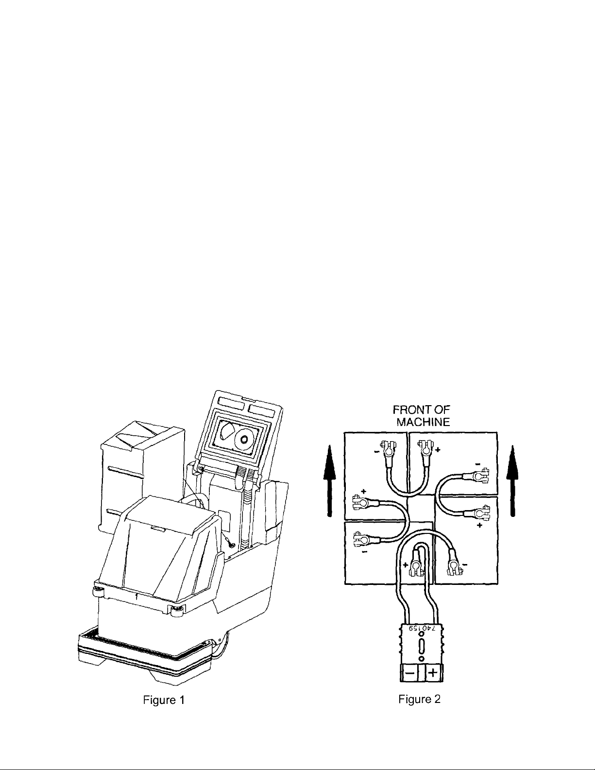
1. Disconnect tank drain hose from rear of machine (6).
2. Raise tank assembly by raising rear cover and tilting tank, Figure 1.
3. Install batteries as shown in Figure 2.
CHARGING OF BACHARGING OF BA
CHARGING OF BA
CHARGING OF BACHARGING OF BA
TTERIES:TTERIES:
TTERIES:
TTERIES:TTERIES:
Charging of batteries generates explosive gases. DO NOT CHARGE BATTERIES WHEN OPEN
FLAMES OR SPARKS ARE PRESENT. DO NOT SMOKE. Make sure the charger is turned off
before disconnecting it from the batteries. Charge the batteries in a well-ventilated area. Fluid levels
should be checked before and after charging and maintained at the proper levels.
2
Page 5
CONTROLCONTROL
CONTROL
CONTROLCONTROL
P P
ANELANEL
P
ANEL
P P
ANELANEL
IDENTIFICA IDENTIFICA
IDENTIFICA
IDENTIFICA IDENTIFICA
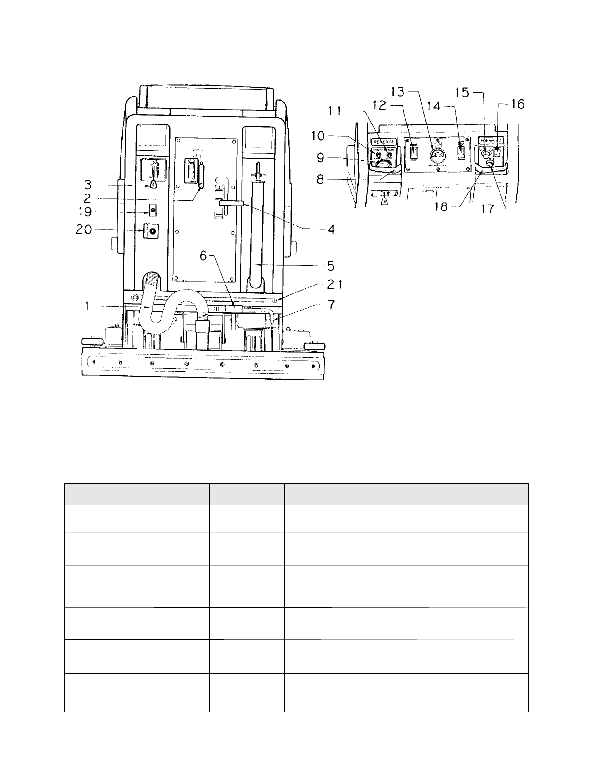
1. Vacuum recovery hose
2. Squeegee lift lever
3. Solution control lever
4. Brush pressure handle
5. Drain hose for recovery tank
6. Foot pedal for lower/raising brush
7. Drain hose for battery tray
8. Reverse control lever
9. Hour meter (optional)
10. Circuit breaker for vacuum motor
11. Circuit breaker for brush motor
12. Brush switch
13. Battery condition gauge
14. Vacuum switch
15. Speed control knob
16. Main power switch
17. Key switch (optional)
18. Forward control lever
19. Pump switch (optional)
20. Quick disconnect aux. out (optional)
21. Dump hose for solution tank
TIONTION
TION
TIONTION
AUTO SCRUBBER BRUSH DESCRIPTIONAUTO SCRUBBER BRUSH DESCRIPTION
AUTO SCRUBBER BRUSH DESCRIPTION
AUTO SCRUBBER BRUSH DESCRIPTIONAUTO SCRUBBER BRUSH DESCRIPTION
TYPE TYPE
TYPE
TYPE TYPE
Bassine Natural Fiber Short Dark Red Light duty
Nylon Nylon Medium Black Tan/Red General cleaning
Dyna-Scrub Nylon impregnated Long Light Red General scrubbing,
Power-Scrub Nylon impregnated Long Rust Red/Blue Moderate aggressive
Poly-Grit Nylon impregnated Long Green Brown/Black Aggressive stripping
Strata-Grit Nylon impregnated Long Dark Black Heavy duty
DESCRIPTION DESCRIPTION
DESCRIPTION
DESCRIPTION DESCRIPTION
with 500 Grit Blue vinyl tile, ceramic
Silicone Carbide tile, epoxy floors,
Fine Bristle, urethane finish,
Dense Fill uneven concrete floors
with 120 Grit Silicon scrubbing, tile floors
Carbide Fine Bristle, concrete floors
Dense Fill
with 80 Grit and scrubbing, tile
Silicon Carbide floors, unfinished
Coarse Bristle concrete floors
with 46 Grit Blue stripping/scrubbing
Silicon Carbide unfinshed
Coarse Bristle concrete
**
Durability is dependent on floor surface, chemicals used and proper care. Durability is dependent on floor surface, chemicals used and proper care.
*
Durability is dependent on floor surface, chemicals used and proper care.
Durability is dependent on floor surface, chemicals used and proper care. Durability is dependent on floor surface, chemicals used and proper care.
**
DURABILITY* DURABILITY*
DURABILITY*
DURABILITY* DURABILITY*
COLOR COLOR
COLOR
COLOR COLOR
Brown general cleaning,
COMP COMP
COMP
COMP COMP
TT
T
TT
ARISONARISON
ARISON
ARISONARISON
O PO P
ADSADS
O P
ADS
O PO P
ADSADS
RECOMMENDED RECOMMENDED
RECOMMENDED
RECOMMENDED RECOMMENDED
USE USE
USE
USE USE
acid etching
& scrubbing vinyl
floors, ceramic tile
& concrete floors
3
Page 6
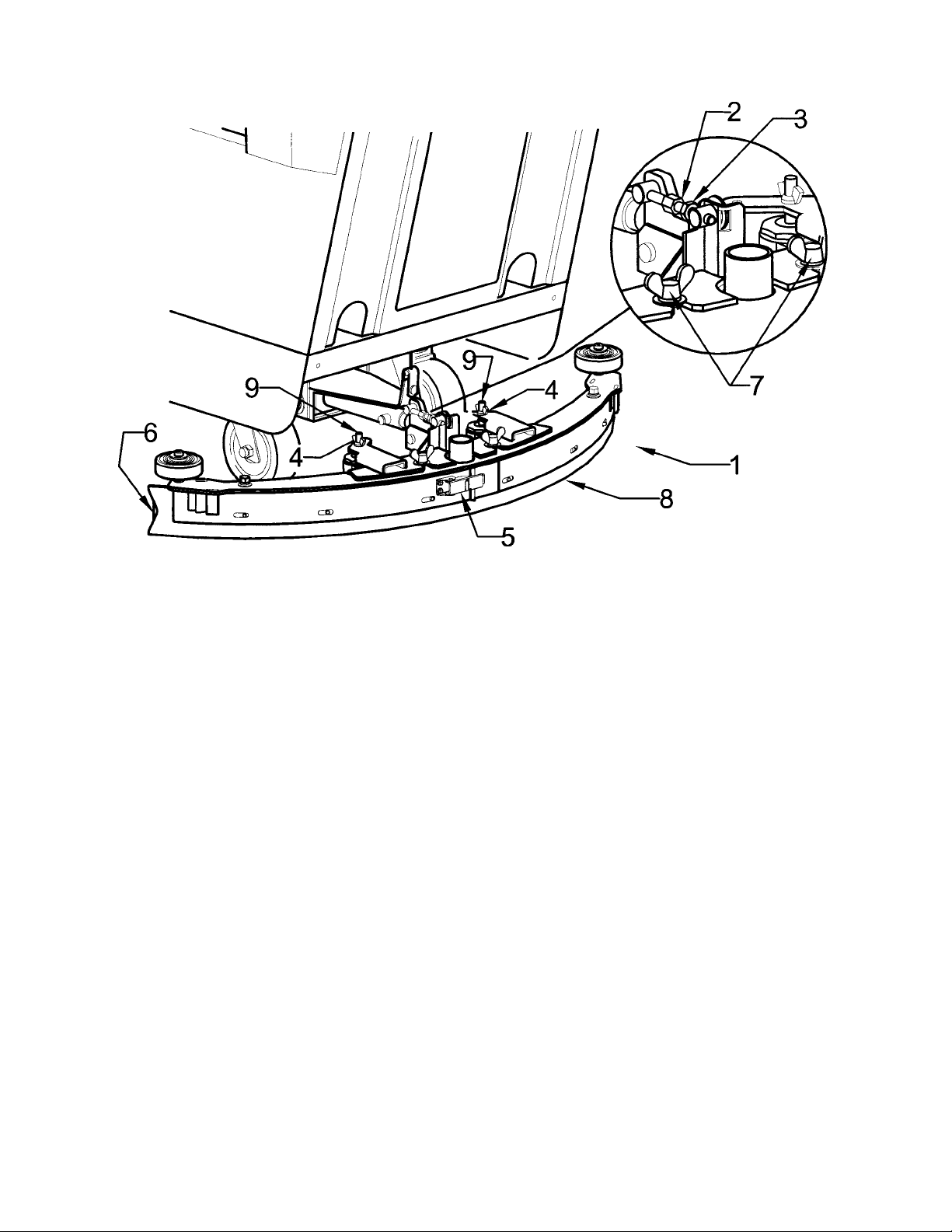
SQUEEGEE SQUEEGEE
SQUEEGEE
SQUEEGEE SQUEEGEE
ADJUSTMENTSADJUSTMENTS
ADJUSTMENTS
ADJUSTMENTSADJUSTMENTS
The squeegee set-up is pre-adjusted at the factory. Adjustments may be required to get optimum performance for
different floors and conditions.
Ensure that the scrubber is on a relatively flat surface. Ensure that the scrubber is on a relatively flat surface.
1.
Ensure that the scrubber is on a relatively flat surface.
Ensure that the scrubber is on a relatively flat surface. Ensure that the scrubber is on a relatively flat surface.
head assembly ofhead assembly of
head assembly of
head assembly ofhead assembly of
2. Turn the speed control knob counter-clockwise to the low speed position. Squeeze the forward control lever to lower
the squeegee (item 1) to the floor. Move the machine one or two feet forward to check the rear squeegee blade (item
8) for uniform deflection to the floor.
3. If uneven deflection or lay is evident, minor adjustments may be necessary to avoid streaking and uneven wear on
the blade.
4. To correct this, loosen the wing jam nut (item 4) in order to adjust the caster height. If the squeegee blade is
deflecting too much, the casters need to be lowered to control the down pressure. Lower the caster by turning the
exposed threaded stem (item 9) on the caster clockwise. Make the adjustment a few turns at a time.
5. Repeat step 2.
6. If the blades are not deflecting enough, raise the caster by turning the stem counter-clockwise to adjust the caster
hieght to allow more down pressure on the squeegee. Repeat Step 2.
7. Make sure that there is an even deflection on the entire length of the rear blade. Adjust the castors and retighten the
wing jam nuts to lockthe caster setting in place.
8. Pitch adjustment is necessary if the outer ends on the squeegee blade does not contact the floor and there is too
much deflection in the middle area or if the outer ends are over deflected and there is no contact in the middle.
9. To adjust pitch, lower the squeegee to the floor. Loosen the lock nut (item 3) in the turnbuckle assembly. Turning
the turnbuckle (item 2) clockwise or counterclockwise controls the forward and backward pitch of the squeegee.
Having the rear blades deflected uniformly along its entire length is the desired setup.
10. Repeat Step 2 until the desired setup is achieved.
11. In certain applications where a non-slotted front wiper blade (item 6) is needed, detach the squeegee assembly by
loosening the wing bolts (item7). Unlock the clamp on the front squeegee to release the straps and flip the blade
over to the non-slotted side. Reattach straps and lock the clamp back in place.
12. You can also easily replace the rear blade by unlatching the latch (item 5) and removing the straps by sliding them
off the assembly.
f the floorf the floor
f the floor
f the floorf the floor
. Set the squeegee/ vacuum switch to the automatic mode.. Set the squeegee/ vacuum switch to the automatic mode.
. Set the squeegee/ vacuum switch to the automatic mode.
. Set the squeegee/ vacuum switch to the automatic mode.. Set the squeegee/ vacuum switch to the automatic mode.
TT
urn on the main power switch and raise the scruburn on the main power switch and raise the scrub
T
urn on the main power switch and raise the scrub
TT
urn on the main power switch and raise the scruburn on the main power switch and raise the scrub
4
Page 7

OPERAOPERA
OPERA
OPERAOPERA
1. Filling: Fill the solution tank with the desired amount of water and add liquid cleaning solution to
the proper dilution ratio. DO NOT USE powdered cleaning chemicals. Powders are unlikely to
dissolve thoroughly, resulting in clogging the in-line solution filter. This can reduce or stop water
flow to the brush.
2. Close lid.
3. Turn on main power switch (refer to Page 3, #16). (Traction Drive Only)
4. Adjust main speed control, #15 to full counter-clockwise position. (Traction Drive Only)
5. Lower brush assembly:
• Depress foot pedal (6) slightly and push in on lever (4) to release, to increase brush pressure
pull up and back on lever (4) to lock in position.
• To lift the brush, press the pedal down until lift mechanism engages.
6. Turn on brush switch.
7. Adjust solution control feed lever.
8. Select vacuum operation:
Brush Driven Models – Turn vacuum switch to “On” position Traction Driven Models
a) “Vacuum On” mode – Vacuum will remain on until switched to the “off” position
b) “Vacuum Auto” mode – Vacuum will come on automatically when forward or reverse handles
are squeezed, and remain on approximately 5 seconds after handle release.
TING INSTRUCTIONSTING INSTRUCTIONS
TING INSTRUCTIONS
TING INSTRUCTIONSTING INSTRUCTIONS
9. Lower squeegee assembly.
10. Squeeze forward handle #18 and adjust forward speed. (Traction Drive Only)
After Use:
1. Turn off solution feed.
2. Switch off brush and raise.
3. Raise squeegee assembly.
4. Turn off vacuum motor.
5. Solution and recovery tanks should be emptied after every use.
MAINTENANCE:MAINTENANCE:
MAINTENANCE:
MAINTENANCE:MAINTENANCE:
Daily
1. Clean float assembly & squeegee blades.
2. Recharge batteries (check battery acid levels before and after charging).
Monthly
1. Check wear on squeegee blades.
2. Grease front and rear wheels.
3. Grease pivot points on brush motor assembly.
Every 500 hours check condition of carbon brushes on vacuum motor and brush drive motor.
5
Page 8
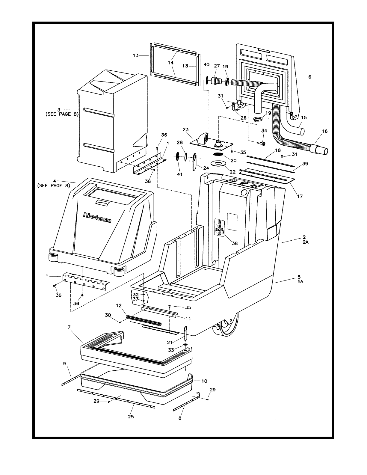
6
Page 9

PartPart
Part
PartPart
s Lists List
s List
s Lists List
ItemItem
Item
ItemItem
10 260145 1 Splash Skirt
11 260148 1 Solution Dump Bracket 14GA
12 260149 1 U Channel 12”
13 260157 2 Lid Gasket Short 260B
14 260158 2 Lid Gasket 260B
15 260159 1 Hose Vac 1.5 x 78” Wireloc
16 260160 1 Recovery Hose Assy. 260B
17 260169 1 Lid Flap
18 260170 2 Retainer Strip
19 260203 2 Clamp Hose 102120 Murray
20 260212 1 Screen Filter
21 260241 2 Pin Hitch 7/16 x 3
22 260294 1 Gasket 260
23 260299 1 Shut-Off Plate Assy.
24 260301 1 Deflector Flap
25 260336 1 Skirt Retainer - Front
26 260353 2 Lid Pivot Strap
27 450037 1 Adapter MCH
28 450081 1 WSR-1.908 x 2.41 x .03 SS
29 711106 20 SCR-ST-A 10 x .75 PL
30 711124 2 SCR-ST-B 10 x .37 NI
31 711161 10 SCR-Hi/Lo #10 x 3/4 Zinc
32 711505 4 WSR-Flat 1/4
33 711508 2 WSR-Flat .44 x 1.00 x .08
34 712102 2 Bolt - Shoulder 1/2 x 1.5
35 712540 14 SCR-MC 10-24 x .37 SS TH
36 712565 17 SCR-MC 1/4-20 x .62 SS
37 712667 4 Nut-Nyloc 1/4-20 SS
38 715607 1 Decal - Battery Cable Rout
39 760263 2 Foam Tape 1/16 x 1/2
40 828970 1 WSR-Neop 1.87 x 2.4 x .125
41 828971 1 Nut - 1 1/2 Pipe Thread
Part No.Part No.
Part No.
Part No.Part No.
1 260087 2 Hinge 15”
2 260090 1 Rear Base Char Grey
2A 260256 1 Rear Base 260TD Char Grey
3 260091 1 Recovery Tank 260 Light Grey
4 260092 1 Solution Tank 260 Light Grey
5 260093 1 Chassis MMN 260
5A 260360 1 Mainframe MMN 260TD
6 260096B 1 Lid Recovery 260 Burgundy
7 260098 1 Front Skirt 260 Black
8 260142 1 Skirt Retainer L.H.
9 260143 1 Skirt Retainer R.H.
QtyQty
Qty
QtyQty
..
DescriptionDescription
.
Description
..
DescriptionDescription
7
Page 10
Brush DrivenBrush Driven
Brush Driven
Brush DrivenBrush Driven
8
Page 11

PartPart
Part
PartPart
s Lists List
s List
s Lists List
ItemItem
Item
ItemItem
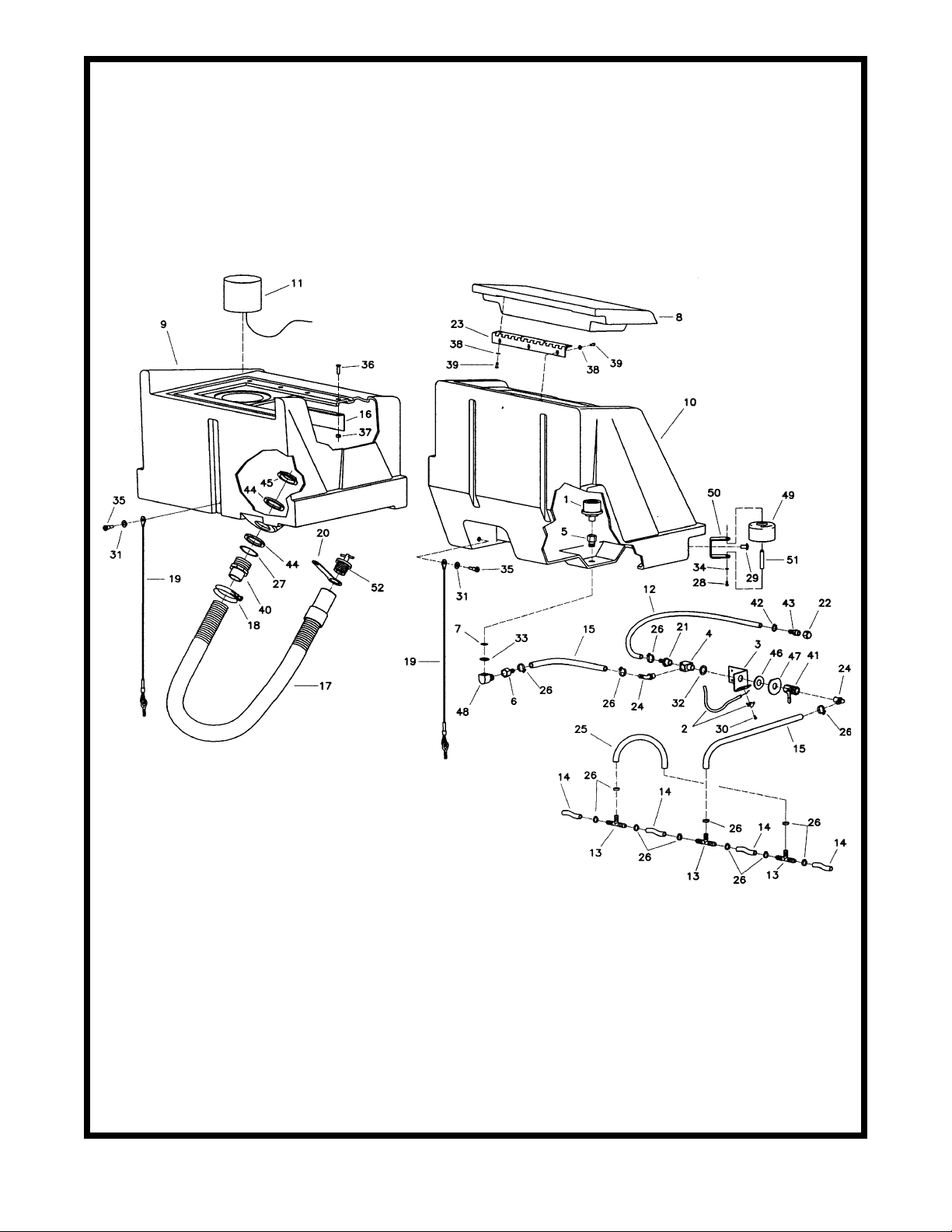
1 130118 1 Strainer Solution M3-40
2 210045 1 Cable Solution Control
3 210370 1 Solution Valve Bracket
4 210408 1 Fitting Brass Tee 3/8MPT x 3/8FPT
5 210409 1 Fitting Brass 3/8MPT x 3/8FPT
6 210410 1 Fitting Brass 3/8FPT x 3/8HOSE
7 210414 1 O-Ring 2-113
8 260029B 1 Solution Lid Burgundy
9 260091 1 Recovery Tank 260 Lt Grey
10 260092 1 Solution Tank 260 Lt Grey
11 260156 1 Float Assembly
12 260162 1 Hose, Solution Dump 38”
12A 260193 1 Solution Hose 3/8 Nylobr
13 260178 3 Fitting Nylon T 3/8 Hose
14 260179 4 Hose Nylobraid 3/8 x 2.38
15 260182 2 Solution Hose C/L 18"
16 260184 1 Support Angle
17 260202 1 Hose Assembly 260B New Style
18 260203 1 Hose Clamp 102120 Murray
19 260214 2 Tank Cable Assy. 260
20 320269 1 Strap, Drain Plug Retaining
21 342430 1 Fitting Brass 3/8MPT x 3/8HOSE
22 430114 1 Fitting Nylon Cap 1/4 FPT
23 450021 1 Hinge
24 450040 2 Elbow PLT 3/8MPT x 3/8BARB
25 450055 1 Hose Nylon 3/8 ID 9"
26 450076 13 Crimp Clamp SS 185R SS
27 450081 1 WSR 1.908 x 2.41 x .03 SS
28 710353 2 SCR-MC 10-32 x .37 Zinc
29 710985 2 SCR-SC 3/8-16 x .62
30 711124 1 SCR-ST-B 10 x .37 NI
31 711506 2 WSR-Flat 5/16 (Narrow) ST PL
32 711512 1 WSR-Flat .75 x 1.37 x .08
33 711513 1 WSR-Flat .689 x 1.06 x .029 SS
34 711553 2 WSR-Internal Lock #10
35 712041 2 Bolt-Shoulder 1/4-20 x .44 x .3
36 712563 4 SCR-MC 1/4-20 x 1.00 SS
37 712667 4 Nut-Hex Nyloc 1/4-20 SS
38 712764 7 WSR #10 SS
39 712822 7 SCR-MC TR HD 10-24 x .50 SS
40 760220MCH 1 1.5 Adapter MCH
41 809413MCH 1 Valve Solution
42 828490 1 Clamp Crimp 140R
43 828952 1 Fitting PP 1/4MPT x 3/8BARB
44 828970 2 WSR-Neop 1.87 x 2.4 x .125
45 828971 1 Nut 1 1/2 Pipe Thread
46 828975 1 WSR-Neop .75 x 1.5 x .09
47 829463 1 SS Washer
48 830062 1 Fitting Brass 90 3/8MPT x 3/8FPT
49 832896 2 Guide Wheel
50 832949 2 Bracket, Bumper
51 833254 2 Bumper Wheel Axle
52 833316 1 Drain Plug
Part No.Part No.
Part No.
Part No.Part No.
QtyQty
Qty
QtyQty
..
.
..
DescriptionDescription
Description
DescriptionDescription
9
Page 12

Brush DrivenBrush Driven
Brush Driven
Brush DrivenBrush Driven
10
Page 13

PartPart
Part
PartPart
s Lists List
s List
s Lists List
ItemItem
Item
ItemItem
1 210142 1 Pedal Pad
2 260030 5 Bushing .5015 x .628 x .375 OI
3 260041 2 Bushing-FLG .502 x .750 x .375
4 260043 1 Lift Arm, Left Side
5 260044 1 Lift Arm, Right Side
6 260046 1 Pedal Brace
7 260054 1 Pedal Weldment
8 260055PTD 1 Lift Handle Weldment
9 260075 1 Yoke Weldment
10 260090 1 Rear Base Char Gray
11 260093 1 Chassis MMN 260
12 260125 1 Bushing, Yoke .407 x 1.687 STL
13 260128 1 Spacer-Yoke
14 260130 2 Wheel 10" w/Bushing
15 260136 2 Wheel Axle Bracket Asy
16 260141 1 Spacer - Lift Arm
17 260317 1 Squeegee Mechanical Assy
18 710196 4 SCR-MC 5/16-18 x .62
19 710986 2 SCR BHCS 3/8-16 x 1.00 Zinc
20 710992 1 Shoulder Bolt 1/2 x 1.25 x 3/8
21 711228 8 Bolt HH 5/16-18 x .75 STL Zinc
22 711232 4 Bolt HH 5/16-18 x 1.50
23 711242 8 Bolt HH 3/8-16 x 1.00
24 711250 2 Bolt HH 3/8-16 x 1.25 STL Zinc
25 711374 2 Nut-Nyloc 5/16-18
26 711375 2 Nut-Nyloc 3/8-16 1/2 Nut
27 711380 2 Nut, Nyloc 3/8-16
28 711439 3 Nut Flanged Wizz 3/8-16
29 711507 2 WSR-Flat .37 x 1.12 x .06
30 711512 8 Washer Flat .75 x 1.38 x .08
31 711515 8 WSR-Flat .406 x .812 x .0625
32 711545 16 Washer Helical 5/16
33 711546 12 Washer Helical 3/8
34 711575 22 Washer Flat .31 x .75 x .06 STL
35 711579 2 WSR-Flat .56 x 1.00
36 712081 2 Shoulder Bolt 5/16-18 x .75
37 712099PLT 2 Shoulder Bolt 1/2 x 1/2
38 712310 6 WSR-Flat .52 x .87 x .06 PL
39 712680 4 Nut-Hex 5/16 -18 SS
40 713045 1 Bolt HH 3/8-16 x 1.75 #5
41 713048 1 Bolt HH 3/8-16 x 2.50 #5
42 762107 2 Spacer 1.00 x 1.25 x .25
43 762340 2 Bushing .502 x .625 x .270 STL
44 809247 2 Spacer .442 x .50 x .312
45 827110 2 Caster 5"
46 832829 2 Nut-U Type 5/16-18
Part No.Part No.
Part No.
Part No.Part No.
QtyQty
Qty
QtyQty
..
DescriptionDescription
.
Description
..
DescriptionDescription
11
Page 14

Brush DrivenBrush Driven
Brush DrivenBrush Driven
Brush Driven
12
Page 15

PartPart
Part
PartPart
ItemItem
Item
ItemItem
Part No.Part No.
Part No.
Part No.Part No.
1 210066 2 Drive Hub Retainer Bolt
2A 260002 2 Pad Holder-26B
2B 260003 2 Brush Feed Thru Bassine
2C 260004 2 Brush 26B Nylon
2D 260005 2 Brush Poly-Grit 26B
2E 260006 2 Brush Strata-Grit 26B
3 260009 1 Battery Tray
4 260030 8 Bushing .5015 x .628 x .375 OI
5 260036 12 Pin, Retainer
6 260038PTD 1 Motor Mount Weldment R.H.
7 260039PTD 1 Motor Mount Weldment L.H.
8 260041 13 Bushing-FLG .502 x .750 x .375
9 260042 1 Actuator Bar Weldment
10 260049 4 Linkage Bar
11 260053 2 Cable Push/Pull
12 260066 2 Bushing-FLG .377 x .687 x .406
13 260068 1 Spacer, Spring
14 260076 1 Bracket Anderson Plug
15 260077 1 Motor Frame Weldment
16 260114 2 Linkage Weldment
17 260123 1 Cable Bracket Weldment L.H.
18 260124 1 Cable Bracket Weldment R.H.
19 260137 1 Spring Comp .960 x 2.00 Zinc
20 260150 1 Battery Liner
21 260159 1 Hose Vac 1.5 x 78” Wireloc
22 260175 1 Cable Conduit
23 260183 1 Nut 1/4 NPT NYL
24 260193 1 Solution Hose 3/8 Nylobr
25 260194 1 Pressure Hose 3/8 x 50
26 260203 1 Clamp Hose 102120 Murray
27 260214 2 Tank Cable Assembly 260
28 260224 1 Drain Hose 1/4 x 18 Silicone
29 260315 1 Lift Cable Bracket
30 260377 1 Squeegee Cable
31 290017 1 Molded Vac Motor Gasket
32 320248 2 Clevis, Slotted
33 320271 1 Fitting PP 90 3/8MPT 3/8HOSE
34 320272 2 Nozzle Body Lock Nut
35 320273 1 Hose Shut-Off Clamp
36 364-816 1 Nut-Nyloc 1/2-13 Half
37 380064 1 Foam Ring
38 430035 2 Drive Hub
39 450038-H 2 Z-Bracket 5.7 VDE Zinc
40 450076 4 Crimp Clamp 185R SS
41 710180 2 SCR-MC 1/4-20 x .75 Zinc
42 710823 2 SCR-SC 1/4-20 x .50 Nylon
QtyQty
Qty
QtyQty
..
DescriptionDescription
.
Description
..
DescriptionDescription
s Lists List
s List
s Lists List
ItemItem
Item
ItemItem
Part No.Part No.
Part No.
Part No.Part No.
43 710986 8 SC 3/8-16 x 1.00 Zinc
44 711128 1 SCR-ST-B Hi-Lo 8 x .62 Zinc
45 711160 3 SCR-HI/LO #10 x 5/8 Zinc
46 711161 2 SCR-HI/LO #10 x 3/4 Zinc
47 711203 6 Bolt-HH 1/4-20 x .62
48 711210 2 Bolt-HH 1/4-20 x 1.25 STL Zinc
49 711228 2 Bolt-HH 5/16-18 x .75 STL Zinc
50 711316 2 Nut-Hex 1/4-20 ST PL
51 711334 2 Nut-Hex 1/2-13 ST PL
52 711350 4 Nut-Hex Nyloc 10-32
53 711368 2 Wing Nut Nyloc 1/4-20 PL
54 711375 3 Nut-Nyloc 3/8-16 1/2 Nut
55 711425 9 Nut-Flanged Wizz 1/4-20
56 711505 11 WSR-Flat 1/4
57 711510 1 WSR-Flat .50 x 1.37 x .10
58 711517 2 WSR-Flat .77 x 1.37 x .03
59 711524 2 WSR-Wave .52 x .87 x .01
60 711535 6 WSR-Helical 1/4
61 711545 2 WSR-Helical 5/16
62 711713 14 Ret Ring-E Ext .50
63 711717 2 Ret Ring-E Ext .37
64 712129 2 SCR-TR 1/4-20 x 1.00 HWH
65 712301 2 WSR-Flat .37 x .87 x .06 (Wide)
66 712310 25 WSR-Flat .52 x .87 x .06 PL
67 712545 4 SCR-MC 10-32 x .87 SS
68 712667 1 Nut-Hex Nyloc 1/4-20 SS
69 740132 2 Insulator (Glastic)
70 740159 1 Circuit Brkr-175 Red Housing
71 740209 2 Gearmotor 24V 17B
72 740225 1 Vac Motor 6515 24V
73 762073 1 Bushing .259 x .375 x .265
74 762256PLT 2 Nut Adj LH Zinc PLT
75 809444 1 Clip Cord
76 828264 1 Washer Cup
77 828490 1 Crimp Clamp 140R
78 829067 2 Crimp Clamp 560R
79 832996 1 Terminal Block 2 Pole VDE
80 833191 1 Hose Rubber Flex 2 x 9
81 833265PLT 1 Threaded Spacer PLT Zinc
82 833299 1 Pump 100 PSI 24V DC
83 833325 4 Fitting Nylon 90 1/4MPT 3/8HOSE
84 833638 2 Brass Stud
85 833725 2 Clip-T
86 840011 1 Vac Motor Cover, Top
87 840012 1 Vac Motor Cover, Bottom
QtyQty
Qty
QtyQty
..
DescriptionDescription
.
Description
..
DescriptionDescription
13
Page 16

Brush DrivenBrush Driven
Brush Driven
Brush DrivenBrush Driven
14
Page 17

DescriptionDescription
DescriptionDescription
Description
..
..
.
QtyQty
QtyQty
Qty
Part No.Part No.
Part No.Part No.
Part No.
ItemItem
ItemItem
Item
s Lists List
s Lists List
s List
PartPart
PartPart
Part
36 711595 1 WSR-Flat .59 x 1.18 x .09
37 711668 2 Clevis Pin 3/8 x 1 11-141
38 711671 1 Clevis Pin .31 x 2.13 11-10
39 711808 1 Pin-Hairpin Cotter #13
40 712070 1 Bolt-Shoulder 5/16 x 3/4 x 1/4
41 712100 2 Bolt-Shoulder 3/8 x 2.25
42 712310 1 WSR-Flat .52 x .87 x .06 PL
43 712320 8 WSR-Nylon .22 x .45 x .04 NYL
44 712540 6 SCR-MC 10-24 x .37 SS TH
45 712822 8 SCR-MC TR HD 10-24 x .50 SS
46 715144 1 Decal Aux. Pump (175)
47 715601 1 Decal Forward 260
48 715602 1 Decal Reverse 260
49 715603 1 Decal Squeegee Lift 260
50 715604 1 Decal Solution 260
51 715605 1 Decal Brush Position
52 740131 1 Circuit Breaker 70 amp Push Button
53 740132 2 Insulator (Glastic)
54 740188 1 Switch-20 amp 1.5HP
55 740216 1 Gauge Battery Condition
56 740241 1 Contactor 24V 50 amp
57 740247 1 Circuit Breaker 30 amp Push Button
58 760277 1 Switch Guard
59 760286 1 Wire Formed Hook
60 762400 1 Bushing Heyco 1-5/8 x 2-1/8
61 788147 1 Solenoid 24VDC
62 809311 2 Cotter Pin 7/64 x 1
63 809754 2 Switch Rocker
63CE 740711CE 2 Switch Dreefs w/Splashguard
64 828368 1 BH2-61 Male Coupler
65 831306 1 Fitting Brass 90 1/4MPT 1/4MPT
66 833102 1 Spring Knob .60 x .73 x 1.75 Z
67 833374 2 Pin-Hairpin Cotter 3/8
68 833473 1 Fitting Brass 1/4FPT x 3/8HOSE
69 833638 2 Brass Stud
70 881002 2 Clevis Pin 11-083 Zinc
DescriptionDescription
DescriptionDescription
Description
..
..
.
QtyQty
QtyQty
Qty
Part No.Part No.
Part No.Part No.
Part No.
1 210045 1 Cable Solution Control
2 260053 2 Cable Push/Pull
3 260066 4 Bushing-FLG .377 x .687 x .406
4 260069MCH 1 Left Handle Machined
5 260070MCH 1 Right Handle Machined
ItemItem
ItemItem
Item
6 260081 1 Cable Mount Weldment
7 260084BDSP 1 Dashboard, 260BD Screen Printed
7CE 260084BCEDSP 1 Dashboard, 260BD CE Screen Printed
8 260099 1 Control Lever Mounting Bracket
9 260173 1 Electrical Box MTG
11 260274 2 Grommet Z-421
10 260194 1 Pressure Hose 3/8 x 50”
12 260284 1 Rear Panel Asy 260TD
13 260286 1 Squeegee Handle Weldment
14 260291 1 Handle Grip 260TD
15 260325 1 Handle Bracket
16 260337 1 Squeegee Cable
17 320248 2 Clevis, Slotted
18 320297 1 320 Squeegee Assembly New
15
19 430051 2 Spring-Return .313 x .438 x 2.
20 450059 1 Fitting Brass 1/4MPT 1/4MPT
21 450076 1 Crimp Clamp 185R SS
22 710178 4 SCR-MC TR HD 1/4-20 x .50 Zinc
23 710180 17 SCR-MC 1/4-20 x .75 Zinc
24 711125 2 SCR-ST-B 10 x .50 NI
25 711128 2 SCR- ST-B HI/LO 8 x .62 Zinc
26 711161 2 SCR-HI/LO #10 x 3/4 Zinc
27 711368 2 Wing Nut Nylon 1/4-20 PL
28 711373 1 Nut-Nyloc 1/4-20
29 711420 2 Nut-Hex Jam 5/16-18 STPL
30 711503 2 WSR-Flat #10
31 711505 4 WSR-Flat 1/4
32 711523 4 WSR-WAVE .37 x .68 x .08
33 711544 4 WSR-Helical 1/4
34 711575 1 WSR-Flat .31 x .75 x .06 STL
35 711594 1 WSR-Flat .56 x .88 x .03 Nickel
Page 18

raction Drivenraction Driven
raction Drivenraction Driven
raction Driven
TT
TT
T
16
Page 19

PartPart
Part
PartPart
s Lists List
s List
s Lists List
ItemItem
Item
ItemItem
1 130118 1 Solution Strainer M3-40
2 210045 1 Cable Solution Control
3 210370 1 Solution Valve Bracket
4 210408 1 Fitting Brass Tee 3/8 MPT 3/8 FPT
5 210409 1 Fitting Brass 3/8 MPT 3/8 FPT
6 210410 1 Fitting Brass 3/8 FPT 3/8 Hose
7 210414 1 O-Ring 2-113
8 260029B 1 Solution Lid Burgundy
9 260091 1 Recovery Tank 260 Lt Gray
10 260092 1 Solution Tank 260 Lt Gray
11 260156 1 Float Assembly
12 260162 1 Hose - Solution Dump 38"
13 260178 3 Fitting Nylon T 3/8 Hose
14 260179 4 Hose Nylobraid 3/8 x 2.38"
15 260182 1 Solution Hose C/L 18”
16 260184 1 Support Angle
17 260202 1 Hose Assembly 260B New Style
18 260203 1 Hose Clamp 102120 Murray
19 260214 2 Tank Cable Assembly
20 260215 1 Bracket Water Valve
21 260216 1 Solution Reinforced 3/8 x 14.75
22 320254 1 Solution Reinforced
23 320269 1 Strap, Drain Plug Retaining
24 342430 1 Fitting Brass 3/8 MPT x 3/8 HOSE
25 430114 1 Fitting Nylon Cap 1/4 FPT
26 450021 1 Hinge
27 450040 2 Elbow PLT 3/8 MPT 3/8 Barb
28 450055 1 Hose Nylon 3/8 ID x 9"
29 450076 15 Crimp Clamp 185R SS
30 450081 1 WSR-SS 1.908 x 2.41 x .03 SS
31 710353 2 SCR-MC 10-32 x .37 Zinc
32 710985 2 SC 3/8-16 x .62
33 711124 1 SCR-ST-B 10 x .37 NI
34 711506 2 WSR-Flat 5/16 (Narrow) ST PL
35 711512 1 WSR-Flat .75 x 1.37 x .08
36 711513 1 WSR-Flat .689 x 1.06 x .029 SS
37 711553 2 WSR-Internal Lock 10
38 712041 2 Bolt-Shoulder 1/4-20 x .44 x .3
39 712540 7 SCR-MC 10-24 x .50 SS TH
40 712560 4 SCR-MC 1/4-20 x .50 SS NYL
41 712563 4 SCR-MC 1/4-20 x 1.00 SS
42 712667 4 Nut-Hex Nyloc 1/4-20 SS
43 712764 7 WSR-Flat #10 SS
44 740482 1 Diode Assembly
45 740493 1 Water Valve 24VDC
46 760220MCH 1 1.5 Adapter MCH
47 809413MCH 1 Valve, Solution
48 828490 2 Clamp-Crimp 140R
49 828952 1 Fitting PP 1/4MPT 3/8Barb
50 828970 2 WSR-Neop 1.87 x 2.4 x .125
51 828971 1 Nut 1 1/2 Pipe Thread
52 828975 1 WSR-Neoprene .75 x 1.5 x .09
53 829463 1 SS Washer
54 830062 1 Fitting Brass 90 3/8 MPT 3/8 FPT
55 832896 2 Guide Wheel
56 832949 2 Bracket, Bumper
57 833254 2 Bumper Wheel Axle
58 833316 1 Drain Plug
59 833325 1 Fitting Nylon 90 1/4MPT x 3/8Barb
Part No.Part No.
Part No.
Part No.Part No.
QtyQty
Qty
QtyQty
..
.
..
DescriptionDescription
Description
DescriptionDescription
17
Page 20

TT
raction Drivenraction Driven
T
raction Driven
TT
raction Drivenraction Driven
18
Page 21

PartPart
Part
PartPart
s Lists List
s List
s Lists List
ItemItem
Item
ItemItem
1 210142 1 Pedal Pad
2 260030 5 Bushing-.5015 x .628 x .375 OI
3 260041 2 Bushing-FLG .502 x .750 x .375
4 260043 1 Lift Arm, Left Side
5 260046 1 Pedal Brace
6 260044 1 Lift Arm, Right Side
7 260054 1 Pedal Weldment
8 260055PTD 1 Lift Handle Weldment
9 260075 1 Yoke Weldment
10 260125 1 Bushing, Yoke .407 x 1.687 STL
11 260128 1 Spacer-Yoke
12 260141 1 Spacer-Lift Arm
13 260256 1 Base 260TD Char Grey
14 260317 1 Squeegee Mech. Assy.
15 260360 1 Mainframe MMN 260TD
16 260366 2 Transaxle Bracket 260TD
17 260370 2 Wheel 10 x 2.75 x .75 BORE
18 260371 2 Key 3/16 x 3/16 x 2.00
19 710196 4 SCR-MC 5/16-18 x .75
20 710986 2 SCR 3/8-16 x 1.00 Zinc
21 710992 1 Shoulder Bolt 1/2 x 1.25 x 3/8
22 711228 8 Bolt-HH 5/16-18 x .75 STL Zinc
23 711232 4 Bolt-HH 5/16-18 x 1.50
24 711250 2 Bolt-HH 3/8-16 x 1.25 STL Zinc
25 711374 2 Nut Nyloc 5/16-18
26 711375 2 Nut-Nyloc 3/8-16 1/2NUT
27 711380 2 Nut, Nyloc 3/8-16
28 711439 3 Nut-Flanged Wizz 3/8-16
29 711507 2 WSR-Flat .37 x 1.12 x .06
30 711512 2 WSR-Flat .75 x 1.37 x .08
31 711545 16 Washer Helical 5/16
32 711546 10 Washer Helical 3/8
33 711575 22 Washer Flat .31 x .75 x .06 STL
34 711579 2 WSR-Flat .56 x 1.00
35 712081 2 Shoulder Bolt 5/16-18 x .75
36 712099PLT 2 Shoulder Bolt 1/2 x 1/2
37 712310 6 WSR-Flat .52 x .87 x .06 PL
38 712680 4 Nut-Hex 5/16-18 SS
39 713042 4 Bolt-HH 3/8-16 x 1.00 #5
40 713045 1 Bolt-HH 3/8-16 x 1.75 #5
41 713048 1 Bolt-HH 3/8-16 x 2.50 #5
42 744160 1 Transaxle 13” 24V
43 762340 2 Bushing .502 x .625 x .270 STL
44 809226 2 WSR-Flat .40 x 1.50 x .12
45 809247 2 Spacer .442 x .50 x .312
46 827110 2 Caster 5”
47 832829 2 Nut-U Type 5/16 x 18
Part No.Part No.
Part No.
Part No.Part No.
QtyQty
Qty
QtyQty
..
.
..
DescriptionDescription
Description
DescriptionDescription
19
Page 22

raction Drivenraction Driven
raction Drivenraction Driven
raction Driven
TT
TT
T
20
Page 23

PartPart
Part
PartPart
s Lists List
s List
s Lists List
ItemItem
Item
ItemItem
Part No.Part No.
Part No.
Part No.Part No.
1 210066 2 Drive Hub Retainer Bolt
2A 260002 2 Pad Driver 26B
2B 260003 2 Brush Feed Thru Bassine
2C 260004 2 Brush 26B Nylon
2D 260005 2 Brush Polygrit 26B
2E 260006 2 Brush Stratagrit 26B
3 260009 1 Battery Tray 14GA
4 260030 8 Bushing .5015 x .628 x .375 OI
5 260036 13 Pin, Retainer
6 260038PTD 1 Motor Mount Weldment R.H.
7 260039PTD 1 Motor Mount Weldment L.H.
8 260041 13 Bushing-FLG .502 x .750 x .375
9 260049 4 Linkage Bar .312 GA
10 260066 2 Bushing-FLG .377 x .687 x .406
11 260068 1 Spacer, Spring
12 260076 1 Bracket Anderson Plug
13 260077 1 Motor Frame Weldment
14 260137 1 Spring Comp .960 x 2.00 Zinc
15 260150 1 Battery Liner
16 260159 1 Vac Hose 1.5 x 78” Wireloc
17 260175 1 Cable Conduit
18 260183 2 Nut 1/4 NPT Nyl
19 260187 1 Retainer Bar Weldment R.H.
20 260193 1 Solution Hose 3/8 Nylobr
21 260194 1 Pressure Hose 3/8 x 50”
22 260203 1 Clamp Hose 102120 Murray
23 260214 2 Tank Cable Assy. 260
24 260224 1 Drain Hose 1/4 x 18” Silicone
25 260250 1 Retainer Bar Weldment L.H.
26 260337 1 Squeegee Cable
27 260315 1 Lift Cable Bracket 3/16 GA
28 290017 1 Molded Vac Motor Gasket
29 320248 2 Pin-Clevis, Slotted
30 320271 1 Fitting PP 90 3/8MPT 3/8HOSE
31 320272 2 Nozzle Body Lock Nut
32 320273 1 Hose Shut-Off Clamp
33 380064 1 Foam Ring
34 430035 2 Drive Hub
35 450038-H 2 Z-Bracket 5.7 VDE Zinc
36 450076 4 Crimp Clamp 185R SS
37 710180 2 SCR-MC 1/4-20 x .75 Zinc
38 710129 2 SCR-MC 8-32 x .50 Zinc
QtyQty
Qty
QtyQty
..
.
..
DescriptionDescription
Description
DescriptionDescription
ItemItem
Item
ItemItem
Part No.Part No.
Part No.
Part No.Part No.
39 710823 2 SC 1/4-20 x .50 Nylon
40 710986 8 SC 3/8-16 x 1.00 Zinc
41 711128 1 SCR-ST-B Hi/Lo 8 x .62 Zinc
42 711160 3 SCR Hi/Lo 10 x 5/8 Zinc
43 711203 2 Bolt-HH 1/4-20 x .62
44 711210 2 Bolt-HH 1/4-20 x 1.25 STL Zinc
45 711228 2 Bolt-HH 5/16-18 x .75 STL Zinc
46 711334 2 Nut-Hex 1/2-13 ST PL
47 711350 4 Nut Nyloc 10-32
48 711368 2 Wing Nut Nyloc 1/4-20 PL
49 364-816 1 Nut-Nyloc 1/2-13 Half
50 711425 10 Nut-Flanged Wizz 1/4-20
51 711505 7 WSR-Flat 1/4
52 711510 2 WSR-Flat .50 x 1.37 x .10
53 711517 2 WSR-Flat .77 x 1.37 x .03
54 711544 2 WSR-Helical 1/4
55 711545 2 WSR-Helical 5/16
56 711713 13 Ret Ring-E Ext .50
57 711808 2 Pin-Hairpin Cotter #13
58 712301 6 WSR-Flat .37 x .87 x .06 (Wide)
59 712310 25 WSR-Flat .52 x .87 x .06 PL
60 712545 4 SCR-MC 10-32 x .87 SS
61 712667 1 Nut-Hex Nyloc 1/4-20 SS
62 740132 2 Insulator (Glastic)
63 740159 1 Circuit Brkr-175 Red Housing O
64 740209 2 Gearmotor 24V 17B
65 740225 1 Vac Motor 6515-13 24V
66 762073 1 Bushing .259 x .375 x .265
67 809444 1 Clip Cord
68 828264 1 Washer Cup
69 828490 1 Clamp-Crimp 140R
70 829067 2 Clamp-Crimp 560R
71 832996 1 Terminal Block 2POLE VDE
72 833191 1 Hose Rubber Flex 2 x 9
73 833265PLT 1 Threaded Spacer PLT Zinc
74 833299 1 Pump 100 PSI 24V DC
75 833325 4 Fitting Nylon 90 1/4MPT 3/8HOS
76 833621 2 Key 1/4 x 1/4 x 1
77 833638 2 Brass Stud
78 840011 1 Vac Motor Cover, Top
79 840012 1 Vac Motor Cover, Bottom
QtyQty
Qty
QtyQty
..
.
..
DescriptionDescription
Description
DescriptionDescription
21
Page 24

TT
raction Drivenraction Driven
T
raction Driven
TT
raction Drivenraction Driven
22
Page 25

45 712070 1 Bolt-Shoulder 5/16 x 3/4 x 1/4
46 712100 2 Bolt-Shoulder 3/8 x 2.25
47 712310 5 WSR-Flat .52 x .87 x .06 PL
48 712320 2 WSR-Nylon .22 x .45 x .04
49 712540 6 SCR-MC 10-24 x .37 SS TH
50 712570 2 SCR-MC 1/4-20 x 1.75 SS
s Lists List
s Lists List
s List
PartPart
PartPart
Part
DescriptionDescription
DescriptionDescription
Description
..
..
.
QtyQty
QtyQty
Qty
52 712822 8 SCR-MC 10-24 x .87 Zinc
51 712814 1 SCR-MC TR HD 10-24 x .50 SS
53 715144 1 Decal Aux. Pump (175)
54 715602 1 Decal Reverse 260
55 715603 1 Decal Squeegee Lift 260
56 715604 1 Decal Solution 260
57 715605 1 Decal Brush Position
58 715608 1 Decal Forward 260TD
59 740131 1 Circuit Breaker 70 amp Push Button
60 740132 2 Insulator (Glastic)
61 740188 1 Switch 20amp 1.5hp
62 740216 1 Gauge Battery Condition
63 740241 2 Contactor 24V 50amp
64 740247 1 Circuit Breaker 30amp Push Button
65 740736 1 Switch - 3 Position
65CE 742102 1 Switch 23670C4D
66 740804 1 Potentiometer Assembly
67 740811 3 Switch Boot CE
68 740944-1 1 SPD Control 24V 1203A225
69 741005 1 Keyswitch On-Off
70 741007 1 Hour Meter 10-80 VDC
71 741037 1 Relay-True Off 24V 5sec
72 760277 1 Switch Guard
73 760286 1 Wire Formed Hook
74 762400 1 Heyco Bushing 1-5/8 x 2-1/8
75 788147 1 Solenoid 24VDC
76 805637 1 SCR Insulator
77 809311 2 Cotter Pin 7/64 x 1
78 809754 2 Switch Rocker
78CE 740711CE 2 Switch Dreefs w/Splashguard
79 809874 1 Knob Speed Control
80 827060 1 Switch-Drive
81 828368 1 BH2-61 Male Coupler
82 828935 2 Spacer
83 831306 1 Fitting Brass 90 1/4MPT 1/4FPT
84 832015 2 Spacer .38 x .5 x .14
85 833102 1 Spring Knob .60 x .73 x 1.75 Z
86 833374 2 Pin Hairpin Cotter 3/8
87 833473 1 Fitting Brass 1/4FPT x 3/8HOSE
88 833638 2 Brass Stud
89 881002 2 Clevis Pin 11-083 Zinc
Part No.Part No.
Part No.Part No.
Part No.
1 200340 2 Spacer-SCR Board
2 210045 1 Cable Solution Control
3 260066 4 Bushing-FLG .377 x .687 x .406
4 260069MCH 1 Left Handle Machined
5 260070MCH 1 Right Handle Machined
6 260099 1 Control Lever Mounting Bracket
ItemItem
ItemItem
Item
7 260084TDSP 1 Dashboard 260TD Screen Printed
7CE 260084CETDSP 1 Dashboard 260TDCE Screen Printed
8 260194 1 Pressure Hose 3/8 x 50
9 260198 1 Switch Bracket 260TD
11 260253 1 Electrical Panel
10 260210 1 Moisture Guard SCR 260TD
12 260254 1 Switch Actuator 260TD
13 260255 1 Speed Control Bracket 260TD
13CE 260255CE 1 Speed Control Bracket 260TDCE
14 260274 3 Grommet Z-421
15 260284 1 Rear Panel Asy 260TD
16 260286 1 Squeegee Handle Weldment
17 260291 1 Handle Grip 260TD
18 260337 1 Squeegee Cable
23
19 320248 2 Clevis, Slotted
20 320297 1 320 Squeegee Assembly New
21 430051 2 Return Spring .313 x .438 x 2.
22 450059 1 Fitting Brass 1/4MPT 1/4MPT
23 450076 1 Crimp Clamp 185R SS
24 710178 4 SCR-MC TR HD 1/4-20 x .50 Zinc
25 710180 15 SCR-MC 1/4-20 x .75 Zinc
26 711125 2 SCR-ST-B 10 x .50 NI
27 711128 2 SCR-ST-B HI/LO 8 x .62 Zinc
28 711161 6 SCR-HI/LO 10 x 3/4 Zinc
29 711368 2 Wing Nut Nyloc 1/4-20 PL
30 711372 2 Nut-Nyloc 8-32
31 711373 1 Nut-Nyloc 1/4-20
32 711420 2 Nut-Hex Jam 5/16-18 STPL
33 711503 2 WSR-Flat #10
34 711505 4 WSR-Flat 1/4
35 711506 2 WSR-Flat 5/16 (Narrow) STPL
36 711523 4 WSR-WAVE .37 x .68 x .08
37 711544 4 WSR-Helical 1/4
38 711553 1 WSR-Internal Lock #10
39 711575 1 WSR-Flat .31 x .75 x .06 STL
40 711594 1 WSR-Flat .56 x .88 x .03 Nickel
41 711595 1 WSR-Flat .594 x 1.18 x .09
42 711668 2 Clevis Pin 3/8 x 1 11-141
43 711671 1 Clevis Pin .31 x 2.13 11-10
44 711808 1 Pin-Hairpin Cotter #13
Page 26

Squeegee Mechanism Squeegee Mechanism
Squeegee Mechanism
Squeegee Mechanism Squeegee Mechanism
260317260317
260317
260317260317
AssemblyAssembly
Assembly
AssemblyAssembly
PartPart
Part
PartPart
ItemItem
Item
ItemItem
1 210375 1 Swivel Pin
2 210391 2 Torsion Spring .563 x 2.595 SS
3 210400 2 Spacer Tube
4 260041 2 Bushing-FLG .502 x .750 x .375
5 260292 4 Swing Bolt Zinc Plated
6 260312 1 Yoke Weldment 260
7 260314 1 Spring Housing Weldment
8 320008 2 Pivot Bracket Asy
9 430051 2 Return Spring .313 x .438 x 2.0
10 712592 2 SCR-MC TH 1/4-20 x 3.00 SS
11 711425 2 Nut-Flange Wizz 1/4-20
12 711504 1 WSR-Flat 1/4 SS
13 711517 2 WSR-Flat .77 x 1.37 x .03
14 711671 1 Pin Clevis .31 x 2.12 11-10
15 711715 2 Ret Ring-E Ext .75
16 711808 1 Pin-Hairpin Cotter #13
17 712320 2 WSR-Nylon .22 x .45 x .04 NYL
18 712536 2 SCR-MC 10-24 x .62 SS
19 712562 1 Bolt-HH 1/4-20 x .75 SS
20 712665 2 Nut-Hex 1/4-20 SS
21 712758 1 WSR-Helical 1/4 SS
Part No.Part No.
Part No.
Part No.Part No.
s Lists List
s List
s Lists List
QtyQty
..
Qty
.
QtyQty
..
DescriptionDescription
Description
DescriptionDescription
24
Page 27

SQUEEGEE SQUEEGEE
SQUEEGEE
SQUEEGEE SQUEEGEE
320297320297
320297
320297320297
ASSEMBLASSEMBL
ASSEMBL
ASSEMBLASSEMBL
YY
COMPLETE COMPLETE
Y
COMPLETE
YY
COMPLETE COMPLETE
Parts ListParts List
Parts List
Parts ListParts List
25
Page 28

ANDARD MODELANDARD MODEL
ANDARD MODELANDARD MODEL
ANDARD MODEL
WIRING DIAGRAM BRUSH DRIVE STWIRING DIAGRAM BRUSH DRIVE ST
WIRING DIAGRAM BRUSH DRIVE STWIRING DIAGRAM BRUSH DRIVE ST
WIRING DIAGRAM BRUSH DRIVE ST
26
Page 29

WIRING DIAGRAM BRUSH DRIVE CE MODELWIRING DIAGRAM BRUSH DRIVE CE MODEL
WIRING DIAGRAM BRUSH DRIVE CE MODELWIRING DIAGRAM BRUSH DRIVE CE MODEL
WIRING DIAGRAM BRUSH DRIVE CE MODEL
27
Page 30

ANDARD MODELANDARD MODEL
ANDARD MODELANDARD MODEL
ANDARD MODEL
TRACTION DRIVE STTRACTION DRIVE ST
TRACTION DRIVE STTRACTION DRIVE ST
TRACTION DRIVE ST
WIRING DIAGRAM WIRING DIAGRAM
WIRING DIAGRAM WIRING DIAGRAM
WIRING DIAGRAM
28
Page 31

WIRING DIAGRAM TRACTION DRIVE CE MODELWIRING DIAGRAM TRACTION DRIVE CE MODEL
WIRING DIAGRAM TRACTION DRIVE CE MODELWIRING DIAGRAM TRACTION DRIVE CE MODEL
WIRING DIAGRAM TRACTION DRIVE CE MODEL
29
Page 32

LIMITED WLIMITED W
LIMITED W
LIMITED WLIMITED W
Minuteman International, Inc. warrants to the original purchaser/user that this product is free from defects in workmanship and
materials under normal use and service for a period of three years from date of purchase. In addition, Minuteman International,
Inc. will, at its option, honor labor warranty claims for the first 12 months from date of sale, provided such claims are submitted
through and approved by factory authorized repair stations. Minuteman International, Inc. will, at its option, repair or replace
without charge, except for transportation costs, parts that fail under normal use and service when operated and maintained in
accordance with the applicable operation and instruction manuals.
This warranty does not apply to normal wear, or to items whose life is dependent on their use and care, such as belts, cords,
switches, hoses, rubber parts, electrical motor components or adjustments. Parts not manufactured by Minuteman International,
Inc. such as engines, batteries, battery chargers, hydraulic pumps, and tires are covered by and subject to the warranties and/
or guarantees of their manufacturers. Please contact Minuteman International, Inc. for procedures in warranty claims against
these manufacturers.
SS
pecial warning to purchaserpecial warning to purchaser
S
pecial warning to purchaser — Use of replacement filters and/or prefilters not manufactured by Minuteman International, Inc.
SS
pecial warning to purchaserpecial warning to purchaser
or its designated licensees, will void all warranties expressed or implied.
A potential health hazard exists without exact original equipment replacement.
All warranteed items become the sole property of Minuteman International, Inc. or its original manufacturer, whichever the case
may be.
Minuteman International, Inc. disclaims any implied warranty, including the warranty of merchantability and the warranty of
fitness for a particular purpose. Minuteman International, Inc. assumes no responsibility for any special, incidental or consequential
damages.
ARRANTYARRANTY
ARRANTY
ARRANTYARRANTY
This limited warranty is applicable only in the U.S.A. and Canada, and is extended only to the original user/purchaser of this
product. Customers outside the U.S.A. and Canada should contact their local distributor for export warranty policies. Minuteman
International, Inc. is not responsible for costs or repairs performed by persons other than those specifically authorized by Minuteman
International, Inc. This warranty does not apply to damage from transportation, alterations by unauthorized persons, misuse or
abuse of the equipment, use of non-compatible chemicals, or damage to property, or loss of income due to malfunctions of the
product.
If a difficulty develops with this machine, you should contact the dealer from whom it was purchased.
This warranty gives you specific legal rights, and you may have other rights which vary from state to state. Some states do not
allow the exclusion or limitation of special, incidental or consequential damages, or limitations on how long an implied warranty
lasts, so the above exclusions and limitations may not apply to you.
A Minuteman International Company
World HeadquartersWorld Headquarters
World Headquarters Minuteman Canada, Inc.
World HeadquartersWorld Headquarters
Minuteman International, Inc. 2210 Drew Road
111 South Rohlwing Road Mississauga, Ontario
Addison, Illinois 60101 L5S 1B1
(630) 627-6900 (905) 673-3222
FAX (630) 627-1130 FAX (905) 673-5161
988010
Rev. A 9/05
Printed in U.S.A.
 Loading...