

Page 1

Instruction manual
Kleen Sweep 25W (625821)
Page 2

Introduction
Preface
Introduction
Dear customer,
We hope that the excellent qualities of
the machine justify the faith you have
shown in us by purchasing the product.
In order to ensure that you can work
with the machine safely, please read
the chapter on safety before running
the machine for the first time.
Your safety, and that of others, is dependent on your ability to control the
machine. Therefore, read the operating
manual thoroughly before operating the
machine for the first time.
The operating manual contains all the
important information you need to operate, maintain and service the machine.
Sections of this operating manual which
are relevant to safety are marked by the
hazard label.
If you have any questions with regard to
the machine or operating manual, you
can contact your service partner
at any time.
We would like to emphasize that no legal claims can be asserted in respect of
any work described in this manual.
Please pay attention that only original
spare parts are used for any necessary
maintenance and repair work. Only
original spare parts can guarantee long,
reliable equipment operation. We reserve the right to make technical improvements.
Valid from: January 2009
Minuteman International Inc.
14N845 U.S. Route 20
PINGREE GROVE, II. 60140-8893
U.S.A.
Intended use
The Kleen Sweep 25W is a sweeping
machine conceived exclusively for
sweeping up dry and wet surface
areas such as production plants, warehouses, parking lotsand pedestrian
walkways. In addition, the Kleen Sweep
25W can also be used to remove dry
dirt from carpets. Any use beyond this is
regarded as improper use. The manufacturer is not considered liable for any
damage resulting from improper use;
the user is solely responsible for all the
risks. Intended use also includes maintaining and observing the operating,
maintenance and repair conditions prescribed by the manufacturer.
The Kleen Sweep 25W may only be
operated, serviced and repaired by personnel who are familiar with the work involved and are aware of the risks. The
applicable accident prevention laws
must be observed and any generally
accepted health and safety directives
must be maintained. The manufacturer
is not deemed liable for any damage resulting from unauthorized modifications
to the machine.
2
Page 3

Introduction
Notes on warranty
The terms of the sales contract apply.
Damages are not subject to warranty if
they are due to non-compliance with the
maintenance and service provisions.
The maintenance work has to be performed by an authorized Minuteman service center and confirmed in the
"Maintenance certificate" which is the
warranty document.
The following is excluded from
warranty: fuses, natural wear, damages
caused by overload, inexpert handling
and unauthorized modification of the
machine. Moreover, any claim for warranty cannot be accepted if damages of
the machine are caused by fitting parts
or accessories without Minuteman's prior and explicit consent or by non-compliance with the maintenance
instructions.
Acceptance of the machine
Upon arrival, check machine for possible damages in transit. Follow unpacking instructions on shipping pallet.
Each unit has been tested and throughly inspected before shipment. Any damage is the responsibility of the delivery
carrier who should be notified immediately.
Minuteman International Inc.
14N845 U.S. Route 20
PINGREE GROVE, IL. 60140-8893
U.S.A.
3
Page 4

Table of content
Introduction . . . . . . . . . . . . . 2
Preface. . . . . . . . . . . . . . . . . . 2
Intended use . . . . . . . . . . . . . 2
Notes on warranty . . . . . . . . . 3
Acceptance of the machine . . 3
1 Safety Information . . . . . . . . 5
1.1 Safety and warning symbols . 5
1.2 General information . . . . . . . . 6
1.3 Operating information. . . . . . . 6
1.4 Maintenance information . . . . 6
1.5 Particular risks . . . . . . . . . . . . 7
1.6 Environmental protection . . . . 8
1.7 Labels on the machine. . . . . . 9
2 Starting Up . . . . . . . . . . . . . 11
2.1 Unpacking and assembling . 11
2.2 Instruction. . . . . . . . . . . . . . . 11
2.3 Initial battery charge. . . . . . . 11
2.4 Prior to starting up . . . . . . . . 12
2.5 Operation . . . . . . . . . . . . . . . 12
2.6 Stopping the machine . . . . . 12
2.7 After completing work. . . . . . 12
3 Operation . . . . . . . . . . . . . . 13
3.1 Method of operation . . . . . . . 13
3.2 Operating and indicator
elements. . . . . . . . . . . . . . . . 14
3.2.1 Operating panel . . . . . . . . . . 14
3.2.2 Operating elements on the ma-
chine. . . . . . . . . . . . . . . . . . . 16
4 Technical Data . . . . . . . . . . 18
5 Maintenance and
Service . . . . . . . . . . . . . . . . 20
5.1 System maintenance . . . . . 20
5.2 Proof of Maintenance . . . . . 21
5.3 Maintenance Plan . . . . . . . . 22
5.4 Battery system . . . . . . . . . . . 26
5.4.1 Charging batteries . . . . . . . . 27
5.4.2 Total discharge signal transduc-
er (TSG). . . . . . . . . . . . . . . . 27
5.4.3 Servicing the driving batteries .
27
5.4.4 Removing the batteries . . . . 27
5.4.5 Inserting the batteries. . . . . . 27
5.4.6 Disposing of batteries. . . . . . 27
5.5 Side brushes . . . . . . . . . . . . 28
5.5.1 Changing the side brush . . . 29
5.5.2 Setting the sweeping pattern 29
5.6 Rotary brush. . . . . . . . . . . . . 30
5.6.1 Cleaning the brush space . . 31
5.6.2 Changing the rotary brush . . 31
5.6.3 Setting the sweeping pattern 31
5.6.4 Changing the sealing strips . 31
5.6.5 Changing the timing belt . . . 31
5.7 Dust vacuum . . . . . . . . . . . . 32
5.7.1 Cleaning the filter. . . . . . . . . 33
5.7.2 Changing the filter . . . . . . . . 33
5.8 Sweepings container . . . . . . 34
5.8.1 Emptying the sweepings con-
tainer . . . . . . . . . . . . . . . . . . 35
5.8.2 Changing the seal . . . . . . . . 35
EC-Declaration of Conformity
37
4
Page 5
Safety Information
1 Safety Information
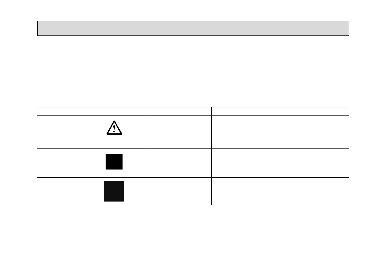
1.1 Safety and warning symbols
The following warning symbols appear
in the operating manual in those sections in which your safety, the safety of
the machine and environment could be
affected:
Symbol Damage to ... Definition
Safety information persons
or property
Note the machine Important information on handling the device to main-
Risk to environment the environment Risks to the environment through using substances
Safety symbol to indicate dangerous situations arising
through failure to follow instructions or prescribed work
procedures precisely or through ignoring them altogether.
tain its functioning ability.
which represent a risk to health and the environment.
5
Page 6

Safety Information
1.2 General information
• In addition to the information provided in this operating manual, all the
legally applicable health and safety
provisions must be observed.
• Before starting up the machine for
the first time, read the operating
manual supplied with it thoroughly as
well as any separate manuals provided with additional or attachment
devices and observe all the information during work.
• The equipment may only be operated, serviced and repaired by personnel trained by Minuteman technical
experts.
• Particular attention should be paid to
the information regarding safety.
Technical expertise is the key to preventing errors when operating the
machine and ensuring trouble-free
operation.
• The operating manual must always
be kept at the operating location of
the machine and, as a result, should
kept in a safe place on the equipment.
• If the equipment is sold or rented out,
these documents should be transferred to the new owner/operator.
The transfer should be confirmed!
• The warning labels attached to the
machine provided important information concerning safe operation. Illegible or missing labels must be
replaced by new ones.
• For reasons of safety, always use
original spare parts.
1.3 Operating information
• Before starting the machine up for
the first time, the battery to be used
must be fully charged, properly, by
implementing the initial battery
charge routine. Please pay attention
to the operating manual provided
with the charging unit as well as the
manual from the battery manufacturer. Minuteman assumes no liability for
damage to the battery caused by a
fault when the battery i s cha rged for
the first time.
• Check the operational safety of the
machine each time before starti ng i t
up! Clear any faults immediately!
• Before starting work, the operator
must be fully familiar with all adjustment, operating and control elements as well as their respective
function! It is too late to do this when
the machine is actually in operation!
• Always wear heavy duty, non-slip
footwear when working with the machine.
• The machine may only be used on
those surfaces which have been approved by the contractor or person
appointed by him.
• When using the machine, it is essential to pay attention to third partie s,
especially children.
• Accelerate the machine immediately
after switching on the brush head
drive, otherwise imprints of the brush
could be produced on the floor.
• The machine is not suitable for clearing up hazardous, flammable or
explosive fluids, dust or substances.
• It is forbidden to use the machine in
potentially explosive atmospheres.
• The side brush must be raised in order to transport the machine.
• The machine has been conceived for
use on level surfaces with a maximum gradient of 2%.
1.4 Maintenance information
• Operating personnel must complete
the necessary daily and weekly
maintenance work. All other mainte-
6
Page 7

Safety Information
nance work must be completed at
your local Minuteman service center.
• The maintenance work and maintenance intervals prescribed in the operating manual must be adhered to.
• Suitable tools must be used for
cleaning and maintenance work.
• The machine must be inspected by a
recognized technical expert in respect of operational safety, within
the terms of the applicable accident
prevention laws, at reasonable intervals (we recommend at least once a
year) and following modification or
repairs .
• Spare parts must comply with the
minimum technical requirements
stipulated by the manufacturer! This
is ensured by the use of original
spare parts.
• The machine must be switched off
prior to cleaning or servicing it or to
replacing parts. The drive bar must
be out of operation!
• Always disconnect the battery plug
before starting any work on the electrical installation.
• When working in the area of the
raised hood, it must be hinged open
fully to prevent it being knocked shut
or further open and down unintentionally.
• It is not permitted to clean the machine with a pressure washer or
steam blaster.
• It is not permitted to use aggressive
and corrosive cleaning agents.
• Allow the machine to dry after being
cleaned, e.g. over the weekend.
• Only start the machine up when all
the safety equipment has been installed and brought to its protecting
position.
1.5 Particular risks
Electronics
• In the case of defects in the electrical
installation, switch the machine off
immediately and clear the fault.
• Work on the electrical equipment
may only be carried out by electricians who have received the necessary training and in accordance with
the electrical engineering regulations.
• The machine's electrical equipment
must be inspected/checked at regular intervals. Defects, such as loose
connections and cable damage,
must be rectified immediately.
Batteries
• Observe the information in the operating manual provided by the battery
manufacturer.
• It is possible that sparking will occur
when connecting the batteries.
• Batteries may only be handled and
changed by properly skilled maintenance personnel.
• The machine has been set up for operation using maintenance-free batteries. If other battery types are
used, the machine must be set up for
use with them by an authorized
Minuteman service center.
• Never lay any metallic objects or
tools on batteries - risk of short circuit!
• For further safety information, refer
to supplementary sheet 88-60-2556
- notes on driving batteries.
7
Page 8

Safety Information
1.6 Environmental protection
• A certain factual expertise is required in order to use substances
which could represent a risk to
health and the environment.
• Observe the applicable laws and local regulations when disposing of
waste.
• Used batteries with the recycling
symbol contain reusable commodities. In accordance with symbol with
the crossed out bin, these batteries
must not be disposed of in domestic
waste. The return and recycling of
batteries must be agreed on with
Minuteman authorized dealers in accordance with § 8 BattV (Battery
Directive)!
8
Page 9
Safety Information
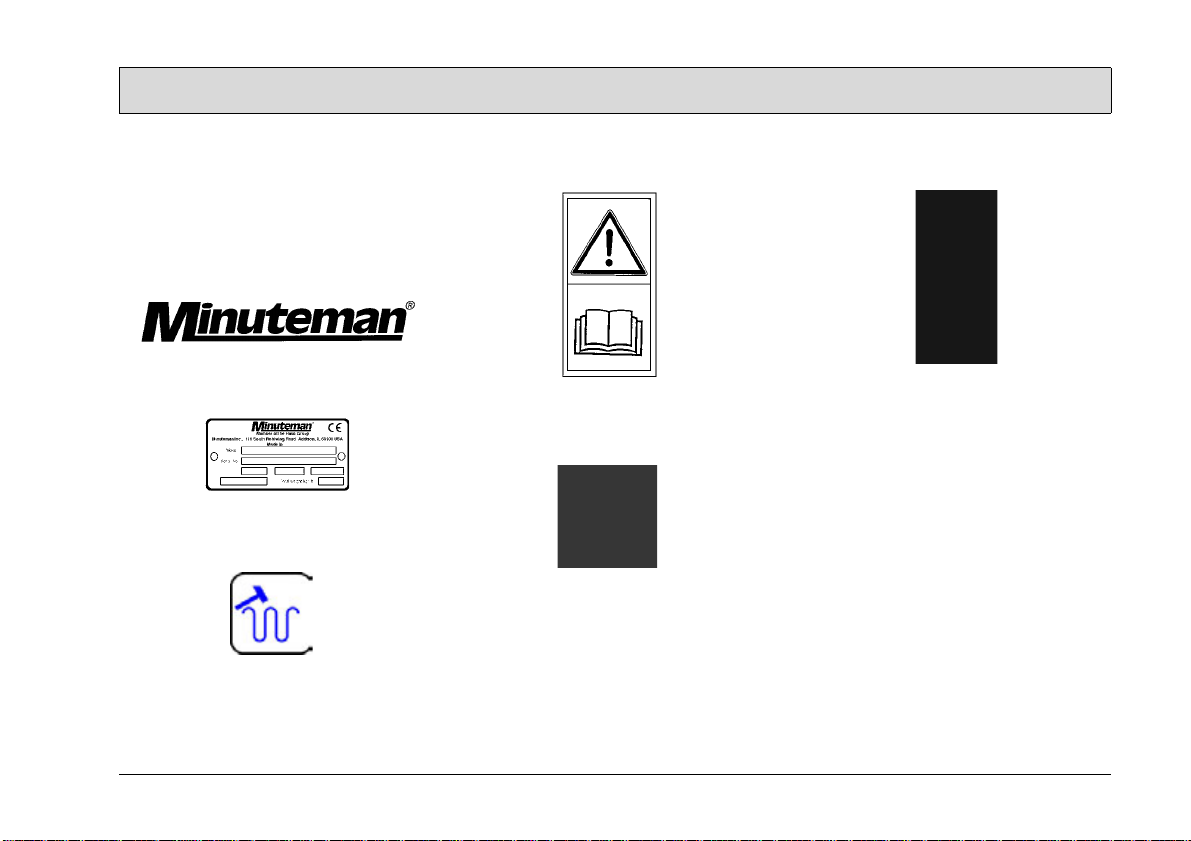
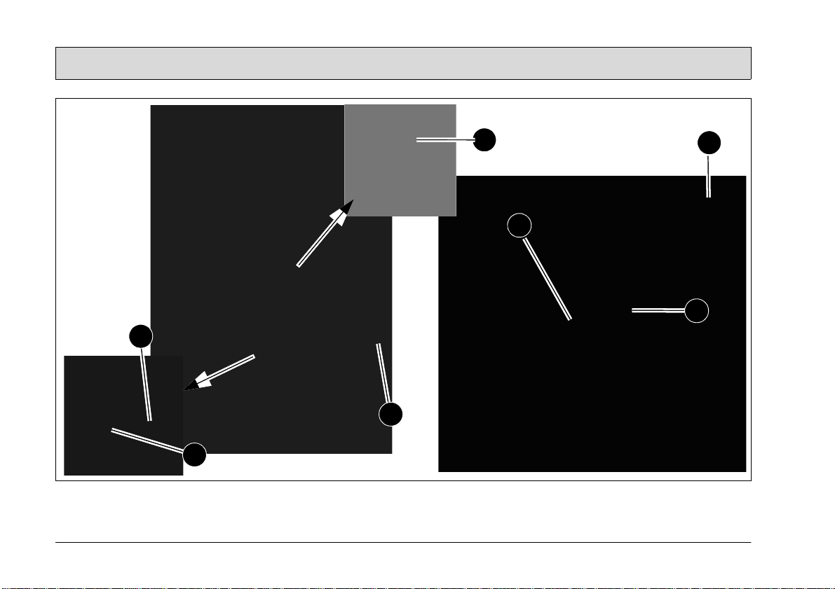
1.7 Labels on the machine
The following safety and warning labels
are attached to the machine where easily legible. Missing or illegible labels
must be replaced immediately.
Company logo (Fig. 1/1)
Rating plate (Fig. 1/2)
Filter shaker (Fig. 1/3)
Read and observe the operating
manual (Fig. 1/4)
Maximum permissible gradient
(Fig. 1/5)
Wear compensator for side brush
(Fig. 1/6)
Wear compensator for rotary brush
(Fig. 1/7)
9
Page 10
Safety Information
1
7
6
2
4
3
5
10
Fig.1
Page 11
Starting Up
2Starting Up
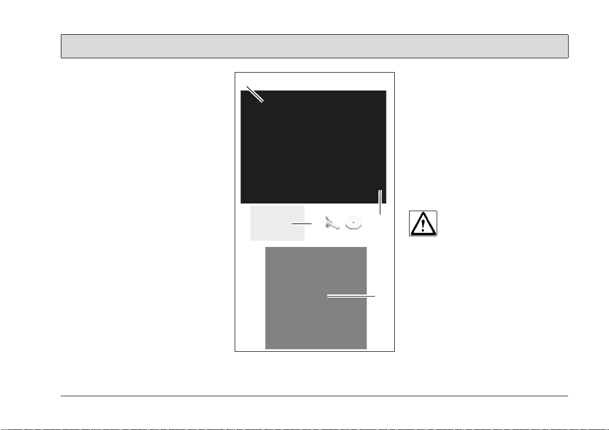
2.1 Unpacking and assembling
Open the box, two people are required
to remove the machine from the protective foil and place it on the floor.
1. Fix the side brush (Fig. 2/1) to the
axle of the side brush drive using the
wing bolt and washer supplied.
2. Loosen the two knurled screws (Fig.
2/2) holding the handle a few revolutions until the handle can be raised
and positioned. Set the handle to a
height comfortable for the user and
then tighten the knurled screws.
3. Loosen the locking bolt holding the
hood (Fig. 2/3) and pivot the hood
open.
4. Fix the disassembled cable lug (Fig.
2/4) to the corresponding battery
contact. It is possible that sparking
will occur when connecting the batteries!
5. Close the hood and lock in place with
the bolt.
6. The Kleen Sweep 25W is now
ready to operate.
2
Fig.2
2.2 Instruction
Instructions to operators are required
before putting the machine into service.
Only technicians from your local, authorized Minuteman dealer are allowed to
provide initial instruction on how to use the
machine. The manufacturing plant notifies the dealer immediately after delivering the machine and the dealer will
contact you to arrange a date for providing the initial instruction.
2.3 Initial battery charge
1
3
4
Before starting the machine up
for the first time, the batteries
to be used must be fully
charged, properly, by implementing the initial battery
charge routine. Please pay attention to the operating manual
provided with the charging unit
as well as the manual from the
battery manufacturer. Minuteman
assumes no liability for damage to the battery caused by a
fault when the battery is
charged for the first time.
11
Page 12
Starting Up
21
3
4
2.4 Prior to starting up
Carry out the following checks before
starting the machine:
1. Check the charge status of the batteries.
2. Check the levels of wear on the rotary brush and side brush.
3. Check the fill level of the sweepings
container.
2.5 Operation
Please read the Safety Information in
Chapter 1. Before switching the machine on, ensure that the drive bar (Fig.
3/3) on the handle has not been actuated.
1. Switch the machine on using the
(Fig. 3/1) button: rotary brush drive,
dust vacuum and side brush drive
are ready to operate.
2. Lower the side brush to its working
position using the lever (Fig. 3/4).
When working without the side
brush: do not lower the side brush
and press the button (Fig. 3/2) for the
side brush once. The green control
lamp goes out.
3. Actuate the drive bar (Fig. 3/3) on the
handle: the machine starts to work.
Fig.3
Start work immediately after
actuating the drive bar, otherwise imprints could be produced on the floor. Release the
drive bar when driving over
thresholds.
2.6 Stopping the machine
When the drive bar is released, the rotary brush drive, dust vacuum and side
brush drive switch off automatically.
2.7 After completing work
1. Drive to an appropriate maintenance
area.
2. Stop the machine. Raise the side
brush to its idle position and switch
the machine off.
3. Actuate the filter shaker.
4. Empty the sweepings container.
5. Check the brush space for accumulations of dirt.
6. Check the charge status of the batteries.
It is not permitted to clean the
machine with a pressure washer or steam blaster.
12
Page 13

Operation
2 3
4
6
5
3 Operation
3.1 Method of operation
The Kleen Sweep 25W is a machine
designed to sweep and clean waste
from hard floors and carpets.
The side brush (Fig. 4/1) sweeps the
dirt from corners to a position in front of
the rotary brush (Fig. 4/2). The rotary
brush sweeps the larger particle dirt
overhead into the sweepings container
(Fig. 4/3). The finer dust picked up is
drawn up by the suction turbine, fed into
the filter system (Fig. 4/4) and filtered
out. Only dust-free air is fed back into
the ambient air.
The machine is equipped with maintenance-free batteries (Fig. 4/5), a specially adapted, fully automatic battery
charger (Fig. 4/6) and a total discharge
signal transducer to protect it against
total discharge.
Please refer to the spare parts
catalogue on our internet site
at www.Minuteman.com for
accessories, such as brushes
and rotary brushes.
1
Fig.4
13
Page 14

Operation
21 34 5 6
7
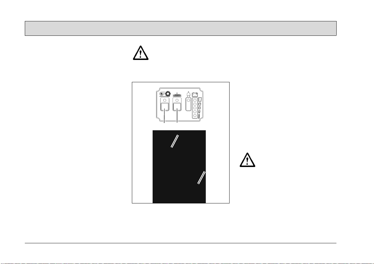
3.2 Operating and indicator
elements
3.2.1 Operating panel
1 Control lamp for rotary brush drive,
side brush drive and suction turbine
2 ON/OFF button for rotary brush
drive, side brush drive and suction
turbine
3 Control lamp for side brush drive
4 ON/OFF button for side brush drive
5 Control lamp for battery charger
operation
6 Charge control indicator
7 Drive bar
.
Fig.5
14
Page 15

Operation
Control lamp for rotary brush drive,
side brush drive and suction turbine
(Fig. 5/2)
The green control lamp indicates that
the rotary brush drive and suction turbine are ready to operate. If the rotary
brush or suction turbine are overloaded,
a safety shutdown is triggered and the
control lamp flashes.
ON/OFF button for rotary brush, side
brush and suction turbine (Fig. 5/1)
The button activates the rotary brush
drive, side brush drive and suction turbine so they are ready to operate.
The side brush drive can be switched
off separately. The suction turbine cannot be switched off separately which
prevents the dust vacuum being activated by accident.
To prevent unauthorized use
of the machine, switch the machine off using the button (Fig.
5/1).
Control lamp for side brush drive
(Fig. 5/4)
The green control lamp indicates that
the side brush drive is ready to operate.
If the side brush is overloaded, a safety
shutdown is triggered and the control
lamp flashes.
ON/OFF button for side brush drive
(Fig. 5/3)
The button can be used to switch of f the
side brush drive independently of the
rotary brush drive and to activate it for
use again.
Control lamp for battery charger
operation (Fig. 5/5)
This control lamp indicates that the batteries are being charged.
Charge control indicator (Fig. 5/6)
During the charging process, the machine's electronics system controls the
machine is not switched on inadvertently and indicates the charge status. The
battery charge status is indicated by 4
green and 1 red LED.
The battery voltage is depicted in 5 levels:
>
25.1 V = all green LEDs on
>
24.5 V = bottom 3 green LEDs on
>
23.9 V = bottom 2 green LEDs on
>
22.7 V = bottom green LED on
< 22.7 V = red battery LED flashes
Drive bar (Fig. 5/7)
The drive bar switches all the drives
which are ready to operate on or off.
The drive bar serves to prevent damage. If the drive bar is released during
operation, all the drives are switched
off.
15
Page 16

Operation
1
2
3
4
5
1
3.2.2 Operating elements on the
machine
1 Knurled screws for the handle
2 Shaking device lever
3 Sweepings container lock
4 Side brush lever
5 Charger cable flap
16
Fig.6
Page 17

Operation
Knurled screws for handle (Fig. 6/1)
The two knurled screws enable the handle to be adjusted to a comfortable
height for the user.
Shaking device lever (Fig. 6/2)
In order to clean the filter in the dust
vacuum, switch the shaking device lever several times quickly to the left and
right.
Sweepings container lock (Fig. 6/3)
Pull the lock lever up in order to remove
the sweepings container.
Side brush lever (Fig. 6/4)
Use the lever to lower or raise the side
brush.
Charger cable flap (Fig. 6/5)
The battery charger cable is located behind the flap to the right beside the operating panel. Pull the lock downwards
to open the flap.
17
Page 18

Technical Data
4 Technical Data
Machine length
Machine height (handle folded) cm 60
Machine width cm 70
Working width cm 60
Load capacity, sweeper's container kg 25
Rotary brush width cm 40
Rotary brush diameter cm 19
Area coverage, theoretic m²/h 2400
Sweeper's container volume Liter 40
Filter surface m² 1,2
Nominal voltage V24
Power consumption, rotary brush drive W 210
Power consumption, side brush drive W 48
Power consumption, suction turbine drive W 60
Weight without batteries kg 36
Weight with batteries kg 51
cm 80
18
Page 19

Technical Data
Noise emission value
Sound power level (LwA) measured according to DIN EN 60335-2-72
under maximum working conditions: dB (A) 62
The sound pressure level (LpA) (at the ear of the operator) measured according
to DIN IEC 60335-2-72 under normal working conditions: dB (A) 78
Measurement inaccuracy (KpA): dB (A) 2
Vibration
The weighted effective value of acceleration, measured in accordance with DIN
EN ISO 5349, to which the upper parts of the body (hand-arm) are exposed under
normal working conditions: m/s² < 2.5
19
Page 20

Maintenance and Service
5 Maintenance and
Service
General information
It is essential to pay attention
to the information in Chapter
"Safety Information" before
completing any service or
maintenance work!
By adhering to the maintenance work
recommended by us, you can be sure
that the machine is always ready to be
put into operation.
Maintenance and repair work necessary on a daily and weekly basis can be
carried out by an operator trained to
complete the work, all other Minuteman
system maintenance may only be completed by personnel who are
correspondingly qualified and trained.
Please contact your nearest Minuteman
service center or Minuteman authorized
dealer. Failure to observe this annuls any
rights to claims under the terms of
guarantee in respect of resulting damage
or consequential damage.
Always specify the serial number in the
case of inquiries and spare parts orders, refer to section 1.7 - Rating plate.
20
5.1 Minuteman system maintenance
The Minuteman system maintenance:
• ensures that the Minuteman machine
is always ready for operation (preventive maintenance),
• minimizes operating costs, maintenance and repair costs,
• ensures the machine has a long service life.
Minuteman system maintenance provides
individual modules explaining the special
technical work to be carried out and
prescribes the intervals at which the
work should be performed. Parts to be
replaced for the individual maintenance
tasks are defined and provided in spare
parts kits.
Minuteman system maintenance, customer
Work to be carried out by the customer
according to the service and maintenance instructions in the operating
manual (daily and weekly). The driver/
operator receives proper instruction
when the machine is delivered.
Minuteman system maintenance I:
(every 125 operating hours)
Completed by technical experts from an
authorized Minuteman service center in
accordance with the specific machine system maintenance using spare parts kits.
Minuteman system maintenance II:
(every 250 operating hours)
Completed by technical experts from an
authorized Minuteman service center in
accordance with the specific machine system maintenance using spare parts kits.
Minuteman system maintenance III/S:
(every 500 operating hours, safety
check)
Completed by technical experts from an
authorized Minuteman service center in
accordance with the specific machine system maintenance using spare parts kits.
Completion of all legally prescribed,
safety-related tests in accordance with
UVV-BGV-TÜV-VDE
Page 21

Maintenance and Service
5.2 Proof of Maintenance
Handover
Upgrading
Test drive
Handover to customer
Instruction
completed on:
at _________________ operating hours
System Maintenance I
125 operating hours
Workshop Stamp
completed on:
at _________________ operating hours
System Maintenance II
250 operating hours
Workshop Stamp
completed on:
at _________________ operating hours
System Maintenance I
375 operating hours
Workshop Stamp
completed on:
at _________________ operating hours
System Maintenance
III/S
500 operating hours
Workshop Stamp
completed on:
at _________________ operating hours
System Maintenance
III/S
1000 operating hours
Workshop Stamp
completed on:
at _________________ operating hours
System Maintenance I
625 operating hours
Workshop Stamp
completed on:
at _________________ operating hours
System Maintenance I
1125 operating hours
Workshop Stamp
completed on:
at _________________ operating hours
System Maintenance II
750 operating hours
Workshop Stamp
completed on:
at _________________ operating hours
System Maintenance II
1250 operating hours
Workshop Stamp
completed on:
at _________________ operating hours
System Maintenance I
875 operating hours
Workshop Stamp
completed on:
at _________________ operating hours
System Maintenance I
1375 operating hours
Workshop Stamp
completed on:
at _________________ operating hours
21
Page 22

Maintenance and Service
5.3 Maintenance Plan
Minuteman routine maintenance
The following maintenance work must
be completed by the customer at the intervals stipulated.
Activity
Check the battery charge; recharge if necessary o
Empty the sweeper's container o
Clean the brush space o
Check the filter in the dust vacuum; clean, if necessary o
Check the rotary brush and side brush; clean, if necessary o
Check the sweeping pattern; readjust, if necessary o
Check the sealing strips on the rotary brush for signs of wear; clean, if necessary o
Check the gasket on the sweeper's container o
Check the function of the suction turbine o
Check the sweeper's container lock o
Test drive and function test o
Interval
Daily Weekly
22
Page 23

Maintenance and Service
Minuteman routine maintenance I
The following maintenance work must
be completed by an authorized Minuteman
service center.
Activity
Interval
Every 125 operating hours
Check the rotary brush and side brush; change, if necessary o
Check the sweeping pattern; readjust, if necessary o
Check the gasket on the filter supporting frame; change, if necessary o
Check the function of the drive bar o
Check the condition of the tires o
Test drive and function test o
23
Page 24

Maintenance and Service
Minuteman routine maintenance II
The following maintenance work must
be completed by an authorized Minuteman
service center.
Activity
Every 250 operating hours
All maintenance work in accordance with Minuteman routine maintenance I o
Check the function of the charger o
Check the function of the operating panel o
Check the steering castor in respect of its running surface and bearing play; change,
if necessary
Check the filter in the dust vacuum; change the filter if necessary o
Check the running surface of the wheels; change, if necessary o
Check the sweepings container lock o
Test drive and function test o
24
Interval
o
Page 25

Maintenance and Service
Minuteman routine maintenance III/S
(safety check)
The following maintenance work must
be completed by an authorized Minuteman
service center at least once a year.
Activity
Every 500 operating hours
All maintenance work in accordance with Minuteman routine maintenance II o
Check the suction turbine for signs of wear; change, if necessary o
Clean the side brush drive from coal dust, check the carbon brushes run smoothly
and for signs of wear; change the carbon brushes, if necessary
Clean the rotary brush drive from coal dust, check the carbon brushes run smoothly
and for signs of wear; change the carbon brushes, if necessary
Check the rotary brush timing belts fro signs of wear; change, if necessary o
Check the rotary brush bearing in terms of play and for signs of wear; change, if nec-
essary
Check the wheel bearings in terms of play and for signs of wear; change, if neces-
sary
Test drive and function test o
Interval
o
o
o
o
25
Page 26

Maintenance and Service
142
3
7
8
9
5
6
5.4 Battery system
1 Battery indicator for charger
2 Charge control indicator
3 Charger
4 Flap for charger mains power cable
5 Connection cable
6 Lashing straps
7 Batteries
8Hood
9 Connection plan
Batteries may only be handled
and changed by properly
skilled maintenance personnel.
The charge control indicator
(Fig. 7/2) indicates the charge
status of the batteries during
operation. When the batteries
are discharged, the red LED
flashes. The machine functions are restricted. Charge the
batteries immediately!
26
Fig.7
Page 27

Maintenance and Service
5.4.1 Charging batteries
The charge control indicator (Fig. 7/2)
indicates the charge status of the batteries during operation. The batteries
must be charged immediately the red
LED lights up. The batteries (Fig. 7/7)
are charged using the integrated battery charger (Fig. 7/3). The charger is
connected by means of the power cable
(Fig. 7/4). While the battery is being
charged, the battery indicator on the
charger (Fig. 7/1) lights up.
Before starting the machine up
for the first time, the batteries
to be used must be fully
charged, properly, by implementing the initial battery
charge routine. Minuteman
assumes no liability for damage
to the battery caused by a fault
when the battery is charged
for the first time.
5.4.2 Total discharge signal transducer (TSG)
The machine is equipped with a total
discharge signal transducer to protect
the batteries against total discharge.
The total discharge signal transducer is
integrated in the electronics. If other
batteries are used, the total discharge
signal transducer must be adjusted.
The total discharge signal
transducer may only be adjusted by an authorized Minuteman
service center.
5.4.3 Servicing the driving batteries
Never leave discharged batteries lying
around; recharge them immediately!
For information on servicing driving batteries, refer to operating manual 88-60-
2556.
5.4.4 Removing the batteries
1. Park the machine on a level area of
floor.
2. Switch off the machine.
3. Loosen the locking bolt holding the
hood (refer to Figure 3) and pivot the
hood open.
4. Slacken the lashing straps (Fig. 7/6).
5. Disconnect the connection cable
(Fig. 7/5) from the batteries and remove the batteries.
5.4.5 Inserting the batteries
Only the special batteries approved by Minuteman may be
installed at the prescribed
position.
1. Install the two lower batteries in the
battery holder in accordance with
Figure 6.
2. Lay the rubber mat on the batteries.
3. Place the other two batteries on the
rubber mat.
4. Tighten the lashing straps (Fig. 7/6).
5. Connect the battery poles to the connection cables enclosed in the accessories kit in accordance with the
connection plan (Fig. 7/9).
It is possible that sparking will occur
when connecting the batteries! Check a
firm fit!
6. Close the hood (Fig. 7/8) and lock in
place with the locking bolt on the
frame.
5.4.6 Disposing of batteries
Used batteries with the recycling symbol contain reusable commodities. In
accordance with symbol with the
crossed out bin, these batteries must
not be disposed of in domestic waste.
Return and recycling must be agreed
on with Minuteman's authorized dealer
in accordance with § 8 BattV (Battery
Directive)!
27
Page 28

Maintenance and Service
1
3
2
5
467
5.5 Side brushes
1 Side brushes
2 Wing bolt
3Carrier
4Hood
5 Adjusting bolt
6 Counternut
7 Locking bolt
Fig.8
28
Page 29

Maintenance and Service
10:00
4:00
5.5.1 Changing the side brush
Check the side brush (Fig. 8/1) weekly
and change in the case of wear.
1. Switch the machine off and lay it on
its side.
2. Remove the wing bolt (Fig. 8/2) with
the washer from underneath the side
brush (Fig. 8/1).
3. Pull the side brush off.
4. Position the new side brush on the
carrier(Fig. 8/3) and fix in place with
the wing bolt and washer.
5.5.2 Setting the sweeping pattern
In the case of brush wear, and after
changing the side brush (Fig. 8/1), readjust the sweeping pattern.
1. Switch the machine off, u nscrew the
locking bolt (Fig. 8/7) and open the
hood (Fig. 8/4).
2. Loosen the counternut (Fig. 8/6) and
adjust the sweeping pattern by turning the adjusting bolt (Fig. 8/5) clockwise and counterclockwise so that it
touches the floor.
3. Tighten the counternut again and
close the hood.
4. Switch the machine on and allow the
side brush to run while standing still
for a short time.
5. Switch the machine off, raise the
front a little and pull it back.
6. Check the sweeping pattern, comparing it with a clock viewed driving
forward. When set correctly, the
sweeping pattern must make an impression on the floor between approx. 10:00 and 4:00 o' clock.
7. Repeat the process, if necessary,
until the sweeping pattern is set correctly.
8. Close the hood (Fig. 8/4) and screw
the locking bolt (Fig. 8/7) back in.
29
Page 30

Maintenance and Service
2 31
4
4
4
4
5
6
7
8
5.6 Rotary brush
1 Rotary brush
2 Fillister head self-tapping screws
3 Rotary brush segment
4 Sealing strips
5 Sweeping pattern adjusting lever
6 Timing belt
7Hood
8 Locking bolt
30
Fig.9
Page 31

Maintenance and Service
5.6.1 Cleaning the brush space
The brush space with rotary brush (Fig.
9/1) and gaskets (Fig. 9/4) must be
checked daily for signs of dirt and
cleaned, if necessary.
5.6.2 Changing the rotary brush
The rotary brush (Fig. 9/1) must be
checked weekly and changed in the
case of wear.
1. Switch the machine off and lay it on
its side.
2. Loosen the six fillister head screws
(Fig. 9/2) in the rotary brush and remove the two roller segments.
3. Install the two new roller segments
and fix in place with the fillister head
screws.
4. After changing the rotary brush, readjust the sweeping pattern as necessary.
5.6.3 Setting the sweeping pattern
In the case of brush wear, and after
changing the rotary brush (Fig. 9/1), readjust the sweeping pattern.
1. Switch the machine off, u nscrew the
locking bolt (Fig. 9/8) and open the
hood (Fig. 9/7).
2. Loosen the wing nut on the adjusting
lever (Fig. 9/6) and adjust the
sweeping pattern using the adjusting
lever (Fig. 9/5) by pivoting it up and
down until it touches the floor.
3. Tighten the wing nut again and close
the hood.
4. Switch the machine on and allow the
rotary brush to run while standing
still for a short time.
5. Switch the machine off, raise the
front a little and pull it back.
6. When adjusted correctly, there must
be an approx. 50 mm wide sweeping
pattern on the floor which has parallel sides.
7. Repeat the process, if necessary,
until the sweeping pattern is set correctly.
8. Close the hood (Fig. 9/7) and screw
the locking bolt (Fig. 9/8) back in.
5.6.4 Changing the sealing strips
The four sealing strips (Fig. 9/4) must
be checked weekly and changed in the
case of wear.
1. Switch the machine off and lay it on
its side.
2. Remove all four sealing strips (Fig.
9/2) with holders.
3. Loosen the screws in the holders
and remove the damaged sealing
strips.
4. Fix the new sealing strips on the
holders and reinstall them.
5. Adjust the sealing strips so that they
touch the floor lightly.
5.6.5 Changing the timing belt
The timing belt (Fig. 9/6) must be
checked every 500 operating hours and
changed in the event of wear.
1. Switch the machine off, unscrew the
locking bolt (Fig. 9/8) and open the
hood (Fig. 9/7).
2. Slacken the timing belt (Fig. 9/6) using the tension pulley and remove
the belt.
3. Slacken the tension pulley and install
the new timing belt. The timing belt is
automatically tensioned by means of
a tension spring.
4. Close the hood (Fig. 9/7) and screw
the locking bolt (Fig. 9/8) back in.
31
Page 32

Maintenance and Service
1
6
3
4
5
2
5.7 Dust vacuum
1 Filter
2 Sealing strip
3 Filter support frame
4 Shaking device
5 Wing bolts
6 Holder
32
Fig.10
Page 33

Maintenance and Service
5.7.1 Cleaning the filter
Clean the filter (Fig. 10/1) in the dust
vacuum as necessary using the shaking device (Fig. 10/4). In the case of extreme accumulation of dirt, clean the
filter as follows:
1. Switch the machine off and remove
the sweeper's container.
2. Loosen the wing bolts (Fig. 10/5).
Pivot the filter support frame (Fig. 10/
3) down and remove it.
3. Remove the filter from the filter support frame.
4. Beat the filter clean or use a vacuum
cleaner. Be careful not to damage
the filter ribs!
5. Insert the correct side of filter in the
filter support frame. The sealing strip
(Fig. 10/2) must point towards the
suction turbine!
6. Hook the filter support frame in the
holder (Fig. 10/6) and fix in place
with the wing bolts.
7. Reinstall the sweeper's container.
5.7.2 Changing the filter
Check the filter (Fig. 10/1) every 250
operating hours for signs of wear and
change it as necessary.
1. Switch the machine off and remove
the sweeper's container.
2. Unscrew the wing bolts (Fig. 10/5).
Pivot the filter support frame (Fig. 10/
3) down and remove it.
3. Remove the filter from the filter support frame.
4. Insert the correct side of the new filter in the filter support frame. The
sealing strip (Fig. 10/2) must point
towards the suction turbine!
5. Hook the filter support frame in the
holder (Fig. 10/6), if necessary, and
fix in place with the wing bolts.
6. Reinstall the sweeper's container.
33
Page 34

Maintenance and Service
1
3
2
4
5.8 Sweeper'ss container
1 Sweeper's container
2 Locking mechanism
3Seal
4 Handle
34
Fig.11
Page 35

Maintenance and Service
5.8.1 Emptying the sweepings container
Check the fill level of the sweeper's
container (Fig. 10/1) at regular intervals
(max. load capacity 25 kg) and empty
as necessary.
1. Switch the machine off and pull the
locking mechanism (Fig. 10/2) on the
sweeper's container (Fig. 10/1) upwards.
2. Pull the sweeper's container to the
rear out of the machine using the
handle (Fig. 10/4) and dispose of the
waste according to the applicable
environmental laws.
3. Reinstall the sweeper's container
and press it against the locking
mechanism until it audibly latches
into place.
5.8.2 Changing the seal
Check the seal (Fig. 10/3) weekly for
signs of wear and change it as necessary.
1. Switch off the machine and pull the
locking mechanism (Fig. 10/2) on the
sweeper's container (Fig. 10/1) upwards.
2. Pull the sweepings container (Fig.
10/3) to the rear and out of the ma-
chine using the handle (Fig. 10/4).
3. Pull the seal on the sweeper's container from the filter support frame.
Install a new seal.
4. Reinstall the sweeper's container
and press it against the locking
mechanism until it audibly latches
into place.
35
Page 36

Maintenance and Service
36
Page 37

EC-Declaration of Conformity (according to Directive 98/37/EC)
Minuteman International Inc.
14N845 U.S. Route 20
PINGREE GROVE, IL. 60140-8893
U.S.A.
declare under our sole responsibility,
that the product
Minuteman Kleen Sweep 25W
Type: 6258
to which this declaration relates, corresponds to the relevant basic safety and
health requirement of the Directive 98/
37/EC, and to the requirements of the
other relevant Directives:
89/336/EEC.
For the relevant implementation of the
safety and health requirements mentioned in the Directives, the following standard (s) and / or technical specification
(s) has (have) been respected:
DIN EN 60335-2-72
DIN EN 61000-6-2
DIN EN 61000-6-3
Bad Oldesloe, 21.01.2009
Bernd Heilmann
Managing director
37
Page 38

Minuteman International Made Simple Commercial Limited Warranty
Minuteman International, Inc. warrants to the original purchaser/user that this product is free from defects in workmanship and materials under
normal use. Minuteman will, at its option, repair or replace without charge, parts that fail under normal use and service when operated and
maintained in accordance with the applicable operation and instruction manuals.
All warranty claims must be submitted through and approved by factory authorized repair stations.
This warranty does not apply to normal wear, or to items whose life is dependent on their use and care, such as belts, cords,switches, hoses,
rubber parts, electrical motor components or adjustments. Parts not manufactured by are covered by and subject to the warranties and/or
guarantees of their manufacturers. Please contact Minuteman for procedures in warranty claims against these manufacturers.
Special warning to purchaser -- Use of replacement filters and/or prefilters not manufactured by Minuteman or its designated licensees, will void
all warranties expressed or implied.
A potential health hazard exists without original equipment replacement.
All warranted items become the sole property of Minuteman or its original manufacturer, whichever the case may be.
Minuteman disclaims any implied warranty, including the warranty of merchantability and the warranty of fitness for a particular purpose.
Minuteman assumes no responsibility for any special, incidental orconsequential damages.
This limited warranty is applicable only in the U.S.A. and Canada, and is extended only to the original user/purchaser of this product. Customers
outside the U.S.A. and Canada should contact their local distributor for export warranty policies. Minuteman is not responsible for costs or repairs
performed by persons other than those specifically authorized by Minuteman. This warranty does not apply to damage from transportation,
alterations by unauthorized persons, misuse or abuse of the equipment, use of non-compatible chemicals, or damage to property, or loss of
income due to malfunctions of the product.
Page 39

If a difficulty develops with this machine, you should contact the dealer from whom it was purchased.
This warranty gives you specific legal rights, and you may have other rights which vary from state to state. Some states do not allow the exclusion
or limitation of special, incidental or consequential damages, or limitations on how long an implied warranty lasts, so the above exclusions and
limitations may not apply to you.
Cord Electric Group Three years parts, two years labor, ninety days travel (Not to exceed two hours)
Exceptions Port-A-Scrub, one year parts, six months labor
MPV 13, one year parts
MPV 14 and 18, two years parts, one year labor
Rapid Air blower, one year parts, one year labor
Pneumatic Vacuums, three years parts, one year labor
EX 12 and EX 12H, one year parts, one year labor
Battery Operated Group Three years parts, two years labor, ninety days travel
Exceptions Sweepers, one year parts, one year labor, ninety days travel
Replacement parts Ninety days
Batteries 0-3 months replacement, 4-12 months pro-rate
Polypropylene Plastic Tanks Ten years, no additional labor
(Not to exceed two hours)
(Not to exceed two hours)
Page 40

Excellence Meets Clean
Minuteman International Inc. · 14N845 U.S. Route 20 · Pingree Grove, II. 60140-8893 · U.S.A.
Phone: 630 627-6900 · Fax 630 627-1130
988729UM REV * 02/09
 Loading...