

Page 1
M I N T R O N I X C O M P U T E R S O L U T I O N S
User’s Guide
M P 5 0 0 0 I 5 V 2 A L L - IN- O N E T O U C H
S C R E E N C O M P U T E R S Y S T E M
Page 2

This manual is intended to provide both general information on small point of sales
technology and technical specifications of the MP5000i5v2 computer. The information
provided herein is of a proprietary nature to the original manufacturer and may not
be distributed without express written consent from an officer of the company. This
manual has been supplied in confidence and is intended for use by authorized
recipients only. This manual may not be copied or reproduced in whole or in part, nor
may its contents be revealed in any manner to any person other than the authorized
personnel.
This document has been prepared with the utmost effort to insure the information
contained within is accurate and complete. However, the original manufacturer
reserves the right to make product improvements or changes at any time without
advanced notice. Furthermore, the original manufacturer assumes no liability arising
from use of the products described herein. Working with the MP5000i5v2
computer involves hazardous levels of voltages and can present serious shock hazard.
Work should only be performed by appropriately qualified technical personnel.
The original manufacturer’s products are not authorized or designed for use in critical
life saving equipment. The original manufacturer’s products are warranted for one
year from the date of purchase against component and workmanship defects. The
original manufacturer’s Return Merchandise Authorization (RMA) policy requires the
user to obtain an RMA # prior to sending back any item to be repaired or replaced.
Replacement or repair will be free of charge for all items under warranty only when
the merchandise is returned to the original manufacturer, not a third-party repair
depot. Returned goods need to have pre-paid freight along with a copy of the original
invoice; collect freight items will not be accepted and will be returned to sender. For
specific return circumstances and/or warranty information, please contact your
dealer.
All trademarks mentioned herein belong to their respective companies.
Copyright: 2018
Page 3

M I N T R O N I X C O M P U T E R S O L U T I O N S
124 Old Mill Road, Suite H
Greenville, SC 29607
855-672-6464
Version 1-2018
Page 3
Table of Contents
1.0
Introduction
5
2.0
Standard Features
5
3.0
Input/Output
6
4.0
Graphics
6
5.0
Touch Screen
7
6.0
Power Supply
7
7.0
Environment
7
8.0
Physical Dimensions
7
9.0
Optional Accessories
7
10.0
Setup Installation
8
10.1
Unpacking
8
10.2
Site Selection
8
10.3
Installation Checklist
8-9
11.0
Bios Introduction
9
11.1
Bios Setup
9
11.2
Bios Main Menu
10
11.3
Bios Operation
11
11.4
Advanced Bios Features
11
12.0
ACPI Settings
11
13.0
PCH-FW Configuration
11
14.0
Super IO Configuration
12
15.0
H/W Monitor
12
16.0
S5 RTC Wake Settings
12
17.0
Serial Port Console Redirection
12
18.0
CPU Configuration
12
19.0
Platform Misc. Configuration
13
20.0
SATA Configuration
13
21.0
Network Stack Configuration
14
22.0
CSM Configuration
14
23.0
USB Configuration
14
24.0
Chipset Configuration
15
25.0
System Agent Configuration
15-16
Page 4

M I N T R O N I X C O M P U T E R S O L U T I O N S
124 Old Mill Road, Suite H
Greenville, SC 29607
855-672-6464
Version 1-2018
Page 4
26.0
PCH-IO Configuration
16-17
27.0
Security Setting-Secure Boot
18
27.1
Key Management
18
27.2
Boot Setting
19
28.0
Save & Exit Configuration
18-19
29.0
CMOS Clear
20
30.0
Installing Software & Drivers
20
30.1
Operating Systems
20
30.2
Video Driver
20
30.3
Audio Driver
21
30.4
Network Driver
21
30.5
Touch Screen Driver
21
30.6
Tuning Touch Screen
21
30.7
Other Applications
21
31.0
Troubleshooting
22
31.1
Initial Inspection
22
31.2
Peripherals Configuration
22
31.3
Connection Problems
23
32.0
Standard IRQ Settings
23
33.0
Optional MSR
23
33.1
Reader Test
24
33.2
Changing Configuration
24
33.3
Optional Character Display
24
33.4
Power-Up Initialization
24
34.0
Communications Settings
25
34.1
Character Codes
25
Page 5

M I N T R O N I X C O M P U T E R S O L U T I O N S
124 Old Mill Road, Suite H
Greenville, SC 29607
855-672-6464
Version 1-2018
Page 5
1.0 Introduction
The All-in-One touch screen computer with adjustable viewing angle has the flexibility
of a PC-based computer and architecture combined with advanced LCD and touch
screen technology to form a low cost, small-sized computer that runs all PC-based
software. Its unique design allows for ease of use with any applications. With
networking capability, this computer is ideal for information kiosk, point of
sales, and practically anything one can imagine.
2.0 Standard Features
Processor
LGA1151 Intel desktop Core i7/i5/i3/Pentium/Celeron
processors compliant
Bios
AMI EFI 128 Mbit SPI
Memory
Up to 32 GB in 2 slots 260-pin SODIMM sockets. Supports dual
channel DDR4 2133 MHz SDRAM
Chipset
Intel® H110
Storage Devices
SATA hard disk drive interface:
• Three on-board SATA connector with data transmission
rates of up to 600 MB
• One mSATA with Mini PCIe interface with high speed
data transmission
Watchdog Timer
Can generate a system reset. The watchdog timer is
programmable, with each unit equal to one second or one
minute (255 levels).
Page 6

M I N T R O N I X C O M P U T E R S O L U T I O N S
124 Old Mill Road, Suite H
Greenville, SC 29607
855-672-6464
Version 1-2018
Page 6
3.0 Input/Output
Serial
Two serial ports, 1 x RS-232 & 1 x RS-232/422/485
Parallel
AMI EFI 128 Mbit SPI
Ethernet
Supports dual 10/100/1000 Mbps Ethernet port (s) via PCI
Express x1 bus which provides 500 MB/s data transmission
rates.
Controller: LAN1/2: Realtek 8111G x 2
Keyboard/Mouse
Supports one standard PS/2 keyboard, one standard PS/2
mouse
USB
Supports up to ten USB ports with transmission rates up to
625 MB.
• 4 on board pin header with USB 2.0 and 4 external
ports with USB 3.0.
Note: Under Windows 7 OS, all of USB 2.0/3.0 ports are not
workable before the XHCI driver is installed. Suggest using the
PS/2 keyboard and mouse for XHCI driver install first
PCI Bus
1 PCIe x4 slot
General Purpose
8-bit general purpose Input/Output. This is a flexible parallel
interface that allows a variety of custom connections
4.0 Graphics
Display Controller
Intel® HD Graphics 530
Display
VGA: Supports VGA up to resolution 1920 x 1200 @ 60 Hz
refresh rate.
LVDS: Supports LVDS up to resolution 1920 x 1200.
HDMI: Supports HDMI up to resolution 4096 x 2304 @ 24Hz.
Display port 1.2: Supports display port up to resolution 3840 x
2160 @ 60Hz.
Display Memory
1GB maximum shared memory with 2GB and above system
memory installed
Page 7

M I N T R O N I X C O M P U T E R S O L U T I O N S
124 Old Mill Road, Suite H
Greenville, SC 29607
855-672-6464
Version 1-2018
Page 7
5.0 Touch Screen
Touch Screen
5 wire resistive technology integrated USB controller,
using mouse emulation
6.0 Power Supply
Power Supply
Voltage
+3.3 V, +5 V, +12 V, -12 V, 5 VSB “standby voltage”. 12V DC
Input
7.0 Environment
Operating
Temperature
0 ~ 60° C (32 ~ 140° F, (depending on CPU)
Storage
Temperature
-40 ~ 85° C (-40 ~ 185° F)
8.0 Physical Dimensions
Weight
0.365 kg
Board Size
170 mm x 170 mm (6.69" x 6.69")
9.0 Optional Accessories
Magnetic Stripe
Reader
1~3 track HID USB reader
Customer Display
2 lines by 20-character LCD with backlight
Barcode Scanner
CCD miniature scanner
Page 8

M I N T R O N I X C O M P U T E R S O L U T I O N S
124 Old Mill Road, Suite H
Greenville, SC 29607
855-672-6464
Page 8
Version 1-2018
10.0 Set Up and Installation of the All-in-One
10.1 Unpacking. What you should have:
✓ MP5000i5v2 computer monitor base unit
✓ Screws to attach the base unit to the computer monitor
✓ Power adapter and power cord
✓ Drivers and manual files (included on the hard drive)
10.2 Site Selection:
Consider the following when selecting sites:
✓ The area should be well ventilated
✓ Avoid glare from bright overhead lighting
✓ The system should be placed on a hard surface
✓ There should be easy access for power and other cabling requirements
10.3 Installation Checklist:
Route cables through the cast alloy stand and position the cables to the
side of the stand
Insert stand front tabs into slots on back of MP5000I5v2
Page 9

M I N T R O N I X C O M P U T E R S O L U T I O N S
124 Old Mill Road, Suite H
Greenville, SC 29607
855-672-6464
Page 9
Version 1-2018
Remove the screw on the center top of the MP5000I5v2 and use it to
secure the stand to the computer
Route all other peripheral cables through the stand
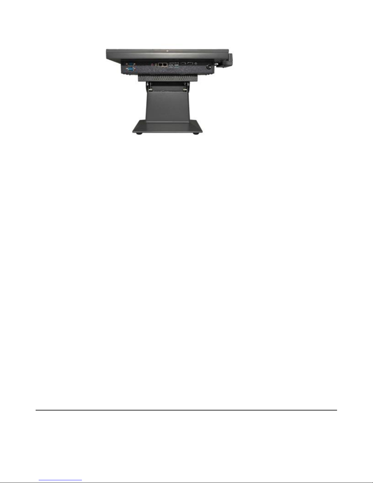
Connect them to the MP5000i5v2 computer. Set the computer in upright
position.
Connect all the peripherals to the cables
Turn the computer on
Install operating system software (pre-installed if purchased with system)
Install software driver’s
Install application software
11.0 BIOS Introduction
With the AMI BIOS Setup program, you can modify BIOS settings and control the
special features of your computer. The Setup program uses several menus for
making changes and turning special features on or off. This chapter describes the
basic navigation of the MP5000i5v2 setup screens.
11.1 BIOS Setup
The MP5000i5v2 computer has the AMI BIOS built in, with a CMOS SETUP utility that
allows users to configure required settings or to activate certain system features.
The CMOS SETUP saves the configuration in the CMOS RAM of the motherboard.
When the power is turned off, the battery on the board supplies the necessary power
to preserve the CMOS RAM.
When the power is turned on, press the <Del> button during the BIOS POST (PowerOn Self-Test) to access the CMOS SETUP screen.
Page 10
M I N T R O N I X C O M P U T E R S O L U T I O N S
124 Old Mill Road, Suite H
Greenville, SC 29607
855-672-6464
Page 10
Version 1-2018
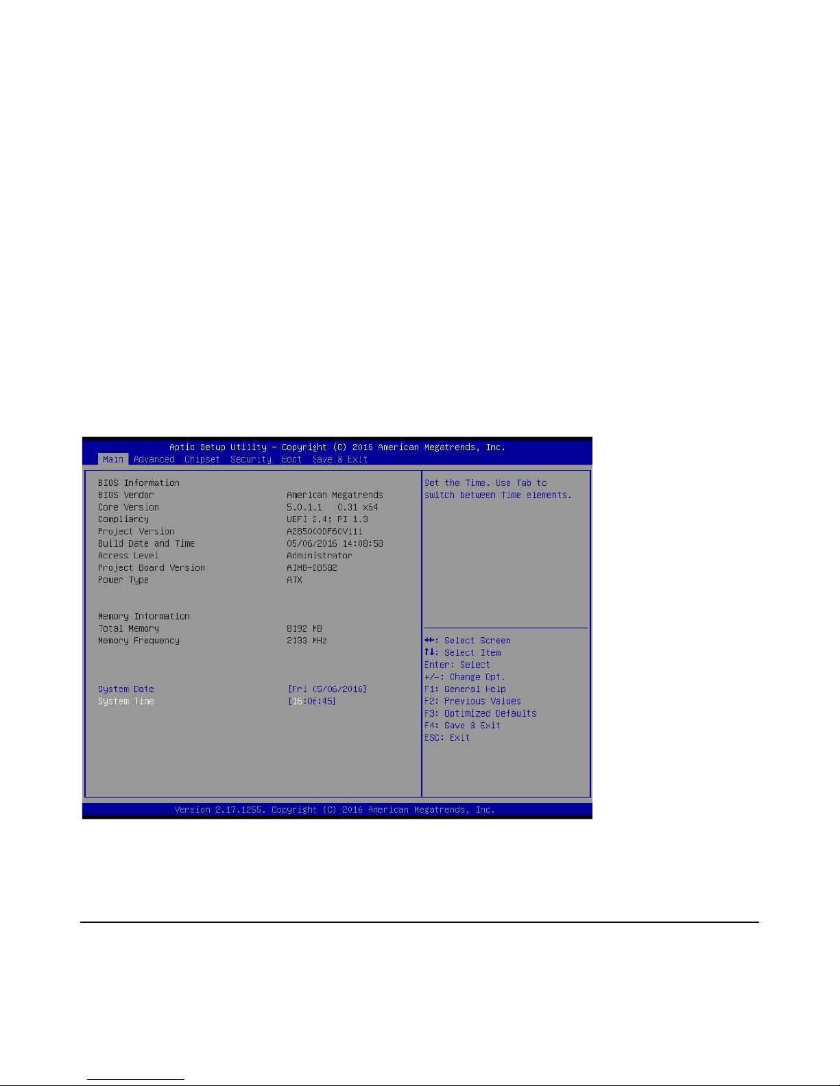
11.2 BIOS Main Menu
Press <Del> to enter AMI BIOS CMOS Setup Utility, the Main Menu will appear on
the screen. Use arrow keys to select among the items and press <Enter> to accept or
enter the sub-menu.
Control Keys
< ↑ >< ↓ >< ← >< → > Move to select item
<Enter> Select Item
<Esc> Exit
<Page Up/+> Increase the numeric value or make changes
<Page Down/-> Decrease the numeric value or make changes
<F1> General help
<F2> Previous Values
<F3> Optimized Defaults
<F4> Save & Exit
Page 11

M I N T R O N I X C O M P U T E R S O L U T I O N S
124 Old Mill Road, Suite H
Greenville, SC 29607
855-672-6464
Page 11
Version 1-2018
11.3 BIOS Operation
The Main BIOS setup screen has two main frames. The left frame displays all the
options that can be configured. Grayed-out options cannot be configured; options in
blue can. The right frame displays the key legend.
Above the key legend is an area reserved for a text message. When an option is
selected in the left frame, it is highlighted in white. Often a text message will
accompany it.
Use the “System time / System date” option to change the system time and date.
Highlight System Time or System Date using the <Arrow> keys. Enter new values
through the keyboard. Press the <Tab> key or the <Arrow> keys to move between
fields. The date must be entered in MM/DD/YY format. The time must be entered in
HH:MM:SS format.
11.4 Advanced BIOS Feature
Select the “Advanced” tab from the setup screen to enter the Advanced BIOS Setup
screen. You can select any of the items in the left frame of the screen, such as CPU
Configuration, to go to the sub menu for that item. You can display an Advanced BIOS
Setup option by highlighting it using the <Arrow> keys. All Advanced BIOS Setup
options are described in this section. The Advanced BIOS Setup screen is shown
below. The sub menus are described on the following pages.
12.0 ACPI Settings
Enable ACPI Auto Configuration [ Disabled ]
Enable Hibernation [ Enabled ] Enables or disables the system’s ability to
Hibernate (OS/S4 Sleep State). This option may be not effective with some OS.
ACPI Sleep State [ S3 (Suspend to RAM) ]. Select ACPI sleep state the system
will enter when the SUSPEND button is pressed.
Lock Legacy Resources [ Disabled ]
13.0 PCH-FW Configuration
ME Unconfig on RTC Clear Status [ Enabled ]
ME State [ Enabled ]
Page 12

M I N T R O N I X C O M P U T E R S O L U T I O N S
124 Old Mill Road, Suite H
Greenville, SC 29607
855-672-6464
Page 12
Version 1-2018
14.0 Super IO Configuration
Serial Port 1 Configuration - Serial Port [ Enabled ]
Device Settings IO=3F8h; IRQ = 4
Change Settings [ Auto ]
Serial Port 2 Configuration - Serial Port [ Enabled ]
Device Settings IO=2F8h; IRQ = 3
Change Settings [ Auto ]
Device Mode [ RS232 ]
15.0 H/W Monitor
CPU Warning Temperature [ Disabled ]. Use this to set the CPU warning
temperature threshold. When the system reaches the warning temperature,
the speaker will beep.
ACPI Shutdown Temperature [ Disabled ]. Use this to set the ACPI shutdown
temperature threshold. When the system reaches the shutdown temperature,
it will be automatically shut down by ACPI OS to protect the system from
overheating damage.
16.0 S5 RTC Wake Settings
S5 RTC Wake Settings allows you enable or disable system wake up on alarm event.
Wake system from S5 [ Disabled ]. Enable or disable system wake on alarm
event. Select FixedTime: System will wake on the specific hr:min:sec.
17.0 Serial Port Console Redirection
Console Redirection [ Disabled ]. Enable or disable the console redirection
feature
Page 13

M I N T R O N I X C O M P U T E R S O L U T I O N S
124 Old Mill Road, Suite H
Greenville, SC 29607
855-672-6464
Page 13
Version 1-2018
18.0 CPU Configuration
The item shows your CPU specification and features (content may be different
with different CPUs).
Power Limit 3 Override [ Disabled ]. If this option is enabled, BIOS will leave the
default values for Power Limit 3 and Power Limit 3 Power Window.
Power Limit 4 Override [ Disabled ] If this option is enabled, BIOS will leave the
default values for Power Limit 4.
CPU Thermal Configuration. CPU DTOS [ Disabled ]. Disable: ACPI thermal
management uses EC reported temperature values. Enable: ACPI thermal
management use DTS SMM mechanism to obtain CPU temperature values. Out
of Spec: ACPI thermal management use EC reported temperature values and
DTS SMM mechanism is used to handle Out of Spec.
ACPI 3.0 T-States [ Disabled ]
19.0 Platform Misc. Configuration
Native PCIE Enable [ Enabled ]. Note! PCI Express Native support is only
available in Vista.
Native ASPM [ Auto ]
BOAT ACPI Table Support [ Disabled ]
PCI Delay Optimization [ Disabled ]
20.0 SATA Configuration
SATA Controllers [ Enabled ]
SATA Mode Selection [ AHCI ]
Aggressive LPM Support [ Enabled ]
Serial ATA Port 1 [ Enabled ]
Serial ATA Port 2 [ Enabled ]
Serial ATA Port 3 [ Enabled ]
mSATA [ Enabled ]
Page 14

M I N T R O N I X C O M P U T E R S O L U T I O N S
124 Old Mill Road, Suite H
Greenville, SC 29607
855-672-6464
Page 14
Version 1-2018
21.0 Network Stack Configuration
Network Stack [ Disabled ]. Enable / Disable UEFI Network Stack
22.0 CSM Configuration
CSM Support [ Enabled ]
Boot option filter [ UEFI only ]
Option ROM execution
o Network [ UEFI ]
o Storage [ UEFI ]
o Video [ UEFI ]
o Other PCI device [ UEFI ]
Note! If your HDD or other boot device is installed as Legacy mode, it may
cause a blue screen. There are 2 ways to resolve this:
1. Re-install your OS in UEFI Mode
2. Change all the settings above as " Legacy"
a. Boot option filter -> Legacy Only
b. Network -> Legacy
c. Storage -> Legacy
d. Video -> Legacy
e. Other PCI devices -> Legacy
23.0 USB Configuration
Legacy USB Support [ Enabled ]. Enables support for legacy USB. Auto option
disables legacy support if no USB devices are connected.
XHCI Hand-off [ Enabled ]
USB Mass Storage Driver Support [ Enabled ]. USB hardware delays and
time-outs USB Device transfer & reset time-out and delay setting.
Mass Storage Devices [ Auto ]. Auto detect the USB
Page 15

M I N T R O N I X C O M P U T E R S O L U T I O N S
124 Old Mill Road, Suite H
Greenville, SC 29607
855-672-6464
Page 15
Version 1-2018
24.0 Chipset Configuration Setting
Select the chipset tab from the BIOS setup screen to enter the Chipset Setup screen.
Users can select any item in the left frame of the screen, such as PCI express
configuration, to go to the sub menu for that item. Users can display a Chipset Setup
option by highlighting it using the <Arrow> keys. The Chipset Setup screens are shown
below. The sub menus are described below.
25.0 System Agent (SA) Configuration
VT-d [ Enabled ]. Disable or enable VT-d capability.
Above 4GB MMIO BIOS assignment [ Disabled ]
Graphics Configuration - Graphics Turbo IMON Current [ 31 ]. Graphics turbo
IMON Current values supported (14-31 ).
o Primary Display [ Auto ]. Select which of IGFX/PEG/PCI Graphics device
should be Primary Display
o Internal Graphics [ Auto ]
o Keep IGD enabled based on the setup options.
o GTT Size [ 8MB ]
o Aperture Size [ 256MB ]
o DVMT Pre-Allocated [ 32M ]
o Select DVMT 5.0 Pre-Allocated (Fixed) Graphics Memory size used by the
o Internal Graphics Device.
o DVMT Total Gfx Mem [ 256M ]. Select DVMT5.0 Total Graphic Memory
size used by the Internal Graphics Device.
o Gfx Low Power Mode [ Enabled ]. This option is applicable for SFF only
o VDD Enable [ Enabled ]
o PM Support [ Enabled ]
o PAVP Enable [ Enabled ]
o Cdynmax Clamping Enable [ Enabled ]
o Cd Clock Frequency [ 675 MHz ]
LCD Control - LVDS Panel Type [ Disabled ]
DMI/ OPI Configuration - DMI Max Link Speed [ Auto ]. Set DMI Speed at Gen1/
Gen2/ Gen3.
Gen3 Root Port Press Value for each Lane
Gen3 Endpoint Hint value for each Lane
Gen 3 RxCLTE Control
Page 16

M I N T R O N I X C O M P U T E R S O L U T I O N S
124 Old Mill Road, Suite H
Greenville, SC 29607
855-672-6464
Page 16
Version 1-2018
PEG Port Configuration
o Enable Root Port [ Auto ]
o Max Link Speed [ Auto ]
o Detect Non-Compliance Device [ Disabled ]. Detect Non-Compliance PCI
Express Device in PEG
o Program PCIe ASPM after OpROM [ Disabled ]
o Enabled: PCIe ASPM will be programmed after OpROM.
o Disabled: PCIe ASPM will be programmed before OpROM.
o Program Static Phase1 Eq [ Enabled ]
o PEG Sampler Calibrate [ Disabled ]
Gen3 Root Port Preset value for each Lane
Gen3 Endpoint Preset value for each Lane
Gen3 Endpoint Hint value for each Lane
Gen3 RxCTLE Control
RxCTLE Override [ Disabled ]
Memory Configuration - The item shows you memory specification included RC
version, Frequency, size and voltage information etc.
o Max TOLUD [ Dynamic ]
o Maximum Value of TOLUD. Dynamic assignment would adjust TOLUD
automatically based on largest MMIO length of installed graphic
controller.
o Retrain on Fast Fail [ Enabled ]
o Memory Remap [ Enabled ]
o Fast Boot [ Enabled ]
GT- Power Management Control - RC6 (Render Standby) [ Enabled ]. Check to
enable / disable render standby supported.
26.0 PCH-IO Configuration
LAN1 Control [ Enabled ]. Enable or disable the LAN 1 controller.
LAN 2 controller [ Enabled ]. Enable or disable the LAN 2 controller.
PCIE Wake [ Disabled ]. Enable or disable PCIE Wake feature.
Deep Sleep [ Disabled ]. Enable or disable the Deep Sleep function.
High Precision Timer [ Enabled ]
Start After G3 [ Power Off ]
PCI Express Configuration
Page 17

M I N T R O N I X C O M P U T E R S O L U T I O N S
124 Old Mill Road, Suite H
Greenville, SC 29607
855-672-6464
Page 17
Version 1-2018
o PCI Express Clock Gating [ Enabled ]. Enable or disable PCI Express Clock
Gating for each root port.
o DMI Link ASPM Control [ Enabled ]. Enable or disable the control of
Active State Power Management on SA side of the DMI Link.
o Peer Memory Write Enable [ Disabled ]
o PCIe-USB Glitch W/A [ Disabled ]
PCI Express G3 Eq Lanes - Override SW EQ settings [ Disabled ]
Mini PCI Express1 - Mini PCI Express [ Enabled ]. Enable or disable PCI Express
Root Port controller.
o ASPM Support [ Auto ]
o L1 Substates [ L1.1 & L1.2 ]
o PCIe Speed [ Auto ]
Mini PCI Express2 – Mini PCI Express [ Enabled ]. Enable or disable PCI Express
Root Port controller.
o ASPM Support [ Auto ]
o L1 Substates [ L1.1 & L1.2 ]
o PCIe Speed [ Auto ]
USB Configuration - USB 2.0 & 3.0 only supported from 1 XHCI controller.
BIOS Security Configuration
o RTC Lock [ Enabled ]. Enable will lock bytes 38h-3Fh in the lower/upper
128 byte bank of RTC RAM.
o BIOS Lock [ Enabled ]
HD Audio Configuration - HD Audio [ Auto ].This item is to control detection of
the HD-Audio device.
o HAD will be unconditionally disabled=[ Disabled ]
o HAD will be unconditionally enabled=[ Enabled ]
o HAD will be enabled if present, disabled otherwise=[ Auto ]
Page 18

M I N T R O N I X C O M P U T E R S O L U T I O N S
124 Old Mill Road, Suite H
Greenville, SC 29607
855-672-6464
Page 18
Version 1-2018
27.0 Security Setting-Secure Boot Menu
Secure Boot [ Disabled ]. Secure Boot can be enabled if 2 conditions below:
1. System is running in user mode with enrolled Platform Key (PK)
2. CSM function is disabled
Secure Boot Mode [ Custom ]
27.1 Key Management
Provision Factory Default Keys [ Disabled ]. Install factory default Secure Boot
Keys when system is in setup mode.
27.2 Boot Setting
Setup Prompt Timeout [ 1 ]. User the <+> and <-> keys to adjust the number of
seconds to wait for setup activation key.
Bootup NumLock State [ On ]. On or Off power on state for the NumLock
Quiet Boot [ Disabled ]. If this option is set as disabled, the BIOS displays
normal POST messages. If set as enabled, an OEM logo is shown instead of POST
messages.
Boot Option Priorities. Choose boot priority from boot device
28.0 Save & Exit Configuration
Save Changes and Exit -When users have completed system configuration,
select this option to save changes, exit BIOS setup menu and reboot the
computer to take effect all systemconfiguration parameters.
1. Select Exit Saving Changes from the Exit menu and press <Enter>. The
following message appears: Save Configuration Changes and Exit Now?
2. Select [Ok] or [Cancel]
Discard Changes and Exit - Select this option to quit Setup without making any
permanent changes to the system configuration.
1. Select Exit Discarding Changes from the Exit menu and press <Enter>. The
following message appears: Discard Changes and Exit Setup Now? [Ok] or
[Cancel]
2. Select [Ok] to discard changes and exit. If you want to discard the changes,
select [Discard Changes] from the Exit menu and press <Enter>.
Page 19

M I N T R O N I X C O M P U T E R S O L U T I O N S
124 Old Mill Road, Suite H
Greenville, SC 29607
855-672-6464
Page 19
Version 1-2018
Save Changes and Reset - When users have completed system configuration,
select this option to save changes, exit BIOS setup menu and reboot the
computer to take effect all system configuration parameters.
1. Select Exit Saving Changes from the Exit menu and press <Enter>. The
following message appears: Save Configuration Changes and Exit Now? [Ok] or
[Cancel]
2. Select [Ok] or [Cancel]
Discard Changes and Reset - Select this option to quit Setup without making any
permanent changes to the system configuration.
1. Select Reset Discarding Changes from the Exit menu and press <Enter>. The
following message appears: Discard Changes and Exit Setup Now? [Ok] or
[Cancel]
2. Select Ok to discard changes and reset. Discard Changes Select Discard
Changes from the Exit menu and press <Enter>.
Restore Default - The BIOS automatically configures all setup items to optimal
settings when users select this option. Defaults are designed for maximum
system performance but may not work best for all computer applications. Do
not use the Defaults if the user's computer is experiencing system configuration
problems. Select Restore Defaults from the Exit menu and press <Enter>.
Save as User Default - Save the all current settings as a user default.
Restore User Default - Restore all settings to user default values.
Boot Override - Shows the boot device types on the system.
Page 20
M I N T R O N I X C O M P U T E R S O L U T I O N S
124 Old Mill Road, Suite H
Greenville, SC 29607
855-672-6464
Page 20
Version 1-2018
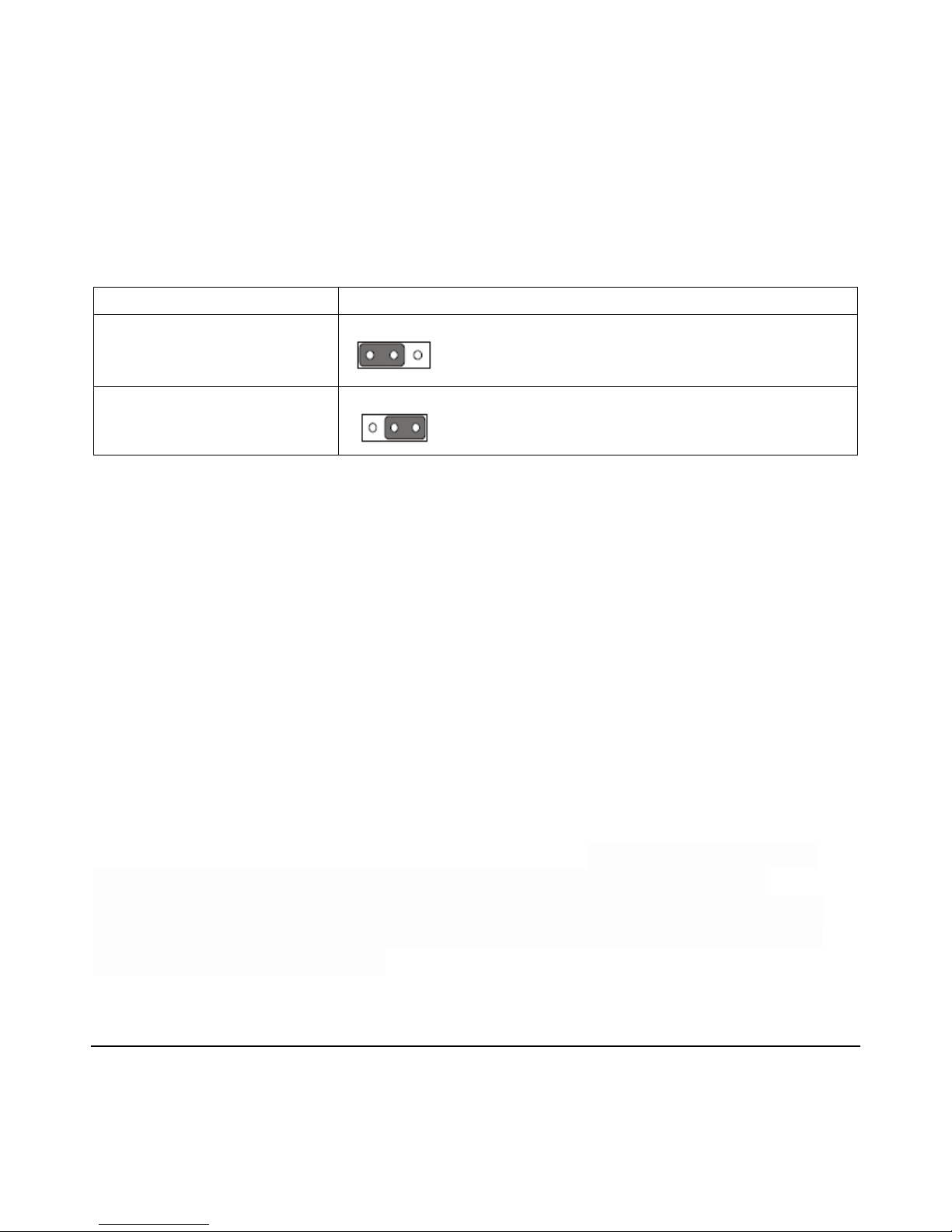
29.0 CMOS Clear (CMOS1)
The AIMB-285 motherboard contains a jumper that can erase CMOS data and reset
the system BIOS information. Normally this jumper should be set with pins 1-2
closed. If you want to reset the CMOS data, set J1 to 2-3 closed for just a few seconds,
and then move the jumper back to 1-2 closed. This procedure will reset the
CMOS to its default setting.
Function
Jumper Setting
*Keep CMOS data
1-2 closed
Clear CMOS data
2-3 closed
*Default
30.0 Installing Software and Drivers
Drivers and utilities are in the “Drivers” of the hard drive.
30.1 Operating Systems
Your All-in-One computer is designed to work with a wide variety of operating
systems including but not limited to Embedded OS, Windows XP, Windows Vista,
Windows 7, Windows 8 and Windows 10.
If you purchased the Windows operating system for your All-in-One computer, the
operating system and drivers have already been installed for you.
30.2 Video Driver
The MP5000i5v2 series use the Intel® HD Graphics 530. The HD Graphics 530 is an
integrated graphics solution by Intel, and based on the Skylake GT2 graphics
processor, the card supports DirectX 12.0. It features 192 shading units, 24 texture
mapping units and 3 ROPs. The GPU is operating at a frequency of 300 MHz, which
can be boosted up to 1050 MHz. HD Graphics 530 is connected to the rest of the
system using a PCIe 3.0 x1 interface.
Page 21

M I N T R O N I X C O M P U T E R S O L U T I O N S
124 Old Mill Road, Suite H
Greenville, SC 29607
855-672-6464
Page 21
Version 1-2018
30.3 Audio Driver
The MP5000i5v2 has a built-in audio controller. Windows driver can be installed by
running the program in the respective “audio” directory. For motherboards with the
optional HD Audio feature, we recommend that you connect a high-definition front
panel audio module to this connector to take advantage of the motherboard’s high
definition audio capability.
30.4 Network Driver
The MP5000i5v2 is equipped with two high-performance 1000 Mbps Ethernet LAN
adapter, which are supported by all major network operating systems. The RJ-45
jacks on the rear panel provides for convenient LAN connection. The MP5000i5v2 has
dual Gigabit Ethernet LANs via dedicated PCI Express x1 lanes Realtek 8111G (LAN1 &
LAN2) that offer bandwidth of up to 500 MB/sec, eliminating the bottleneck of
network data flows and incorporating Gigabit Ethernet at 1000 Mbps.
Realtek (LAN1 & LAN2) Gigabit integrated controllers support all major network
operating systems. However, the installation procedure varies from system to system.
Install the driver from the “Drivers” directory on your computer and decompressed
the file. Select the "Autorun" then navigate to the directory for your OS.
30.5 Touch Screen Driver
The MP5000I5V2 has an ELO serial touch controller. A universal driver is included in
the respective ELO touch directory.
30.6 Tuning the Touch Screen Under Windows
If you wish to calibrate the touch screen while under Windows, go to “Control Panel”
and select “Touch” icon. Choose “calibrate” to set the touch positions and click “OK”
to save the setup.
30.7 Other Applications
Please refer to the manuals accompanying your additional software or hardware.
Page 22
M I N T R O N I X C O M P U T E R S O L U T I O N S
124 Old Mill Road, Suite H
Greenville, SC 29607
855-672-6464
Page 22
Version 1-2018
31.0 Troubleshooting
If your system does not operate correctly at first, re-read the instructions regarding
the procedure being performed. If problems occur with third party software, consult
the accompanying documentation. Please check this section for possible solutions. If
the problem still cannot be resolved, contact your authorized dealer.
31.1 Initial Inspection
Oftentimes the simplest things can cause the most confusing errors. Always check the
following:
1. The power cord is securely connected to both the AC outlet and your Panel
Touch.
2. The Panel Touch is turned on.
31.2 Peripherals Configuration Problems
If one or more of your peripherals is not working correctly, it often can be the result of
an improper configuration either with the device driver or the BIOS. To check device
drivers, enter Windows and check the Control Panel for possible conflicts. Default IRQ
settings are included in appendices. Enter the BIOS program to verify the
configuration settings.
Page 23

M I N T R O N I X C O M P U T E R S O L U T I O N S
124 Old Mill Road, Suite H
Greenville, SC 29607
855-672-6464
Page 23
Version 1-2018
31.3 Connection Problems
If you are having problems with your peripherals and have checked the possible
solutions above, the connection between your Panel Touch and the peripheral may be
the problem. Verify the cable signal output.
32.0 Standard IRQ Settings
IRQ
Priority
Standard Functions
0
1
System Timer
1
2
Keyboard Controller
2
-
Redirect to IRQ#9
3
11
IRQ Holder for PCI Steering*
4
12
Communications Port (COM1)*
5
13
IRQ Holder for PCI Steering
6
14
Floppy Disk Controller
7
15
Printer Port (LPT)*
8
3
System CMOS/Rear Time
9
4
IRQ Holder for PCI Steering*
10
5
IRQ Holder for PCI Steering*
11
6
IRQ Holder for PCI Steering*
12
7
PS/2 Compatible Mouse Port*
13
8
Numeric Data Processor
14
9
Primary IDE Channel
15
10
Secondary IDE Channel
33.0 Optional Magnetic Stripe Reader
MSR213U is a HID Keyboard emulation device. It accepts keyboard input from
Windows applications.
Page 24

M I N T R O N I X C O M P U T E R S O L U T I O N S
124 Old Mill Road, Suite H
Greenville, SC 29607
855-672-6464
Page 24
Version 1-2018
33.1 Reader Test
The following process will test MSR213U installation:
1. Run the Notepad application from Start ? Programs ? Accessories ? Notepad
under Windows
2. Swipe any card through the reader MSR213U.
3. The card data should appear on the Notepad if the MSR213U installed properly.
33.2 Changing Configuration
The MSR configurations can be changed through software installed on the system.
They are factory preset and normally do not need to be changed by the user.
To enter the setting mode:
Connect keyboard to your MP5000i5v2 computer.
Run .MSR213U setting AP
Follow instructions on the screen to change settings
33.3 Optional 2x20 LCD Character Display
The 2x20 character display is an alpha numeric LCD with back light. It is driven by a
serial interface controller and normally set at COM4. The board receives control and
character codes which are then displayed on the LCD. This is a receive-only device.
33.4 Power-Up Initialization
Upon power-up, the controller goes into its initialization sequence. The board is
designed to initialize in two states:
1. physical power up
2. software power up.
After 250mS, the board is ready to receive software power up. YOU MUST SEND THE
BOARD A CLEAR SCREEN COMMAND (HEX 0C) TWO TIMES AT HALF SECOND
INTERVALS. This will initialize the controller completely. The LCD display is NOT hot
pluggable or hot swappable!
Page 25
M I N T R O N I X C O M P U T E R S O L U T I O N S
124 Old Mill Road, Suite H
Greenville, SC 29607
855-672-6464
Page 25
Version 1-2018
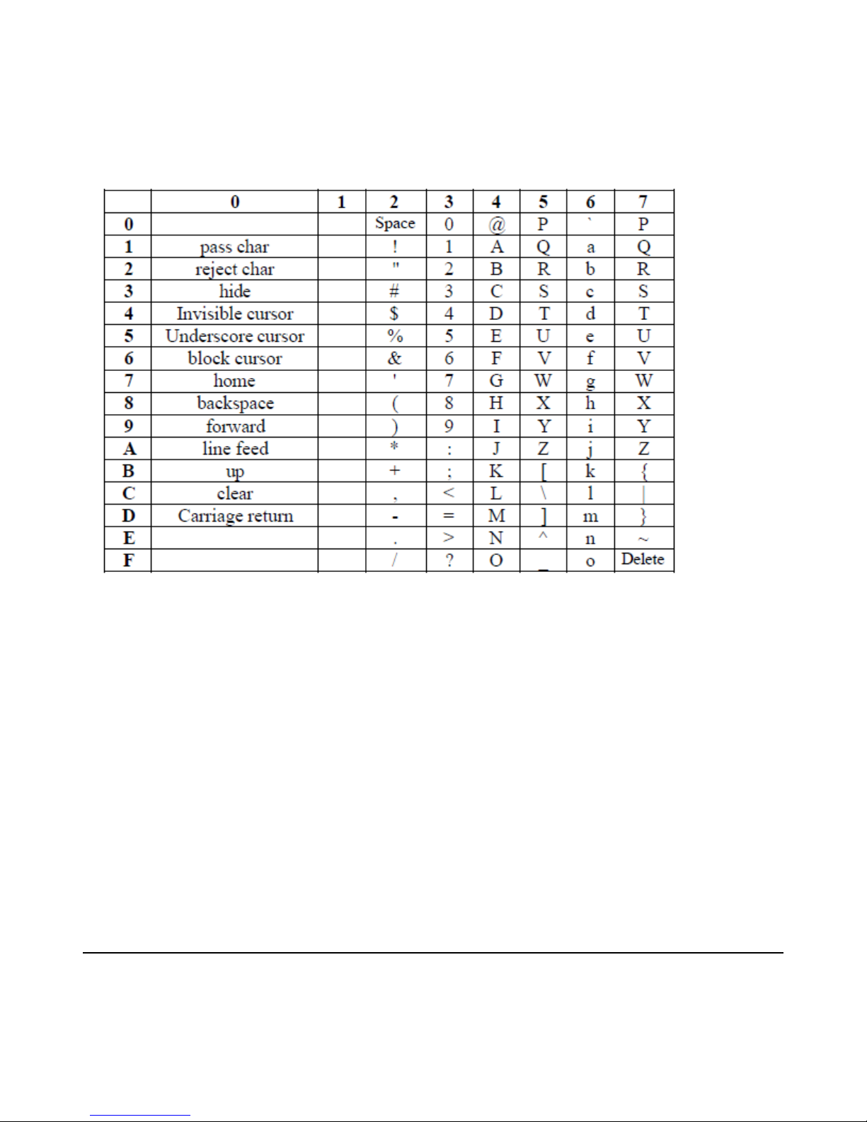
34.0 Communications Settings: 9600,N,8,1, COMx
34.1 Character Codes
 Loading...