

Page 1
Stratos
Family of Cardiac Resynchronization
Therapy Pacemakers
Technical Manual
Page 2
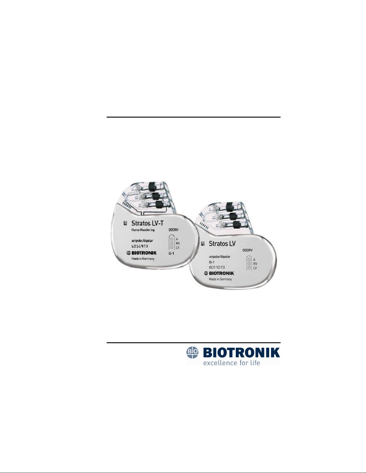
Stratos CRT-Ps
Implantable Cardiac Resynchronization Therapy Pacemakers
Stratos
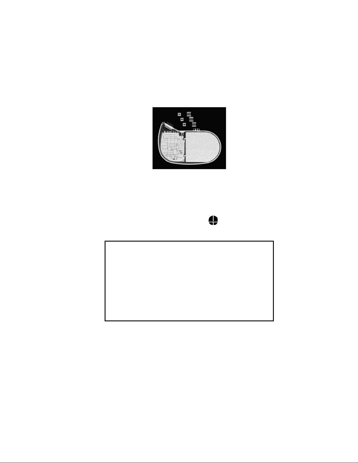
X-Ray identification
Radiopaque Identification
A radiopaque identification code is visible on standard x-ray, and
identifies the pulse generator:
Stratos LV/LV-T
SV
CAUTION
Lead / CRT-P Compatibility – Because of the numerous
available 3.2-mm configurations (e.g., the IS-1 and VS-1
standards), lead/ CRT-P compatibility should be confirmed
with the CRT-P and/or lead manufacturer prior to the
implantation of the system.
IS-1, wherever stated in this manual, refers to the
international standard, whereby leads and generators from
different manufacturers are assured a basic fit. [Reference
ISO 5841-3:1992(E)].
©2008 BIOTRONIK, Inc., all rights reserved.
Page 3

Stratos LV/LV-T Technical Manual i
Contents
1. General ..............................................................................1
1.1 Device Description ........................................................1
1.2 Indications .....................................................................2
1.3 Contraindications ..........................................................3
1.4 Note to Physician ..........................................................3
1.5 Warnings and Precautions ............................................3
1.5.1 Interactions with Other Medical Therapy...............4
1.5.2 Storage and Sterilization .......................................6
1.5.3 Lead Connection and Evaluation ..........................7
1.5.4 Programming and Operation.................................8
1.5.5 Home Monitoring ................................................. 11
1.5.6 Electromagnetic Interference (EMI) ....................13
1.5.7 Home and Occupational Environments...............13
1.5.8 Cellular Phones ................................................... 14
1.5.9 Hospital and Medical Environments....................15
1.5.10 Device Explant and Disposal............................... 15
1.6 Potential Effects of the Device on Health.................... 16
1.7 Clinical Studies............................................................17
1.7.1 Stratos LV Clinical Study – AVAIL CLS/CRT ......17
1.7.2 Stratos LV Clinical Study – OVID study ..............39
1.7.3 AVAIL and OVID Combined Primary
Endpoint-Complication-free Rate (Safety) ..........47
1.7.4 Tupos LV/ATx Clinical IDE Study -
OPTION CRT/ATx...............................................49
1.7.5 Conclusions Drawn from Studies ........................ 61
2. Programmable Parameters............................................63
2.1 Pacing Modes..............................................................63
2.1.1 Rate-adaptive Modes ..........................................63
2.1.2 DDD.....................................................................63
2.1.3 DDI ......................................................................67
2.1.4 DVI....................................................................... 67
2.1.5 VDD ..................................................................... 67
2.1.6 AAI and VVI .........................................................68
2.1.7 AAI, VVI ............................................................... 68
2.1.8 AOO, VOO...........................................................68
2.1.9 DOO ....................................................................68
2.1.10 VDI.......................................................................68
Page 4

ii Stratos LV/LV-T Technical Manual
2.1.11 OFF (ODO) ..........................................................69
2.2 Biventricular Synchronization of the Stratos CRT-Ps..69
2.3 Timing Functions .........................................................70
2.3.1 Basic Rate ...........................................................70
2.3.2 Rate Hysteresis ...................................................71
2.3.3 Scan Hysteresis...................................................72
2.3.4 Repetitive Hysteresis...........................................74
2.3.5 Night Mode ..........................................................75
2.3.6 Refractory Periods...............................................76
2.3.7 Atrial PMT Protection...........................................77
2.3.8 Ventricular Refractory Period ..............................78
2.3.9 AV Delay..............................................................78
2.3.10 VES Discrimination after Atrial Sensed Events ...80
2.3.11 Sense Compensation ..........................................80
2.3.12 Ventricular Blanking Period .................................81
2.3.13 Safety AV Delay ..................................................81
2.4 Pacing and Sensing Functions....................................82
2.4.1 Pulse Amplitude and Pulse Width .......................82
2.4.2 Sensitivity ............................................................83
2.4.3 Lead Polarity........................................................83
2.5 Automatic Lead Check ................................................84
2.6 Antitachycardia Functions: ..........................................86
2.6.1 Upper Rate and UTR Response .........................86
2.7 Wenckebach 2:1..........................................................86
2.8 Mode Switching ...........................................................88
2.9 PMT Management....................................................... 89
2.9.1 Protection ............................................................89
2.9.2 PMT Detection.....................................................90
2.10 Adjustment of the PMT Protection Window.................91
2.11 Atrial Upper Rate.........................................................92
2.12 Preventive Overdrive Pacing (Overdrive Mode) .........92
2.13 AES Detection and Pacing..........................................94
2.13.1 AES Detection .....................................................94
2.13.2 Post AES Stimulation ..........................................95
2.14 Parameters for Rate-Adaptive Pacing ........................95
2.14.1 Rate-Adaptation...................................................95
2.14.2 Sensor Gain.........................................................96
2.14.3 Automatic Sensor Gain .......................................96
2.14.4 Sensor Threshold ................................................97
2.14.5 Rate Increase ......................................................97
Page 5

Stratos LV/LV-T Technical Manual iii
2.14.6 Maximum Activity Rate ........................................ 98
2.14.7 Rate Decay ..........................................................98
2.15 Sensor Stimulation ......................................................98
2.16 Rate Fading................................................................. 99
2.17 Home Monitoring (Stratos LV-T)................................100
2.17.1 Transmission of Information ..............................102
2.17.2 Patient Device ...................................................103
2.17.3 Transmitting Data ..............................................103
2.17.4 Types of Report Transmissions ........................105
2.17.5 Description of Transmitted Data........................107
2.18 Statistics ....................................................................109
2.18.1 Timing ................................................................109
2.18.2 Arrhythmia .........................................................109
2.18.3 Sensor ...............................................................109
2.18.4 Sensing..............................................................109
2.18.5 Pacing................................................................109
2.18.6 General Statistical Information ..........................110
2.19 Interrogating and/or Starting Statistics ......................110
2.20 Timing Statistics ........................................................ 111
2.20.1 Event Counter.................................................... 111
2.20.2 Event Episodes.................................................. 111
2.20.3 Rate Trend.........................................................112
2.20.4 Atrial and Ventricular Rate Histogram ...............112
2.21 Arrhythmia Statistics.................................................. 113
2.21.1 Tachy Episode Trend ........................................113
2.21.2 AF Classification................................................113
2.21.3 AES Statistics ....................................................114
2.21.4 VES Statistics ....................................................115
2.22 Sensor Statistics........................................................ 116
2.22.1 Sensor Rate Histogram .....................................116
2.22.2 Activity Report ...................................................117
2.22.3 Sensor Optimization ..........................................117
2.23 Sensing Statistics ...................................................... 117
2.24 Pacing Statistics ........................................................ 118
3. Follow-up Procedures.................................................. 119
3.1 General Considerations ............................................119
4. Real-Time IEGM ............................................................121
4.1 IEGM Recordings......................................................121
Page 6

iv Stratos LV/LV-T Technical Manual
5. Battery, Pulse and Lead Data ......................................123
5.1 Threshold Test - Testing the Pacing Function ...........123
5.2 P/R Measurement - Testing the Sensing Function....124
5.3 Testing for Retrograde Conduction ...........................125
5.4 Non-Invasive Programmed Stimulation (NIPS).........125
5.4.1 Description.........................................................125
5.4.2 Burst Stimulation ...............................................126
5.4.3 Programmed Stimulation...................................126
5.4.4 Back up Pacing..................................................126
5.4.5 NIPS Safety Features........................................127
6. Other Functions/Features............................................129
6.1 Temporary Programming...........................................129
6.2 Patient Data Memory.................................................130
6.3 Safe Program Settings ..............................................130
6.4 Magnet Effect ............................................................131
6.5 Position Indicator.......................................................131
6.6 Pacing When Exposed to Interference .....................132
7. Product Storage and Handling....................................135
7.1 Sterilization and Storage ...........................................135
7.2 Opening the Sterile Container...................................136
7.3 Pulse Generator Orientation .....................................138
8. Lead Connection ..........................................................139
8.1 Lead Configuration....................................................139
8.2 Lead Connection .......................................................140
9. Elective Replacement Indication (ERI).......................145
10. Explantation ..................................................................149
11. Technical Data...............................................................151
11.1 Available Pacing Modes............................................151
11.2 Pulse- and Control Parameters................................. 151
11.3 Diagnostic Memory Functions...................................156
11.4 Home Monitoring (Stratos LV-T)................................156
11.5 Additional Functions..................................................157
11.6 Programmers.............................................................158
11.7 Default Programs ......................................................159
11.8 Materials in Contact with Human Tissue...................159
11.9 Electrical Data/Battery...............................................159
11.10 Mechanical Data ..................................................160
Page 7

Stratos LV/LV-T Technical Manual v
12. Order Information.........................................................161
Appendix A ..........................................................................163
Page 8

vi Stratos LV/LV-T Technical Manual Stratos LV/LV-T Technical Manual 1
Page 9

1. General
1.1 Device Description
The Stratos LV and Stratos LV-T CRT-Ps are rate adaptive
pacemakers designed to provide Cardiac Resynchronization
Therapy (CRT). The Stratos CRT-Ps provide all standard
bradycardia pacemaker therapy with the additional capabilities of
biventricular pacing for CRT. Biventricular pacing in the
Stratos CRT-Ps can be programmed to initially pace in either the
right or left ventricular chambers with separately programmable
outputs for both left and right channels. Sensing of cardiac
signals only occurs in the right ventricular chamber.
The Stratos CRT-Ps can also provide single and dual chamber
pacing in a variety of rate-adaptive and non-rate adaptive pacing
modes. Pacing capability is supported by an extensive
diagnostic set. For motion-based rate-adaptation, the
Stratos CRT-Ps are equipped with an internal accelerometer.
This sensor produces an electric signal during physical activity of
the patient. If a rate-adaptive (R) mode is programmed, then the
accelerometer sensor signal controls the stimulation rate.
The Stratos LV-T additionally also employs BIOTRONIK’s Home
Monitoring™ technology, which is an automatic, wireless, remote
monitoring system for management of patients with implantable
devices. With Home Monitoring, physicians can review data
about the patient’s cardiac status and CRT-P’s functionality
between regular follow-up visits, allowing the physician to
optimize the therapy process. Stratos CRT-Ps are also
designed to collect diagnostic data to aid the physician’s
assessment of a patient’s condition and the performance of the
implanted device.
The bipolar IS-1 connections are used for pacing and sensing
(right atrial and ventricle) and the additional IS-1 connection is
used for pacing in the left ventricle in either a bipolar or unipolar
configuration depending on the left ventricular lead. The pulse
amplitude and pulse width of each of the three channels is
separately programmable.
Page 10

2 Stratos LV/LV-T Technical Manual
Stratos CRT-Ps are designed to meet all indications for Cardiac
Resynchronization Therapy in CHF patients as well as those for
bradycardia therapy as exhibited in a wide variety of patients.
The Stratos family is comprised of two CRT-Ps that are designed
to handle a multitude of situations.
Stratos LV
Stratos LV-T
Throughout this manual, specific feature and function
descriptions may only be applicable to the Stratos LV-T and
those features will be referenced as such. Otherwise, reference
to Stratos CRT-Ps refers to both devices.
Triple chamber, rate-adaptive,
unipolar/bipolar pacing CRT-P
Triple chamber, rate-adaptive,
unipolar/bipolar pacing CRT-P with Home
Monitoring
1.2 Indications
The Stratos LV and Stratos LV-T Cardiac Resynchronization
Therapy Pacemakers (CRT-Ps) are indicated for patients who
have moderate to severe heart failure (NYHA Class III/IV),
including left ventricular dysfunction (EF ≤ 35%) and
QRS ≥ 120 ms and remain symptomatic despite stable, optimal
heart failure drug therapy.
Page 11

Stratos LV/LV-T Technical Manual 3
1.3 Contraindications
Use of Stratos LV and Stratos LV-T CRT-Ps are contraindicated
for the following patients:
• Unipolar pacing is contraindicated for patients with an
implanted cardioverter-defibrillator (ICD) because it may
cause unwanted delivery or inhibition of ICD therapy.
• Single chamber atrial pacing is contraindicated for
patients with impaired AV nodal conduction.
• Dual chamber and single chamber atrial pacing is
contraindicated for patients with chronic refractory atrial
tachyarrhythmias.
1.4 Note to Physician
As with any implantable pulse generator, there are certain
infrequent risks associated with Stratos CRT-Ps. Section 1.6
lists the adverse events that have been observed or may
potentially occur with these Cardiac Resynchronization Therapy
Pacemakers. The warnings and precautions listed in
Section 1.5 should be taken under serious consideration in order
to aid in avoiding device failures and harm to the patient.
Regular monitoring of the patient and their implanted device
should be conducted to identify performance concerns and
ensure appropriate therapy is being administered to the patient.
Please communicate any performance concerns to BIOTRONIK
and to FDA.
All explanted devices should be returned to the manufacturer for
testing to help understand device reliability and performance.
Refer to Section 10 for recommended procedures for handling
explanted devices.
1.5 Warnings and Precautions
Certain therapeutic and diagnostic procedures may cause
undetected damage to a Cardiac Resynchronization Therapy
Pacemakers, resulting in malfunction or failure at a later time.
Please note the following warnings and precautions:
Page 12

4 Stratos LV/LV-T Technical Manual
Magnetic Resonance Imaging (MRI) – Avoid use of magnetic
resonance imaging as it has been shown to cause movement of
the CRT-Ps within the subcutaneous pocket and may cause pain
and injury to the patient and damage to the CRT-P. If the
procedure must be used, constant monitoring is recommended,
including monitoring the peripheral pulse.
Rate Adaptive Pacing – Use rate adaptive pacing with care in
patients unable to tolerate increased pacing rates.
NIPS – Life threatening ventricular arrhythmias can be induced
by stimulation in the ventricle. Ensure that an external cardiac
defibrillator is accessible during tachycardia testing. Only
physicians trained and experienced in tachycardia induction and
reversion protocols should use non-invasive programmed
stimulation (NIPS).
High Output Settings – High output settings combined with
extremely low lead impedance may reduce the life expectancy of
the Stratos CRT-Ps. Programming of pulse amplitudes, higher
than 4.8 V, in combination with long pulse widths and/or high
pacing rates may lead to premature activation of the
replacement indicator.
1.5.1 Interactions with Other Medical Therapy
Before applying one of the following procedures, a detailed
analysis of the advantages and risks should be made. Cardiac
activity during one of these procedures should be confirmed by
continuous monitoring of peripheral pulse or blood pressure.
Following the procedures, CRT-P function and stimulation
threshold must be checked.
Therapeutic Diathermy Equipment – Use of therapeutic
diathermy equipment is to be avoided for pacemaker patients
due to possible heating effects of the CRT-P and at the implant
site. If diathermy therapy must be used, it should not be applied
in the immediate vicinity of the CRT-P or leads. The patient's
peripheral pulse should be monitored continuously during the
treatment.
Page 13

Stratos LV/LV-T Technical Manual 5
Transcutaneous Electrical Nerve Stimulation (TENS) –
Transcutaneous electrical nerve stimulation may interfere with
CRT-P function. If necessary, the following measures may
reduce the possibility of interference:
• Place the TENS electrodes as close to each other as
possible.
• Place the TENS electrodes as far from the CRT-P/lead
system as possible.
• Monitor cardiac activity during TENS use.
Defibrillation – The following precautions are recommended to
minimize the inherent risk of CRT-P operation being adversely
affected by defibrillation:
• The paddles should be placed anterior-posterior or along
a line perpendicular to the axis formed by the CRT-P
and the implanted lead.
• The energy setting should not be higher than required to
achieve defibrillation.
• The distance between the paddles and the CRT-P/leads
should not be less than 10 cm (4 inches).
Radiation – The CRT-P’s internal electronics may be damaged
by exposure to radiation during radiotherapy. To minimize this
risk when using such therapy, the CRT-P should be protected
with local radiation shielding.
Lithotripsy – Lithotripsy treatment should be avoided for CRT-P
patients since electrical and/or mechanical interference with the
CRT-P is possible. If this procedure must be used, the greatest
possible distance from the point of electrical and mechanical
strain should be chosen in order to minimize a potential
interference with the CRT-P.
Electrocautery – Electrocautery should never be performed
within 15 cm (6 inches) of an implanted CRT-P or leads because
of the danger of introducing fibrillatory currents into the heart
and/or damaging the CRT-P. Pacing should be asynchronous
and above the patient’s intrinsic rate to prevent inhibition by
interference signals generated by the cautery. When possible, a
bipolar electrocautery system should be used.
Page 14

6 Stratos LV/LV-T Technical Manual
For transurethral resection of the prostate, it is recommended
that the cautery ground plate be placed under the buttocks or
around the thigh, but not in the thoracic area where the current
pathway could pass through or near the CRT-P system.
1.5.2 Storage and Sterilization
Storage (temperature) – Recommended storage temperature
range is 5° to 55°C (41°-131°F). Exposure to temperatures
outside this range may result in CRT-P malfunction (see
Section 7.1).
Low Temperatures – Exposure to low temperatures (below
0°C) may cause a false elective replacement indication to be
present. If this occurs, warm the device to room temperature
and reset the ERI with magnet application (see Section 7.1).
Handling – Do not drop. If an unpackaged CRT-P is dropped
onto a hard surface, return it to BIOTRONIK (see Section 7.1).
FOR SINGLE USE ONLY - Do not re-sterilize the CRT-P or
accessories packaged with the CRT-P, they are intended for
one-time use.
Device Packaging – Do not use the device if the packaging is
wet, punctured, opened or damaged because the integrity of the
sterile packaging may be compromised. Return the device to
BIOTRONIK.
Storage (magnets) – Store the device in a clean area, away
from magnets, kits containing magnets, and sources of
electromagnetic interference (EMI) to avoid damage to the
device.
Temperature Stabilization – Allow the device to reach room
temperature before programming or implanting the device.
Temperature extremes may affect the initial device function.
Use Before Date – Do not implant the device after the USE
BEFORE DATE because the device may have reduced
longevity.
Page 15

Stratos LV/LV-T Technical Manual 7
1.5.3 Lead Connection and Evaluation
Lead Check –
Feature Description
: Lead Check is a feature that, when
activated, automatically measures the lead impedance with
every pace. Based on these measurements, the lead
configuration will be set to either unipolar or bipolar. Refer to
Section 2.5 for more details regarding this feature.
Caution
: Lead check will not lead to disabling of cardiac
resynchronization therapy. It limits the use of the
resynchronization features.
1. Lead check is possible only when the right ventricle is
paced first.
2. Lead check works only when the pacing voltages are
programmed between 2.4 and 4.8 V. The lead check
feature can be programmed OFF in patients that require
cardiac resynchronization therapy.
Care should be taken when programming Stratos CRT-Ps with
Lead Check ON as the device may switch from bipolar to
unipolar pacing and sensing without warning. This situation may
be inappropriate when using a Stratos CRT-P for patients with
an Implantable Cardioverter Defibrillator (ICD). The following
associated message appears when programming this feature:
“Lead check may result in a switch to unipolar pacing and
sensing, which may be inappropriate for patients with an
ICD.”
Additionally, Lead Check should be programmed OFF before
lead connection as the feature will automatically reprogram the
device to unipolar in the absence of a lead.
Lead / CRT-P Compatibility – Because of the numerous
available 3.2-mm configurations (e.g., the IS-1 and VS-1
standards), lead/ CRT-P compatibility should be confirmed with
the CRT-P and/or lead manufacturer prior to the implantation of
the system.
Page 16

8 Stratos LV/LV-T Technical Manual
IS-1, wherever stated in this manual, refers to the international
standard, whereby leads and generators from different
manufacturers are assured a basic fit. [Reference ISO 58413:1992(E)].
Lead Configuration – The polarity of the implanted lead
dictates what lead configuration can be programmed for the
CRT-P. Pacing will not occur with a unipolar lead if the lead
configuration of the respective channel is programmed to bipolar
(see Section 8).
Setscrew Adjustment – Back-off the setscrew(s) prior to
insertion of lead connector(s) as failure to do so may result in
damage to the lead(s), and/or difficulty connecting lead(s).
Cross Threading Setscrew(s) – To prevent cross threading
the setscrew(s), do not back the setscrew(s) completely out of
the threaded hole. Leave the torque wrench in the slot of the
setscrew(s) while the lead is inserted.
Tightening Setscrew(s) – Do not overtighten the setscrew(s).
Use only the BIOTRONIK supplied torque wrench.
Sealing System – Be sure to properly insert the torque
wrench into the perforation at an angle perpendicular to the
connector receptacle. Failure to do so may result in damage to
the plug and its self-sealing properties.
1.5.4 Programming and Operation
IEGM – Due to the compression processes that the signals
undergo, the IEGM recordings are not suitable for making some
specific cardiac diagnoses, such as ischemia; although, these
tracings may be useful in diagnosing arrhythmias, device
behavior or programming issues.
Post AES - Before activating post-AES, check whether the
selected program can cause Pacemaker Mediated Tachycardia
(PMT) and whether post-AES pacing results.
Overdrive Pacing Mode - When programming the overdrive
pacing mode, check whether the selected program can cause
PMT, and whether atrial over drive pacing would result.
Corresponding to the measured retrograde conduction time, the
PMT protection interval must be programmed to a correct value.
Page 17

Stratos LV/LV-T Technical Manual 9
AV Hysteresis – If the AV hysteresis is enabled along with the
algorithm for recognizing and terminating PMTs (PMT
management), the AV delay for recognizing and terminating a
PMT has a higher priority than the AV hysteresis.
Sensing – The Stratos CRT-Ps do not sense in the left ventricle.
AV Conduction – In patients with intact AV conduction, the
intrinsic atrial tachycardia is conducted to the ventricle 1:1. With
the resynchronization mode activated, spontaneous rate of the
right ventricle mode is synchronized for a rate up to 200 ppm in
the left ventricle. For this reason, biventricular pacing mode
should be turned OFF in such cases.
Unipolar/Bipolar – If the pacing or sensing function is to be
programmed to bipolar in the atrial channel, it must be verified
that bipolar leads have been implanted in that chamber. If the
atrial lead is unipolar, unipolar sensing and pacing functions
must be programmed in that chamber. Failure to program the
appropriate lead configuration could result in patient
experiencing entrance and/or exit block.
In addition, if the atrial lead polarity setting within the Patient
Data Memory has been set to bipolar, the polarity of the
corresponding implanted lead must be confirmed to be bipolar.
Safe Program – Activating the “Safe Program” is a way of
quickly programming the device to multiple settings in the event
of an emergency. These settings include unipolar pacing with
pacing output OFF in the left ventricular channel. Refer to
Section 6.3 for further details.
Programmers – Use only BIOTRONIK’s ICS 3000 programmer
equipped with appropriate software to program Stratos CRT-Ps.
Do not use programmers from other manufacturers.
Pulse Amplitude – Programming of pulse amplitudes, higher
than 4.8 V, in combination with long pulse widths and/or high
pacing rates can lead to premature activation of the replacement
indicator. If a pulse amplitude of 7.2 V or higher is programmed
and high pacing rates are reached, output amplitudes may differ
from programmed values.
Page 18

10 Stratos LV/LV-T Technical Manual
Pacing thresholds – When decreasing programmed output
(pulse amplitude and/or pulse width), the pacing threshold must
first be accurately assessed to provide a 2:1 safety margin.
EMI – Computerized systems are subject to (Electromagnetic
Interference (EMI) or “noise”. In the presence of such
interference, telemetry communication may be interrupted and
prevent programming of the Stratos CRT-P.
Programming Modifications – Extreme programming changes
should only be made after careful clinical assessment. Clinical
judgment should be used when programming permanent pacing
rates below 40 ppm or above 100 ppm.
Short Pacing Intervals – Use of short pacing intervals (high
pacing rates) with long atrial and/or ventricular refractory periods
may result in intermittent asynchronous pacing and, therefore,
may be contraindicated in some patients.
OFF Mode – The OFF mode can be transmitted as a temporary
program only to permit evaluation of the patient’s spontaneous
rhythm. (see Section 2.1.11)
Myopotential Sensing – The filter characteristics of
BIOTRONIK implantable devices have been optimized to sense
electrical potentials generated by cardiac activity and to reduce
the possibility of sensing skeletal myopotentials. However, the
risk of CRT-P’s operation being affected by myopotentials
cannot be eliminated, particularly in unipolar systems.
Myopotentials may resemble cardiac activity, resulting in
inhibition of pacing, triggering and/or emission of asynchronous
pacing pulses, depending on the pacing mode and the
interference pattern. Certain follow-up procedures, such as
monitoring CRT-P performance while the patient is doing
exercises involving the use of pectoral muscles, as well as Holter
monitoring, have been recommended to check for interference
caused by myopotentials. If sensing of myopotentials is
encountered, corrective actions may include selection of a
different pacing mode or sensitivity setting.
Muscle or Nerve Stimulation – Inappropriate muscle or nerve
stimulation may occur with unipolar pacing when using a noncoated Stratos CRT-P.
Page 19

Stratos LV/LV-T Technical Manual 11
Atrial Sensitivity – In dual chamber systems, the atrial
sensitivity of 0.1 mV should only be programmed in conjunction
with a bipolar lead configuration.
Programmed to Triggered Modes – When programmed to
triggered modes, pacing rates up to the programmed upper limit
may occur in the presence of either muscle or external
interference.
Triggered Modes – While the triggered modes (DDT, DVT,
DDTR/A, DDTR/V, DDI/T, VDT, VVT, and AAT) can be
programmed permanently, these modes are intended for use as
temporary programming for diagnostic purposes. In triggered
pacing modes, pacing pulses are emitted in response to sensed
signals, and therefore the pacing pulse can be used as an
indicator, or marker of sensed events for evaluating the sensing
function of the pulse generator using surface ECG. However,
real-time telemetry of marker channels and/or intracardiac
electrogram via the programmer and programming wand is
recommended over the use of a triggered pacing mode in the
clinical setting. A triggered pacing mode may be preferred in
situations where positioning the programming head over the
pulse generator would be impossible or impractical (i.e., during
exercise testing or extended Holter monitoring).
Another possible application of triggered modes is to ensure
pacing as a short term solution during a period of inhibition of
pacing by extracardiac interference, mechanical noise signals, or
other sensing abnormalities. Because triggered modes emit
pacing pulses in response to sensed events, this may result in
unnecessary pacing during the absolute refractory period of the
myocardium, inappropriate pacing in response to oversensing of
cardiac or extracardiac signals. The risks associated with
triggered pacing include excessive pacing, arrhythmias due to
the R-on-T phenomenon, and early battery depletion. Therefore,
it is important that the triggered modes are not used for long
term therapy, and that the CRT-P is always returned to a nontriggered permanent program.
1.5.5 Home Monitoring
Patient’s Ability - Use of the Home Monitoring system requires
the patient and/or caregiver to follow the system instructions and
cooperate fully when transmitting data.
Page 20

12 Stratos LV/LV-T Technical Manual
If the patient cannot understand or follow the instructions
because of physical or mental challenges, another adult who can
follow the instructions will be necessary for proper transmission.
Electromagnetic Interference (EMI) – Precautions for EMI
interference with the Stratos CRT-Ps are provided in
Section 1.5.6. Sources of EMI including cellular telephones,
electronic article surveillance systems, and others are discussed
therein.
Use in Cellular Phone Restricted Areas - The mobile patient
device (transmitter/receiver) should not be utilized in areas
where cellular phones are restricted or prohibited (i.e.,
commercial aircraft).
Event Triggered Report - A timely receipt of the event report
cannot be guaranteed. The receipt is also dependent on
whether the patient was physically situated in the required
coverage range of the patient device at the time the event
information was sent.
Patient-Activated Report - The magnet effect must be
programmed “synchronous” if the [Patient Report] function is
activated.
Not for Conclusive Diagnosis - Because not all information
available in the implant is being transmitted, the data transmitted
by Home Monitoring should be evaluated in conjunction with
other clinical indicators (i.e., in-office follow-up, patient
symptoms, etc.) in order to make a proper diagnosis.
Frequency of Office Follow-Ups When Using Home
Monitoring - The use of Home Monitoring does not replace
regular follow-up examinations. When using Home Monitoring,
the time period between follow-up visits may not be extended.
Page 21

Stratos LV/LV-T Technical Manual 13
1.5.6 Electromagnetic Interference (EMI)
The operation of any implanted device may be affected by
certain environmental sources generating signals that resemble
cardiac activity. This may result in inhibition of pacing and/or
triggering or in asynchronous pacing depending on the pacing
mode and the interference pattern. In some cases (i.e.,
diagnostic or therapeutic medical procedures), the interference
sources may couple sufficient energy into a pacing system to
damage the device and/or cardiac tissue adjacent to the leads.
BIOTRONIK CRT-Ps have been designed to significantly reduce
susceptibility to electromagnetic interference (EMI). However,
due to the variety and complexity of sources creating
interference, there is no absolute protection against EMI.
Generally, it is assumed that EMI produces only minor effects, if
any, in CRT-P patients. If the patient may be exposed to one of
the following environmental conditions, then the patient should
be given the appropriate warnings.
1.5.7 Home and Occupational Environments
The following equipment (and similar devices) may affect normal
CRT-P operation: electric arc welders, electric melting furnaces,
radio/television and radar transmitters, power-generating
facilities, high-voltage transmission lines, electrical ignition
systems (also of gasoline-powered devices) if protective hoods,
shrouds, etc., are removed, electrical tools, anti-theft devices at
retail stores and electrical appliances, if not in proper condition
or not correctly grounded and encased.
Patients should exercise reasonable caution in avoidance of
devices which generate a strong electric or magnetic field. If
EMI inhibits pacing or causes a reversion to asynchronous
pacing or pacing at magnet rate, moving away from the source
or turning it off should allow the CRT-P to return to its normal
mode of operation. Some potential EMI sources include:
High Voltage Power Transmission Lines – High voltage power
transmission lines may generate enough EMI to interfere with
CRT-P operation if approached too closely.
Page 22

14 Stratos LV/LV-T Technical Manual
Home Appliances – Home appliances normally do not affect
CRT-P operation if the appliances are in proper condition and
correctly grounded and encased. There are reports of CRT-P
disturbances caused by electrical tools and by electric razors
that have touched the skin directly over the CRT-P.
Communication Equipment – Communication equipment such
as microwave transmitters, linear power amplifiers, or highpower amateur transmitters may generate enough EMI to
interfere with CRT-P operation if approached too closely.
Commercial Electrical Equipment – Commercial electrical
equipment such as arc welders, induction furnaces, or
resistance welders may generate enough EMI to interfere with
CRT-P operation if approached too closely.
Electrical Appliances – Electric hand-tools and electric razors
(used over the skin directly above the CRT-P) have been
reported to cause pacemaker disturbances. Home appliances
that are in good working order and properly grounded do not
usually produce enough EMI to interfere with implanted device
operation.
Electronic Article Surveillance (EAS) – Equipment such as
retail theft prevention systems may interact with the CRT-Ps.
Patients should be advised to walk directly through and not to
remain near an EAS system longer than necessary.
Radio-Frequency Identification (RFID) – RFID tags may
interact with the CRT-Ps. Patients should be advised to avoid
leaving a device containing such a tag within close proximity to
the CRT-P (i.e., inside a shirt pocket).
1.5.8 Cellular Phones
Recent studies have indicated there may be a potential
interaction between cellular phones and pacemaker operation.
Potential effects may be due to either the radio frequency signal
or the magnet within the phone and could include inhibition or
asynchronous pacing when the phone is within close proximity
(within 6 inches [15 cm]) to the CRT-P.
Page 23

Stratos LV/LV-T Technical Manual 15
Based on testing to date, effects resulting from an interaction
between cellular phones and the implanted pacemakers have
been temporary. Simply moving the phone away from the
implanted device will return it to its previous state of operation.
Because of the great variety of cellular phones and the wide
variance in patient physiology, an absolute recommendation to
cover all patients cannot be made.
Patients having an implanted CRT-P who operate a cellular
phone should:
• Maintain a minimum separation of 6 inches (15 cm)
between a hand-held personal cellular phone and the
implanted device. Portable and mobile cellular phones
generally transmit at higher power levels compared to
hand held models. For phones transmitting above
3 watts, maintain a minimum separation of 12 inches
(30 cm) between the antenna and the implanted device.
• Patients should hold the phone to the ear opposite the
side of the implanted device. Patients should not carry
the phone in a breast pocket or on a belt over or within
6 inches (15 cm) of the implanted device as some
phones emit signals when they are turned ON but not in
use (i.e., in the listen or standby mode). Store the
phone in a location opposite the side of implant.
1.5.9 Hospital and Medical Environments
Refer to Section 1.5.1 for information regarding CRT-P
interaction with the following medical procedures / environments:
• Electrosurgical Cautery
• Lithotripsy
• External Defibrillation
• High Radiation Sources
1.5.10 Device Explant and Disposal
Device Incineration - Never incinerate a CRT-P. Be sure the
CRT-P is explanted before a patient who has died is cremated.
(see Section 10)
Explanted Devices – Return all explanted devices to
BIOTRONIK.
Page 24

16 Stratos LV/LV-T Technical Manual
1.6 Potential Effects of the Device on
Health
The following possible adverse events may occur with this type
of CRT-P based on implant experience including:
Potential Adverse Events
• Air embolism
• Allergic reactions to
contrast media
• Arrhythmias
• Bleeding
• Body rejection
phenomena
• Cardiac tamponade
• Chronic nerve damage
• Damage to heart valves
• Elevated pacing
thresholds
• Extrusion
• Fluid accumulation
• Infection
• Keloid formation
• Lead dislodgment
• Lead fracture / insulation
damage
• Lead-related
thrombosis
• Local tissue reaction /
fibrotic tissue formation
• Muscle or nerve
stimulation
• Myocardial damage
• Myopotential sensing
• Pacemaker mediated
tachycardia
• Pneumothorax
• Pocket erosion
• Hematoma
• Device migration
• Thromboembolism
• Undersensing of
intrinsic signals
• Venous occlusion
• Venous or cardiac
perforation
Page 25

Stratos LV/LV-T Technical Manual 17
1.7 Clinical Studies
The subsequent sections summarize the following three clinical
studies that were used to support the safety and effectiveness of
the Stratos LV/LV-T CRT-Ps.
• The AVAIL CLS/CRT clinical study
• The OVID clinical study (OUS)
• The OPTION CRT/ATx clinical study
Two of the studies, AVAIL CLS/CRT and OVID, collected
significant safety data supporting use of the Stratos LV/LV-T
CRT-P system. The third study, OPTION CRT/ATx, supports
the effectiveness of cardiac resynchronization therapy (CRT).
The OPTION CRT/ATx study was conducted on a device that
delivers CRT but, in addition, also offers defibrillation therapy
(CRT-D).
1.7.1 Stratos LV Clinical Study – AVAIL CLS/CRT
Study Design
The AVAIL CLS/CRT was a multi-center, prospective,
randomized, blinded clinical study designed to support approval
for cardiac resynchronization therapy for a Heart Failure (HF)
patient population not requiring back up defibrillation and that are
indicated for an ablate and pace procedures. All patients
enrolled into the clinical study were randomly assigned to one of
three groups using a 2:2:1 ratio for randomization.
Page 26

18 Stratos LV/LV-T Technical Manual
• Patients assigned to Group 1 received biventricular
pacing with CLS-based rate adaptive pacing using
BIOTRONIK’s Protos DR/CLS, which is a dual-chamber
pulse generator with CLS-based rate adaptive pacing.
During this study, the Protos DR/CLS devices were
implanted with two ventricular leads: the right ventricular
lead was connected to the ventricular port, and the left
ventricular lead was connected to the atrial port. Protos
DR/CLS was included in this study to evaluate
biventricular pacing with a different type of rate adaptive
sensor technology.
• Patients assigned to Group 2 received biventricular
pacing with accelerometer-based rate adaptive pacing
using the Stratos LV.
• Patients assigned to Group 3 (control group) received
right ventricular pacing with accelerometer-based rate
adaptive pacing using the Stratos LV. Therefore, 60% of
the patients received a Stratos LV device.
Primarily, the study evaluated and compared the functional
benefits of CRT between the three randomized groups using a
composite endpoint consisting of a six-minute walk test (meters
walked) and quality of life measurement (assessed using the
Minnesota Living with Heart Failure Questionnaire). Relevant
measurements were completed twice for each patient: once at
the Baseline evaluation (prior to implant and ablation) and again
at a six-month follow-up evaluation. The data collected during
this clinical study was used to demonstrate superiority of CRT to
RV only pacing. This study also evaluated the safety of both the
Protos DR/CLS and Stratos LV devices through an analysis of
the complication-free rate through six months. Secondarily, the
study also evaluated the superiority of CRT with CLS rate
adaptation compared to CRT with accelerometer rate adaptation.
Page 27

Stratos LV/LV-T Technical Manual 19
Clinical Inclusion Criteria
To support the objectives of this investigation, patients were
required to meet the following inclusion criteria prior to
enrollment:
• Meet the indications for therapy
• Persistent (documented for more than 7 days),
symptomatic AF with poorly controlled rapid ventricular
rates or permanent, (documented for more than 30 days
with failed cardioversion, or longstanding AF of 6 months
or more) symptomatic AF with poorly controlled rapid
ventricular rates.
• Eligible for AV nodal ablation and permanent pacemaker
implantation
• NYHA Class II or III heart failure
• Age ≥ 18 years
• Understand the nature of the procedure
• Ability to tolerate the surgical procedure required for
implantation
• Give informed consent
• Able to complete all testing required by the clinical
protocol
• Available for follow-up visits on a regular basis at the
investigational site
Page 28

20 Stratos LV/LV-T Technical Manual
Clinical Exclusion Criteria
To support the objectives of this investigation, the exclusion
criteria at the time of patient enrollment included the following:
• Meet one or more of the contraindications
• Have a life expectancy of less than six months
• Expected to receive heart transplantation within six
months
• Enrolled in another cardiovascular or pharmacological
clinical investigation
• Patients with an ICD, or being considered for an ICD
• Patients with previously implanted biventricular pacing
systems
• Patients with previously implanted single or dual
chamber pacing system with > 50% documented
ventricular pacing
• Patients with previous AV node ablation
• Six-minute walk test distance greater than 450 meters
• Any condition preventing the patient from being able to
perform required testing
• Presence of another life-threatening, underlying illness
separate from their cardiac disorder
• Conditions that prohibit placement of any of the lead
systems
Follow-Up Schedule
At the enrollment screening, the physician evaluated the patient
to verify that all inclusion/exclusion criteria have been met in
accordance to the protocol and the patient has signed the
informed consent. After successful enrollment, all patients were
implanted with either a Stratos LV CRT-P or Protos DR/CLS
device. Evaluations at the Four Week, Three and Six Month
follow-ups included NYHA classification, medications, and
percentage of ventricular pacing.
Page 29

Clinical Endpoints
Stratos LV/LV-T Technical Manual 21
Primary Endpoint: Complication-free Rate (Safety)
The safety of the Stratos LV was evaluated based on
complications (adverse events that require additional invasive
intervention to resolve) related to the implanted CRT system
which includes the Stratos LV, the right ventricular, the left
ventricular lead, lead ventricular lead adapters (if used) and the
implant procedure. The target complication-free rate at six
months is 85%.
Primary Endpoint: Six Minute Walk Test & QOL (Effectiveness)
The purpose of Primary Endpoint 1 was to evaluate the
effectiveness of the CRT (Groups 1 and 2) compared to RV only
(Group 3) pacing as measured by the average composite rate of
improvement in six minute walk test and QOL.
Accountability of PMA Cohorts
After randomization and enrollment, 23 patients (8 in Group 1, 8
in Group 2 and 7 in Group 3) did not receive an implant. The
reasons for patients not receiving an implant are outlined in
Figure 1
. Two additional patients in Group 1 had an
unsuccessful first implant attempt (unable to implant the LV
lead), but follow up data was not received.
Page 30

22 Stratos LV/LV-T Technical Manual
Enrolled and Randomized Patients
Group 1 43
Group 2 50
Group 3 25
Implant Attempted
Group 1 39
Group 2 44
Group 3 21
Successful implant
Group 1 33
Group 2 42
Group 3 18
Completed 6-Month Follow-up
Group 1 23
Group 2 30
Group 3 15
No im pla nt Atte mpte d
Withdrawal of Consent
Not Meeting Inclusion Criteria
Unsuccessful implant
Withdrawal of IC before 2nd Attempt
Follow-up to failed implant data pending
Ablation/Abla tion Data Pending
6-Month Fol low-up Da ta
Patient Death before 6-Month
Withdrew before 6-Month FU
Not Reached 6-Month FU or Data Pending
6-month FU Not Completed
Figure 1: Patient Accountability
Demographics and Baseline Parameters
Group 1 2
Group 2 4
Group 3 3
Group 1 2
Group 2 2
Group 3 1
Group 1 4
Group 2 2
Group 3 3
Group 1 2
Group 2 0
Group 3 0
Group 1 3
Group 2 0
Group 3 0
Group 1 0
Group 2 2
Group 3 0
Group 1 1
Group 2 1
Group 3 0
Group 1 6
Group 2 8
Group 3 3
Group 1 0
Group 2 1
Group 3 0
Table 1
provides a summary of the patient demographics at
enrollment. There were no statistical differences in enrollment
demographics between the 3 groups.
Page 31

Stratos LV/LV-T Technical Manual 23
Table 1: Patient Demographics at Enrollment
Characteristic Group1 Group 2 Group 3
Age @
Enrollment (Yrs)
Mean ± SE
Range
Gender
Male
Female
Six-Minute Walk
Distance
(meters)
Mean ± SE
Range
New York Heart
Association
Class
Class II
Class III
Underlying Heart
Disease
Dilated
Cardiomyopathy
Hypertrophic
Cardiomyopathy
Valvular Heart
Disease
Coronary Artery
Disease
Hypertension
No underlying
structural heart
disease
N=42
73.7 ± 1.3
56 to 90
N=42
18 (42.9%)
24 (57.1%)
N=42
262.7 ±
15.1
78 to 420
N=42
23 (54.8%)
19 (45.2%)
N=42
8 (19.0%)
4 (9.5%)
12 (28.6%)
19 (45.2%)
37 (88.1%)
3 (7.1%)
N=50
72.3 ± 1.2
51 to 86
N=50
19 (38.0%)
31 (62.0%)
N=50
283.6 ±
13.8
37 to 438
N=50
18 (36.0%)
32 (64.0%)
N=49
11 (22.4%)
1 (2.0%)
12 (24.5%)
28 (57.7%)
37 (75.5%)
2 (4.1%)
N=25
71.5 ± 1.6
52 to 85
N=25
13 (52.0%)
12 (48.0%)
N=25
267.8 ±
22.9
23 to 420
N=25
10 (40.0%)
15 (60.0%)
N=25
1 (4.0%)
2 (8.0%)
5 (20.0%)
6 (24.0%)
19 (76.0%)
7 (28.0%)
P-value
0.534*
0.553**
0.395*
0.189**
0.125**
0.216**
0.792**
0.031**
0.348**
0.007**
Page 32

24 Stratos LV/LV-T Technical Manual
Table 1: Patient Demographics at Enrollment
Characteristic Group1 Group 2 Group 3
Other Medical
History
Diabetes
Chronic Lung
Disease
Thyroid Disease
Chronic Kidney
Disease
Prior Ischemic
Stroke or TIA
Prior Embolic
Events
(non-
cerebrovascular)
*One-way ANOVA, ** Chi-Square test (2-sided)
N=29
13 (44.8%)
7 (24.1%)
12 (41.4%)
4 (13.8%)
7 (24.1%)
1 (2.3%)
N=36
9 (25.0%)
16 (44.4%)
12 (33.3%)
5 (13.9%)
10 (27.8%)
3 (6.0%)
N=17
4 (23.5%)
7 (41.2%)
5 (29.4%)
1 (5.9%)
6 (35.3%)
2 (8.0%)
P-value
0.287**
0.211**
0.791**
0.836**
0.726**
0.653**
Table 2 provides a summary of the AF medical history. Table 3
provides a summary of cardiac medications patients were taking
at the time of enrollment. Please note some categories may
equal more than 100% as several categories allow more than
one response. In some cases, complete demographic data was
not provided for all patients. There were no statistical
differences in AF medical history and cardiac medication at
enrollment between the 3 groups.
Page 33

Stratos LV/LV-T Technical Manual 25
Table 2: Atrial Fibrillation Demographics at Enrollment
Characteristic Group 1 Group 2 Group 3 P-value*
Classification of
Atrial Fibrillation
Persistent AF
Permanent AF
Classification of
Symptoms Related
to AF
Palpitations
Chest Pain
Dyspnea or shortness
of breath
Fatigue
Lightheadedness or
syncope
Other
Previous AF
Ablation
No
Yes
Past Medications
for Rate or Rhythm
Control
Amiodarone
Digoxin
Diltiazem
Disopyramide
Dofetilide
Flecanide
Ibutilide
Procainamide
Propafenone
Sotolol
Verapamil
Metoprolol
Propranolol
Other Beta-Blockers
Other Medications
N=42
10 (23.8%)
32 (76.2%)
N=42
32 (76.2%)
6 (14.3%)
36 (85.7%)
34 (81.0%)
17 (40.5%)
9 (21.4%)
N=42
37 (88.1%)
5 (11.9%)
N=41
12 (29.3%)
17 (41.5%)
17 (41.5%)
0 (0.0%)
4 (9.8%)
5 (12.2%)
0 (0.0%)
0 (0.0%)
2 (4.9%)
9 (22.0%)
5 (12.2%)
19 (46.3%)
0 (0.0%)
7 (17.1%)
5 (12.2%)
N=50
17 (34%)
33 (66%)
N=49
34 (69.4%)
7 (14.3%)
40 (81.6%)
45 (91.8%)
13 (26.5%)
11 (22.4%)
N=50
47 (94.0%)
3 (6.0%)
N=48
10 (20.8%)
22 (45.8%)
23 (47.9%)
3 (6.3%)
3 (6.3%)
5 (10.4%)
0 (0.0%)
2 (4.2%)
4 (8.3%)
10 (20.8%)
8 (16.7%)
28 (58.3%)
0 (0.0%)
15 (31.3%)
5 (10.4%)
N=24
6 (25%)
18 (75%)
N=25
14 (56.0%)
3 (12.0%)
19 (76.0%)
18 (72.0%)
9 (36.0%)
10 (40.0%)
N=25
21 (84.0%)
4 (16.0%)
N=24
10 (41.7%)
13 (54.2%)
12 (50.0%)
0 (0.0%)
2 (8.3%)
1 (4.2%)
1 (4.2%)
0 (0.0%)
0 (0.0%)
2 (8.3%)
3 (12.5%)
10(41.7%)
1 (4.2%)
4 (16.7%)
1 (4.2%)
0.537
0.236
1.000
0.568
0.149
0.329
0.205
0.354
0.192
0.683
0.804
0.228
0.895
0.656
0.215
0.506
0.423
0.389
0.829
0.382
0.215
0.248
0.656
Page 34

26 Stratos LV/LV-T Technical Manual
Table 2: Atrial Fibrillation Demographics at Enrollment
Characteristic Group 1 Group 2 Group 3 P-value*
Rate Control
Medication,
Reasons for
Discontinuation
Ineffective
Not tolerated
Other
Rhythm Control
Medication,
Reasons for
Discontinuation
Ineffective
Not tolerated
Other
Cardioversion
History
Successful prior
electrical
cardioversion
Transthoracic
Transvenous
Unsuccessful prior
electrical
cardioversion
Transthoracic
Transvenous
No electrical
cardioversion
attempted
Successful prior
pharmacological
cardioversion
Unsuccessful prior
pharmacological
cardioversion
No pharmacological
cardioversion
attempted
*Chi-Square test (2-sided)
N=17
10 (58.8%)
8 (47.1%)
1 (5.9%)
N=22
17 (77.3%)
6 (27.3%)
1 (4.5%)
N=42
13 (31.0%)
13 (100.0%)
0 (0.0%)
15 (35.7%)
15 (100.0%)
0 (0.0%)
17 (40.5%)
5 (11.9%)
8 (19.0%)
23 (54.8%)
N=20
13 (65.0%)
7 (35.0%)
2 (10.0%)
N=25
20 (80.0%)
7 (28.0%)
1 (4.0%)
N=49
16 (32.7%)
15 (93.8%)
1 (6.3%)
14 (28.6%)
14 (93.3%)
2 (13.3%)
20 (40.8%)
3 (6.1%)
11 (22.4%)
29 (59.2%)
N=12
9 (75.0%)
3 (25.0%)
0 (0.0%)
N=13
8 (61.5%)
6 (46.2%)
2 (15.4%)
N=25
10 (40.0%)
10 (100.0%)
0 (0.0%)
7 (28.0%)
7 (100.0%)
0 (0.0%)
9 (36.0%)
3 (12.0%)
7 (28.0%)
15 (60.0%)
0.558
0.760
0.800
0.759
0.530
0.430
0.760
0.808
0.680
0.741
0.936
0.547
0.678
0.915
Page 35

Stratos LV/LV-T Technical Manual 27
Table 3: Current Cardiac Medications at Enrollment
Drug Category
Anti-Arrhythmics 12 (28.6%) 10 (20.4%) 4 (16.0%)
Rate Control Medications 32 (76.2%) 43 (87.8%) 20(80.0%)
Anti-thrombic Agents 17 (40.5%) 19(38.8%) 11 (44.0%)
Anti-Coagulants 36 (85.7%) 40 (81.6%) 22 (88.0%)
ACE Inhibitors 16 (38.1%) 16 (32.7%) 8 (32.0%)
Angiotensin-Receptor
Blockers
Diuretics 30 (71.4%) 34 (69.4%) 13 (52.0%)
Inotropes 1 (2.4%) 2 (4.1%) 0 (0.0%)
Nitrates 3 (7.1%) 6 (12.2%) 2 (8.0%)
Beta-Blockers for CHF 6 (14.3%) 9 (18.4%) 4 (16.0%)
Other 23 (54.8%) 26 (53.1%) 14 (56.0%)
*Chi-Square test (2-sided)
Group 1
N=42
10 (23.8%) 7 (14.3%) 4 (16.0%) 0.491
Group 2
N=50
Group 3
N=25
P-
value*
0.480
0.462
0.863
0.686
0.848
0.255
0.803
0.714
0.947
0.941
Safety and Effectiveness Results
A total of 118 patients were enrolled in the AVAIL CLS/CRT
clinical study at 20 sites:
There were 43 Group 1, 50 Group 2, and 25 Group 3 patients in
this prospective, multi-center, randomized clinical study. For
Group 1, there were 33 successful implants (76.7%) of the
Protos DR/CLS system. For Groups 2 and 3, there were 44 and
21 successful implants (88.0% and 84.0%) respectively of the
Stratos LV CRT-P system.
Page 36

28 Stratos LV/LV-T Technical Manual
• The study was designed to enroll 265 patients.
However, the study was terminated early due to slow
patient enrollment. There were no safety issues involved
in the termination decision. Due to the lack of patient
data, the AVAIL CLS/CRT study alone was insufficient to
support CRT pacing effectiveness or an ablate and pace
indication.
• The cumulative enrollment duration was 416.7 months
with a mean duration of 9.7 months for Group 1, 522.4
months with a mean duration of 10.4 months for
Group 2, and 261.1 months with a mean duration of
10.4 months for Group 3. 73 (61.9%) of the study
patients had enrollment durations greater than 6 months.
• There were 158 adverse events (115 observations in
68 patients and 43 complications in 34 patients). There
were no unanticipated adverse device effects reported.
• The overall protocol violation non-compliance rate is
0.4% in Group 1, 0.5% in Group 2, and 0.4% in Group 3.
The overall follow-up compliance rate is 99.8% in all
groups.
• There were 3 patient deaths reported, two in Group 2
and one in Group 3. The clinical investigators and
clinical events committee determined that none of these
deaths were related to the study devices.
• Both the CRT pacing and the RV pacing only groups
showed improvements in the primary composite
endpoint of quality of life and six-minute walk distance
between the baseline evaluation and the six-month
follow-up. In addition, there was a trend towards
improvement between the combined CRT pacing groups
compared to the RV pacing only group at six months.
Page 37

Stratos LV/LV-T Technical Manual 29
Primary Endpoint—Complication-free Rate (Safety)
The safety of the Stratos LV was evaluated based on
complications (adverse events that require additional invasive
intervention to resolve) related to the implanted CRT system
which includes the Stratos LV, the right ventricular, the left
ventricular lead, lead ventricular lead adapters (if used) and the
implant procedure. The target complication-free rate at six
months is 85%.
13 complications in these categories were seen in 11 patients
with cumulative enrollment duration of 783.5 months
(64.4 patient-years). 14.7% of the patients had a reported
complication in these categories. The rate of complications per
patient-year is 0.20. Details of the Stratos LV complications in
the AVAIL CLS/CRT study are listed in Table 4
.
Page 38

30 Stratos LV/LV-T Technical Manual
Table 4: AVAIL CLS/CRT Complication-Free Rate at
6 months – Stratos LV
Category
Number
of
Patients
% of
Patients
Number of
Complications
Complications
per patient-
year
Device-Related
Pocket
Infection/Pain
1
1.3%
2 0.03
Total 1 1.3% 2 0.03
LV Lead Related
High Threshold
No Capture
Diaphragmatic
Stimulation
1
1
Dislodgement 2
1.3%
1.3%
2.7%
1 0.02
1 0.02
2 0.03
Total 4 5.3% 4 0.06
RV Lead Related
High Threshold
/ No Capture
4 5.3% 4 0.06
Total 4 5.3% 4 0.06
Procedure
Pneumothorax 1
User error 1
1.3%
1.3%
1 0.02
1 0.02
Hematoma 1 1.3% 1 0.02
Total 3 4.0% 3 0.05
Total Lead
and
Procedure
11 14.7% 13 0.20
Related
Page 39

Stratos LV/LV-T Technical Manual 31
Table 4: AVAIL CLS/CRT Complication-Free Rate at
6 months – Stratos LV
Category
Number
of
Patients
% of
Patients
Number of
Complications
Complications
per patient-
year
Other Medical
Worsening
CHF
Repeat
Ablation
2 2.7% 2 0.03
3 4.0% 3 0.05
Non-CHF
cardiac
3 4.0% 3 0.05
symptoms
Other Medical
3 4.0% 3 0.05
Total 10 13.3% 11 0.17
Total—All
Patients and
19 25.3% 24 0.37
Categories
Number of Patients = 75 Number of Patient-Years = 64.4
The freedom from Stratos LV system-related and procedurerelated complications was 85.33%, with a one sided lower 95%
confidence bound of 76.89%. Therefore, the procedure, lead and
device related complication-free rate at 6 months met the prespecified acceptance criterion of equivalence (non-inferiority)
within 10% of 85% (p = 0.0196).
Observed Adverse Events
Adverse events are classified as either observations or
complications. Observations are defined as clinical events that
do not require additional invasive intervention to resolve.
Complications are defined as clinical events that require
additional invasive intervention to resolve.
Of the 104 adverse events reported in the Stratos LV study
groups, there have been 76 observations in 45 patients and 28
complications in 20 patients with a cumulative enrollment
duration of 64.4 patient-years. 26.7% of the enrolled Stratos LV
patients have experienced a complication. The rate of
complications per patient-year is 0.43. 60.0% of the enrolled
study patients have a reported observation. The rate of
observations per patient-year is 1.18.
Page 40

32 Stratos LV/LV-T Technical Manual
Complications and observations for the Stratos LV study groups
are summarized in Table 5
patients may not equal the sum of the number of patients listed
in each category, as an individual patient may have experienced
more than one complication or observation.
and Table 6. The total number of
Page 41

Stratos LV/LV-T Technical Manual 33
Table 5: Summary of Complications – Stratos LV
Category
Number
of
Patients
% of
Patients
Number of
Complications
Complications
per patient-
year
Device-Related
Pocket
Infection or
2
2.7%
3 0.05
Pain
Total
2
2.7%
3 0.05
LV Lead-Related
High
Threshold /
1 1.3% 1 0.02
No Capture
Diaphragmatic
Stimulation
1 1.3% 1 0.02
Dislodgement 2 2.7% 2 0.03
Total
4 5.3% 4 0.06
RV Lead Related
High
Threshold /
4 5.3% 4 0.06
No Capture
Total
4 5.3% 4 0.06
Procedure
Pneumothorax 1 1.3% 1 0.02
User error 1 1.3% 1
Hematoma 1 1.3% 1
Total
3 4.0% 3 0.05
0.02
0.02
Total Lead
and
Procedure
11 14.7% 14 0.22
Related
Other Medical
Worsening
CHF
2 2.7% 2 0.03
Non-CHF
cardiac
5 6.7% 5 0.08
symptoms
Page 42

34 Stratos LV/LV-T Technical Manual
Table 5: Summary of Complications – Stratos LV
Category
Repeated
ablation
Number
of
Patients
% of
Patients
Number of
Complications
3 4.0% 3 0.05
Complications
per patient-
year
Lead addition 1 1.3% 1 0.02
Other medical 3 4.0% 3 0.05
Total
12 16.0% 14 0.22
Total—All
Patients and
20 26.7% 28 0.43
Categories
Number of Patients = 75, Number of Patient-Years = 64.4
Table 6: Summary of Observations – Stratos LV
Category
High Threshold
/ No Capture
Diaphragmatic
Stimulation
Total
Number
of
Patients
1
13
% of
Patients
LV Lead-Related
Number of
Complications
1.3%
17.3%
1 0.02
13 0.20
14 18.7% 14 0.22
Observations
per patient-
year
Device Related
Pocket Infection
or pain
Total
5 6.7% 5 0.08
5 6.7% 5 0.08
Procedure
Pneumothorax 1 1.3% 1 0.02
Atrial edema 1 1.3% 1 0.02
User error 1 1.3% 1 0.02
Total
3 4.0% 3 0.05
Total Lead,
Device and
Procedure
19 25.3% 22 0.34
Related
Page 43

Stratos LV/LV-T Technical Manual 35
Table 6: Summary of Observations – Stratos LV
Category
Number
of
Patients
% of
Patients
Number of
Complications
Observations
per patient-
year
Other Medical
Dizziness 3 4.0% 3 0.05
Other Medical 24 32.0% 34 0.53
Worsening CHF 8 10.7% 8 0.12
Ventricular
arrhythmias
Shortness of
Breath
2 2.7% 2 0.03
5 6.7% 5 0.08
Stroke / TIA 1 1.3% 1 0.02
Non-CHF
cardiac
1 1.3% 1 0.02
symptoms
Total
35 46.7% 54 0.84
Total—All
Patients and
45 60.0% 76 1.18
Categories
Number of Patients = 75 Number of Patient-Years = 64.4
There have been 3 patient deaths reported for the Stratos LV
groups (out of 75 Stratos LV patients). None of the deaths were
related to the implanted CRT-P system. Table 7
provides a
summary of reported patient deaths.
Table 7: Summary of Patient Deaths
Stratos LV Patients
(N = 75)
Sudden Cardiac 1
Non-Cardiac 2
All Causes
3
Page 44

36 Stratos LV/LV-T Technical Manual
Primary Endpoint: Six Minute Walk Test & QOL
(Effectiveness)
The purpose of Primary Endpoint 1 was to evaluate the
effectiveness of the CRT (Groups 1 and 2) compared to RV only
(Group 3) pacing as measured by the average composite rate of
improvement in six minute walk test and QOL.
• Stratos LV Effectiveness (Group 2 compared to
Group 3): The average composite rate for Group 2
(N=30) was 48.1% with a standard error of 12.3%. The
average composite rate for Group 3 (N=15) was 33.0%
with a standard error of 12.3%. The difference in the
mean composite rate between Group 2 and Group 3 is
15.1%. The p value for superiority is 0.442.
• Protos DR/CLS Effectiveness (Group 1 compared to
Group 3): The average composite rate for the Group 1
(N=23) is 36.8% with a standard error of 7.9%. The
average composite rate for Group 3 (N=15) is 33.0%
with a standard error of 12.3%. The difference in the
mean composite rate between Group 1 and Group 3 is
3.8%. The p value for superiority is 0.788.
Table 8
presents the average composite rate of improvement in
six minute walk test distance and QOL score, the average 6minute walk test distance and the average QOL score at
Baseline and at the Six-Month follow-up, as well as the average
difference in 6-minute walk test distance and QOL score
between Baseline and the Six-Month follow-up for the CRT
(Groups 1 and 2) and RV only (Group 3) for those patients with
six minute walk test data and complete QOL data at both
Baseline and the Six-Month follow-up.
Page 45

Stratos LV/LV-T Technical Manual 37
Table 8: Composite of Six Minute Walk Test and QOL
(Effectiveness)
RV only
Group 3
(N = 15)
Mean ± SE
25.7% ±
15.0%
(student’s
2-sided)
Category
Distance Walked
at Baseline
Distance Walked
at Six-Months
∆ Distance
Walked (meters)
∆ Distance
Walked (%)
QOL Score at
Baseline
QOL Score at
Six-Months
CRT (Group 1 & 2)
(N = 53)
Mean ± SE
262.8 ± 13.7 288.5 ± 22.4 0.369
312.8 ± 14.6 345.8 ± 30.0 0.303
50.0 ± 12.2 57.2 ± 26.7 0.790
39.0% ± 13.1%
58.5 ± 2.9 49.3 ± 5.5 0.137
30.1 ± 3.2 27.7 ± 6.5 0.731
p value
t-test,
*
*
*
*
0.610
*
*
0.537
0.525
*
*
*
∆ in QOL Score
∆ in QOL Score
(%)
28.4 ± 3.4 21.6 ± 7.7 0.367
47.4% ± 5.1%
Composite Rate 43.2% ± 7.7%
40.4% ±
11.1%
33.0% ±
12.3%
*
p value is provided for informational purposes to show trends only; clinical
significance is not indicated by p values for analyses that were not prespecified.
Page 46

38 Stratos LV/LV-T Technical Manual
Primary Effectiveness Endpoint Analysis and Conclusions
The primary effectiveness endpoint evaluated CRT effectiveness
(Groups 1 and 2) compared to RV only effectiveness (Group 3),
as measured by the composite rate of the six minute walk test
and QOL improvement from Baseline to the Six-Month follow-up
(Table 8
). For this analysis, both six minute walk test and QOL
were equally weighted at 50%. Due to the small number of
patients with data available for the analysis of the primary
endpoint, the results lack power to demonstrate that biventricular
pacing with either the Protos DR/CLS or Stratos LV device is
statistically different from RV only pacing with the Stratos LV
device in patients undergoing an “ablate and pace” procedure.
Multi-site Poolability and Gender Analysis
The AVAIL CLS/CRT clinical report included data from multiple
centers with centralized coordination, data processing, and
reporting at BIOTRONIK. All of the clinical centers followed the
requirements of an identical clinical protocol, and all of the
clinical centers used the same methods to collect and report the
clinical data, including New York Heart Association evaluation,
six-minute walk test, Minnesota Living with Heart Failure
questionnaire, and echocardiographic measurements. In order
to justify pooling of the data from multiple centers, several
analyses were completed. All of the centers were divided into
two groups (Small and Large sites) based on implant volume.
Comparisons were then made between the patient populations
based on the results of the safety and effectiveness endpoints.
Additionally, analyses were performed on the data collected in
the AVAIL clinical investigation in order to compare results
between males and females. The first type of analysis
compared enrollment by patient gender in each of the study
groups. The second type of analysis compared effectiveness
and safety outcomes in each gender.
The results of these analyses demonstrated poolability of the
data between sites. There were no significant differences in the
primary safety or effectiveness endpoints between high and low
volume implant centers.
Page 47

Stratos LV/LV-T Technical Manual 39
The gender distribution in this clinical investigation was
consistent within the study groups and included a representative
proportion of enrolled female participants (57.2% versus 42.7%
male). There were no significant differences in the primary
safety or effectiveness endpoints between the male and female
population.
1.7.2 Stratos LV Clinical Study – OVID study
The OVID clinical study collected significant safety data
supporting the Stratos LV/LV-T CRT-P system.
Study Design
BIOTRONIK conducted the Corox Over-the-Wire Lead
Evaluation (OVID) prospective registry outside the United States
(OUS) of the Corox OTW Steroid LV lead in a multi-center trial
with legally marketed CRT-D and CRT-P pulse generators that
provide biventricular pacing therapy. Data from this registry is
presented in the following sections to support the safety of the
Stratos LV CRT-P.
The multi-center investigation was designed to validate the
safety of the Corox OTW Steroid LV lead through a comparison
of successfully implanted LV leads against a pre-defined
success rate threshold, when no anatomical restrictions prevent
access to the coronary sinus. The evaluation of safety is based
on the analysis of the incidence of adverse events, defined as
any complications or observations judged by the investigator to
be in probable relationship with Corox OTW Steroid LV lead
system. Additionally, the effectiveness of the leads was
evaluated using lead parameter data, including sensing
amplitudes, pacing thresholds, and impedance values.
In the OVID study, enrolled patients could be implanted with any
legally marketed CRT-P or CRT-D device. There were 121
patients enrolled in the OVID clinical study, and 89 patients were
implanted with a Stratos LV device.
Page 48

40 Stratos LV/LV-T Technical Manual
Clinical Inclusion Criteria
To support the objectives of this investigation, patients were
required to meet the following inclusion criteria prior to
enrollment:
• Meet the indications for bi-ventricular pacing
• Age ≥ 18 years
• Receiving optimal drug therapy for Congestive Heart
Failure treatment
• Give informed consent
Clinical Exclusion Criteria
To support the objectives of this investigation, the exclusion
criteria at the time of patient enrollment included the following
requirements:
• Myocardial infarction or unstable angina pectoris
• Acute myocarditis
• Life expectancy ≤ 6 months
• Planned cardiac surgical procedures or interventional
measures within the next 6 months
• Pregnancy
Follow-Up Schedule
All patients were implanted with the Corox OTW/Steroid LV lead
system and a CRT-P or CRT-D pulse generator capable of
providing bi-ventricular pacing for the treatment of CHF. The
specific study procedures were performed at:
• Pre-operative Visit
• Implantation
• Pre-discharge follow-up
• One-month follow-up
• Three-month follow-up
• Six-month follow-up
• Twelve-month follow-up
Page 49

Stratos LV/LV-T Technical Manual 41
Clinical Endpoints
The safety of the Stratos LV was evaluated based on
complications (adverse events that require additional invasive
intervention to resolve) related to the implanted CRT system
which includes the Stratos LV device, the atrial lead, the right
ventricular lead the left ventricular lead and the implant
procedure. The target complication-free rate at six months was
85%.
Accountability of PMA Cohorts
During the OVID study, 84 patients were implanted with the
Stratos LV CRT-P and Corox OTW/Steroid LV lead system.
Additionally, 5 other patients were implanted with a Stratos LV
CRT-P device following an unsuccessful Corox OTW/Steroid LV
lead implant attempt. Of these 5 patients, three were not
implanted with any LV pacing lead, one was implanted with a
non-study LV pacing lead and one was implanted with a
BIOTRONIK Elox P 60 BP placed in the RV outflow tract for
bi-focal ventricular pacing. These 5 patients were excluded from
the OVID study at 1 month post-implant, because the primary
endpoint of the OVID study was the evaluation of the safety and
effectiveness of the Corox OTW/Steroid lead.
Demographics and Baseline Parameters
Table 9
provides a summary of the patient demographics and
medical history for the 89 enrolled patients implanted with a
Stratos LV. The typical patient implanted with a Stratos LV
CRT-P was a 68 year old male with NYHA Class III heart failure,
Left Bundle Branch Block (LBBB), a mean QRS duration of
160 ms, and non-ischemic cardiomyopathy.
Page 50

42 Stratos LV/LV-T Technical Manual
Table 9: Patient Demographics
Characteristic Results
Age at Implant (Years) n=88
Mean ± SD 68 ± 10
Range 34 to 84
Gender n=89
Male 66 (74%)
Female 23 (26%)
QRS-width (ms) n=70
Mean ± SD 160 ± 23
Range 110 to 210
Etiology of Heart Failure n=87
Ischemic 32 (37%)
Non-Ischemic 55 (63%)
New York Heart Association (NYHA)
Classification
n=87
Class III 73 (84%)
Class IV 14 (16%)
Atrial Tachyarrhythmias N=87
None 48 (55%)
Atrial flutter 5 (5.7%)
Paroxysmal atrial fibrillation 19 (22%)
Persistent atrial fibrillation
10
(11.5%)
Other 5 (5.7%)
Ventricular Tachyarrhythmias N=87
None 80 (92%)
Ventricular fibrillation Sustained or non-sustained VT 5 (5.7%)
Other VT 2 (2.3%)
Existing/chronic leads prior to Corox
OTW/Steroid
1)
2)
n=88
None 73 (83%)
Yes, due to previous pacemaker therapy 15 (17%)
1)
non-sustained VT (n=4); no further information available (n=1); 2) VES (n=2)
Page 51

Stratos LV/LV-T Technical Manual 43
Safety and Effectiveness Results
• The cumulative implant duration was 760 months with a
mean duration of 9.2 months. Sixty-five (77%) of the
patients had implant durations greater than 6 months.
• The implant success rate for the Stratos LV CRT-P was
100% (89 out of 89). The implant success of the
Stratos LV CRT-P in combination with the
Corox OTW/Steroid LV lead was 94.4% (84 out of 89).
• The mean LV pacing threshold at implant was 0.9 and at
6-months was 0.9 volts.
• The mean R-wave at implant was 15.7 mV.
• The mean LV lead impedance at implant was 729 ohms
and at 6-months was 603 ohms.
• There were 29 adverse events (18 observations in
17 patients and 11 complications in 10 patients). There
were no unanticipated adverse device effects reported.
• There were 10 patient deaths reported in the OVID
study. The clinical investigators have determined that
no deaths were related to the Stratos LV CRT-P system.
• The overall follow-up compliance rate for the OVID study
is 93%.
Primary Endpoint—Complication-free Rate (Safety)
The safety of the Stratos LV was evaluated based on
complications (adverse events that require additional invasive
intervention to resolve) related to the implanted CRT system
which includes the Stratos LV device, the atrial lead, the right
ventricular lead, the left ventricular lead and the implant
procedure. The target complication-free rate at six months was
85%.
Ten (10) complications in these categories were seen in
10 patients with cumulative implant duration of 760 months
(63.3 patient-years). 11.2% of the patients had a reported
complication in these categories. The rate of complications per
patient-year was 0.16. Details of the Stratos LV complications in
the OVID study are listed in Table 10
.
Page 52

44 Stratos LV/LV-T Technical Manual
The freedom from Stratos LV system-related and procedurerelated complications was 88.76% with a one sided lower 95%
confidence bound of 81.69%. Therefore, the null hypothesis was
rejected, and it was concluded that the complication-free rate at
6 months is equivalent to 85% within 10% (p = 0.0014).
Observed Adverse Events
Adverse events are classified as either observations or
complications. Observations are defined as clinical events that
do not require additional invasive intervention to resolve.
Complications are defined as clinical events that require
additional invasive intervention to resolve.
Of the 29 adverse events reported, there were 18 observations
and 11 complications in a total of 89 patients. Table 10
Table 11
provide a summary by category of each type of
and
adverse event (complications and observations).
Table 10: Summary of Complications at 6 months
Category
Loss of
capture
Phrenic nerve
stimulation
Total
Number
of
Patients
Corox OTW/Steroid Lead-Related
% of
Patients
Number of
Complications
2 2.2% 2 0.03
1 1.1% 1 0.02
3 3.3% 3 0.05
Complications
per patient-
year
Atrial Lead Related
Loss of
capture
Total
1 1.1% 1 0.02
1 1.1% 1 0.02
RV Lead Related
Loss of
capture
3 3.3% 3 0.05
Elevated
Pacing
2 2.2% 2 0.03
thresholds
Total
5 5.6% 5 0.08
Page 53

Stratos LV/LV-T Technical Manual 45
Table 10: Summary of Complications at 6 months
Category
Number
of
Patients
% of
Patients
Number of
Complications
Complications
per patient-
year
Device Related
Pocket
infection
Total
Total System
Related
1 1.1% 1 0.02
1 1.1% 1 0.02
10 11.2% 10 0.16
Other Medical
Arrhythmias 1 1.1% 1 0.02
Total
1 1.1% 1 0.02
Overall
Complication
10 11.2% 11 0.17
Totals
Number of Patients = 89; Number of Patient-Years = 63.3
Table 11: Summary of Observations at 6 months
Observations
per patient-
year
Category
Number of
Patients
% of
Patients
Number of
Observations
Corox OTW/Steroid Lead-Related
Implant failure 5 5.6% 5 0.08
Phrenic nerve
stimulation
Total
4 4.5% 4 0.06
9 10.1% 9 0.14
Atrial Lead Related
Loss of
capture
Total
1 1.1% 1 0.02
1 1.1% 1 0.02
RV Lead Related
Elevated
Pacing
2 2.2% 2 0.03
thresholds
Total
2 2.2% 2 0.03
Page 54

46 Stratos LV/LV-T Technical Manual
Table 11: Summary of Observations at 6 months
Observations
per patient-
year
Category
Number of
Patients
% of
Patients
Number of
Observations
Device Related
Pocket
infection/
Pericardial
1 1.1% 1 0.02
Effusion
Total
Total System
Related
1 1.1% 1 0.02
12 13.5% 13 0.21
Medical
Arrhythmias 2 2.2% 2 0.03
Shortness of
breath,
1 1.1% 1 0.02
palpitations
Total
3 3.3% 3 0.05
Miscellaneous
Malfunction of
hemostatic
1 1.1% 1 0.02
valve
Improper
Lead
1 1.1% 1 0.02
preparation
Total
2 2.2% 2 0.04
Overall
Observation
17 19.1% 18 0.28
Totals
Number of Patients = 89; Number of Patient-Years = 63.3
There were a total of 10 patient deaths reported in the OVID
study for patients with the Stratos LV device. The clinical
investigators determined that no deaths were related to the
Stratos LV device system.
Page 55

Stratos LV/LV-T Technical Manual 47
1.7.3 AVAIL and OVID Combined Primary
Endpoint-Complication-free Rate (Safety)
The results from for the AVAIL CLS/CRT and OVID studies were
pooled to evaluate the safety of the Stratos LV device. The
safety of the Stratos LV was evaluated based on complications
(adverse events that require additional invasive intervention to
resolve) related to the implanted CRT system which includes the
Stratos LV, the atrial lead, the right ventricular lead, the left
ventricular lead and the implant procedure. The target
complication-free rate at six months was 85%.
Twenty-three (23) complications in these categories were seen
in 21 patients with cumulative implant duration of 127.7 years.
12.8% of the patients had a reported complication in these
categories. The rate of complications per patient-year was 0.18.
Details of the Stratos LV complications in the AVAIL CLS/CRT
and OVID studies are listed in Table 12
Table 12: OVID and AVAIL Complication-Free
Rate - Stratos LV
Category
Number
of
Patients
% of
Patients
LV Lead-Related
High
Threshold / No
3
1.8%
Capture
Diaphragmatic
Stimulation
2
Dislodgement 1
1.2%
1.2%
Total 7 4.3% 7 0.06
RV Lead Related
High
Threshold / No
9 5.5% 9 0.07
Capture
Total 9 5.5% 9 0.07
Atrial Lead Related
No Capture
1 0.6% 1 0.01
Total 1 0.6% 1 0.01
.
Number of
Complications
Complications
per patient-
year
3 0.02
2 0.02
2 0.01
Page 56

48 Stratos LV/LV-T Technical Manual
Table 12: OVID and AVAIL Complication-Free
Rate - Stratos LV
Category
Number
of
Patients
% of
Patients
Number of
Complications
Complications
per patient-
year
Device Related
Pocket
Infection
2 1.2% 3 0.02
Total 2 1.2% 3 0.02
Procedure
Pneumothorax 1 0.6% 1 0.01
User error 1 0.6% 1
Hematoma 1 0.6% 1
0.01
0.01
Total 3 1.8% 3 0.02
Total Lead,
Device and
Procedure
21 12.8% 23 0.18
Related
Other Medical
Arrhythmias
Repeated
ablation
Worsening
CHF
Other Medical
1 0.6% 1 0.01
3 1.8% 3 0.02
2 1.2% 2 0.02
3 1.8% 3 0.02
Non-CHF
cardiac
3 1.8% 3 0.02
symptoms
Total 11 6.7% 12 0.09
Total—All
Patients and
29 17.7% 35 0.27
Categtories
Number of Patients = 164 Number of Patient-Years = 127.7
Page 57

Stratos LV/LV-T Technical Manual 49
The freedom from Stratos LV system-related and procedurerelated complications was 87.2% with a one sided lower 95%
confidence bound of 82.09%. Therefore, the null hypothesis was
rejected, and it was concluded that the complication-free rate at
6 months is equivalent to 85% within 10% and the primary safety
endpoint was met (p = 0.0002)
*
.
1.7.4 Tupos LV/ATx Clinical IDE Study OPTION CRT/ATx
The CRT functionality of the Stratos CRT-P devices is based on
the FDA approved Tupos LV/ATx. Therefore, the data from the
OPTION CRT/ATx study supports the effectiveness of CRT.
The OPTION CRT/ATx study was conducted on the Tupos
LV/ATx, a device that delivers CRT but, in addition, also offers
defibrillation therapy (CRT-D).
Study Design
The purpose of the prospective, randomized, multi-center
OPTION CRT/ATx study was to demonstrate the safety and
effectiveness of the investigational Tupos LV/ATx Cardiac
Resynchronization Therapy Defibrillator (CRT-D) in patients with
congestive heart failure (CHF) and atrial tachyarrhythmias.
Patients in the study group were implanted with a BIOTRONIK
Tupos LV/ATx. Patients in the control group were implanted with
any legally marketed CRT-D. Patients in both the study and
control groups were implanted with a legally marketed left
ventricular lead.
*
p value is provided for informational purposes to show trends only; clinical
significance is not indicated by p values for analyses that were not prespecified.
Page 58

50 Stratos LV/LV-T Technical Manual
Primarily, the study evaluates and compares the functional
benefits of CRT between the two randomized groups using a
composite endpoint consisting of a six-minute walk test (meters
walked) and quality of life measurement (assessed using the
Minnesota Living with Heart Failure Questionnaire). Relevant
measurements were completed twice for each patient: once at
the Baseline evaluation (two-week post implant follow-up) and
again at a six-month follow-up evaluation. The data collected
during this clinical study was used to demonstrate equivalent
treatment of CHF in both the study and control groups. This
study also evaluated other outcomes including: the percentage
of time CRT is delivered, and other measures of CHF status,
including NYHA classification, peak oxygen consumption during
metabolic exercise testing, and the rate of hospitalization for
CHF.
Clinical Inclusion Criteria
To support the objectives of this investigation, patients were
required to meet the following inclusion criteria prior to
enrollment:
• Stable, symptomatic CHF status
• NYHA Class III or IV congestive heart failure
• Left ventricular ejection fraction ≤ 35% (measured within
six-months prior to enrollment)
• Intraventricular conduction delay (QRS duration greater
than or equal to 130 ms)
• For patients with an existing ICD, optimal and stable
CHF drug regimen including ACE-inhibitors and betablockers unless contraindicated (stable is defined as
changes in dosages less than 50% during the last
30 days)
• Indicated for ICD therapy
• History or significant risk of atrial tachyarrhythmias
• Willing to receive possibly uncomfortable atrial shock
therapy for the treatment of atrial tachyarrhythmias
• Able to understand the nature of the study and give
informed consent
Page 59

Stratos LV/LV-T Technical Manual 51
• Ability to tolerate the surgical procedure required for
implantation
• Ability to complete all required testing including the sixminute walk test and cardiopulmonary exercise testing
• Available for follow-up visits on a regular basis at the
investigational site
• Age greater than or equal to 18 years
Clinical Exclusion Criteria
To support the objectives of this investigation, the exclusion
criteria at the time of patient enrollment included the following:
• Previously implanted CRT device
• ACC/AHA/NASPE indication for bradycardia pacing
(sinus node dysfunction)
• Six-minute walk test distance greater than 450 meters
• Chronic atrial tachyarrhythmias refractory to
cardioversion shock therapy
• Receiving intermittent, unstable intravenous inotropic
drug therapy (patients on stable doses of positive
inotropic outpatient therapy for at least one-month are
permitted)
• Enrolled in another cardiovascular or pharmacological
clinical investigation
• Expected to receive a heart transplant within 6 months
• Life expectancy less than 6 months
• Presence of another life-threatening, underlying illness
separate from their cardiac disorder
• Acute myocardial infarction, unstable angina or cardiac
revascularization within the last 30 days prior to
enrollment
• Conditions that prohibit placement of any of the lead
systems
Page 60

52 Stratos LV/LV-T Technical Manual
Follow-Up Schedule
After successful enrollment, all patients were randomly assigned
to either the study group or the control group. The specific
procedures of this study were:
• Pre-enrollment screening
• Randomization
• System implantation
• Pre-discharge follow-up
• Baseline evaluation / CRT activation
• One-Month follow-up
• Three-Month follow-up
• Six-Month follow-up
• Subsequent routine follow-ups (every three months)
Clinical Endpoints
Primary Endpoint 1: Six Minute Walk Test & QOL (Effectiveness)
The purpose of Primary Endpoint 1 is to evaluate the
effectiveness of the Tupos LV/ATx system in providing CRT as
measured by the average composite rate of improvement in six
minute walk test and QOL.
Secondary Endpoint Results
1. The purpose of this secondary endpoint is to evaluate
improvement in functional capacity as measured by the six
minute walk test. The six minute walk test is a well-accepted
measure of functional capacity and exercise tolerance. Also,
this test more closely mimics the patient’s day-to-day
activities than maximal exercise testing.
2. The purpose of this secondary endpoint is to evaluate the
improvement in the patient’s NYHA classification.
Accountability of PMA Cohorts
After randomization and enrollment, 7 patients (4 in the study
group and 3 in the control group) did not receive an implant. The
reasons for patients not receiving an implant are outlined in
Figure 2
.
Page 61

Stratos LV/LV-T Technical Manual 53
Enrolled and Randomized
Patients
Study 133
Control 67
No implant Attempted
Withdrawal of Consent
Study 2
Control 1
Not Meeting Inclusion Criteria
Study 1
Control 1
Implant Attempted
Study 130
Control 65
Unsuccessful implant
Withdrawal of IC before 2nd Attempt
Expired before Second Attempt
Successful implant
Study 129
Control 64
6-Month Follow-up Data
Patient Death before 6-Month
Withdrawal before 6-Month
Not Reached 6-Month FU
Patients completed 6-Month
Follow-up
Study 100
Control 49
Figure 2: Patient Accountability
Demographics and Baseline Parameters
Study 1
Control 0
Study 0
Control 1
Study 7
Control 3
Study 1
Control 2
or Data Pending
Study 21
Control 10
Table 13
provides a summary of the pre-enrollment
demographics of enrolled patients.
Page 62

54 Stratos LV/LV-T Technical Manual
Table 13: Patient Demographics at Pre-Enrollment
Characteristic
Age at Enrollment (Years)
Mean ± SE
Range
Gender
Male
Female
Underlying Heart Disease
Ischemic Cardiomyopathy
Nonischemic Cardiomyopathy
Type of Bundle Branch Block
Left Bundle Branch Block
Right Bundle Branch Block
Other
New York Heart Association
Class
Class III
Class IV
Intrinsic QRS Duration (ms)
Mean ± SE
Range
Left Ventricular Ejection
Fraction (%)
Mean ± SE
Range
Six Minute Walk Distance
(meters)
Mean ± SE
Range
Quality of Life Questionnaire
Score
Mean ± SE
Range
*Student's t-test (2-sided) for means, **Fisher's Exact Test (2-sided) for 2
possible answers, ***Chi-Square test (2-sided) for more than 2 possible answers
Study
N=133
69.5 ± 0.9
43 to 88
93 (69.9%)
40 (30.1%)
100 (75.2%)
34 (25.6%)
91 (68.4%)
26 (19.5%)
19 (14.3%)
121 (91.0%)
12 (9.0%)
161.9 ± 2.0
130 to 252
22.1 ± 0.6
5 to 35
254.8 ± 8.9
20 to 451
54.3 ± 2.1
0 to 105
Control
N=67
69.1 ± 1.2
38 to 84
51 (76.1%)
16 (23.9%)
54 (80.6%)
15 (22.4%)
49 (73.1%)
10 (14.9%)
11 (16.4%)
60 (89.6%)
7 (10.4%)
156.1 ± 2.3
130 to 200
23.3 ± 0.8
10 to 35
250.5 ±
11.9
27 to 447
52.5 ± 3.1
0 to 102
P-
value
0.781*
0.407**
0.294***
0.877***
0.800**
0.073*
0.255*
0.775*
0.638*
Page 63

Stratos LV/LV-T Technical Manual 55
Table 14 provides a summary of cardiac medications patients
were taking at the time of enrollment. Some categories may be
more than 100% as several categories allow more than one
response.
Table 14: Cardiac Medications at Pre-Enrollment
Drug
Category
Specific CHF Medications
ACE inhibitors
Angiotensin receptor blockers
Beta blockers
Cardiac glycosides (Digoxin)
Diuretic
Inotropes
Anti-arrhythmics
Nitrates
*Student's t-test (2-sided) for means, **Fisher's Exact Test (2-sided) for 2
possible answers, ***Chi-Square test (2-sided) for more than 2 possible answers
Study
(N=133)
89 (66.9%)
21 (15.8%)
111 (83.5%)
60 (45.1%)
114 (85.7%)
1 (0.8%)
34 (25.6%)
36 (27.1%)
Control
(N=67) P-value
45 (67.2%)
16 (23.9%)
55 (82.1%)
35 (52.2%)
57 (85.1%)
3 (4.5%)
19 (28.4%)
14 (20.9%)
1.000**
0.180**
0.843**
0.370**
1.000**
0.110**
0.735**
0.390**
Safety and Effectiveness Results
A total of 200 patients were enrolled in the OPTION CRT/ATx
clinical study at 25 sites:
There were 133 study patients and 67 active control patients in
this prospective, multi-center, randomized clinical study. For the
study group, there were 129 successful implants (91.4%) of the
Tupos LV/ATx CRT-D system. For the active control group,
there were 64 successful implants (92.2%) of the legally
marketed CRT-D systems.
Page 64

56 Stratos LV/LV-T Technical Manual
• There were 192 endocardial and 19 epicardial leads
implanted in 193 patients. Investigators were allowed to
choose among any legally marketed LV lead according
to their familiarity with the lead and patient anatomy. The
Tupos LV/ATx CRT-D was implanted with 7 endocardial
and 4 epicardial lead models from 6 different
manufacturers. There were no adverse events reported
attributable to lead-generator incompatibility.
• The cumulative implant duration is 1240.4 months with a
mean duration of 9.6 months for the study group. The
cumulative implant duration is 596.5 months with a
mean duration of 9.3 months for the control group.
• The overall protocol compliance rate is 79.2% in the
study group and 85.9% in the control group. The overall
follow-up compliance rate is 99.4% in the study group
and 98.3% in the control group.
• There have been 10 patient deaths reported in the study
group and 4 patient deaths reported in the control group.
The clinical investigators have determined that no
deaths were related to the study device.
Primary Endpoint 1: Six Minute Walk Test & QOL
(Effectiveness)
The purpose of Primary Endpoint 1 is to evaluate the
effectiveness of the Tupos LV/ATx system in providing CRT as
measured by the average composite rate of improvement in six
minute walk test and QOL.
Table 15
presents the average composite rate of improvement in
six minute walk test distance and QOL score, the average 6minute walk test distance and the average QOL score at
Baseline and at the Six-Month follow-up, as well as the average
difference in 6-minute walk test distance and QOL score
between Baseline and the Six-Month follow-up for the Study and
Control Groups for those patients with six minute walk test data
and complete QOL data at both Baseline and the Six-Month
follow-up.
Page 65

Stratos LV/LV-T Technical Manual 57
Table 15: Composite of Six Minute Walk Test and QOL
(Effectiveness)
Category
Study Group
(N = 74)
Mean ± SE
Control Group
(N = 38)
Mean ± SE
Distance
Walked at
310.51 ± 10.89 288.76 ± 15.37 0.249
Baseline
Distance
Walked at
340.77 ± 12.32 301.84 ± 17.02 0.067
Six-Months
∆ Distance
Walked
QOL Score at
Baseline
QOL Score at
Six-Months
∆ in QOL
Score†
Composite
Rate
‡
30.26 ± 10.40
17.27% ± 5.59%
44.39 ± 2.78 45.53 ± 4.13 0.817
28.68 ± 2.66 33.95 ± 4.35 0.279
15.72± 2.83
19.08% ± 12.21%
18.18% ± 7.07% -2.36% ± 17.73% 0.030
13.08 ± 13.05
8.71% ± 5.26%
11.58 ± 3.45
-13.42% ±
34.54%
P-value
0.322
0.326
0.376
0.281
*
*
The calculated p-values are associated with a Student's t-test (2-sided) of the
equality of means in the two groups, except for the p-value of the composite rate,
which is associated with a test of equivalence (non-inferiority).
†
∆ in QOL Score is calculated as the average of the individual differences
between Baseline and Six-Months for each patient. Negative values for mean ∆
QOL in percent are possible when positive mean values for absolute changes in
QOL are recorded. In some cases, small, negative changes in absolute QOL
scores resulted in relatively large percentage changes.
‡
The Composite Rate (=(∆ Distance Walked (%) + ∆ QOL Score (%)) / 2) is
calculated for each patient and then averaged to obtain the Composite Rates.
For all calculations, a positive number represents improvement from Baseline to
Six-Months.
Page 66

58 Stratos LV/LV-T Technical Manual
Primary Effectiveness Endpoint Analysis and Conclusions
A composite rate of six minute walk test and QOL improvement
from Baseline to the Six-Month follow-up is evaluated as a
measure of CRT effectiveness. For this analysis both six minute
walk test and QOL are equally weighted at 50%.
The mean difference in the composite rate between study and
control group was 20.53% with an associated one-sided, 95%
confidence bound of (-6.10%). The p-value for non-inferiority
within 10% is 0.030. The analysis of the composite rate in six
minute walk test distance and QOL score demonstrates that the
study group is non-inferior to the control group and that the
primary effectiveness endpoint was met (p=0.030).
Secondary Endpoint Results
1. The purpose of this secondary endpoint is to evaluate
improvement in functional capacity as measured by the six
minute walk test. The six minute walk test is a well-accepted
measure of functional capacity and exercise tolerance. Also,
this test more closely mimics the patient’s day-to-day
activities than maximal exercise testing.
Table 16
summarizes the six minute walk test distance at
Baseline and the Six-Month follow-up for patients in the
study group and the control group.
Table 16: Six Minute Walk Distance
Distance
(meters)
Baseline
N
Mean ± SE
Range
Median
Six-Month
N
Mean ± SE
Range
Median
* Student's t-test, 2-sided
Study Control
127
283.14 ± 9.27
269.43 ± 13.77
23 to 511
302.00
93
329.73 ± 10.82
310.70 ± 15.49
78 to 596
335.00
61
29 to 507
244.00
44
91 to 489
313.00
Page 67

Stratos LV/LV-T Technical Manual 59
There are no clinically relevant differences in the six minute walk
test results between the study and the control group.
2. The purpose of this secondary endpoint is to evaluate the
improvement in the patient’s NYHA classification. Table 17
summarizes the average improvement in NYHA from
Baseline to Six-Months for 140 patients that were able to
complete both NYHA classification evaluations.
Table 17: Improvement in NYHA Classification at
Six-Months from Baseline
Change in
NYHA class
Number of
Improved 2
classes
Improved 1
class
Total
improved
No change 39
Worsened 1
class
Study
(N=97)
Patients
10
47
57
1
% of Total
Patients
Number of
10.3% 2 4.7%
48.5% 20 46.5%
58.8% 23 51.2%
40.2% 20 46.5%
1.0% 1 2.3%
Control
Patients
(N=43)
% of
Total
Patients
The study and the control group have similar NYHA classes and
similar rates of improvement in NYHA class from Baseline to the
Six-Month follow-up.
Page 68

60 Stratos LV/LV-T Technical Manual
Multi-site Poolability and Gender Analysis
The OPTION CRT/ATx clinical report includes data from multiple
centers with centralized coordination, data processing, and
reporting at BIOTRONIK. All of the clinical centers followed the
requirements of an identical clinical protocol, and all of the
clinical centers used the same methods to collect and report the
clinical data. In order to justify pooling of the data from multiple
centers, several analyses were completed. All of the centers
were divided into two groups based on implant volume.
Comparisons were then made between the patient populations
based on the results of each of the endpoints. Additionally,
analyses were performed on the data collected in the
OPTION CRT/ATx clinical investigation in order to compare
results between males and females. The first type of analysis
compared enrollment by patient gender in each of the study and
control groups. The second type of analysis compared
effectiveness outcomes in each gender.
The results of these analyses demonstrate poolability of the data
between sites. There were no significant differences in the
second primary endpoint or any of the secondary endpoints
between high and low volume implant centers.
The gender distribution in this clinical investigation is consistent
within the study groups and includes a representative proportion
of enrolled female participants (28.0% versus 72.0% male).
There were no significant differences in any of the primary or
secondary endpoints between the male and female population.
Page 69

Stratos LV/LV-T Technical Manual 61
1.7.5 Conclusions Drawn from Studies
The clinical study results support the safety and effectiveness of
the Stratos LV CRT-P device.
• The OPTION CRT/ATx clinical study completed and
reviewed under P050023 provided a reasonable
assurance that bi-ventricular pacing is effective in NYHA
class III/IV heart failure patients with a prolonged QRS
and a left ventricular ejection fraction <35%. The
addition of ICD back-up therapy does not affect the
biventricular pacing performance of the device.
• The AVAIL CLS/CRT and Corox (OVID) clinical studies
demonstrated the safety of the Stratos LV CRT-P in
NYHA class III/IV heart failure patients with a prolonged
QRS and a left ventricular ejection fraction
<35%.(OVID).
Page 70

62 Stratos LV/LV-T Technical Manual
Page 71

Stratos LV/LV-T Technical Manual 63
2. Programmable Parameters
For a complete list of programmable parameters and the
available settings for the Stratos CRT-Ps, see Section 11.
2.1 Pacing Modes
For a complete list of pacing modes available in each
Stratos CRT-P configuration, see Section 11.1.
2.1.1 Rate-adaptive Modes
The rate-adaptive modes are designated with an “R” in the fourth
position of the NBG pacemaker code on the programmer screen.
The rate-adaptive modes function identically to the
corresponding non-rate-adaptive modes, except that the basic
rate increases when physical activity is detected by the motion
sensor.
In demand modes (i.e., DDDR, DDIR, DVIR, VDDR, VVIR,
AAIR), it is possible that the atrial and/or ventricular refractory
period can comprise a major portion of the basic interval at high
sensor-modulated rates. This may limit the detection of
spontaneous events or even exclude their recognition altogether.
WARNING
Rate Adaptive Pacing – Use rate-adaptive pacing with care
in patients unable to tolerate increased pacing rates.
2.1.2 DDD
The timing of the Stratos CRT-Ps is based on atrial events.
In the case of an atrial sensed or paced event, the AV delay
starts the same time as the basic interval. If a ventricular sensed
event does not occur within the AV delay, ventricular pacing is
initiated at the end of the AV delay. If ventricular sensing occurs
within the AV delay, ventricular pacing is inhibited.
If atrial sensing occurs outside the atrial refractory period, atrial
pacing is inhibited and the basic interval is restarted.
Page 72

64 Stratos LV/LV-T Technical Manual
In the case of ventricular sensed events outside of the AV delay
and the VES discrimination interval after a ventricular
extrasystole (VES or PVC), the basic interval starts without
simultaneously starting an AV delay. To protect the atrium from
retrograde conduction, an extended PMT protection window is
started at the same time as the basic interval. If an atrial sensed
event does not occur within the basic interval (but outside the
refractory period), atrial pacing occurs after the basic interval
has elapsed, and the basic interval and AV delay are restarted.
Upon an atrial paced event, the AV safety interval starts with a
long basic interval. If a ventricular sensed event occurs within
the AV delay, ventricular pacing is inhibited.
Table 18
summarizes the intervals initiated by sensing or
pacing. The table distinguishes between two kinds of ventricular
sensed and ventricular paced events: VP at the end of the AV
delay; VP at the end of the safety AV delay, referred to as
ventricular safety pace (V
); VS within the AV delay; and VS
SP
outside of the AV delay, referred to as “ventricular extrasystole”
(VES).
Table 18: Timing Intervals
Event Timing
Interval
Ap As As
Vp Vsp VS VES
(PMT)
Basic interval
*
(DDD)
Basic interval
†
(DDI)
Atrial refractory
‡
period
Upper basic rate
Ventricular
Refractory
Period
X X
X X X
X
X X
X X X X
X X X X
X
*
This timing interval is also applicable to the following modes: DDD(R), VDD(R),
AAI(R), DDT, VDT, AAT, DOO(R) and AOO(R)
†
In DDI(R), DVI(R), VVI(R), DVT(R), DDI/T(R) and V00(R) lower rate timing
starts with Vp, and/or Vs, and/or Vs event outside of the AV delay and the VES
discrimination window (VES).
‡
In DDI(R), DDI/T, VDD(R), and VDT, the atrial refractory period will also be
reset upon time-out of the VA-interval whether or not an atrial pulse is emitted.
Page 73

Table 18: Timing Intervals
Interval
AV delay X X
Safety AV delay X
Interference
interval (A)
Interference
interval (V)
Blanking time
(A) after Ap
Blanking time
(V) after RVp
Atrial upper rate
(AUR)
Far-field
Protection (A)
PMT Protection
(A)
PMT protection
extension (A)
Ap As As
X
Trigger Pacing
Stratos LV/LV-T Technical Manual 65
Event Timing
Vp Vsp VS VES
(PMT)
X X
X X
X
X X X X
X X
X X
X
X
The triggered pacing modes are identical to the respective
demand modes except that the sensing of an atrial/ventricular
event outside of the refractory period does not result in inhibition
of pacing, but instead a pacing pulse is delivered in the
respective chamber.
The corresponding pacing modes are:
Demand
DDD VDD DDI DVI AAI VVI
Pacing
Triggered
DDT VDT DDI/T DVT AAT VVT
pacing
However, the following differences exist. There is no AV safety
interval in DDT, DDI/T and DVT pacing modes. The safety
interval is unnecessary as “cross talk” (ventricular sensing of
atrial pulses) can not occur during these modes.
Page 74

66 Stratos LV/LV-T Technical Manual
In the DDI/T and DVT pacing modes, the basic interval is not
restarted if ventricular sensing occurs within the AV delay.
CAUTION
Programmed to Triggered Modes – When programmed to
triggered modes, pacing rates up to the programmed upper
limit may occur in the presence of either muscle or external
interference.
Triggered Modes – While the triggered modes (DDT, DVT,
DDTR/A, DDTR/V, DDI/T, VDT, VVT, and AAT) can be
programmed permanently, these modes are intended for use
as temporary programming for diagnostic purposes. In
triggered pacing modes, pacing pulses are emitted in
response to sensed signals, and therefore the pacing pulse
can be used as an indicator, or marker of sensed events for
evaluating the sensing function of the pulse generator using
surface ECG. However, real-time telemetry of marker
channels and/or intracardiac electrogram via the programmer
and programming wand is recommended over the use of a
triggered pacing mode in the clinical setting. A triggered
pacing mode may be preferred in situations where positioning
the programming head over the pulse generator would be
impossible or impractical (i.e., during exercise testing or
extended Holter monitoring).
Another possible application of triggered modes is to ensure
pacing as a short term solution during a period of inhibition of
pacing by extracardiac interference, mechanical noise signals,
or other sensing abnormalities. Because triggered modes
emit pacing pulses in response to sensed events, this may
result in unnecessary pacing during the absolute refractory
period of the myocardium, inappropriate pacing in response to
oversensing of cardiac or extracardiac signals. The risks
associated with triggered pacing include excessive pacing,
arrhythmias due to the R-on-T phenomenon, and early battery
depletion. Therefore, it is important that the triggered modes
are not used for long term therapy, and that the CRT-P is
always returned to a non-triggered permanent program.
Page 75

Stratos LV/LV-T Technical Manual 67
2.1.3 DDI
In contrast to DDD mode, the basic interval in the DDI mode is
not restarted by sensed P-waves, but by ventricular sensed or
paced events. The VA delay is started together with the basic
interval. If atrial or ventricular sensing does not occur during the
VA delay, the atrial pacing occurs at the end of the VA delay.
Atrial pacing starts the AV delay. If atrial sensing occurs outside
of the atrial refractory period (ARP), a PMT safety interval or the
FFP (far-field protection) window, atrial pacing is inhibited.
However, the AV delay does not start with a sense event, but at
the end of the VA interval. Therefore, P-waves in the DDI mode
do not trigger ventricular events.
NOTE:
For additional information on far-field protection window, see
Section 2.3 “Timing Functions”.
An atrial sensed event that occurs during the PMT protection
window starts the atrial upper basic rate to avoid pacing during
the vulnerable phase of the atrium. If the interval of the atrial
upper rate is longer than the basic interval, the AV delay is
shortened by that same amount after atrial pacing, but only until
the end of the safety interval.
2.1.4 DVI
The DVI mode is derived from the DDI mode. In contrast to the
latter, atrial sensing does occur. Therefore, atrial pacing is
delivered at the end of the AV delay. Ventricular sensing within
the AV delay inhibits atrial and ventricular pacing. Ventricular
sensing within the AV delay inhibits ventricular pacing.
2.1.5 VDD
The VDD mode corresponds to the DDD mode with the
exception that it does not provide atrial pacing. In the absence
of a sense event, the basic interval starts with either an atrial
sense event, a ventricular extrasystole or after expiration of the
preceding basic interval.
Page 76

68 Stratos LV/LV-T Technical Manual
2.1.6 AAI and VVI
The pacing modes AAI and VVI provide atrial and ventricular
demand pacing. The lower rate timer is started by a sense or
pace event. A sense event outside of the refractory period
inhibits pacing and resets the lower rate timer; in the absence of
a sense event, a pulse generator pulse will be emitted at the end
of the lower rate interval.
2.1.7 AAI, VVI
The AAI and VVI single-chamber pacing modes are used in atrial
and demand pacing. In each case, pacing and sensing only
occur in the atrium (AAI) or the ventricle (VVI).
The basic interval is started by a sense or pace event. If the
sense event occurs before the basic interval has expired, pacing
is inhibited. Otherwise, pacing occurs at the end of the basic
interval.
2.1.8 AOO, VOO
In these modes, atrial, ventricular and AV sequential pulses,
respectively, are emitted asynchronously. These modes
primarily serve diagnostic purposes during follow-up. When
programming to the VOO or VOO mode, the risks associated
with asynchronous ventricular pacing should be considered.
2.1.9 DOO
Asynchronous, AV sequential pacing pulses are emitted in this
pacing mode. When programming DOO mode, the risks of
asynchronous ventricular pacing should be considered.
2.1.10 VDI
The VDI mode corresponds to the VVI mode, with the additional
function of providing atrial sensing. However, the timing is the
same as the VVI mode. The purpose of the VDI mode is to
permit the use of the marker function with the IEGM for the atrial
channel, for example, to measure the retrograde conduction
time.
The VA conduction time between a ventricular pace or sense
event (with marker) and the atrial sense event can be measured
directly on the display or printout from the programmer or on an
ECG strip chart recorder (IEGM/marker output function).
Page 77

Stratos LV/LV-T Technical Manual 69
2.1.11 OFF (ODO)
In this mode, pacing and sensing functions are off. The OFF
mode is used to determine and evaluate the morphology of an
intrinsic rhythm. With external pulse control, the OFF mode is
used for electrophysiological studies. The OFF mode can be
programmed temporarily.
CAUTION
OFF Mode – The OFF mode can be transmitted as a
temporary program only to permit evaluation of the patient’s
spontaneous rhythm. (see Section 2.1.11).
2.2 Biventricular Synchronization of the
Stratos CRT-Ps
For the Stratos CRT-Ps, there are 2 possible settings for the BiV
Sync parameter: OFF and BiV RV RV-T.
OFF - If the BiV sync parameter is set to OFF, the CRT-P
ignores the left-ventricular channel and functions like a
conventional dual-chamber pacemaker. Consequently, pacing is
not delivered into the left ventricle.
BiV RV RV-T - When set to "BiV RV RV-T" the device provides
biventricular pacing with sensing in the right ventricle and
triggering of a right ventricular sensing event in the left ventricle.
The biventricular synch settings can be activated together with
the DDD(R), DDI(R), VDD(R), and VVI(R) pacing modes.
CAUTION
Sensing – The Stratos CRT-Ps do not sense in the left
ventricle.
AV Conduction – In patients with intact AV conduction, the
intrinsic atrial tachycardia is conducted to the ventricle 1:1.
With the resynchronization mode activated, spontaneous rate
of the right ventricle mode is synchronized for a rate up to
200 ppm in the left ventricle. For this reason, biventricular
pacing mode should be turned OFF in such cases.
Page 78

70 Stratos LV/LV-T Technical Manual
During biventricular pacing in the Stratos CRT-Ps, the right
ventricle is paced first. Starting from the initially paced chamber
(RV), the intraventricular conduction time (VV delay) is
permanently set to 5 ms after a right ventricular sensed or paced
event.
NOTE:
While ventricular pacing and sensing events are
synchronized, synchronization does not occur during
ventricular extrasystoles.
The following table presents in detail the effects of the standard
pacing modes with the biventricular modes:
Table 19. Biventricular Pacing Modes
RVs inhibits RVp X X X X X X X X X
RVs triggers LVp X X X X X X X X X
Biventricular Pacing Modes
(BiV RV RV/T)
DDD
VDD
DDI
VDI
VVI
DDD
VDD
DDI
VDI
2.3 Timing Functions
The availability of parameters and parameter values is
determined by the software used for programming / interrogating
the CRT-Ps.
2.3.1 Basic Rate
The basic rate is the pacing rate in the absence of an intrinsic
rhythm and is programmable up to 180 ppm. The interval for the
basic rate is the time between two pacing pulses and is thus
called the basic interval.
The basic rate is programmable:
32… (1)…60… (1)…88… (2)…122… (3)…140… (5)…180 ppm.
In atrial-controlled modes, the basic interval is started by an
atrial event. In atrial-controlled, dual-chamber modes, the basic
interval is also started by a ventricular extrasystole.
Page 79

Stratos LV/LV-T Technical Manual 71
In the ventricular-controlled modes, the basic interval is started
by a ventricular event.
CAUTION
Programming Modifications – Extreme programming
changes should only be made after careful clinical
assessment. Clinical judgment should be used when
programming permanent pacing rates below 40 ppm or above
100 ppm.
2.3.2 Rate Hysteresis
Rate Hysteresis can be programmed in DDD(R), DDT(R),
DDT(R)/A, DDI(R), VDD(R), VDT(R), VDI(R), VVI(R), VVT(R),
AAI(R) and AAT(R) modes. Hysteresis can be programmed
OFF or to values as low as -50 bpm. The Hysteresis rate is
based on the lower rate and the value of the programmable
parameter. Hysteresis is initiated by a sensed event. The
resulting Hysteresis rate is always less than the lower rate. A
conflict symbol (>>) will appear and transmission will be
prohibited for Hysteresis rates which are less than 30 bpm. The
ability to decrease the effective lower rate through Hysteresis is
intended to preserve intrinsic rhythm. The Stratos CRT-Ps
operate by waiting for a sensed event throughout the effective
lower rate interval (Hysteresis interval). If no sensed event
occurs, a pacing pulse is emitted following the Hysteresis
interval.
In DDD(R), DDT(R)/A, DDT(R), VDD(R), VDT(R), AAT(R) and
AAI(R) pacing modes, the hysteresis interval starts with an atrial
sense event. In DDI(R), VVI(R), VVT(R) and VDI(R) pacing
modes, the hysteresis interval starts with a ventricular sense
event. In DDD(R), DDT(R)/A, DDT(R), VDD(R) and VDT(R)
pacing modes, the hysteresis interval also starts with ventricular
extrasystoles.
NOTE:
If rate adaptation is active, the Hysteresis rate is based on
the current sensor-indicated rate and the value of the
programmable parameter.
Page 80

72 Stratos LV/LV-T Technical Manual
The rate hysteresis is deactivated in the standard setting, but
can be programmed from -5… (-5) … -90.
If Hysteresis is used in the DDI mode, the AV delay must be
programmed shorter than the spontaneous AV conduction time.
Otherwise, stimulation in the absence of spontaneous activity
occurs at the hysteresis rate instead of the lower rate.
Hysteresis is suspended during the Night Mode activated time.
Programming conflicts arise when the total decrease in rate is
below 30 ppm. Care should be exercised to avoid programming
a Night Mode rate and hysteresis that is below what is
appropriate and may be tolerated by the individual patient.
2.3.3 Scan Hysteresis
Scan hysteresis is expanded programmability of the Hysteresis
feature. Scan hysteresis searches for an underlying intrinsic
cardiac rhythm, which exists slightly below the programmed
lower rate (or sensor-indicated rate) of the CRT-P. Following
180 consecutive paced events, the stimulation rate is temporarily
decreased to the hysteresis rate for a programmed number of
beats. If a cardiac rhythm is not detected within the programmed
number of beats at the hysteresis rate, the stimulation rate
returns back to the original lower rate (or sensor-indicated rate).
Several programmable beat intervals are available to allow a
greater probability of detecting a spontaneous rhythm.
If an intrinsic cardiac rhythm is detected within the programmed
number of beats between the hysteresis rate and the lower rate,
the intrinsic rhythm is allowed and the CRT-P inhibits pacing.
Page 81

Stratos LV/LV-T Technical Manual 73
Figure 3. Scan Hysteresis
Scan hysteresis has been incorporated to promote intrinsic
cardiac rhythm and may reduce device energy consumption.
The number of scan interval is programmable, OFF, 1…(1)…15
cycles.
NOTES:
Scan Hysteresis is not active during the programmed Night
Mode.
Scan Hysteresis is only available when Hysteresis is
selected on.
Magnet application (closing of reed switch) suspends 180
consecutive event counter independent of the magnet effect.
Page 82

74 Stratos LV/LV-T Technical Manual
2.3.4 Repetitive Hysteresis
Repetitive hysteresis is expanded programmability of the
Hysteresis feature. Repetitive hysteresis searches for an
underlying intrinsic cardiac rhythm, which may exist slightly
below the programmed lower rate (or sensor-indicated rate) of
the patient. Following 180 consecutive sensed events, this
feature allows the intrinsic rhythm to drop to or below the
hysteresis rate. During the time when the intrinsic rate is at or
below the hysteresis rate, pacing occurs at the hysteresis rate
for the programmed number of beats (up to 10). Should the
number of programmed beats be exceeded, the stimulation rate
returns to the lower rate (or sensor-indicated rate).
If an intrinsic cardiac rhythm is detected within the programmed
number of beats between the hysteresis rate and the lower rate,
the intrinsic rhythm is allowed and inhibits pacing by the CRT-P.
Figure 4. Repetitive Hysteresis
Repetitive hysteresis has been incorporated to promote
spontaneous cardiac rhythm and may reduce device energy
consumption.
NOTES:
Repetitive Hysteresis is not active during the programmed
Night Mode.
Page 83

Stratos LV/LV-T Technical Manual 75
Repetitive Hysteresis is only available when Hysteresis is
selected on.
Magnet application (closing of reed switch) suspends 180
consecutive event counter independent of synchronous or
asynchronous magnet effect.
There is one Standard Hysteresis interval which occurs
before the programmable number of Repetitive Hysteresis
occurs.
The repetitive rate hysteresis is deactivated in the standard
setting, but can be programmed to 1… (1) …15 cycles.
2.3.5 Night Mode
Programmable Night Time Begin and End in 10 minute steps.
The Night Mode feature allows a temporary reduction of the
base rate during normal sleeping hours. If selected, the base
rate is gradually and temporarily reduced to the programmed
night pacing rate. At the end of night mode, the base rate
gradually returns to the original values.
The Night Mode feature has been incorporated to allow the
patients spontaneous night rhythm and may reduce pulse
generator energy consumption.
NOTES:
Over time, the Stratos CRT-Ps internal time-of-day clock
may exhibit a discrepancy with the actual time (less than 1
hour per year). This may cause a corresponding
discrepancy between the programmed sleep and wake times
and the actual times that the system changes the rate.
The programmer automatically updates the CRT-P timeof-day clock each time the device is programmed.
The actual time when the respective increase or decrease in
rate occurs may begin up to 4 minutes after the programmed
time because of internal device timing.
The rate (ppm/s) at which Night Mode decreases and
increases is a function of the Sensor Gain decrease and
increase parameters.
Page 84

76 Stratos LV/LV-T Technical Manual
2.3.6 Refractory Periods
Sensed events that occur during the refractory period have no
effect on pacemaker timing. These atrial or ventricular sensed
events are classified as “unused” for normal CRT-P timing.
In the Stratos CRT-Ps, the total atrial refractory period has been
subdivided into an atrial refractory period (ARP), atrial far-field
protection (FFP) and a PMT protection window (PMT). In terms
of priority FFP is first, ARP second and PMT third.
When mode switching is turned ON, the atrial events in the atrial
refractory period and the PMT protection window are used as the
criteria in order to sense atrial tachyarrhythmias and to ensure
high atrial rates are not transmitted to the ventricle.
The behavior of BIOTRONIK CRT-Ps reacts differently
depending on the timing interval in which the atrial event occurs.
The behavior is summarized in Table 20.
Table 20. Response to Atrial Sense Events in Different
Timing Intervals in Stratos CRT-Ps
Timing Interval Response
As occurs during
the far-field
protection (FFP)
As occurs during
the Atrial
Refractory
Period (ARP)
As occurs in the
PMT protection
window
No consequence. As is ignored (unused).
Neither the AV delay nor the ARP is
started. There is no influence on mode
switching.
The event influences mode switching.
The AUI (atrial upper interval) starts. The
AV delay is not restarted. Post-AES
pacing is started if the atrial sense is
classified as an AES.
2.3.6.1 Atrial Refractory Period
In all modes in which atrial depolarization can be sensed, the
Stratos CRT-Ps will start an atrial refractory period upon each
atrial depolarization (programmable: AUTO, 225…(25)…775). In
standard “Auto” setting, the atrial refractory period (ARP) is
automatically preset to a minimum value of 225 ms and is
automatically extended if the AV delay is longer.
Page 85

Stratos LV/LV-T Technical Manual 77
In the case an atrial sense event falls within the PMT protection
window, the Stratos CRT-Ps start a minimal ARP.
2.3.6.2 Atrial Far-Field Protection
In all dual chamber modes with atrial sensing, the
Stratos CRT-Ps start an atrial FFP window upon each ventricular
event to prevent sensing of far-field potentials in the ventricle.
The atrial far-field protection window is separately programmable
for ventricular sensed events at 30…(10)…100…(1)…200 ms
and for ventricular paced events at 30…(10)…100 and
100…(10)…220 ms. If an atrial event occurs during the FFP
window, the atrial event is classified as an invalid FFP event and
has no influence on the timing of the CRT-P.
With ventricular events (right ventricular sensed or paced, left
ventricular paced, VES), the Stratos CRT-Ps start an FFP
interval.
2.3.7 Atrial PMT Protection
In all atrial-controlled dual-chamber modes, Stratos CRT-Ps start
the PMT protection interval after each ventricular stimulus. This
prevents retrograde conduction and triggering of
pacemaker-mediated tachycardias (PMTs). Right ventricular
extrasystoles begin an extended PMT interval.
In all dual-chamber modes controlled by the ventricle, the
Stratos CRT-Ps start the PMT protection interval after each initial
(right or left) ventricular event.
The PMT protection interval after a Vp is freely programmable,
while the PMT interval after VES is automatically set to 225 ms
greater than the PMT interval after Vp (Nominal value: 250 ms/
AUTO (175…(5)…600 ms).
If an atrial event occurs within the atrial PMT protection interval,
the atrial event is classified such that the AV delay is not
restarted.
In the Stratos CRT-Ps, the PMT protection interval is started with
a right or left ventricular paced event.
Page 86

78 Stratos LV/LV-T Technical Manual
2.3.8 Ventricular Refractory Period
In all modes in which a ventricular depolarization can be sensed,
the Stratos CRT-Ps begin a ventricular refractory period after
each ventricular event, using a standard value of 250 ms
(programmable as 150…(35)…500 ms).
2.3.9 AV Delay
2.3.9.1 Dynamic AV Delay
Programmable values
Lower AV limit:
Nominal value: 60 ppm, (30…(10)…180 ppm)
Upper AV limit:
Nominal value: 130 ppm, (30…(10)…180 ppm)
AV Interval Length for Low Rate:
Standard value: 150 ms (programmable 15… (5) …300 ms)
The AV delay defines the interval between an atrial paced or
sensed event and the ventricular pacing pulse. The AV delay
can be dynamically programmed in DDD(R), DDT(R)A and
VDD(R) modes. In all other mode the AV delay is a fixed value.
If the CRT-P is programmed to a dual chamber sensing mode,
an intrinsic ventricular event falling within the AV delay will inhibit
the ventricular pacing pulse. If not contraindicated, a longer AV
delay can be selected to increase the probability of ventricular
output pulse inhibition. Short AV delays are available for testing
purposes or if ventricular pre-excitation is desired (i.e.,
hemodynamic considerations). When the dynamic AV delays
are programmed, the dynamics are calculated from the
difference between two atrial sense events (As or Ap).
Dynamic AV Delay provides independent selection of AV Delays
from five rate ranges at pre-set AV Delay values. In addition, the
AV Delay after atrial pace events can be differentiated from the
AV interval after atrial sense events for dual chamber pacing
modes.
Page 87

Stratos LV/LV-T Technical Manual 79
The Dynamic AV Delay is intended to mimic the physiologic,
catecholamine-induced shortening of the AV Delay with
increasing rate. It also serves for automatic
prevention/termination of “circus movement” pacemaker
mediated tachycardia and for prevention of reentrant
supraventricular tachycardia (see PMT Management section).
2.3.9.2 AV Hysteresis
AV Hysteresis allows a user-programmable change in AV delay
that is designed to encourage normal conduction of intrinsic
signals from the atrium into the ventricles. An AV hysteresis
interval can be programmed OFF or a value range of
10…(10)…1000. With AV hysteresis enabled, the AV delay is
extended by a defined time value after sensing a ventricular
event. The long AV interval is used as long as intrinsic
ventricular activity is detected. The programmed short AV delay
interval resumes after a ventricular paced event.
CAUTION
AV Hysteresis – If the AV hysteresis is enabled along with
the algorithm for recognizing and terminating PMTs (PMT
management), the AV delay for recognizing and terminating a
PMT has a higher priority than the AV hysteresis.
2.3.9.3 AV Repetitive Hysteresis
With AV Repetitive Hysteresis, the AV delay is extended by a
defined hysteresis value after sensing an intrinsic ventricular
event. When a ventricular stimulated event occurs, a long AV
delay is used for the programmed number of cycles. (OFF;
1…(1)…10 cycles). If an intrinsic rhythm occurs during one of
the repetitive cycles, the long duration AV delay interval remains
in effect. If an intrinsic rhythm does not occur during the
repetitive cycles, the original AV delay interval resumes.
Page 88

80 Stratos LV/LV-T Technical Manual
2.3.9.4 AV Scan Hysteresis
With AV Scan Hysteresis enabled, after 180 consecutive pacing
cycles, the AV delay is extended for the programmed number of
pacing cycles (OFF; 1…(1)…10 cycles). If an intrinsic rhythm is
detected within the extended AV delay and the longer AV delay
remains in effect. If an intrinsic rhythm is not detected within the
number of scan cycles, the original AV delay value resumes.
2.3.10 VES Discrimination after Atrial Sensed
Events
Stratos CRT-Ps have a special timing interval (VES/As) – VES
discrimination after atrial sense events to identify ventricular
extrasystoles.
With each As, a VES discrimination interval is started in the
ventricle. If a ventricular sensed event occurs within the
discrimination interval, this event is interpreted as a Vs
(ventricular sensed event), and no extended PMT protection
interval is started.
In the factory setting, the VES discrimination after As is set to
350 ms (programmable: OFF, 250 …(5)… 450 ms). The
VES/As terminates with each ventricular event.
If a ventricular event does not fall within the AV delay or the VES
discrimination interval, it is classified as a VES. A ventricular
event that is sensed within the VES discrimination interval, but
outside the AVE delay, starts a VA delay after which an atrial
paced is delivered.
2.3.11 Sense Compensation
For hemodynamic reasons, it is desirable to keep constant time
between an atrial and a ventricular contraction such that
physiological conditions are attained. To this end, the AV delay
after atrial sensing can be shortened by sense compensation.
For sense compensation, the values are programmable from
OFF, -10…(-10)…-120 ms (standard valued -50 ms). The AV
delay after an atrial sensing event is shorter by the programmed
value after pacing. The AV delay after atrial pacing then
corresponds to the programmed AV delay.
Page 89

Stratos LV/LV-T Technical Manual 81
2.3.12 Ventricular Blanking Period
The ventricular blanking time is the period after an atrial pacing
pulse during which ventricular sensing is deactivated. It is
intended to prevent ventricular sensing of the atrial pacing pulse
(“crosstalk”).
The blanking time shall be as short as possible in order to
provide ventricular sensing when a ventricular depolarization
could occur.
Crosstalk may be encountered if a shorter blanking time,
unipolar ventricular sensing, a higher ventricular sensitivity
(lower value) and/or a high atrial pulse amplitude and pulse
width are programmed.
Values between 30 ms and 70ms (30… (10) …70 ms) can be
set for the ventricular blanking period. The value should be set
as low as possible and yet high enough to ensure ventricular
sensing.
However, it must be programmed to ensure atrial pacing is not
sensed in the ventricle.
2.3.13 Safety AV Delay
The safety AV delay (set at 100 ms) applies to all dual chamber
pacing modes
To prevent ventricular pulse inhibition in the presence of
crosstalk, a ventricular pulse will be emitted at the end of the
safety AV delay (Figure 5
pre-set safety AV delay, the presence of crosstalk should be
considered and appropriate reprogramming performed (lengthen
the ventricular blanking time, lower ventricular sensitivity, bipolar
configuration, and/or lower atrial pulse energy).
). When pacing is AV sequential at the
Page 90

82 Stratos LV/LV-T Technical Manual
Figure 5. Ventricular blanking time and safety AV
2.4 Pacing and Sensing Functions
2.4.1 Pulse Amplitude and Pulse Width
The pulse amplitude and pulse width can be independently
programmed for all three channels of the Stratos CRT-Ps.
The programmed pulse amplitude determines the voltage
applied to the heart during each pacing pulse. The pulse
amplitude is independently programmable for the atrial and
ventricular channels up to 7.2 volts. The pulse amplitude
remains consistent throughout the service life of the CRT-Ps.
The pacing safety margin is therefore not reduced by a decrease
in the CRT-P's battery voltage.
Page 91

Stratos LV/LV-T Technical Manual 83
CAUTION
Pulse Amplitude – Programming of pulse amplitudes, higher
than 4.8 V, in combination with long pulse widths and/or high
pacing rates can lead to premature activation of the
replacement indicator. If a pulse amplitude of 7.2 V or higher
is programmed and high pacing rates are reached, output
amplitudes may differ from programmed values.
Programming Modifications – Extreme programming
changes should only be made after careful clinical
assessment. Clinical judgment should be used when
programming permanent pacing rates below 40 ppm or above
100 ppm.
2.4.2 Sensitivity
The parameter “sensitivity” is used to set the pulse generator’s
threshold for detecting intracardiac signals. The lower the
programmed sensitivity values the higher the device’s sensitivity.
If intracardiac signals are of low amplitude, a change to a higher
sensitivity (lower value) may be indicated. Conversely, if the
sensing amplifier is responding to extraneous signals, such as
artifacts or interference, a change to a lower sensitivity (higher
value) may resolve the difficulty. In dual chamber sensing
modes, the sensitivity values for the atrial and ventricular
channels are independently programmable. With Unipolar
programming, the highest possible sensitivity setting is 1.0 mV.
2.4.3 Lead Polarity
The programmed lead polarity determines whether the CRT-P
senses or paces in a unipolar or bipolar configuration. Lead
polarity can be programmed separately for sensing and pacing
in all three chambers.
CAUTION
Atrial Sensitivity – In dual chamber systems, the atrial
sensitivity of 0.1 mV should only be programmed in
conjunction with a bipolar lead configuration.
Page 92

84 Stratos LV/LV-T Technical Manual
The Stratos CRT-Ps have a specially designed header that
allows the CRT-Ps to simultaneously sense and pace in both the
right and left ventricles. Biventricular pacing therapy requires
programming of a bipolar pacing configuration in the ventricle.
Refer to Section 8.1 for a summary of the sensing and pacing
configurations in the ventricle.
If a bipolar lead is connected to the CRT-P, unipolar or bipolar
configuration can be programmed for pacing and sensing. As
compared to bipolar pacing, the unipolar pacing pulse has the
advantage of being clearly identifiable on the ECG. Unipolar
pacing occasionally results in muscle stimulation in the device
pocket or diaphragm.
2.5 Automatic Lead Check
When Lead Check is activated, the lead impedance is
automatically measured with every pace. If the impedance
values are consecutively greater or less than the limits (<200 Ω
and >3000 Ω) for repeated measurements, the system
automatically switches from bipolar to a unipolar lead
configuration. A bipolar lead failure is verified if the lead
impedance measurement falls outside of the acceptable range
for three consecutive readings. When a lead failure has been
detected, a message is displayed on the programmer screen at
the next follow-up visit in order to notify the physician of the
change.
Lead Check also may be activated with unipolar leads. The
pass-fail criterion remains the same as with bipolar leads. In the
event that a lead failure occurs, the Lead Check feature is
disabled and a message is displayed on the programmer screen
at the next follow-up visit to notify the physician of the lead
status.
Page 93

Stratos LV/LV-T Technical Manual 85
CAUTION
Lead Check – Lead check will not lead to disabling of cardiac
resynchronization therapy. It limits the use of the
resynchronization features.
1. Lead check is possible only when the right ventricle is
paced first.
2. Lead check works only when the pacing voltages are
programmed between 2.4 and 4.8 V. The lead check
feature can be programmed OFF in patients that
require cardiac resynchronization therapy.
Care should be taken when programming Stratos CRT-Ps
with Lead Check ON as the device may switch from bipolar to
unipolar pacing and sensing without warning. This situation
may be inappropriate when using a Stratos CRT-P for patients
with an Implantable Cardioverter Defibrillator (ICD). The
following associated message appears when programming
this feature:
“Lead check may result in a switch to unipolar pacing and
sensing, which may be inappropriate for patients with an
ICD.”
Additionally, Lead Check should be programmed OFF before
lead connection as the feature will automatically reprogram
the device to unipolar in the absence of a lead.
Lead Check is temporarily suspended during magnet application
and is inactive during ERI.
NOTE:
In the Stratos CRT-Ps, an automatic lead check cannot be
programmed ON if left ventricular paces are programmed to
occur before right ventricular paces.
Page 94

86 Stratos LV/LV-T Technical Manual
2.6 Antitachycardia Functions:
The antitachycardia functions include:
• Upper basic rate
• Tachycardia mode
• Tachycardia behavior
• Mode Switching
• PMT Management
• Preventive Overdrive Pacing
• Post-AES Pacing
2.6.1 Upper Rate and UTR Response
In atrial-controlled dual chamber modes, the upper tracking
interval (UTI), along with the atrial refractory period or PMT
protection window limits the ventricular pacing rate such that it
will never exceed the programmed upper rate regardless of the
patient's atrial rate.
In all triggered modes, the upper tracking interval limits the
pacing rate that is triggered by sensing.
NOTE:
Select the upper rate based upon the patient’s tolerance for
the rate. The upper rate limit determines the minimal interval
between a sense or pace event and the subsequent atrial or
ventricular pacing event. A shortening of the pacing interval
to the upper rate interval may also be initiated at rest (e.g.,
by detection of muscle potentials). Therefore, for patients
with increased vulnerability a lower programmed upper rate
is recommended.
2.7 Wenckebach 2:1
Wenckebach behavior or 2:1 behavior is available depending on
the programming of the atrial refractory period, the PMT
protection window and the upper tracking interval in the modes
DDD, DDT/A, VDD, DDT and VDT.
Page 95

Stratos LV/LV-T Technical Manual 87
Wenckebach Behavior
If the end of the AV delay falls within the upper threshold rate
interval, ventricular pacing occurs at the end of the upper
tracking interval.
2:1 Behavior
If the high-rate atrial event occurs in the ARP, the FFP or PMT
protection window, an AV delay is not started.
In Wenckebach mode, the CRT-P switches to ventricular timing.
This means that a VA delay is started after a ventricular event to
avoid the atrial basic interval extend the duration of the
Wenckebach mode. The VA delay is calculated from the basic
(hysteresis) interval minus the AV delay (or the AV safety
interval).
The timing of the Stratos CRT-Ps ensures that the ventricular
paced event (Vp) following the VA delay allows atrial pacing at
the end of the AV delay; thus, terminating the Wenckebach
cycle.
The CRT-P counts the number of Wenckebach cycles. In more
than four Wenckebach cycles are detected, a shortened VA
delay is started after a right or left ventricular paced event to
guarantee constancy of the ventricular rate. The short VA delay
is in this instance calculated from the ventricular interval of the
upper tacking interval minus the AV delay (or the AV safety
interval). If the Wenckebach mode has been terminated, the
counter of the CRT-P is reset.
Page 96

88 Stratos LV/LV-T Technical Manual
2.8 Mode Switching
Mode switching prevents the conduction of paroxysmal
atrial tachycardias to the ventricle. Therefore, after sensing
an atrial tachycardia while in activated mode switching, the
CRT-P automatically switches to an atrial-controlled Rmode. Like the programmed atrial-controlled P-mode, the
corresponding R-modes can be programmed:
Table 21. Mode Switching
Programmed P mode Programmed R mode in case of
sensed atrial tachycardias
DDD DDI
DDD DDIR
DDDR DDIR
VDD VDI
VDD VDIR
VDDR VDIR
DDTA DDI
DDTA DDIR
DDTAR DDIR
The Mode Switching algorithm causes the CRT-P to change
pacing modes when a programmed number of atrial intervals
(X) out of 8 consecutive atrial intervals (p-p) are faster than the
programmed mode switch intervention rate (X out of 8). X is
programmable from 3 to 8. The rate at which an atrial interval is
determined to signify an atrial tachyarrhythmia is called the
mode switch intervention rate. The mode switch intervention
rate is programmable from 100…(10)…250 bpm.
Page 97

Stratos LV/LV-T Technical Manual 89
Reversion back to the programmed pacing mode occurs in a
similarly programmable manner. If a programmable number of
atrial intervals (Z) out of 8 consecutive atrial intervals (p-p) are
slower than the programmed mode switch intervention rate
(Z out of 8), the device will revert back to the permanently
programmed parameters. Z is programmable from 3 to 8. The
device will also revert back to the permanent program if 2
atrial-paced events occur or if no atrial paced or sensed events
have occurred for at least 2 seconds. Each occurrence of mode
switching resets the corresponding counter (X or Z) to a value of
zero.
Mode Switch Events are recorded in memory and are
available to the user through the following diagnostics:
• IEGM Recordings
• Tachy Episode Trends
• Mode Switch Trends
• Mode Switch Histogram
• Mode Switch Counter
Mode Switching is temporarily suspended during magnet
application and are inactive during ERI.
2.9 PMT Management
A PMT is defined as a tachycardia caused by inadvertently
tracking the retrograde P-waves. The PMT management feature
includes PMT Protection/Termination and a programmable PMT
detection and termination algorithm.
2.9.1 Protection
Pacemaker-mediated tachycardia (PMT) is normally triggered by
ventricular depolarizations that are not synchronized with atrial
depolarizations (e.g., VES). The tachycardia is maintained in a
retrograde direction by intrinsic VA conduction of the stimulated
ventricular depolarization and in an antegrade direction by
ventricular pacing of the pacemaker that is triggered by P-waves.
It is the objective of the atrial PMT protection interval to not use
retrogradely conducted atrial sensed events for pacemaker
timing, but only to statistically evaluate them for detection of
atrial tachycardia incidents.
Page 98

90 Stratos LV/LV-T Technical Manual
To prevent occurrence of a PMT, Stratos CRT-Ps start an atrial
PMT protection interval after each ventricular paced event (right
or left). If an atrial even is sensed within this PMT protection
interval, this will neither start an AV delay nor a basic interval.
The length of the PMT protection can be set to automatic (Auto).
In this case, the PMT protection window can be automatically
extended after the PMT is detected and terminated.
NOTE:
The initial values of the PMT protection interval in the
automatic setting at 175 ms after a Vp, and 400 ms after
VES.
2.9.2 PMT Detection
It is the objective of PMT detection to identify ongoing PMTs, to
distinguish them from the sinus rhythm and to terminate them.
The detection of a PMT starts by measuring the Vp-As intervals.
If these lie below the programmable PMT VA criterion
(programming depends on the retrograde conduction time of the
patient), the measurement of the stability of the Vp-As interval is
started.
The Stratos CRT-P’s PMT detection/termination algorithm
consists of suspicion, confirmation and termination components
and is described as follows.
Suspicion
A PMT is suspected when two criteria are met:
• 8 successive V pace-A sense (Vp-As) sequences have
• The mean deviation of these 8 Vp-As intervals is less
occurred with a length shorter than the VA criterion.
This VA criterion is programmable between 250 and 500
ms.
than the Stability criterion parameter, defined with
respect to upper and lower values is ±25 ms.
Page 99

Stratos LV/LV-T Technical Manual 91
Confirmation
When the suspicion criterion has been met, the Stratos CRT-Ps
slightly modify the AV delay interval (+ or - 50 ms) for one
cardiac cycle. If the Vp-As interval remains stable, a PMT is
confirmed. Otherwise, a PMT is not confirmed and the algorithm
restarts. Once the PMT algorithm has confirmed a PMT, the
cycle is terminated.
The upper interval limit range must be shorter than the limit of
the VA delay (350 ms, for example). The test method is based
on the length of the pacing interval or the AV delay (refer to
Table 22
> UTI (upper
tracking interval)
> UTI + 50 ms > 200 ms Reducing the AV
≤ UTI ≤ 200 ms Increasing the UTI
≤ UTI > 200 ms Increasing the UTI
> UTI and ≤ UTI +
50 ms
).
Table 22. PMT Test Method
Interval Length AV Delay Test Method
≤ 200 ms Increasing the AV
delay by 50 ms
delay by 50 ms
by 50 ms
by 50 ms
> 200 ms Length of UTI = TA
+ 50 ms
Termination
Stratos CRT-Ps extend TARP (Total Atrial Refractory Period) for
one cycle to equal the V-V interval + 50 ms.
2.10 Adjustment of the PMT Protection
Window
The PMT protection window can be automatically adjusted. This
automatic adjustment functions in the following manner:
Page 100

92 Stratos LV/LV-T Technical Manual
When the PMT is detected and terminated, the PMT protection
interval is extended by 50 ms. If no additional PMTs arise within
two days, the length of the PMT protection interval is reduced by
another 50 ms. If additional PMTs occur, the PMT protection
interval is increased by another 50 ms. This occurs until no
more PMTs are detected. In the absence of PMTs, the PMT
protection interval is successively reduced. The initial values of
the PMT protection interval in the automatic setting at 175 ms
after Vp and 400 ms after VES.
2.11 Atrial Upper Rate
The atrial upper rate (AUR) prevents atrial pacing from occurring
in the vulnerable phase after an atrial sensed event during the
PMT protection interval, and ensures that the next atrial paced
event occurs after the heart’s natural atrial refractory period.
To avoid this, an atrial upper rate of 200 ppm (atrial upper
interval (AUI), 300 ms) is started after a PMT-As.
The next Ap can only be emitted after the expiration of the AUI.
When there are high sensor rates, the atrial pacing is shifted. To
guarantee stability of the ventricular rate, the AV delay is
shortened to no less than the safety interval when the basic
interval is lengthened.
NOTE:
Right atrial pacing does not occur when mode switching is
activated, and when the atrial upper rate is activated in DDI
mode at the end of the sensor or basic interval.
2.12 Preventive Overdrive Pacing
(Overdrive Mode)
The atrial pacing rate increases after each atrial sensed event
that is not classified as an atrial extrasystole, in an attempt to
suppress atrial tachyarrhythmias. The overdrive algorithm
triggers atrial overdrive pacing and guarantees that pacing
occurs at a rate slightly above the intrinsic sinus rate. Atrial
overdrive pacing thereby minimizes the number of atrial sensed
events. The overdrive mode is available in modes DDD(R),
DDT/A(R), AAI(R) and AAT(R).
 Loading...