

Mint NextMove PCI, NextMove PCI MN1277 Installation Manual

MN1277 04.2001
NextMove PCI
Installation Manual
MN1277
Issue 2.3

NextMove PCI Installation Manual
ii
MN1277 04.2001
.

Copyright
MN1277 04.2001
iii
Copyright Baldor UK Ltd © 2001. All rights reserved.
This manual is copyrighted and all rights are reserved. This document or attached software may not, in whole or in part, be
copied or reproduced in any form without the prior written consent of Baldor UK.
Baldor Optimised Control makes no representations or warranties with respect to the contents hereof and specifically
disclaims any implied warranties of fitness for any particular purpose. The information in this document is subject to change
without notice. Baldor UK assumes no responsibility for any errors that may appear in this document.
MINT
™
is a registered trademark of Baldor UK Ltd.
Windows 95, Windows 98 and Windows NT are registered trademarks of the Microsoft Corporation.
Limited Warranty
For a period of two (2) years from the date of original purchase, BALDOR will repair or replace without charge controls and
accessories which our examination proves to be defective in material or workmanship. This warranty is valid if the unit has
not been tampered with by unauthorized persons, misused, abused, or improperly installed and has been used in accordance
with the instructions and/or ratings supplied. This warranty is in lieu of any other warranty or guarantee expressed or
implied. BALDOR shall not be held responsible for any expense (including installation and removal), inconvenience, or
consequential damage, including injury to any person or property caused by items of our manufacture or sale. (Some
countries and U.S. states do not allow exclusion or limitation of incidental or consequential damages, so the above exclusion
may not apply.) In any event, BALDOR’s total liability, under all circumstances, shall not exceed the full purchase price of
the control. Claims for purchase price refunds, repairs, or replacements must be referred to BALDOR with all pertinent data
as to the defect, the date purchased, the task performed by the control, and the problem encountered. No liability is assumed
for expendable items such as fuses.
Goods may be returned only with written notification including a BALDOR Return Authorization Number and any return
shipments must be prepaid.
Baldor UK Ltd
Mint Motion Centre
6 Bristol Distribution Park
Hawkley Drive
Bristol
BS32 0BF
U.K.
Telephone: +44 (0) 1454 850 000
Fax: +44 (0) 1454 859 001
Web site: www.baldor.co.uk
Sales email: sales@baldor.co.uk
Support email: technical.support@baldor.co.uk
Baldor Electric Company
Telephone: +1 501 646 4711
Fax: +1 501 648 5792
email: sales@baldor.com
web site: www.baldor.com
Baldor ASR GmbH
Telephone: +49 (0) 89 90508-0
Fax: +49 (0) 89 90508-492
Baldor ASR AG
Telephone: +41 (0) 52 647 4700
Fax: +41 (0) 52 659 2394
Australian Baldor Pty Ltd
Telephone: +61 2 9674 5455
Fax: +61 2 9674 2495
Baldor Electric (F.E.) Pte Ltd
Telephone: +65 744 2572
Fax:+65 747 1708

NextMove PCI Installation Manual
iv
MN1277 04.2001

Safety Information
MN1277 04.2001
v
Safety Notice
:
Only qualified personnel should attempt the start-up procedure
or troubleshoot this equipment.
This equipment may be connected to other machines that have rotating parts or parts that are
controlled by this equipment. Improper use can cause serious or fatal injury. Only qualified
personnel should attempt to start-up, program or troubleshoot this equipment.
Precautions:
WARNING: Do not touch any circuit board, power device
or electrical connection before you first
ensure that no high voltage present at this
equipment or other equipment to which it is
connected. Electrical shock can cause
serious or fatal injury. Only qualified
personnel should attempt to start-up,
program or troubleshoot this equipment.
WARNING: Be sure that you are completely familiar with
the safe operation of this equipment. This
equipment may be connected to other
machines that have rotating parts or parts
that are controlled by this equipment.
Improper use can cause serious or fatal
injury. Only qualified personnel should
attempt to program, start-up or troubleshoot
this equipment.
WARNING: Be sure that you are completely familiar with
the safe programming of this equipment.
This equipment may be connected to other
machines that have rotating parts or parts
that are controlled by this equipment.
Improper programming of this equipment can
cause serious or fatal injury. Only qualified
personnel should attempt to program, startup or troubleshoot this equipment.
WARNING: Be sure all wiring complies with the National
Electrical Code and all regional and local
codes. Improper wiring may result in unsafe
conditions.
NextMove PCI Installation Manual
vi
MN1277 04.2001
WARNING: The stop input to this equipment should not
be used as the single means of achieving a
safety critical stop. Drive disable, motor
disconnect, motor brake and other means
should be used as appropriate. Only qualified
personnel should attempt to program, startup or troubleshoot this equipment.
WARNING: Improper operation or programming of the
control may cause violent motion of the
motor shaft and driven equipment. Be certain
that unexpected motor shaft movement will
not cause injury to personnel or damage to
equipment. Peak torque of several times the
rated motor torque can occur during control
failure.
WARNING: The motor shaft will rotate during the homing
procedure. Be certain that unexpected motor
shaft movement will not cause injury to
personnel or damage to equipment.
CAUTION: To prevent equipment damage, be certain that
the input power has correctly sized protective
devices installed.
CAUTION: To prevent equipment damage, be certain that
input and output signals are powered and
referenced correctly.
CAUTION: To ensure reliable performance of this
equipment be certain that all signals to/from
the controller are shielded correctly.
CAUTION: Avoid locating this equipment above or
beside heat generating equipment or below
water steam pipes.
CAUTION: Avoid locating this equipment in the vicinity
of corrosive substances or vapors, metal
particles and dust.

Manual Revision History
MN1277 04.2001
vii
Manual Revision History
Issue Date BOCL Reference Comments
1.0 Nov 1999 UM00506-000 First release of Hardware Guide based on
NextMove PC Manual. Updated sections are:
NextMove PCI Overview
NextMove PCI Hardware Guide
1.1 July 1999 UM00506-001 Changes for i2 Breakout Unit
1.2 Sept 1999 UM00506-002 Substantial textual amendments
2.0 Nov 1999 UM00506-003 Added detail on using the controller
2.1 March 2000 UM00506-004 Updated for NextMove PCI issue 4
2.2 August 2000 UM00506-005 Updated for Mint v4.2 release
2.3 April 2001 UM00506-006 Updates from 04.2001 errata

NextMove PCI Installation Manual
viii
MN1277 04.2001

Contents
MN1277 04.2001
ix
Read Me First ............................................................................. 1
1.1 Key to Symbols Used in this Manual.........................................................2
Product Overview ...................................................................... 3
Hardware Guide ......................................................................... 7
3.1 Operating Environment.............................................................................8
3.2 Connection to the PCB .............................................................................9
3.3 Digital I/O..................................................................................................9
3.4 Analog I/O ..............................................................................................15
3.5 Encoder Interface ...................................................................................18
3.6 Relay ......................................................................................................19
3.7 Stepper Drive Outputs ............................................................................21
3.8 CAN Bus.................................................................................................22
3.9 Reset State.............................................................................................24
3.10 LEDs.......................................................................................................25
3.11 NextMove PCI Expansion Card ..............................................................26
3.12 Miscellaneous.........................................................................................28
3.13 NextMove PCI Breakout Unit ..................................................................28
Operation and Setup................................................................ 37
4.1 Installing NextMove PCI..........................................................................38
4.2 Baldor Motion Toolkit CD........................................................................40
4.3 Configuring your System ........................................................................42
4.4 Servo Setup............................................................................................46
4.5 Stepper Setup.........................................................................................59
4.6 Methods of Programming .......................................................................61
4.7 Documentation ....................................................................................... 61
4.8 Mint.........................................................................................................62

NextMove PCI Installation Manual
x
MN1277 04.2001
4.9 Motion.....................................................................................................70
Options and Accessories ........................................................ 71
5.1 NextMove PCI.........................................................................................72
5.2 NextMove PCI Expansion Card ..............................................................72
5.3 Digital Output Modules ...........................................................................73
5.4 Breakout Unit..........................................................................................74
5.5 NextMove PC System Adapter ...............................................................75
5.6 Spares ....................................................................................................75
5.7 CAN Nodes.............................................................................................76
5.8 NextMove PCI CAN Bracket Board.........................................................77
5.9 Encoder Splitter/Buffer Board .................................................................79
Specifications and Product Data ............................................ 81
6.1 Machine Control I/O................................................................................82
6.2 Miscellaneous and Mechanical Specification ..........................................83
6.3 100-Pin Connector..................................................................................84
6.4 EMC & CE Marking..................................................................................86
Trouble Shooting Guide .......................................................... 89
Bibliography............................................................................. 93

Read Me First
MN1277 04.2001
1
1. Read Me First
1
Details of the symbols used throughout this document.

NextMove PCI Installation Manual
2
MN1277 04.2001
This manual contains information for installing and commissioning the NextMove PCI intelligent
motion controller.
1.1 Key to Symbols Used in this Manual
Throughout this section various icons and conventions are used to indicate specific functions:
The screwdriver icon indicates that it is necessary to make a physical connection to
NextMove PCI by way of screw terminations.
The disk icon together with filename is used to indicate that a Mint program ( the motion
control language used to program NextMove PCI ) should be downloaded to the controller.
The prompt icon indicates that the following commands should be typed in directly to the
terminal at the Mint P> or C> prompt.
[Ctrl]+[E]
Type
Ctrl
and E at the same time.

Product Overview
MN1277 04.2001
3
2. Product Overview
2
A brief overview of NextMove PCI and the software tools available on the
Baldor Motion Toolkit.
NextMove PCI Installation Manual
4
MN1277 04.2001
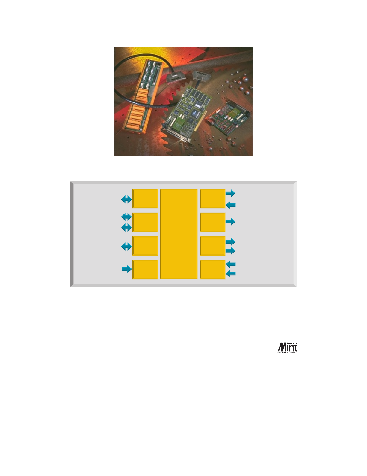
NextMove PCI is a high speed multi-axis intelligent motion controller for use in PCI bus based PC
systems.
Figure 2-1: NextMove PCI, Expansion Card and Breakout Unit
1MBaud serial comms for
high speed card to card
data transfer
High speed
serial
commun-
ications
Analog inputs4x12bit
differential 0-5V, 0-10V
+/-5V or +/-10V
Drive enable / general purpose relay
4 x Servo-amplifier demands
+/-10V, 14 bit
5 x Incremental Encoders,
3 channel, 7.5x10 edges/s max.
6
4Axesof
closed loop
Servo control
12
NextMove
Motion Controller
8
Inputs 0-4 second function
Hardware position latch &
fast interrupt input
32
2 CAN bus 1MBaud Industrial
Local Area Networks for
smart digital drives and I/O
PCI Bus
Interface
4k by 32 bit Dual Ported
RAM for high speed
communications with
PCI bus
4
4
4
5
4 Axes of
stepper
motors
4 x Step and direction signals
to control stepper drives 3MHz
maximum differential.
Digital
Outputs
12 x Digital outputs, opto-isolated
PNP or NPN, 12-24V, 350mA max
20
Digital
Inputs
20 x Digital inputs, opto-isolated
PNP or NPN, 12-24V. User
configurable as uncommitted
inputs, limit inputs, stop input.
Expansion
card
connector
16 bit expansion bus for
'next slot' expansion cards
Analog
Inputs
32 bit Digital Signal
Processor system.
Up to 8 axes of motion
control-4high
performance
closed loop servo,
4 stepper.
expandable to 12
servo or 12 stepper.
MINT or C
programming
language.
2Mb RAM.
Figure 2-2: Technical Overview

Product Overview
MN1277 04.2001
5
NextMove PCI features the MintTM motion control language. Mint is a structured form of Basic,
custom designed for motion control applications, either stepper or servo. It allows users to quickly
get up and running with simple motion control programs. In addition, Mint includes a wide range of
powerful commands for complex applications.
Included with NextMove PCI is the Baldor Motion Toolkit CD. This contains a number of utilities
and useful resources to get the most from you Mint controller. These include:
Mint Configuration Tool
is a rapid getting started and configuration utility designed for use with a
number of Mint v4 controllers. See the ‘Mint Configuration Tool Users Guide’ for details.
Mint WorkBench
is the IDE and user interface for communicating with a Mint controller.
Installing the Mint WorkBench will also install firmware (NMPCI.OUT) for NextMove PCI. See
the ‘Mint WorkBench Users Guide’ for details.
PC Developer Libraries
allow PC applications to be written that communicate with Mint
controllers. This includes C++ source and ActiveX interface. See the ‘Mint v4 PC Programming
Guide’ for details.
Embedded Developer Libraries
allow embedded C31 applications to be developed using the Texas
Instruments TMS320C3x compiler. See the ‘Mint v4 Embedded Programming Guide’ for details.
Mint Code Analyzer Tool
is a utility designed to help in the process of upgrading to Mint v4. The
utility will scan existing Mint and C application files and highlight the keywords and functions that
have been changed from older firmware versions. See the ‘Mint v4 Code Analyzer Tool’ manual for
details.

NextMove PCI Installation Manual
6
MN1277 04.2001

Hardware Guide
MN1277 04.2001
7
3. Hardware Guide
3
This chapter describes in detail the hardware interface to NextMove PCI.
NextMove PCI Installation Manual
8
MN1277 04.2001
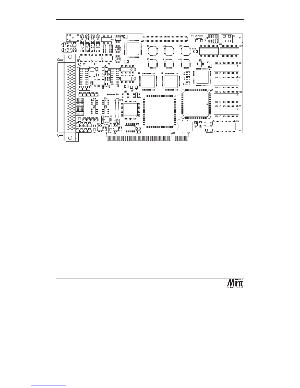
Figure 3-1: NextMove PCI Assembly
3.1 Operating Environment
The safe operation of this equipment depends upon its use in the appropriate environment:
•
At an altitude of
≤
2000m (6560ft) above sea level
•
In an ambient temperature of 0
°
C to 40°C (32°F to 104°F)
•
In relative humidity levels of 80% for temperatures up to 31
°
C (87°F) decreasingly linearly
to 50% relative humidity at 40
°
C (104°F), non-condensing
•
The pollution degree according to IEC664 shall not exceed 2
•
Power is supplied to the board via the PC power supply bus
•
The atmosphere shall not contain flammable gases or vapors
•
There shall not be abnormal levels of nuclear radiation or X-rays
Hardware Guide
MN1277 04.2001
9
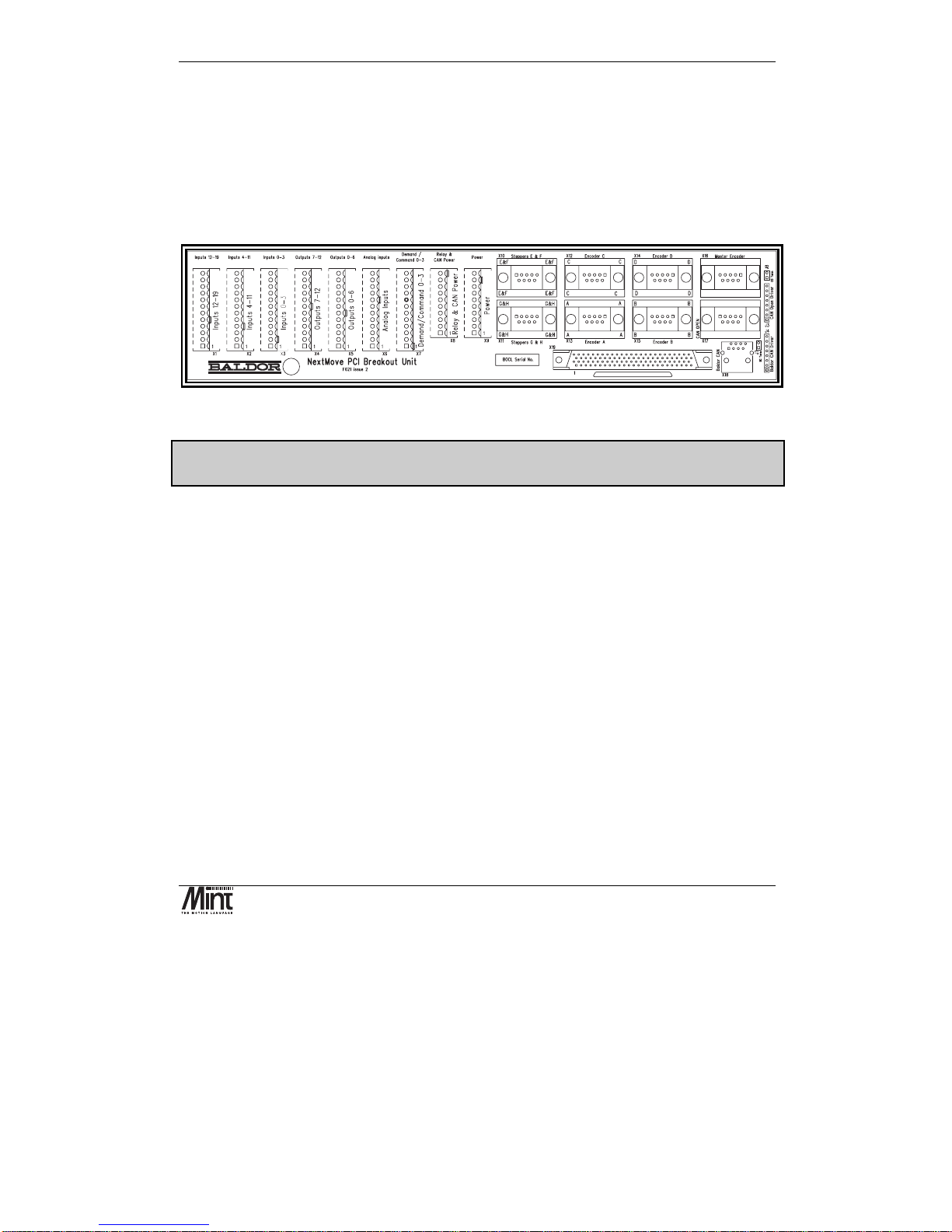
3.2 Connection to the PCB
All of the standard interfaces are brought out on the 100 pin D-type connector mounted on the metal
bracket. The PCB connector is an AMP787082-9. For the convenience of the user a kit consisting of
a cable assembly and a DIN rail mounting Breakout Unit is available. There are currently two types
of Breakout Unit available. The standard type uses single part connectors (Baldor part no. PCI003-
501). A unit with two part connectors (Baldor part no. PCI003-502) is also available. These are
described in Section 5.4.
Figure 3-2: NextMove PCI Breakout Unit
For ease of transition from NextMove PC to NextMove PCI, a converter is available to allow
NextMove PC Breakout Unit to be used (contact factory).
See section 6.3 for connector details.
3.3 Digital I/O
There are a total of 20 general purpose digital inputs and 12 general purpose digital outputs. The
digital inputs are software configurable for any one of the following functions:
•
forward limit
(end of travel) input on any axis.
•
reverse limit
(end of travel) input on any axis.
•
home input
on any axis.
•
drive error
input on any axis.
•
stop input
(controlled) on any axis.
The inputs can be programmed such that any of the axes can share the same input if necessary.
The inputs are also programmable in software for edge triggered (positive and negative) and their
active level.
The digital outputs can be programmed as a
drive enable
output for any axis or
general error
output
. Again, axes can share the same output. The active level of the output is also software
programmable.
NextMove PCI Installation Manual
10
MN1277 04.2001
As well as the general purpose I/O, NextMove PCI also supports fast position latch inputs (IN0 to
IN3) and optionally, digital outputs for stepper control. The stepper outputs can be programmed in
software as general purpose outputs. The stepper outputs are discussed in section 3.5.
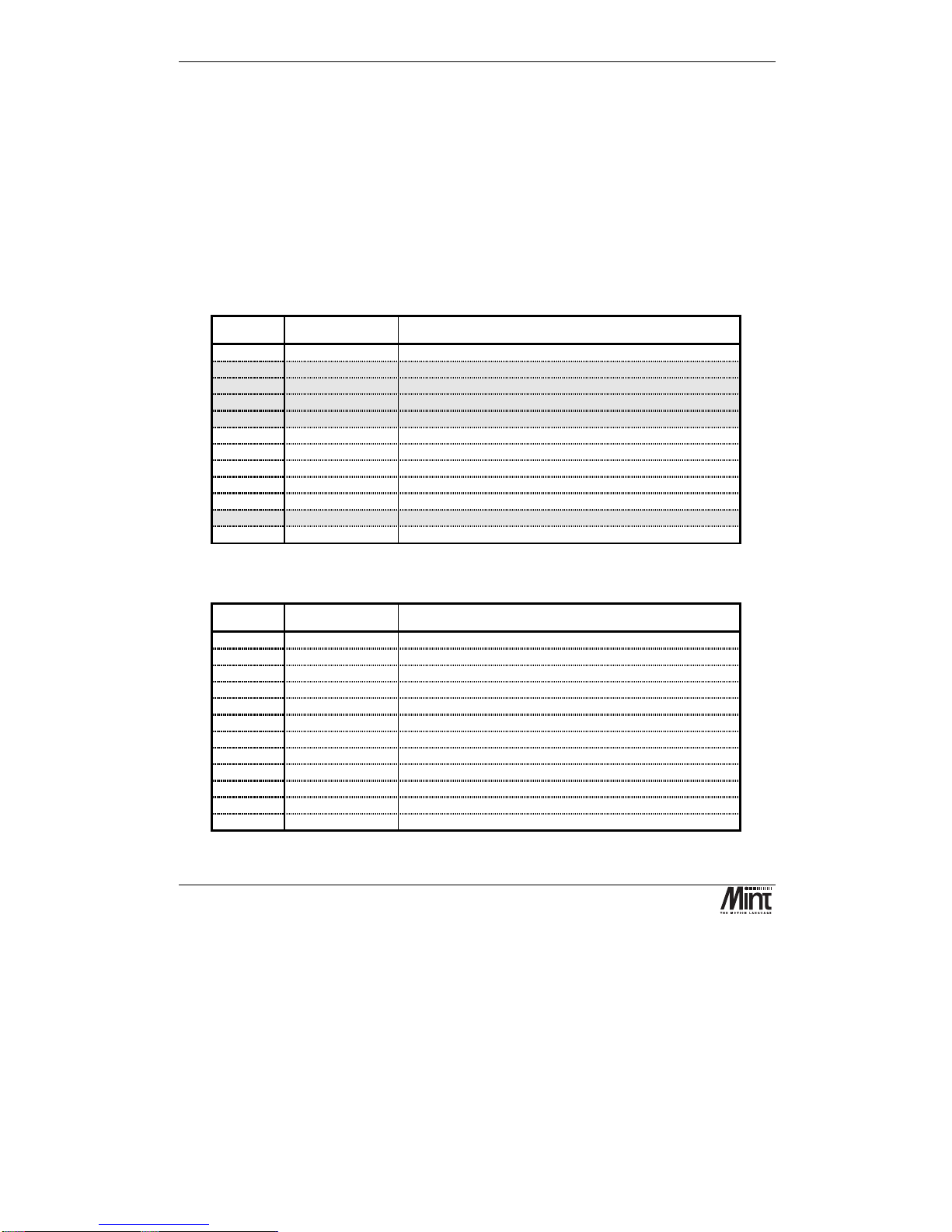
3.3.1 Standard Digital Inputs
There are sixteen optically isolated standard digital inputs arranged as two banks of 8. Each bank has
its own common rail that must be referred to system ground and cannot be left disconnected. Each
bank can have a separate supply or voltage level.
These inputs are available on connectors X1 and X2 on the NextMove PCI Breakout Unit.
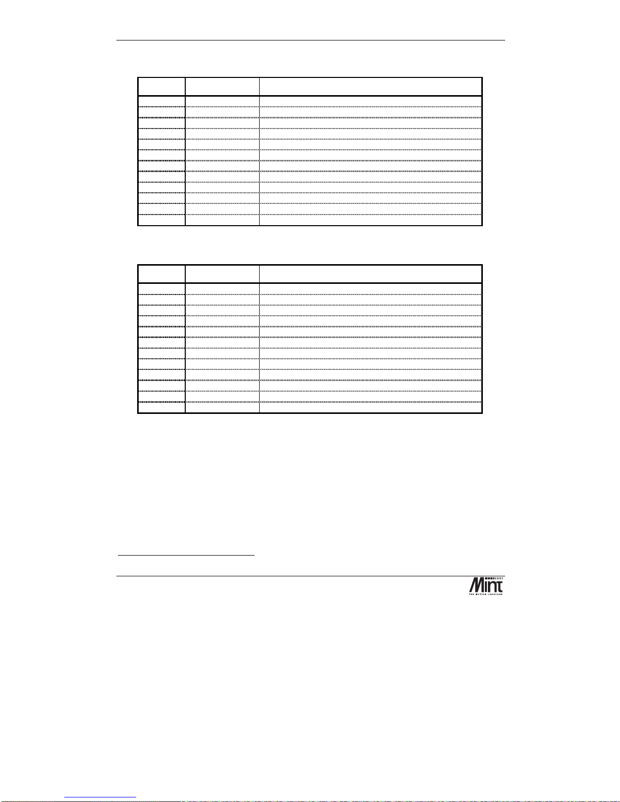
X2: Digital Inputs 4 to 11
Pin Signal Function
1
Chassis
Shield connection
2
DIG_IN_4
Digital input 4 (referenced to Common0-7)
3
DIG_IN_5
Digital input 5 (referenced to Common0-7)
4
DIG_IN_6
Digital input 6 (referenced to Common0-7)
5
DIG_IN_7
Digital input 7 (referenced to Common0-7)
6
DIG_IN_8
Digital input 8 (referenced to Common8-19)
7
DIG_IN_9
Digital input 9 (referenced to Common8-19)
8
DIG_IN_10
Digital input 10 (referenced to Common8-19)
9
DIG_IN_11
Digital input 11 (referenced to Common8-19)
10
Chassis
Shield connection
11
Common0-7
Common for inputs 0-7
12
Common8-19
Common for inputs 8-19
X1: Digital Inputs 12 to 19
Pin Signal Function
1
Chassis
Shield connection
2
DIG_IN_12
Digital input 12 (referenced to Common8-19)
3
DIG_IN_13
Digital input 13 (referenced to Common8-19)
4
DIG_IN_14
Digital input 14 (referenced to Common8-19)
5
DIG_IN_15
Digital input 15 (referenced to Common8-19)
6
DIG_IN_16
Digital input 16 (referenced to Common8-19)
7
DIG_IN_17
Digital input 17 (referenced to Common8-19)
8
DIG_IN_18
Digital input 18 (referenced to Common8-19)
9
DIG_IN_19
Digital input 19 (referenced to Common8-19)
10
Chassis
Shield connection
11
n/c
Not connected
12
Common8-19
Common for inputs 8-19
Hardware Guide
MN1277 04.2001
11
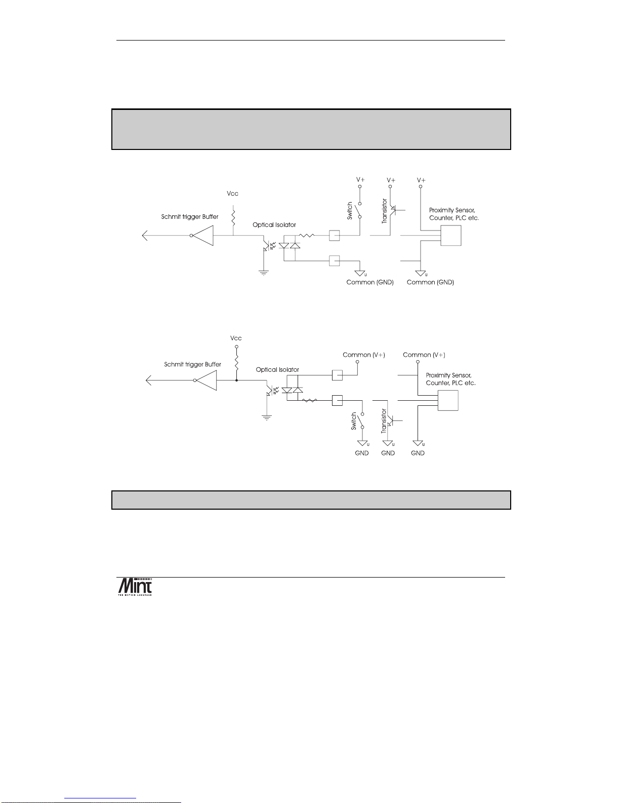
The digital inputs use ac opto-isolators. The switching level is 12 to 24V (supplied by the user). If
the driving signal switches high with reference to a low ground, the driving signal ground should be
connected to the input common. If the driving signal switches low with reference to a driving signal
supply rail, the driving supply rail should be connected to the input common.
When using the NextMove PC Breakout Unit and converter board (OPT025-506) the two
banks must use USR-V+ and USR-GND. Jumpers on the converter board select which voltage
is connected to the common rails.
Figure 3-3 shows a digital input connected to high-side (PNP) driving signals.
Figure 3-3:Digital Inputs, PNP configuration
Figure 3-4 shows a digital input connected to low-side (NPN) driving signals.
Figure 3-4: Digital Inputs, NPN Configuration
Note: Sustained voltages above 28V will damage the inputs.
The inputs are conditioned using low pass RC filters and Schmitt trigger buffers. An input pulse
must have a duration of at least 1ms (one software scan) to guarantee acceptance by the application
program when configured as edge triggered.
As with all good wiring practice, the use of screened cable is recommended.
NextMove PCI Installation Manual
12
MN1277 04.2001
Associated Mint keywords are:
#INx, INPUTACTIVELEVEL, IN, INx, INPUTMODE, INPUTNEGTRIGGER,
INPUTPOSTRIGGER, INSTATE
3.3.2 Fast Position Interrupts: Digital Inputs 0 to 3
Digital inputs
DIG_IN_0
to
DIG_IN_3
can be used as high speed position latches.
The inputs are available on connector X3 on the NextMove PCI Breakout Unit.
Pin Signal Function
1
DIG_IN_0
Digital input 0
2
Common0-7
Return for inputs 0-7
3
Chassis
Shield connection
4
DIG_IN_1
Digital input 1
5
Common0-7
Return for inputs 0-7
6
Chassis
Shield connection
7
DIG_IN_2
Digital input 2
8
Common0-7
Return for inputs 0-7
9
Chassis
Shield connection
10
DIG_IN_3
Digital input 3
11
Common0-7
Return for inputs 0-7
12
Chassis
Shield connection
Digital inputs 0 to 3 are sensitive to noise. The use of screened twisted pair cabling is recommended.
The fast position inputs are routed through a programmable cross point switch which allows any
input to cause the position of any combination of axes to be latched within 1µs - a feature essential
in high speed print registration applications. When triggered, the position is captured and a user
interrupt can be triggered to handle this event.
See section ‘Fast Position Latch’ in the ‘Mint v4 Programming Guide’ for more details.
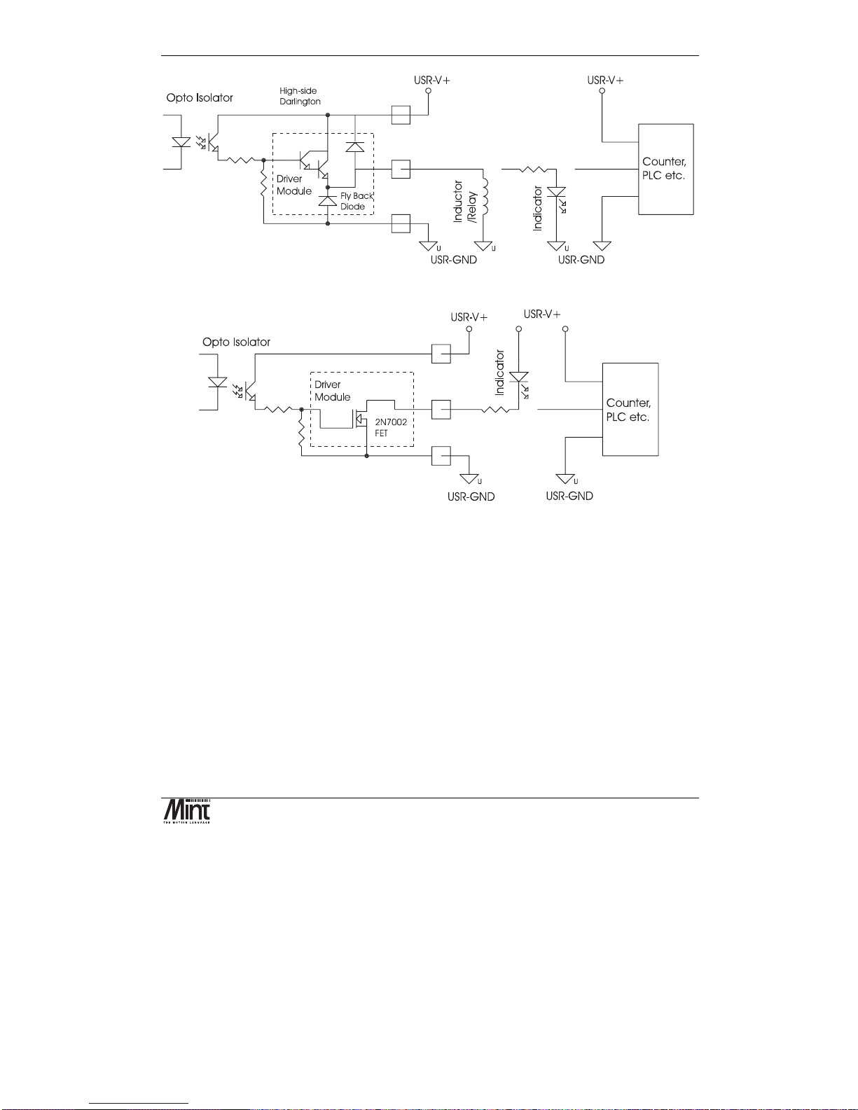
3.3.3 Digital Outputs
There are twelve opto-isolated digital outputs driven via a module fitted to NextMove PCI. Two
modules types are available:
Current sourcing, ‘PNP’ Darlington with overcurrent and short circuit protection (fitted as standard).
Current sinking, ‘NPN’, open drain N-channel MOSFET.
Hardware Guide
MN1277 04.2001
13
Figure 3-5: Digital Outputs with Current Sourcing Module
Figure 3-6: Digital Outputs with Current Sinking Module
The outputs are available on connectors X4 and X5 on the NextMove PCI Breakout Unit.
NextMove PCI Installation Manual
14
MN1277 04.2001
X5: Digital Outputs 0-5
Pin Signal Function
1
Chassis
Shield connection
2
DIG_OUT_0
Digital output 0
3
DIG_OUT_1
Digital output 1
4
DIG_OUT_2
Digital output 2
5
DIG_OUT_3
Digital output 3
6
DIG_OUT_4
Digital output 4
7
DIG_OUT_5
Digital output 5
8
n/c
Not connected
9
n/c
Not connected
10
Chassis
Shield connection
11
USR-V+
∗∗∗∗
Output power supply power
12
USR-GND
Output power supply ground
X4: Digital Outputs 6-11
Pin Signal Function
1
Chassis
Shield connection
2
DIG_OUT_6
Digital output 6
3
DIG_OUT_7
Digital output 7
4
DIG_OUT_8
Digital output 8
5
DIG_OUT_9
Digital output 9
6
DIG_OUT_10
Digital output 10
7
DIG_OUT_11
Digital output 11
8
n/c
Not connected
9
n/c
Not connected
10
Chassis
Shield connection
11
USR-V+
∗∗∗∗
Output power supply power
12
USR-GND
Output power supply ground
Note that USR-GND must be tied to system ground - it must not be left disconnected. When using
current sourcing outputs, the user must supply 12-24V DC between USR-V+ and USR-GND.
The current sink / source capability of the NPN and PNP outputs respectively is 50mA.
As with all good wiring practice, the use of screened cable is recommended.
Associated Mint keywords are:
OUTPUTACTIVELEVEL, OUT, OUTx
∗
This power must be supplied externally
Hardware Guide
MN1277 04.2001
15
3.4 Analog I/O
3.4.1 Analog Inputs
Four 12-bit resolution analog inputs are provided. The inputs are available on connector X6 on the
NextMove PCI Breakout Unit.
X6: Analog Inputs
Pin Signal Function
1
AGND
Analog ground
2
AIN_0+
Analog input 0 positive input
3
AIN_0-
Analog input 0 negative input
6
Chassis
Shield connection
1
AGND
Analog ground
4
AIN_1+
Analog input 1 positive input
5
AIN_1-
Analog input 1 negative input
6
Chassis
Shield connection
7
AGND
Analog ground
8
AIN_2+
Analog input 2 positive input
9
AIN_2-
Analog input 2 negative input
12
Chassis
Shield connection
7
AGND
Analog ground
10
AIN_3+
Analog input 3 positive input
11
AIN_3-
Analog input 3 negative input
12
Chassis
Shield connection
Shielded twisted pairs should be used and connected as shown. The shield connection should be
made at one end only. If the source of the signal is already grounded there is no need to connect
AGND (shown dotted).
The analog inputs pass through a differential buffer and second order Butterworth filter with a 1kHz
cut-off frequency. Both the filtered and unfiltered signals are converted using a multiplexed 12-bit
ADC, which has four software-selectable input voltage ranges: 0-5V, ±5V, 0-10V and ±10V.
The analog inputs are sampled by Mint at a rate of 2.5kHz.

NextMove PCI Installation Manual
16
MN1277 04.2001
Figure 3-7: Analog Buffer and Range Selection
Differential Mode:
The analog inputs are all true differential which means that the signal is measured relative to a
reference rather than the controller ground. The differential mode makes the system more immune to
common mode noise picked up in the cabling.
Figure 3-8: Analog Input, Differential Connection
Associated Mint keywords are:
ADCMODE, ADC
3.4.2 Analog Outputs (Drive Command)
There are four 14bit resolution analog outputs. The outputs are available on connector X7 on the
NextMove PCI Breakout Unit. By default Mint™ and the Mint™ Motion Library use the analog
outputs to control servo drives. Outputs 0 to 3 correspond to axes 0 to 3 respectively.

Hardware Guide
MN1277 04.2001
17
X7: Drive Signals (X7)
Pin Signal Function
1
DEMAND_0
Demand/command signal for axis 0
2
AGND
Analog ground
3
Chassis
Shield connection
4
DEMAND_1
Demand/command signal for axis 1
5
AGND
Analog ground
6
Chassis
Shield connection
7
DEMAND_2
Demand/command signal for axis 2
8
AGND
Analog ground
9
Chassis
Shield connection
10
DEMAND_3
Demand/command signal for axis 3
11
AGND
Analog ground
12
Chassis
Shield connection
Demand signals are outputs to the servo amplifiers. Shielded twisted pairs should be used and
connected as shown. The shield connection should be made at one end only.
The outputs have a range of ±10V (1.22mV per bit).
Outputs 0 to 3 are inverted and buffered by op-amps, and may be used to drive loads of
≥
10kΩ. The
outputs are referenced to PC system ground. DAC channels 4-7 are summed with the first three
outputs with 1/16
th
of the gain i.e. 1/16th of the DAC channel 4 output is added to the DAC channel 0
output, and so on. DAC channels 4 – 7 can therefore be used to trim channels 0 - 3 (trim range
±0.625V).
The analog output buffer circuit is shown below.
Figure 3-9: Analog Output Buffer
Associated Mint keywords are:
DACLIMITMAX, DAC, DACMODE, DACOFFSET

NextMove PCI Installation Manual
18
MN1277 04.2001
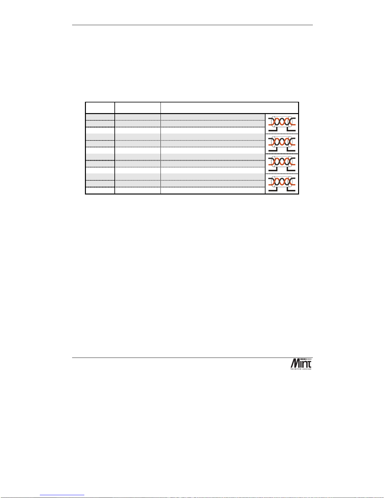
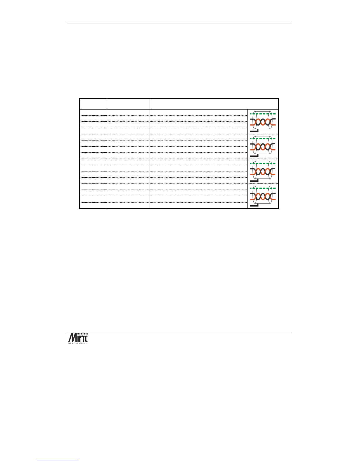
3.5 Encoder Interface
Up to five incremental encoders may be connected to NextMove PCI. The signals are brought out
onto the NextMove PCI Breakout Unit via signals X12, X13, X14, X15 and X16. These are 9-pin
D-type female sockets. The shell of the connector is connected to chassis. When possible, the use of
individually screened twisted pair cable is recommended.
Figure 3-10: Encoder Connector
Pin Signal Function Cabling
1
Encoder V+
1
Power to the encoder
7
gnd
Power and signal ground
5
chA
Channel A true signal
9
!chA
Channel A complement signal
8
chB
Channel B true signal
3
!chB
Channel B complement signal
2
index
Index true signal (channel I or Z or C)
6
!index
Index complement signal (channel I or Z or C)
4
chassis
Chassis connection
Shell
chassis
Screen
The encoders must provide either complementary TTL or differential line drive (RS422/RS485)
signals to operate with NextMove PCI. The input circuit uses MAX3095 differential line receivers
with a pull ups and terminators. Each encoder channel has inputs A, B and Index.
1
The encoder power rail on X9 must be connected to VCC or supplied externally
Hardware Guide
MN1277 04.2001
19
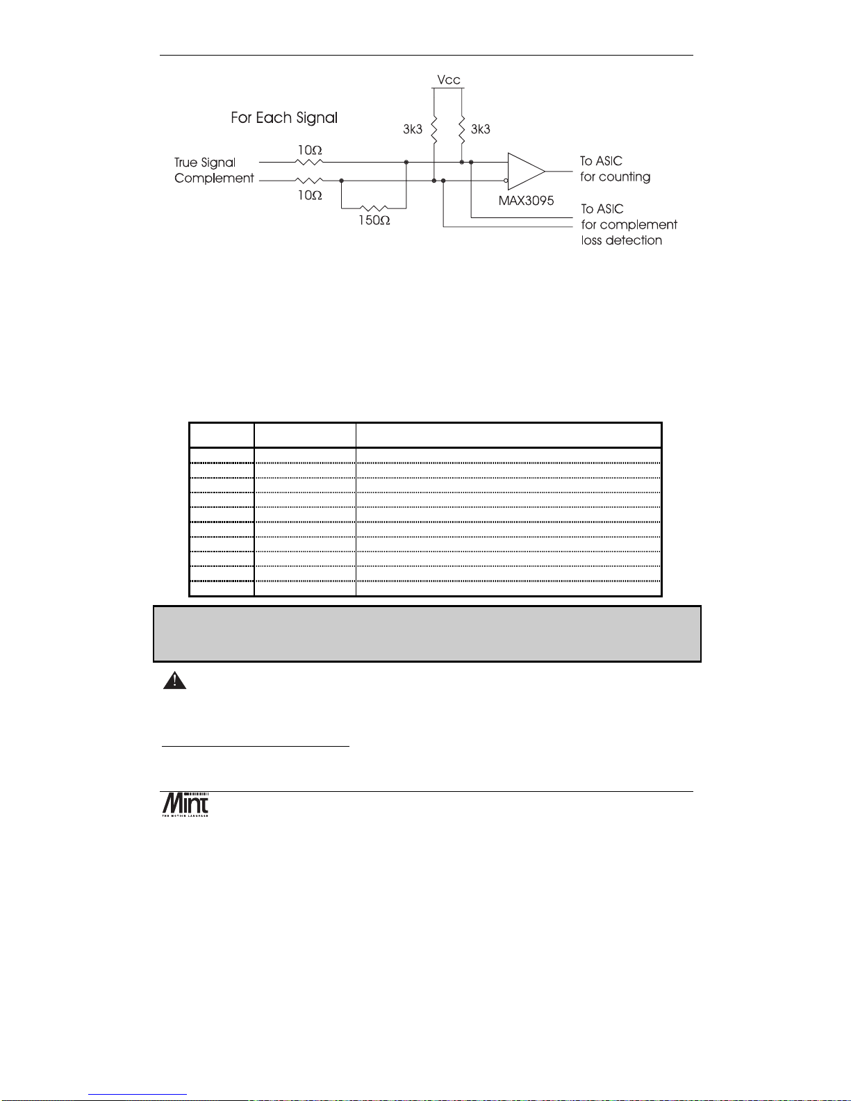
Figure 3-11: Encoder Line Receiver Interface
The maximum input frequency of the encoder input is 7.5 million quadrature counts per second, one
count per edge. This equates to a maximum frequency for the A and B signals of 1.87MHz.
Within Mint, ‘complement loss detection’ is highlighted as an ‘encoder transition warning’ within
the AXISWARNING keyword. It must be enabled with the AXISWARNINGDISABLE keyword.
Associated Mint keywords are:
ENCODER, ENCODERSCALE, ENCODERVEL, ENCODERWRAP, POS, SCALE, VEL
X9: Encoder Power
Pin Signal Function
1
Vcc
5V power connection (from the PC)
2
Vcc
5V power connection (from the PC)
3
Encoder V+
1
Power to the encoder connectors (normally +5V)
4
Encoder V+
1
Power to the encoder connectors (normally +5V)
5
GND
Digital ground (from the PC)
6
GND
Digital ground (from the PC)
7
USR-V+
2
Output power supply
8
USR-V+
2
Output power supply
9
USR-GND
Output power supply ground
10
USR-GND
Output power supply ground
Note: The encoder power can be linked to Vcc to supply the encoders with +5V, provided that
the total current consumption of the encoders does not exceed 500mA. For externally powered
encoders, the maximum is 30V provided total current consumption does not exceed 3A.
Warning – Encoder power must be connected before switching on.
If the encoders are not powered then there will be no position feedback which could cause violent
motion of the motor shaft if the system is enabled.
1
Encoder V+ must be connected to VCC or supplied externally
2
USR-V+ must be supplied externally
NextMove PCI Installation Manual
20
MN1277 04.2001
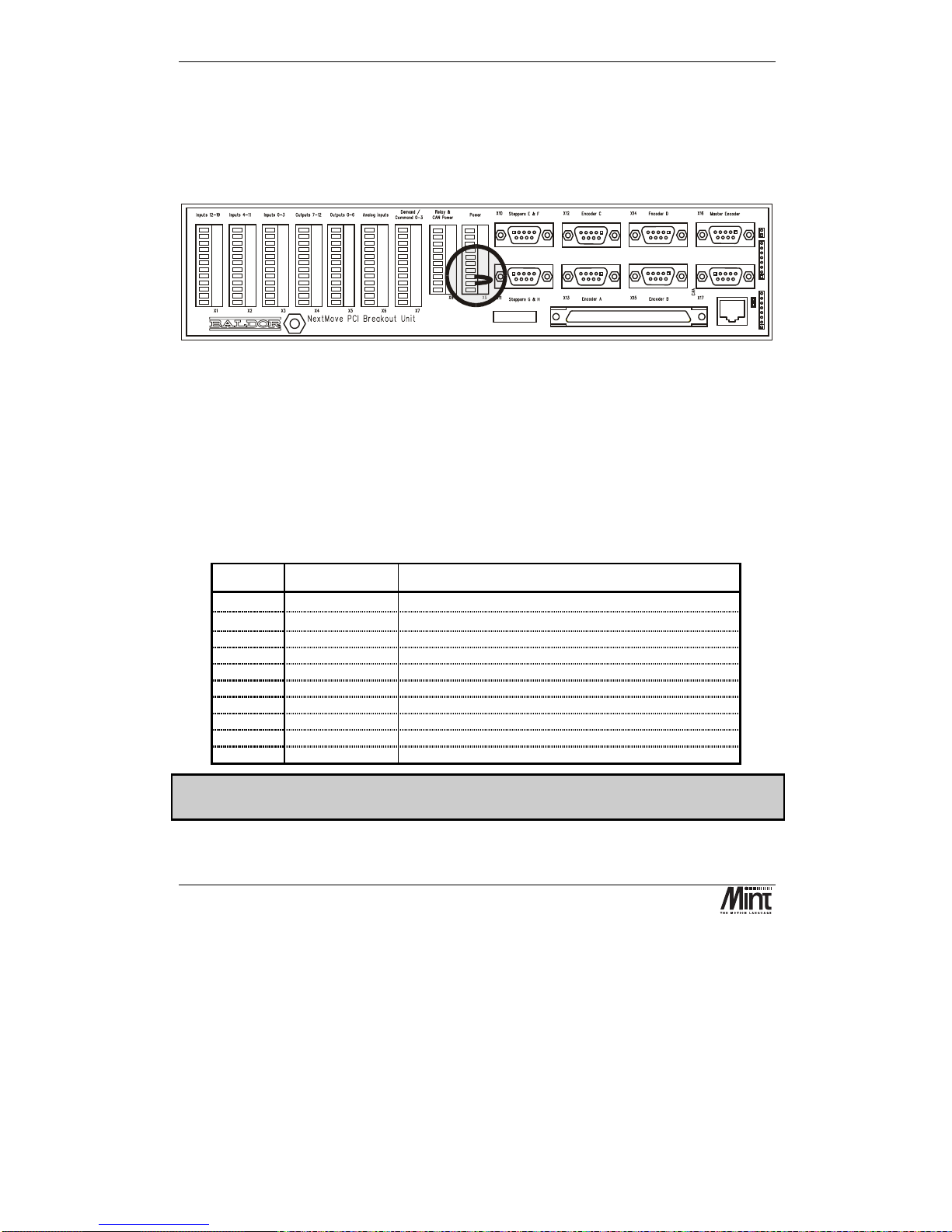
The encoder connectors are powered from pins 3 and 4 of the power connector X9. This voltage is
with respect to digital ground. This connection scheme is to allow correct powering of the encoders
where the required voltage is not 5V and/or the total current exceeds 500mA. For encoders
requiring 5V power at a total current, for all encoders, of 500mA or less, the encoder V+ rail may be
connected to V
CC
by linking pins 2 (VCC) and 3 (Encoder V+) of X9. A link is fitted in this position
at the factory.
Baldor CAN
Note:- Replacing issue 1 units
If replacing issue 1 breakout units, connections to pins 3, 4, 5 and 6 of the issue 1 unit power
connector(J10) must be connected to pins 5 and 6 only of the issue 2 unit power connector (X9).
3.6 Relay
A single pole change-over relay is included on the card to provide a volt-free contact for system
enabling or general use. The relay signals are available on the NextMove PCI Breakout Unit via
connector X8.
X8: Relay and CAN Power
Pin Signal Function
1
CAN-V+ 1
Power input for CAN 1 network (
CAN
open
). (12-24V)
2
CAN-GND 1
Ground for CAN 1 network (
CAN
open
)
3
CAN-V+ 2
Power input for CAN 2 network (Baldor CAN) (12-24V)
4
CAN-GND 2
Ground for CAN 2 network (Baldor CAN)
5
Relay-NC
Normally closed relay connection
6
Relay-NO
Normally open relay connection
7
Relay-COM
Common relay connection
8
USR-V+
2
Output power supply power
9
USR-GND
Output power supply ground
10
Chassis
Shield connection
Only isolated CAN channels require 24V to power to opto-isolation. Non isolated CAN
channels must not be powered.
The relay pins are isolated from any internal circuits on the NextMove PCI.
 Loading...