


MN1277 04.2001
NextMove PCI
Installation Manual
MN1277
Issue 2.3

NextMove PCI Installation Manual
ii
MN1277 04.2001
.

Copyright
MN1277 04.2001
iii
Copyright Baldor UK Ltd © 2001. All rights reserved.
This manual is copyrighted and all rights are reserved. This document or attached software may not, in whole or in part, be
copied or reproduced in any form without the prior written consent of Baldor UK.
Baldor Optimised Control makes no representations or warranties with respect to the contents hereof and specifically
disclaims any implied warranties of fitness for any particular purpose. The information in this document is subject to change
without notice. Baldor UK assumes no responsibility for any errors that may appear in this document.
MINT
™
is a registered trademark of Baldor UK Ltd.
Windows 95, Windows 98 and Windows NT are registered trademarks of the Microsoft Corporation.
Limited Warranty
For a period of two (2) years from the date of original purchase, BALDOR will repair or replace without charge controls and
accessories which our examination proves to be defective in material or workmanship. This warranty is valid if the unit has
not been tampered with by unauthorized persons, misused, abused, or improperly installed and has been used in accordance
with the instructions and/or ratings supplied. This warranty is in lieu of any other warranty or guarantee expressed or
implied. BALDOR shall not be held responsible for any expense (including installation and removal), inconvenience, or
consequential damage, including injury to any person or property caused by items of our manufacture or sale. (Some
countries and U.S. states do not allow exclusion or limitation of incidental or consequential damages, so the above exclusion
may not apply.) In any event, BALDOR’s total liability, under all circumstances, shall not exceed the full purchase price of
the control. Claims for purchase price refunds, repairs, or replacements must be referred to BALDOR with all pertinent data
as to the defect, the date purchased, the task performed by the control, and the problem encountered. No liability is assumed
for expendable items such as fuses.
Goods may be returned only with written notification including a BALDOR Return Authorization Number and any return
shipments must be prepaid.
Baldor UK Ltd
Mint Motion Centre
6 Bristol Distribution Park
Hawkley Drive
Bristol
BS32 0BF
U.K.
Telephone: +44 (0) 1454 850 000
Fax: +44 (0) 1454 859 001
Web site: www.baldor.co.uk
Sales email: sales@baldor.co.uk
Support email: technical.support@baldor.co.uk
Baldor Electric Company
Telephone: +1 501 646 4711
Fax: +1 501 648 5792
email: sales@baldor.com
web site: www.baldor.com
Baldor ASR GmbH
Telephone: +49 (0) 89 90508-0
Fax: +49 (0) 89 90508-492
Baldor ASR AG
Telephone: +41 (0) 52 647 4700
Fax: +41 (0) 52 659 2394
Australian Baldor Pty Ltd
Telephone: +61 2 9674 5455
Fax: +61 2 9674 2495
Baldor Electric (F.E.) Pte Ltd
Telephone: +65 744 2572
Fax:+65 747 1708

NextMove PCI Installation Manual
iv
MN1277 04.2001

Safety Information
MN1277 04.2001
v
Safety Notice
:
Only qualified personnel should attempt the start-up procedure
or troubleshoot this equipment.
This equipment may be connected to other machines that have rotating parts or parts that are
controlled by this equipment. Improper use can cause serious or fatal injury. Only qualified
personnel should attempt to start-up, program or troubleshoot this equipment.
Precautions:
WARNING: Do not touch any circuit board, power device
or electrical connection before you first
ensure that no high voltage present at this
equipment or other equipment to which it is
connected. Electrical shock can cause
serious or fatal injury. Only qualified
personnel should attempt to start-up,
program or troubleshoot this equipment.
WARNING: Be sure that you are completely familiar with
the safe operation of this equipment. This
equipment may be connected to other
machines that have rotating parts or parts
that are controlled by this equipment.
Improper use can cause serious or fatal
injury. Only qualified personnel should
attempt to program, start-up or troubleshoot
this equipment.
WARNING: Be sure that you are completely familiar with
the safe programming of this equipment.
This equipment may be connected to other
machines that have rotating parts or parts
that are controlled by this equipment.
Improper programming of this equipment can
cause serious or fatal injury. Only qualified
personnel should attempt to program, startup or troubleshoot this equipment.
WARNING: Be sure all wiring complies with the National
Electrical Code and all regional and local
codes. Improper wiring may result in unsafe
conditions.
NextMove PCI Installation Manual
vi
MN1277 04.2001
WARNING: The stop input to this equipment should not
be used as the single means of achieving a
safety critical stop. Drive disable, motor
disconnect, motor brake and other means
should be used as appropriate. Only qualified
personnel should attempt to program, startup or troubleshoot this equipment.
WARNING: Improper operation or programming of the
control may cause violent motion of the
motor shaft and driven equipment. Be certain
that unexpected motor shaft movement will
not cause injury to personnel or damage to
equipment. Peak torque of several times the
rated motor torque can occur during control
failure.
WARNING: The motor shaft will rotate during the homing
procedure. Be certain that unexpected motor
shaft movement will not cause injury to
personnel or damage to equipment.
CAUTION: To prevent equipment damage, be certain that
the input power has correctly sized protective
devices installed.
CAUTION: To prevent equipment damage, be certain that
input and output signals are powered and
referenced correctly.
CAUTION: To ensure reliable performance of this
equipment be certain that all signals to/from
the controller are shielded correctly.
CAUTION: Avoid locating this equipment above or
beside heat generating equipment or below
water steam pipes.
CAUTION: Avoid locating this equipment in the vicinity
of corrosive substances or vapors, metal
particles and dust.

Manual Revision History
MN1277 04.2001
vii
Manual Revision History
Issue Date BOCL Reference Comments
1.0 Nov 1999 UM00506-000 First release of Hardware Guide based on
NextMove PC Manual. Updated sections are:
NextMove PCI Overview
NextMove PCI Hardware Guide
1.1 July 1999 UM00506-001 Changes for i2 Breakout Unit
1.2 Sept 1999 UM00506-002 Substantial textual amendments
2.0 Nov 1999 UM00506-003 Added detail on using the controller
2.1 March 2000 UM00506-004 Updated for NextMove PCI issue 4
2.2 August 2000 UM00506-005 Updated for Mint v4.2 release
2.3 April 2001 UM00506-006 Updates from 04.2001 errata

NextMove PCI Installation Manual
viii
MN1277 04.2001

Contents
MN1277 04.2001
ix
Read Me First ............................................................................. 1
1.1 Key to Symbols Used in this Manual.........................................................2
Product Overview ...................................................................... 3
Hardware Guide ......................................................................... 7
3.1 Operating Environment.............................................................................8
3.2 Connection to the PCB .............................................................................9
3.3 Digital I/O..................................................................................................9
3.4 Analog I/O ..............................................................................................15
3.5 Encoder Interface ...................................................................................18
3.6 Relay ......................................................................................................19
3.7 Stepper Drive Outputs ............................................................................21
3.8 CAN Bus.................................................................................................22
3.9 Reset State.............................................................................................24
3.10 LEDs.......................................................................................................25
3.11 NextMove PCI Expansion Card ..............................................................26
3.12 Miscellaneous.........................................................................................28
3.13 NextMove PCI Breakout Unit ..................................................................28
Operation and Setup................................................................ 37
4.1 Installing NextMove PCI..........................................................................38
4.2 Baldor Motion Toolkit CD........................................................................40
4.3 Configuring your System ........................................................................42
4.4 Servo Setup............................................................................................46
4.5 Stepper Setup.........................................................................................59
4.6 Methods of Programming .......................................................................61
4.7 Documentation ....................................................................................... 61
4.8 Mint.........................................................................................................62

NextMove PCI Installation Manual
x
MN1277 04.2001
4.9 Motion.....................................................................................................70
Options and Accessories ........................................................ 71
5.1 NextMove PCI.........................................................................................72
5.2 NextMove PCI Expansion Card ..............................................................72
5.3 Digital Output Modules ...........................................................................73
5.4 Breakout Unit..........................................................................................74
5.5 NextMove PC System Adapter ...............................................................75
5.6 Spares ....................................................................................................75
5.7 CAN Nodes.............................................................................................76
5.8 NextMove PCI CAN Bracket Board.........................................................77
5.9 Encoder Splitter/Buffer Board .................................................................79
Specifications and Product Data ............................................ 81
6.1 Machine Control I/O................................................................................82
6.2 Miscellaneous and Mechanical Specification ..........................................83
6.3 100-Pin Connector..................................................................................84
6.4 EMC & CE Marking..................................................................................86
Trouble Shooting Guide .......................................................... 89
Bibliography............................................................................. 93

Read Me First
MN1277 04.2001
1
1. Read Me First
1
Details of the symbols used throughout this document.

NextMove PCI Installation Manual
2
MN1277 04.2001
This manual contains information for installing and commissioning the NextMove PCI intelligent
motion controller.
1.1 Key to Symbols Used in this Manual
Throughout this section various icons and conventions are used to indicate specific functions:
The screwdriver icon indicates that it is necessary to make a physical connection to
NextMove PCI by way of screw terminations.
The disk icon together with filename is used to indicate that a Mint program ( the motion
control language used to program NextMove PCI ) should be downloaded to the controller.
The prompt icon indicates that the following commands should be typed in directly to the
terminal at the Mint P> or C> prompt.
[Ctrl]+[E]
Type
Ctrl
and E at the same time.

Product Overview
MN1277 04.2001
3
2. Product Overview
2
A brief overview of NextMove PCI and the software tools available on the
Baldor Motion Toolkit.
NextMove PCI Installation Manual
4
MN1277 04.2001
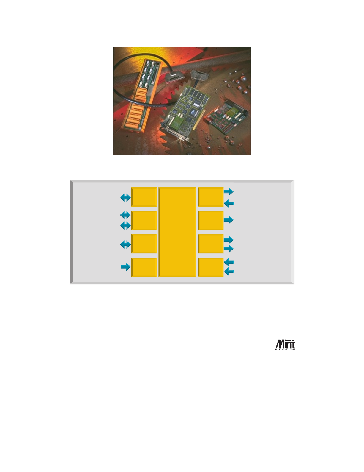
NextMove PCI is a high speed multi-axis intelligent motion controller for use in PCI bus based PC
systems.
Figure 2-1: NextMove PCI, Expansion Card and Breakout Unit
1MBaud serial comms for
high speed card to card
data transfer
High speed
serial
commun-
ications
Analog inputs4x12bit
differential 0-5V, 0-10V
+/-5V or +/-10V
Drive enable / general purpose relay
4 x Servo-amplifier demands
+/-10V, 14 bit
5 x Incremental Encoders,
3 channel, 7.5x10 edges/s max.
6
4Axesof
closed loop
Servo control
12
NextMove
Motion Controller
8
Inputs 0-4 second function
Hardware position latch &
fast interrupt input
32
2 CAN bus 1MBaud Industrial
Local Area Networks for
smart digital drives and I/O
PCI Bus
Interface
4k by 32 bit Dual Ported
RAM for high speed
communications with
PCI bus
4
4
4
5
4 Axes of
stepper
motors
4 x Step and direction signals
to control stepper drives 3MHz
maximum differential.
Digital
Outputs
12 x Digital outputs, opto-isolated
PNP or NPN, 12-24V, 350mA max
20
Digital
Inputs
20 x Digital inputs, opto-isolated
PNP or NPN, 12-24V. User
configurable as uncommitted
inputs, limit inputs, stop input.
Expansion
card
connector
16 bit expansion bus for
'next slot' expansion cards
Analog
Inputs
32 bit Digital Signal
Processor system.
Up to 8 axes of motion
control-4high
performance
closed loop servo,
4 stepper.
expandable to 12
servo or 12 stepper.
MINT or C
programming
language.
2Mb RAM.
Figure 2-2: Technical Overview

Product Overview
MN1277 04.2001
5
NextMove PCI features the MintTM motion control language. Mint is a structured form of Basic,
custom designed for motion control applications, either stepper or servo. It allows users to quickly
get up and running with simple motion control programs. In addition, Mint includes a wide range of
powerful commands for complex applications.
Included with NextMove PCI is the Baldor Motion Toolkit CD. This contains a number of utilities
and useful resources to get the most from you Mint controller. These include:
Mint Configuration Tool
is a rapid getting started and configuration utility designed for use with a
number of Mint v4 controllers. See the ‘Mint Configuration Tool Users Guide’ for details.
Mint WorkBench
is the IDE and user interface for communicating with a Mint controller.
Installing the Mint WorkBench will also install firmware (NMPCI.OUT) for NextMove PCI. See
the ‘Mint WorkBench Users Guide’ for details.
PC Developer Libraries
allow PC applications to be written that communicate with Mint
controllers. This includes C++ source and ActiveX interface. See the ‘Mint v4 PC Programming
Guide’ for details.
Embedded Developer Libraries
allow embedded C31 applications to be developed using the Texas
Instruments TMS320C3x compiler. See the ‘Mint v4 Embedded Programming Guide’ for details.
Mint Code Analyzer Tool
is a utility designed to help in the process of upgrading to Mint v4. The
utility will scan existing Mint and C application files and highlight the keywords and functions that
have been changed from older firmware versions. See the ‘Mint v4 Code Analyzer Tool’ manual for
details.

NextMove PCI Installation Manual
6
MN1277 04.2001

Hardware Guide
MN1277 04.2001
7
3. Hardware Guide
3
This chapter describes in detail the hardware interface to NextMove PCI.
NextMove PCI Installation Manual
8
MN1277 04.2001
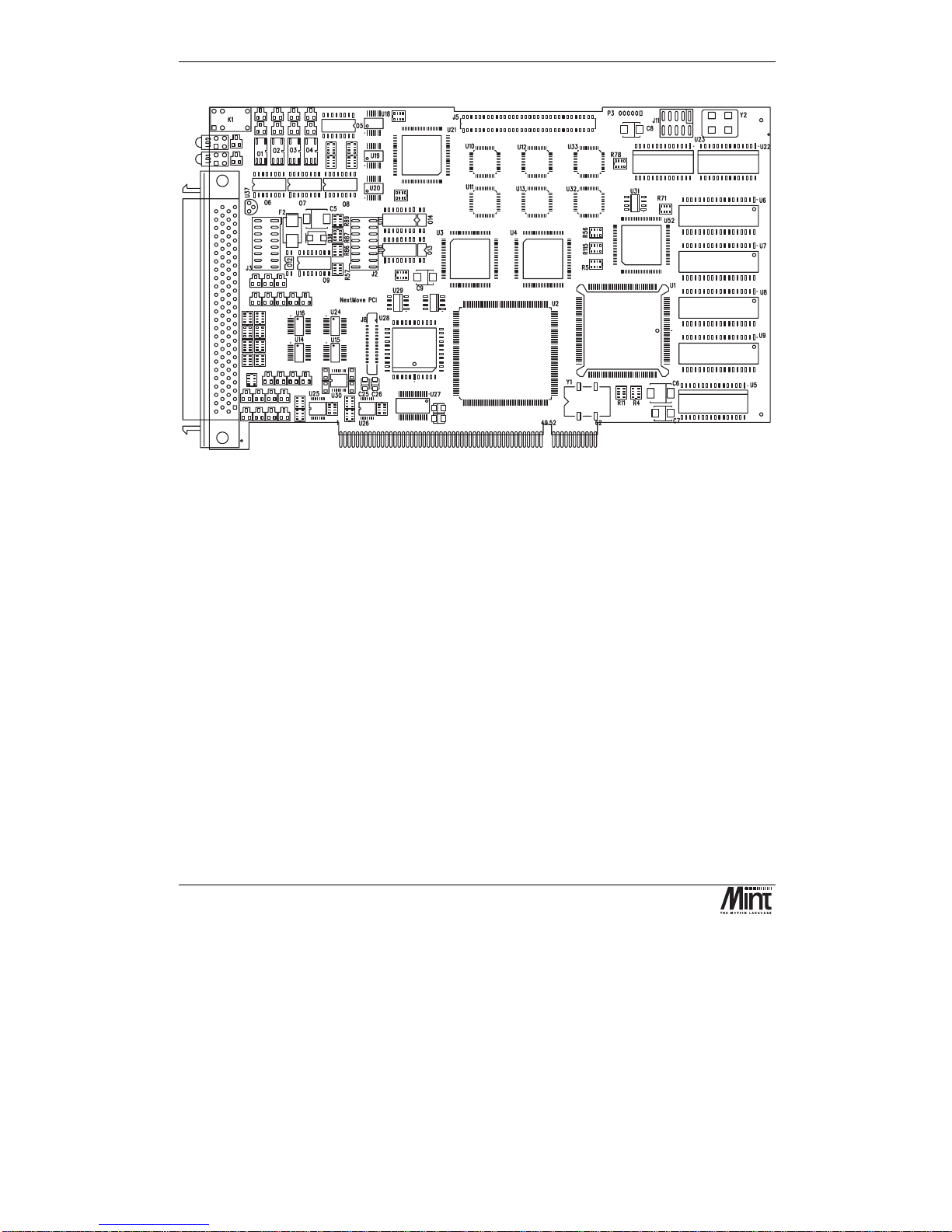
Figure 3-1: NextMove PCI Assembly
3.1 Operating Environment
The safe operation of this equipment depends upon its use in the appropriate environment:
•
At an altitude of
≤
2000m (6560ft) above sea level
•
In an ambient temperature of 0
°
C to 40°C (32°F to 104°F)
•
In relative humidity levels of 80% for temperatures up to 31
°
C (87°F) decreasingly linearly
to 50% relative humidity at 40
°
C (104°F), non-condensing
•
The pollution degree according to IEC664 shall not exceed 2
•
Power is supplied to the board via the PC power supply bus
•
The atmosphere shall not contain flammable gases or vapors
•
There shall not be abnormal levels of nuclear radiation or X-rays
Hardware Guide
MN1277 04.2001
9
3.2 Connection to the PCB
All of the standard interfaces are brought out on the 100 pin D-type connector mounted on the metal
bracket. The PCB connector is an AMP787082-9. For the convenience of the user a kit consisting of
a cable assembly and a DIN rail mounting Breakout Unit is available. There are currently two types
of Breakout Unit available. The standard type uses single part connectors (Baldor part no. PCI003-
501). A unit with two part connectors (Baldor part no. PCI003-502) is also available. These are
described in Section 5.4.
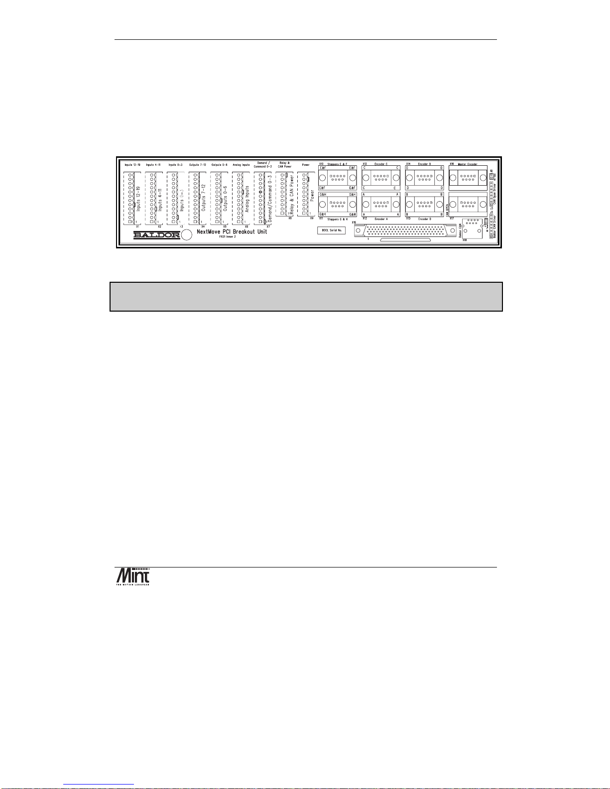
Figure 3-2: NextMove PCI Breakout Unit
For ease of transition from NextMove PC to NextMove PCI, a converter is available to allow
NextMove PC Breakout Unit to be used (contact factory).
See section 6.3 for connector details.
3.3 Digital I/O
There are a total of 20 general purpose digital inputs and 12 general purpose digital outputs. The
digital inputs are software configurable for any one of the following functions:
•
forward limit
(end of travel) input on any axis.
•
reverse limit
(end of travel) input on any axis.
•
home input
on any axis.
•
drive error
input on any axis.
•
stop input
(controlled) on any axis.
The inputs can be programmed such that any of the axes can share the same input if necessary.
The inputs are also programmable in software for edge triggered (positive and negative) and their
active level.
The digital outputs can be programmed as a
drive enable
output for any axis or
general error
output
. Again, axes can share the same output. The active level of the output is also software
programmable.
NextMove PCI Installation Manual
10
MN1277 04.2001
As well as the general purpose I/O, NextMove PCI also supports fast position latch inputs (IN0 to
IN3) and optionally, digital outputs for stepper control. The stepper outputs can be programmed in
software as general purpose outputs. The stepper outputs are discussed in section 3.5.
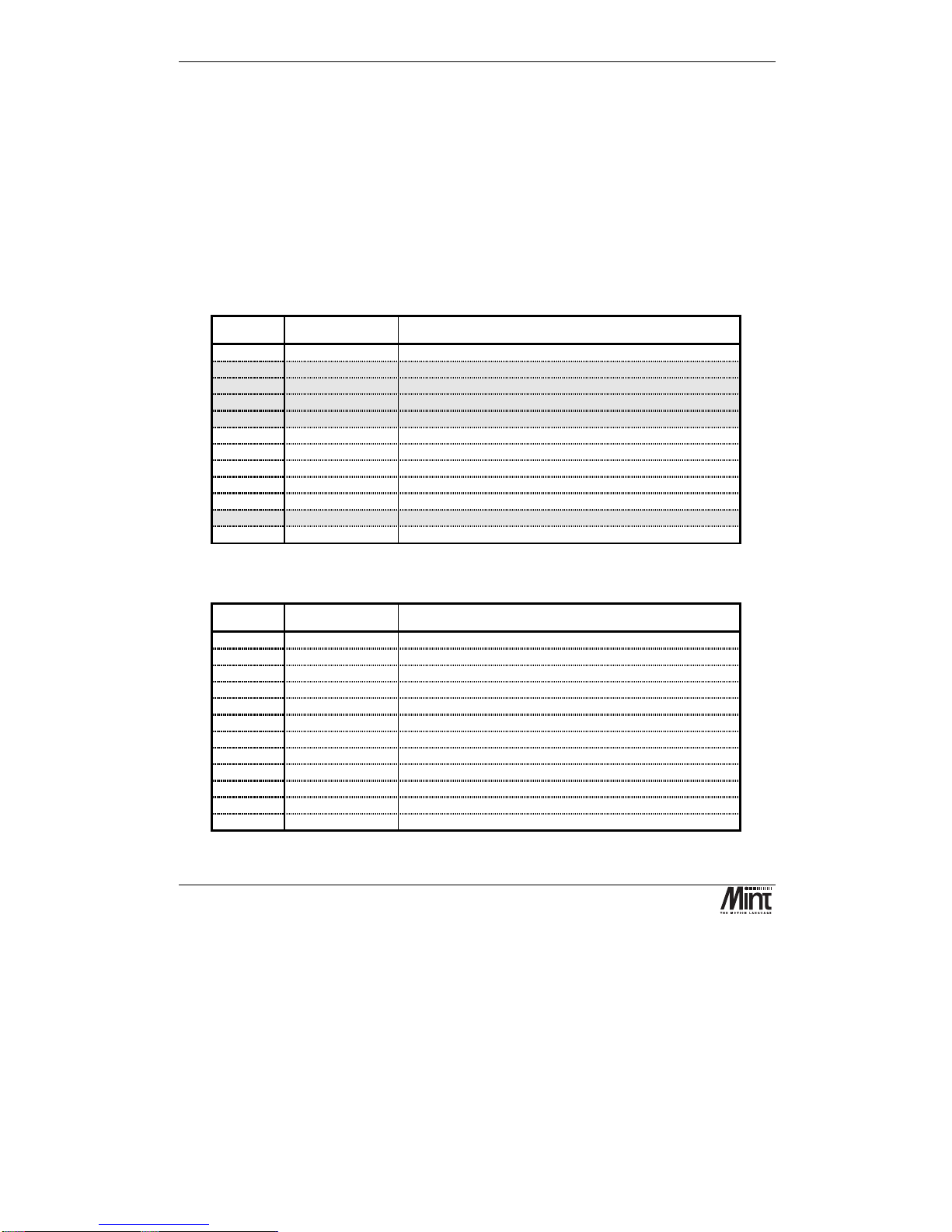
3.3.1 Standard Digital Inputs
There are sixteen optically isolated standard digital inputs arranged as two banks of 8. Each bank has
its own common rail that must be referred to system ground and cannot be left disconnected. Each
bank can have a separate supply or voltage level.
These inputs are available on connectors X1 and X2 on the NextMove PCI Breakout Unit.
X2: Digital Inputs 4 to 11
Pin Signal Function
1
Chassis
Shield connection
2
DIG_IN_4
Digital input 4 (referenced to Common0-7)
3
DIG_IN_5
Digital input 5 (referenced to Common0-7)
4
DIG_IN_6
Digital input 6 (referenced to Common0-7)
5
DIG_IN_7
Digital input 7 (referenced to Common0-7)
6
DIG_IN_8
Digital input 8 (referenced to Common8-19)
7
DIG_IN_9
Digital input 9 (referenced to Common8-19)
8
DIG_IN_10
Digital input 10 (referenced to Common8-19)
9
DIG_IN_11
Digital input 11 (referenced to Common8-19)
10
Chassis
Shield connection
11
Common0-7
Common for inputs 0-7
12
Common8-19
Common for inputs 8-19
X1: Digital Inputs 12 to 19
Pin Signal Function
1
Chassis
Shield connection
2
DIG_IN_12
Digital input 12 (referenced to Common8-19)
3
DIG_IN_13
Digital input 13 (referenced to Common8-19)
4
DIG_IN_14
Digital input 14 (referenced to Common8-19)
5
DIG_IN_15
Digital input 15 (referenced to Common8-19)
6
DIG_IN_16
Digital input 16 (referenced to Common8-19)
7
DIG_IN_17
Digital input 17 (referenced to Common8-19)
8
DIG_IN_18
Digital input 18 (referenced to Common8-19)
9
DIG_IN_19
Digital input 19 (referenced to Common8-19)
10
Chassis
Shield connection
11
n/c
Not connected
12
Common8-19
Common for inputs 8-19
Hardware Guide
MN1277 04.2001
11
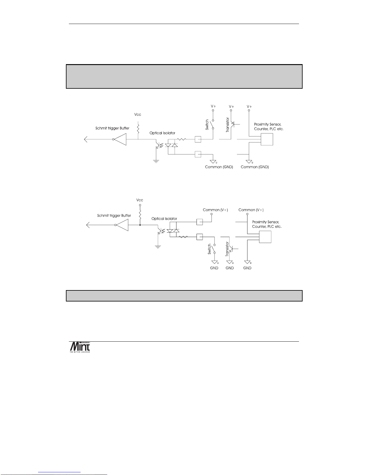
The digital inputs use ac opto-isolators. The switching level is 12 to 24V (supplied by the user). If
the driving signal switches high with reference to a low ground, the driving signal ground should be
connected to the input common. If the driving signal switches low with reference to a driving signal
supply rail, the driving supply rail should be connected to the input common.
When using the NextMove PC Breakout Unit and converter board (OPT025-506) the two
banks must use USR-V+ and USR-GND. Jumpers on the converter board select which voltage
is connected to the common rails.
Figure 3-3 shows a digital input connected to high-side (PNP) driving signals.
Figure 3-3:Digital Inputs, PNP configuration
Figure 3-4 shows a digital input connected to low-side (NPN) driving signals.
Figure 3-4: Digital Inputs, NPN Configuration
Note: Sustained voltages above 28V will damage the inputs.
The inputs are conditioned using low pass RC filters and Schmitt trigger buffers. An input pulse
must have a duration of at least 1ms (one software scan) to guarantee acceptance by the application
program when configured as edge triggered.
As with all good wiring practice, the use of screened cable is recommended.
NextMove PCI Installation Manual
12
MN1277 04.2001
Associated Mint keywords are:
#INx, INPUTACTIVELEVEL, IN, INx, INPUTMODE, INPUTNEGTRIGGER,
INPUTPOSTRIGGER, INSTATE
3.3.2 Fast Position Interrupts: Digital Inputs 0 to 3
Digital inputs
DIG_IN_0
to
DIG_IN_3
can be used as high speed position latches.
The inputs are available on connector X3 on the NextMove PCI Breakout Unit.
Pin Signal Function
1
DIG_IN_0
Digital input 0
2
Common0-7
Return for inputs 0-7
3
Chassis
Shield connection
4
DIG_IN_1
Digital input 1
5
Common0-7
Return for inputs 0-7
6
Chassis
Shield connection
7
DIG_IN_2
Digital input 2
8
Common0-7
Return for inputs 0-7
9
Chassis
Shield connection
10
DIG_IN_3
Digital input 3
11
Common0-7
Return for inputs 0-7
12
Chassis
Shield connection
Digital inputs 0 to 3 are sensitive to noise. The use of screened twisted pair cabling is recommended.
The fast position inputs are routed through a programmable cross point switch which allows any
input to cause the position of any combination of axes to be latched within 1µs - a feature essential
in high speed print registration applications. When triggered, the position is captured and a user
interrupt can be triggered to handle this event.
See section ‘Fast Position Latch’ in the ‘Mint v4 Programming Guide’ for more details.
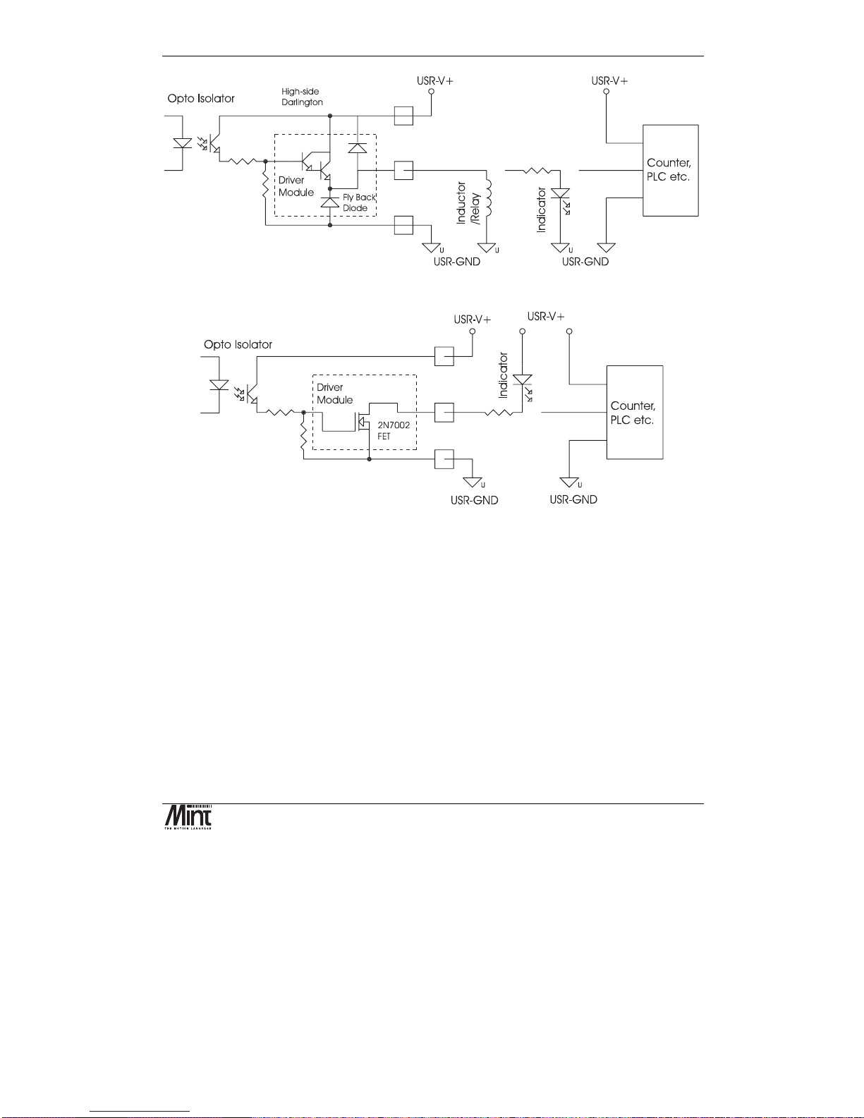
3.3.3 Digital Outputs
There are twelve opto-isolated digital outputs driven via a module fitted to NextMove PCI. Two
modules types are available:
Current sourcing, ‘PNP’ Darlington with overcurrent and short circuit protection (fitted as standard).
Current sinking, ‘NPN’, open drain N-channel MOSFET.
Hardware Guide
MN1277 04.2001
13
Figure 3-5: Digital Outputs with Current Sourcing Module
Figure 3-6: Digital Outputs with Current Sinking Module
The outputs are available on connectors X4 and X5 on the NextMove PCI Breakout Unit.

NextMove PCI Installation Manual
14
MN1277 04.2001
X5: Digital Outputs 0-5
Pin Signal Function
1
Chassis
Shield connection
2
DIG_OUT_0
Digital output 0
3
DIG_OUT_1
Digital output 1
4
DIG_OUT_2
Digital output 2
5
DIG_OUT_3
Digital output 3
6
DIG_OUT_4
Digital output 4
7
DIG_OUT_5
Digital output 5
8
n/c
Not connected
9
n/c
Not connected
10
Chassis
Shield connection
11
USR-V+
∗∗∗∗
Output power supply power
12
USR-GND
Output power supply ground
X4: Digital Outputs 6-11
Pin Signal Function
1
Chassis
Shield connection
2
DIG_OUT_6
Digital output 6
3
DIG_OUT_7
Digital output 7
4
DIG_OUT_8
Digital output 8
5
DIG_OUT_9
Digital output 9
6
DIG_OUT_10
Digital output 10
7
DIG_OUT_11
Digital output 11
8
n/c
Not connected
9
n/c
Not connected
10
Chassis
Shield connection
11
USR-V+
∗∗∗∗
Output power supply power
12
USR-GND
Output power supply ground
Note that USR-GND must be tied to system ground - it must not be left disconnected. When using
current sourcing outputs, the user must supply 12-24V DC between USR-V+ and USR-GND.
The current sink / source capability of the NPN and PNP outputs respectively is 50mA.
As with all good wiring practice, the use of screened cable is recommended.
Associated Mint keywords are:
OUTPUTACTIVELEVEL, OUT, OUTx
∗
This power must be supplied externally
Hardware Guide
MN1277 04.2001
15
3.4 Analog I/O
3.4.1 Analog Inputs
Four 12-bit resolution analog inputs are provided. The inputs are available on connector X6 on the
NextMove PCI Breakout Unit.
X6: Analog Inputs
Pin Signal Function
1
AGND
Analog ground
2
AIN_0+
Analog input 0 positive input
3
AIN_0-
Analog input 0 negative input
6
Chassis
Shield connection
1
AGND
Analog ground
4
AIN_1+
Analog input 1 positive input
5
AIN_1-
Analog input 1 negative input
6
Chassis
Shield connection
7
AGND
Analog ground
8
AIN_2+
Analog input 2 positive input
9
AIN_2-
Analog input 2 negative input
12
Chassis
Shield connection
7
AGND
Analog ground
10
AIN_3+
Analog input 3 positive input
11
AIN_3-
Analog input 3 negative input
12
Chassis
Shield connection
Shielded twisted pairs should be used and connected as shown. The shield connection should be
made at one end only. If the source of the signal is already grounded there is no need to connect
AGND (shown dotted).
The analog inputs pass through a differential buffer and second order Butterworth filter with a 1kHz
cut-off frequency. Both the filtered and unfiltered signals are converted using a multiplexed 12-bit
ADC, which has four software-selectable input voltage ranges: 0-5V, ±5V, 0-10V and ±10V.
The analog inputs are sampled by Mint at a rate of 2.5kHz.

NextMove PCI Installation Manual
16
MN1277 04.2001
Figure 3-7: Analog Buffer and Range Selection
Differential Mode:
The analog inputs are all true differential which means that the signal is measured relative to a
reference rather than the controller ground. The differential mode makes the system more immune to
common mode noise picked up in the cabling.
Figure 3-8: Analog Input, Differential Connection
Associated Mint keywords are:
ADCMODE, ADC
3.4.2 Analog Outputs (Drive Command)
There are four 14bit resolution analog outputs. The outputs are available on connector X7 on the
NextMove PCI Breakout Unit. By default Mint™ and the Mint™ Motion Library use the analog
outputs to control servo drives. Outputs 0 to 3 correspond to axes 0 to 3 respectively.

Hardware Guide
MN1277 04.2001
17
X7: Drive Signals (X7)
Pin Signal Function
1
DEMAND_0
Demand/command signal for axis 0
2
AGND
Analog ground
3
Chassis
Shield connection
4
DEMAND_1
Demand/command signal for axis 1
5
AGND
Analog ground
6
Chassis
Shield connection
7
DEMAND_2
Demand/command signal for axis 2
8
AGND
Analog ground
9
Chassis
Shield connection
10
DEMAND_3
Demand/command signal for axis 3
11
AGND
Analog ground
12
Chassis
Shield connection
Demand signals are outputs to the servo amplifiers. Shielded twisted pairs should be used and
connected as shown. The shield connection should be made at one end only.
The outputs have a range of ±10V (1.22mV per bit).
Outputs 0 to 3 are inverted and buffered by op-amps, and may be used to drive loads of
≥
10kΩ. The
outputs are referenced to PC system ground. DAC channels 4-7 are summed with the first three
outputs with 1/16
th
of the gain i.e. 1/16th of the DAC channel 4 output is added to the DAC channel 0
output, and so on. DAC channels 4 – 7 can therefore be used to trim channels 0 - 3 (trim range
±0.625V).
The analog output buffer circuit is shown below.
Figure 3-9: Analog Output Buffer
Associated Mint keywords are:
DACLIMITMAX, DAC, DACMODE, DACOFFSET

NextMove PCI Installation Manual
18
MN1277 04.2001
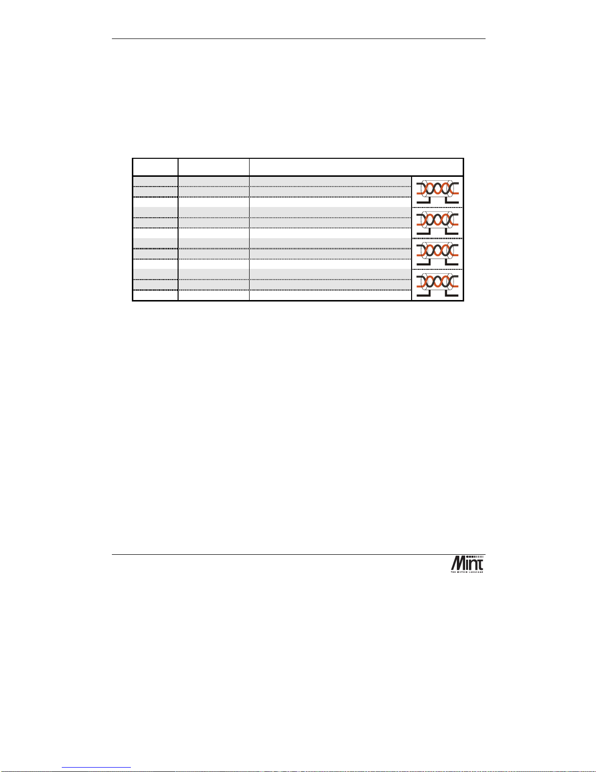
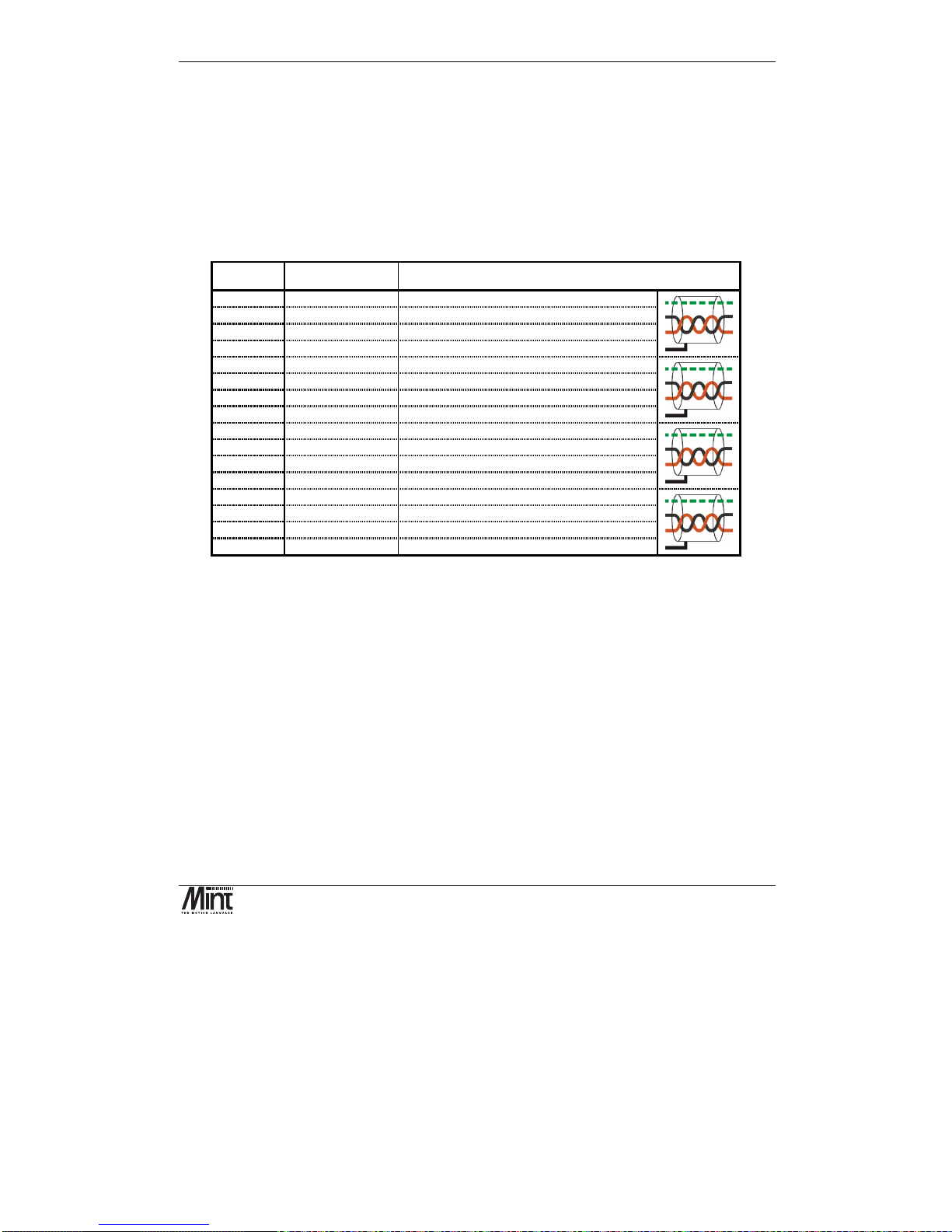
3.5 Encoder Interface
Up to five incremental encoders may be connected to NextMove PCI. The signals are brought out
onto the NextMove PCI Breakout Unit via signals X12, X13, X14, X15 and X16. These are 9-pin
D-type female sockets. The shell of the connector is connected to chassis. When possible, the use of
individually screened twisted pair cable is recommended.
Figure 3-10: Encoder Connector
Pin Signal Function Cabling
1
Encoder V+
1
Power to the encoder
7
gnd
Power and signal ground
5
chA
Channel A true signal
9
!chA
Channel A complement signal
8
chB
Channel B true signal
3
!chB
Channel B complement signal
2
index
Index true signal (channel I or Z or C)
6
!index
Index complement signal (channel I or Z or C)
4
chassis
Chassis connection
Shell
chassis
Screen
The encoders must provide either complementary TTL or differential line drive (RS422/RS485)
signals to operate with NextMove PCI. The input circuit uses MAX3095 differential line receivers
with a pull ups and terminators. Each encoder channel has inputs A, B and Index.
1
The encoder power rail on X9 must be connected to VCC or supplied externally
Hardware Guide
MN1277 04.2001
19
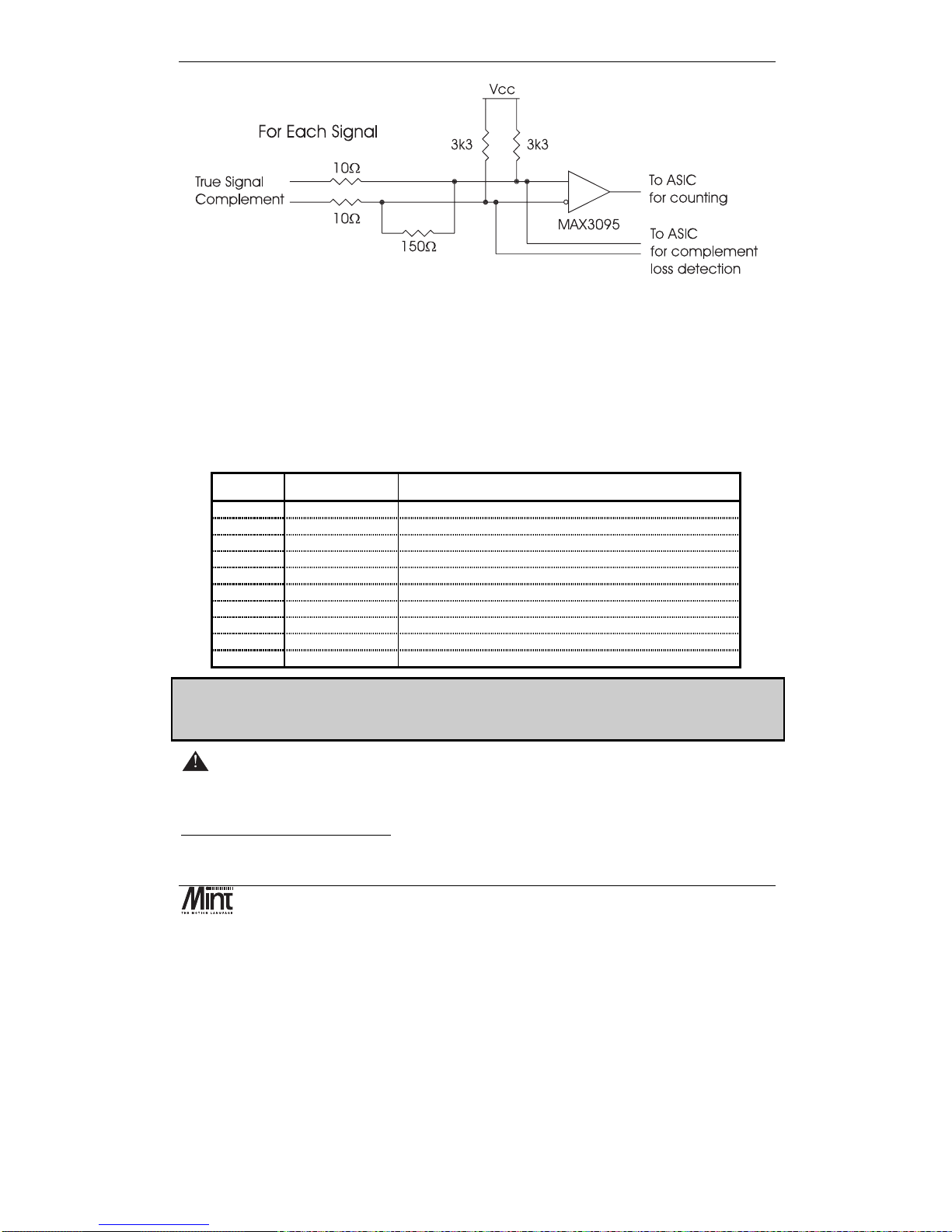
Figure 3-11: Encoder Line Receiver Interface
The maximum input frequency of the encoder input is 7.5 million quadrature counts per second, one
count per edge. This equates to a maximum frequency for the A and B signals of 1.87MHz.
Within Mint, ‘complement loss detection’ is highlighted as an ‘encoder transition warning’ within
the AXISWARNING keyword. It must be enabled with the AXISWARNINGDISABLE keyword.
Associated Mint keywords are:
ENCODER, ENCODERSCALE, ENCODERVEL, ENCODERWRAP, POS, SCALE, VEL
X9: Encoder Power
Pin Signal Function
1
Vcc
5V power connection (from the PC)
2
Vcc
5V power connection (from the PC)
3
Encoder V+
1
Power to the encoder connectors (normally +5V)
4
Encoder V+
1
Power to the encoder connectors (normally +5V)
5
GND
Digital ground (from the PC)
6
GND
Digital ground (from the PC)
7
USR-V+
2
Output power supply
8
USR-V+
2
Output power supply
9
USR-GND
Output power supply ground
10
USR-GND
Output power supply ground
Note: The encoder power can be linked to Vcc to supply the encoders with +5V, provided that
the total current consumption of the encoders does not exceed 500mA. For externally powered
encoders, the maximum is 30V provided total current consumption does not exceed 3A.
Warning – Encoder power must be connected before switching on.
If the encoders are not powered then there will be no position feedback which could cause violent
motion of the motor shaft if the system is enabled.
1
Encoder V+ must be connected to VCC or supplied externally
2
USR-V+ must be supplied externally
NextMove PCI Installation Manual
20
MN1277 04.2001
The encoder connectors are powered from pins 3 and 4 of the power connector X9. This voltage is
with respect to digital ground. This connection scheme is to allow correct powering of the encoders
where the required voltage is not 5V and/or the total current exceeds 500mA. For encoders
requiring 5V power at a total current, for all encoders, of 500mA or less, the encoder V+ rail may be
connected to V
CC
by linking pins 2 (VCC) and 3 (Encoder V+) of X9. A link is fitted in this position
at the factory.
Baldor CAN
Note:- Replacing issue 1 units
If replacing issue 1 breakout units, connections to pins 3, 4, 5 and 6 of the issue 1 unit power
connector(J10) must be connected to pins 5 and 6 only of the issue 2 unit power connector (X9).
3.6 Relay
A single pole change-over relay is included on the card to provide a volt-free contact for system
enabling or general use. The relay signals are available on the NextMove PCI Breakout Unit via
connector X8.
X8: Relay and CAN Power
Pin Signal Function
1
CAN-V+ 1
Power input for CAN 1 network (
CAN
open
). (12-24V)
2
CAN-GND 1
Ground for CAN 1 network (
CAN
open
)
3
CAN-V+ 2
Power input for CAN 2 network (Baldor CAN) (12-24V)
4
CAN-GND 2
Ground for CAN 2 network (Baldor CAN)
5
Relay-NC
Normally closed relay connection
6
Relay-NO
Normally open relay connection
7
Relay-COM
Common relay connection
8
USR-V+
2
Output power supply power
9
USR-GND
Output power supply ground
10
Chassis
Shield connection
Only isolated CAN channels require 24V to power to opto-isolation. Non isolated CAN
channels must not be powered.
The relay pins are isolated from any internal circuits on the NextMove PCI.

Hardware Guide
MN1277 04.2001
21
The relay is controlled by a latch, which is cleared during reset of NextMove PCI. Reset occurs on
power-down, watchdog error or under control of the host PC. The relay is energized under software
control. The relay is the default global error output channel.
Due to the track rating on the PCB, the relay is limited to a rating of 150mA at 24V DC. The
relay should be used for voltage free signal switching and should not be used for power.
Associated Mint keywords are:
RELAY, DRIVEENABLEOUTPUT, GLOBALERROROUTPUT
3.7 Stepper Drive Outputs
Eight stepper motor control outputs are available via connectors X10 and X11.
X10/X11: Stepper Drive Outputs
Figure 3-12: Stepper Output Connectors
The stepper drive outputs can operate at up to 3MHz. The signals from the controller are at TTL
levels and is converted to differential drive on a module mounted on the Breakout Unit. The
differential connections are brought out on 9 pin D-type connectors to allow 360° shielding when
using high step rates. Two axes are brought out on to each connector. The outputs can be connected
directly to drives with single ended logic inputs by connecting the compliment of the differential
signal to the drive ground.
Signal Pin Nos. Function Cabling
Step n
1,5 Step signal True
!Step n
6,9 Step signal Complement
Dir n
2,4 Direction signal True
!Dir n
7,8 Direction signal Complement
GND
3 Signal ground
chassis
Shell Screen

NextMove PCI Installation Manual
22
MN1277 04.2001
The outputs may be programmed in software for the following functions:
•
Step and direction for driving stepper motor drives.
•
Digital outputs for general purpose use. See the STEPPERIO keyword for details.
The outputs are all CMOS level signals and are referred to system ground.
3.8 CAN Bus
CAN (Controller Area Network) is a 1Mb/s local area network. Two transceivers for the CAN are
fitted to NextMove PCI. Access to both channels it is made via a 10 pin 2mm pin header
J11
. The
connections are as follows:
Figure 3-13: NextMove PCI CAN Header Location
Pin No. Signal
1 CAN2 RX0 (from IC)
2 to Breakout Unit
3 CAN2 TX0 (from IC)
4 to Breakout Unit
5 CAN1 RX0 (from IC)
6 to Breakout Unit
7 CAN1 TX0 (from IC)
8 to Breakout Unit
9 GND
10 +5V

Hardware Guide
MN1277 04.2001
23
Note: the signals on this connector are referenced to the PC host, there is no isolation. As standard,
jumper links are present linking pin pairs 1 and 2, 3 and 4, 5 and 6, 7 and 8. These jumpers route the
CAN signals to the Breakout Unit.
Pins 9 and 10 should NEVER be connected to together.
Removing the jumpers allows connection to a bulkhead mounted drive circuit and a connector or
connector pair of the required type in the next PCI slot plate. These can be RJ45 for connection to
other Baldor CAN nodes or 9 pin ‘D’ connectors for connection to other networks such as
CAN
open
. A CAN bracket card is available which is suitable if the customer is intending to only
use NextMove PCI as a CAN master, since this no longer requires the Breakout Unit.
CAN connections on the Breakout Unit are one RJ45 connector for CAN2 and a 9 pin D-type for
CAN1; used for connection to
CAN
open
networks. If NextMove PCI is at the end of either network
a termination resistor must be connected by fitting the termination jumper on the Breakout Unit.
A range of CAN based I/O expansion modules is available for NextMove PCI. See section 5.7 for
further details.
A very low error rate of CAN communication can only be achieved with a suitable wiring scheme.
The following points should be observed:
1. CAN must be connected via twisted pair cabling. The connection arrangement is normally
a simple multi-point drop. The CAN cables should have a characteristic impedance of
120Ω and a delay of 5ns/m. Other characteristics depend upon the length of the cabling:
Cable length Max bit rate
Non Isolated
Max bit rate
Isolated
Specific
resistance
Conductor area
0-40m (0-157ft) 1 Mbit/s 500 kbit/s
70m
Ω
0.25-0.34mm
2
40m-300m
(157ft-1180ft)
200 kbit/s 100 kbit/s
<
60m
Ω
0.34-0.60 mm
2
300m-600m
(1180-2362ft)
100 kbit/s 50 kbit/s
<
40m
Ω
0.50-0.60 mm
2
600m-1000m
(2362ft-3937)
50 kbit/s 25 kbit/s
<
26m
Ω
0.75-0.80 mm
2
2. Terminators should be fitted at each end of the network only.
3. To reduce RF emissions, and more importantly to provide immunity to conducted
interference, shielded twisted pair cabling should be used. If two CAN channels are
bundled in a cable then each requires a twisted pair.
4. The 0V rails of all of the nodes on the network must be tied together through the CAN
cabling. This ensures that the CAN signal levels transmitted by a NextMove PCI or CAN
peripheral devices are within the common mode range of the receiver circuitry of other
nodes on the network.

NextMove PCI Installation Manual
24
MN1277 04.2001
CAN cables are available. See the section 5.7 for details on CAN accessories.
On the Breakout Unit, CAN is available on connectors X17 and X18.
Figure 3-14: CAN Connectors
Where an isolated transceiver module is used a supply of 12-24V, 60mA is required between CANV+ and CAN-GND. Non isolated module should not be powered.
Signal Function D-type Pin RJ-45 Pin Cabling
can+
CAN data signal 7 1
can-
CAN data signal 2 2
can V+
Power to the CAN nodes 9 5
gnd
Signal ground 3 4
chassis
Screen pin 1 -
NC No connection 4,5,6,8 3,6,7,8
chassis
Screen Shell Shell
3.9 Reset State
During PC power-up, NextMove PCI is held in reset (a safe non-operational state). It will also go
into reset if the 5V supply drops below approximately 4.75V in order to prevent any uncontrolled
operation of any of the integrated circuits during power down.
When NextMove PCI is in reset for any reason, most of the controlled interfaces fall into known
states as detailed in the following sections.
It is also possible for NextMove PCI to be in a state known as software reset. This is a safe
operational state where only the bootloader firmware present on NextMove PCI is running.
Hardware and software reset states should not be confused with the Mint keyword RESET which is
used to clear axis errors.
Communications

Hardware Guide
MN1277 04.2001
25
At power up the CAN controllers will be held in reset and will have no effect on the CAN buses. If a
reset occurs during the transmission of a message CAN errors are likely to occur.
Dual port RAM will contain no information at power up but will be accessible by the PC. A reset
during operation will cause the DPR to stay in its current state.
Digital Outputs
All of the digital outputs are inactive on power up regardless of their polarity. They will return to the
inactive state whenever reset occurs.
Analog Outputs
All analog outputs are set to 0V by hardware during power-up and will return to 0V on a reset.
Stepper/Encoder ASICs
The stepper/encoder ASICs will not generate stepper pulses or register any encoder input during
reset. Position will be set to zero, i.e. if the unit goes into reset all position data will be lost.
3.10 LEDs
There are four bicolour LED’s on NextMove PCI. Two LEDs, S1 and S2, are status indicators and
two, C1 and C2, are CAN traffic indicators. The LED’s can be
red
or
green
and may be
steady
or
flashing
. These states are shown in the following table for the status LED’s:
Figure 3-15: Status and CAN indicator LEDs
State LED Status
No power. All off
In hardware reset. All red
In software reset with no errors. Cycling green
In software reset with POST1 errors. Cycling red
Application running successfully. S1 flashing green (slow)
Application running with initialization error. S1 flashing red (slow)
Asynchronous error (for example: limit switch tripped). S2 flashing red (fast)
Miscellaneous error (for example: output driver not powered). S2 flashing green (fast)
Reception of CAN message on CAN2 C2 flashing
1
POST = power on self test

NextMove PCI Installation Manual
26
MN1277 04.2001
Updating controller firmware All flashing green (slow)
POST executing (after reset command) All red, go off sequentially
(C1,S1,S2,C2)
There are two bicolour LED’s on the NextMove PCI Expansion card. The LED’s can be
red
or
green
and may be
steady
or
flashing
. These states are shown in the following table:
S1
S2
S1
S2
Figure 3-16: Status and CAN indicator LEDs
Expansion LED Status State
All off No power or not used. Check main card LEDs.
All red In hardware reset.
Alternately flashing green In software reset with no errors.
Alternately flashing red In software reset with POST2 errors.
S1 flashing green (slow) Application running successfully.
S1 flashing red (slow) Application running with initialization error.
S2 flashing red (fast) Asynchronous error (for example: limit switch tripped).
S2 flashing green (fast) Miscellaneous error (for example: output driver not powered).
3.11 NextMove PCI Expansion Card
A 64-pin socket on the top edge of NextMove PCI provides a 16-bit expansion bus. The Expansion
Card has the same set of I/O as the main board (except for CAN) and uses the same Breakout Unit
and cabling. NextMove PCI can directly support one or two Expansion Cards. Connection to the
cards is made through a bridging PCB (the
Expansion Interconnect
) that plugs across the top of the
main and Expansion Cards.
2
POST = power on self test

Hardware Guide
MN1277 04.2001
27
Figure 3-17: NextMove PCI Expansion Card
Notes:
The Expansion Interconnect is polarized to prevent mis-insertion. If two Expansion Cards are used
then the Dual Interconnect board is needed. It highly advisable to exert a retaining force on the
interconnect board, for example with a metal bracket and non-conductive padding. See section 5.2
for details on Expansion Card accessories.
The NextMove PCI Expansion card is available in 4 or 8 axis variants, providing an additional 4 or 8
servo / stepper axes. Each expansion card also adds 20 digital inputs, 12 digital outputs, 4 analog
inputs, 4 analog outputs (drive command) and a relay.
The following sections of the Hardware Guide chapter are applicable to the expansion card as well
as the main card:
3.2 Connection to the PCB
3.3 Digital I/O
3.4 Analog I/O
3.5 Encoder Interface
3.6 Relay
3.7 Stepper Drive Outputs
3.13 NextMove PCI Breakout Unit

NextMove PCI Installation Manual
28
MN1277 04.2001
3.12 Miscellaneous
3.12.1 Emulator Connection
An 11-pin footprint on the rear of the card marked ‘ICE’ provides access to the processor for
boundary scan emulation. To connect the Texas Instruments emulator pod, a two row 12 pin 0.1”
pitch surface mount pin header with pin 8 missing must be fitted. The connections are those
specified by Texas Instruments. See the ‘Mint v4 Embedded Programming Guide’ for details on
emulator based system debugging.
3.12.2 System Watchdog
The system watchdog is a hardware protection method so that in the event of a firmware or ‘C’
program malfunction, the controller is put into software reset. It may be disabled during low level
code development and debugging. After reset it is possible to determine that the reset was caused by
the system watchdog and take different action from normal. See the ‘Mint v4 Embedded
Programming Guide’ and the ‘Mint v4 PC Programming Guide’ for details.
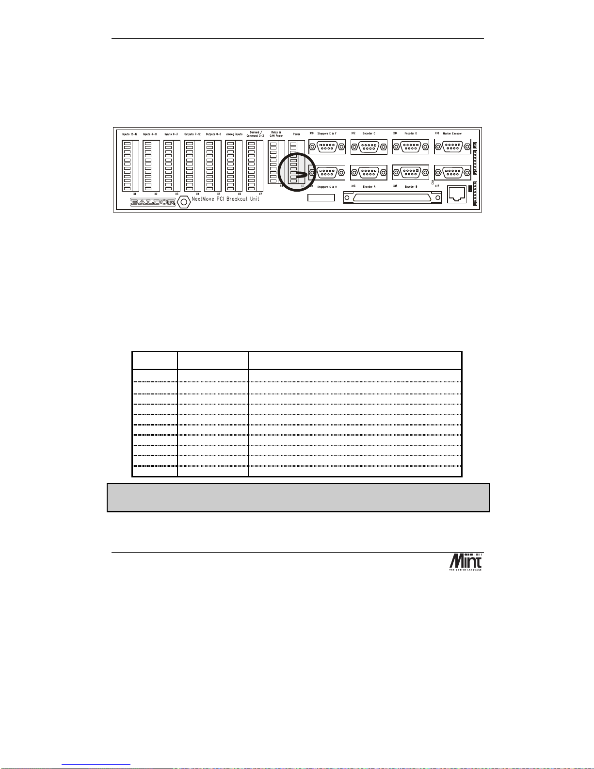
3.13 NextMove PCI Breakout Unit
Two Breakout Units are available for use with the NextMove PCI Expansion Card, one with single
part screw down terminals and the other with two part screw down terminals. The Breakout Unit is
approximately 292mm (11.50 inches) long by 70mm (2.76 inches) wide by 62 mm (2.45 inches)
high. The layout of the board is shown in Figure 3-18. It fits on to either a 35mm symmetric DIN
rail (EN 50 022, DIN 46277-3) or a G-profile rail (EN 50 035, DIN46277-1). The Breakout Unit
connects to NextMove PCI using the 100-Way cable.
Figure 3-18: NextMove PCI Breakout Unit Assembly
This section provides connection details for each connector. For further information, see the earlier
detailed sections on each functional block.

Hardware Guide
MN1277 04.2001
29
3.13.1 X1 - Inputs 12-19
Pin Signal Function
1
Chassis
Shield connection
2
DIG_IN_12
Digital input 12 (referenced to Common8-19)
3
DIG_IN_13
Digital input 13 (referenced to Common8-19)
4
DIG_IN_14
Digital input 14 (referenced to Common8-19)
5
DIG_IN_15
Digital input 15 (referenced to Common8-19)
6
DIG_IN_16
Digital input 16 (referenced to Common8-19)
7
DIG_IN_17
Digital input 17 (referenced to Common8-19)
8
DIG_IN_18
Digital input 18 (referenced to Common8-19)
9
DIG_IN_19
Digital input 19 (referenced to Common8-19)
10
Chassis
Shield connection
11
n/c
Not Connected
12
Common8-19
Common for Inputs 8-19
3.13.2 X2 - Inputs 4-11
Pin Signal Function
1
Chassis
Shield connection
2
DIG_IN_4
Digital input 4 (referenced to Common0-7)
3
DIG_IN_5
Digital input 5 (referenced to Common0-7)
4
DIG_IN_6
Digital input 6 (referenced to Common0-7)
5
DIG_IN_7
Digital input 7 (referenced to Common0-7)
6
DIG_IN_8
Digital input 8 (referenced to Common8-19)
7
DIG_IN_9
Digital input 9 (referenced to Common8-19)
8
DIG_IN_10
Digital input 10 (referenced to Common8-19)
9
DIG_IN_11
Digital input 11 (referenced to Common8-19)
10
Chassis
Shield connection
11
Common0-7
Common for Inputs 0-7
12
Common8-19
Common for Inputs 8-19

NextMove PCI Installation Manual
30
MN1277 04.2001
3.13.3 X3 - High Speed Inputs
Pin Signal Function
1
DIG_IN_0
Digital input 0
2
Common0-7
Reference for inputs 0-7
3
Chassis
Shield connection
4
DIG_IN_1
Digital input 1
5
Common0-7
Reference for inputs 0-7
6
Chassis
Shield connection
7
DIG_IN_2
Digital input 2
8
Common0-7
Reference for inputs 0-7
9
Chassis
Shield connection
10
DIG_IN_3
Digital input 3
11
Common0-7
Reference for inputs 0-7
12
Chassis
Shield connection
3.13.4 X4 - Outputs 6-11
Pin Signal Function
1
Chassis
Shield connection
2
DIG_OUT_6
Digital output 6
3
DIG_OUT_7
Digital output 7
4
DIG_OUT_8
Digital output 8
5
DIG_OUT_9
Digital output 9
6
DIG_OUT_10
Digital output 10
7
DIG_OUT_11
Digital output 11
8
n/c
Not connected
9
n/c
Not connected
10
Chassis
Shield connection
11
USR-V+
∗∗∗∗
Output power supply power
12
USR-GND
Output power supply ground

Hardware Guide
MN1277 04.2001
31
3.13.5 X5 - Outputs 0-5
Pin Signal Function
1
Chassis
Shield connection
2
DIG_OUT_0
Digital output 0
3
DIG_OUT_1
Digital output 1
4
DIG_OUT_2
Digital output 2
5
DIG_OUT_3
Digital output 3
6
DIG_OUT_4
Digital output 4
7
DIG_OUT_5
Digital output 5
8
n/c
Not connected
9
n/c
Not connected
10
Chassis
Shield connection
11
USR-V+
∗∗∗∗
Output power supply power
12
USR-GND
Output power supply ground
3.13.6 X6 - Analog Inputs
Pin Signal Function
1
AGND
Analog Ground
2
AIN_0+
Analog input 0 positive input
3
AIN_0-
Analog input 0 negative input
6
Chassis
Shield connection
1
AGND
Analog Ground
4
AIN_1+
Analog input 1 positive input
5
AIN_1-
Analog input 1 negative input
6
Chassis
Shield connection
7
AGND
Analog Ground
8
AIN_2+
Analog input 2 positive input
9
AIN_2-
Analog input 2 negative input
12
Chassis
Shield connection
7
AGND
Analog Ground
10
AIN_3+
Analog input 3 positive input
11
AIN_3-
Analog input 3 negative input
12
Chassis
Shield connection
∗
This power must be supplied externally

NextMove PCI Installation Manual
32
MN1277 04.2001
3.13.7 X7 – Command Signals
Pin Signal Function
1
DEMAND_0
Command signal for axis 0
2
AGND
Analog ground
3
Chassis
Shield connection
4
DEMAND_1
Command signal for axis 1
5
AGND
Analog ground
6
Chassis
Shield connection
7
DEMAND_2
Command signal for axis 2
8
AGND
Analog ground
9
Chassis
Shield connection
10
DEMAND_3
Command signal for axis 3
11
AGND
Analog ground
12
Chassis
Shield connection
3.13.8 X8 - PSU connections
Pin Signal Function
1
CAN-V+ 1
Power input for CAN 1 network (
CAN
open
)
2
CAN-GND 1
Ground for CAN 1 network (
CAN
open
)
3
CAN-V+ 2
Power input for CAN 2 network (Baldor CAN)
4
CAN-GND 2
Ground for CAN 2 network (Baldor CAN)
5
Relay-NC
Normally closed relay connection
6
Relay-NO
Normally open relay connection
7
Relay-COM
Common relay connection
8
USR-V+
2
Output power supply power
9
USR-GND
Output power supply ground
10
Chassis
Shield connection
2
USR-V+ must be supplied externally

Hardware Guide
MN1277 04.2001
33
3.13.9 X9 - Encoder Power
Pin Signal Function
1
Vcc
5V power connection (from the PC)
2
Vcc
5V power connection (from the PC)
3
Encoder V+
1
Power to the encoder connectors (normally +5V)
4
Encoder V+
1
Power to the encoder connectors (normally +5V)
5
GND
Digital ground (from the PC)
6
GND
Digital ground (from the PC)
7
USR-V+
2
Output power supply
8
USR-V+
2
Output power supply
9
USR-GND
Output power supply ground
10
USR-GND
Output power supply ground
3.13.10 X10, X11 - Steppers
Figure 3-19: Stepper D-types Connector
Signal Pin Nos. Function Cabling
Step n
1,5 Step signal true
!Step n
6,9 Step signal complement
Dir n
2,4 Direction signal true
!Dir n
7,8 Direction signal complement
GND
3 Signal ground
chassis
Shell screen
1
Encoder V+ must be connected to VCC or supplied externally
2
USR-V+ must be supplied externally

NextMove PCI Installation Manual
34
MN1277 04.2001
3.13.11 X12, X13, X14, X15, X16 - Encoders
Figure 3-20: Encoder Connector
Pin Signal Function Cabling
1
Encoder V+
∗∗∗∗
Power to the Encoder (not always 5V)
7
gnd
Power and signal ground
5
chA
Channel A true signal
9
!chA
Channel A complement signal
8
chB
Channel B true signal
3
!chB
Channel B complement signal
2
index
Index true signal (channel I or Z or C)
6
!index
Index complement signal (channel I or Z or C)
4
chassis
Chassis connection
Shell
chassis
Screen
∗
This power rail must be connected to VCC or supplied externally

Hardware Guide
MN1277 04.2001
35
3.13.12 X17, X18 - CAN
Figure 3-21: CAN Connectors
Signal Function D-type Pin RJ-45 Pin Cabling
can+
CAN data signal 7 1
can-
CAN data signal 2 2
can V+
Power to the CAN Nodes 9 5
gnd
Signal ground 3 4
chassis
Screen pin 1 -
NC No connection 4,5,6,8 3,6,7,8
chassis
Screen Shell Shell

NextMove PCI Installation Manual
36
MN1277 04.2001

Operation and Setup
MN1277 04.2001
37
4. Operation and Setup
4
This chapter is step by step guide to setting up a NextMove PCI servo and
stepper control system. Basic familiarity with PC’s and the Windows
environment is assumed.
Installing NextMove PCI into the PC.
Introduction to servo systems and tuning. Determining system gains and
fine-tuning.

NextMove PCI Installation Manual
38
MN1277 04.2001
4.1 Installing NextMove PCI
NextMove PCI can be installed into an AT style personal computer that has a free 7 inch PCI card
slot. The Baldor Motion Toolkit CD supports the following operating systems only: Windows 95,
Windows 98 and Windows NT version 4.
4.1.1 Placing the Card In the Computer
Before placing the card in the computer, carry out the following steps:
1. Exit any applications that are running and close all windows.
2. Turn off the power and unplug all power cords.
3. Remove the cover from your computers system unit.
4. Locate an unused PCI slot.
Note that before touching the card, be sure to discharge static electricity from hands by
touching a grounded metal surface, such as the screw on an electrical outlet’s plate cover.
Alternatively, wear an earth strap while handling the card.
5. Remove the cover from the slot, and save the screw for use later.
6. Discharge any static electricity from hands.
7. Remove the card from its protective wrapper. Do not to touch the gold contacts at the bottom of
the card.
8. Align the bottom of the card (gold contacts) with the slot and press the card firmly into the
socket. When correctly installed, the card locks into place.
9. Make sure that the top of the card is level (not slanted) and that the hole on top of the card’s
metal bracket lines up with the screw hole at the back of the slot.
10. Anchor the card in place using the screw removed earlier.
11. Replace the computer cover and screws.
12. Reconnect any cables and power cords that were disconnected or unplugged and turn on the
computer.
4.1.2 Installing Software
NextMove PCI is a plug and play device. Once the card has been inserted into the PC it will be
detected the next time the PC is turned on. This detection process varies depending on the operating
system running on the PC.

Operation and Setup
MN1277 04.2001
39
Windows 95/98/ME:
As Windows 95/98/ME starts it will display a dialog box indicating that it has detected the presence
of a new PCI card, the ‘Update Device Driver Wizard’. This utility will allow a device driver to be
selected for NextMove PCI.
Figure 4-1: Windows 95 ‘Update Device Driver Wizard’
Place the Baldor Motion Toolkit CD into the CDROM of the computer. Select ‘Next’ and then
manually specify the following directory which contains the device driver for NextMove PCI:
DRIVERS\NMPCI\WIN9x
Once the device driver has been selected Windows will continue to load.
Windows NT:
Under Windows NT there will be no indication that a new card has been installed. The device driver
for NextMove PCI will need to be installed from the Baldor Motion Toolkit. Place the Baldor
Motion Toolkit CD into the CDROM of the computer. The CD should auto-run and display the
‘Welcome to the Baldor Motion Toolkit’ page. If auto-run is disabled, browse the CD and double
click the file SETUP.HTM.

NextMove PCI Installation Manual
40
MN1277 04.2001
Select ‘NextMove PCI’ from the menu and select the ‘NextMove PCI NT Device Driver’ option on
the NextMove PCI page of the Baldor Motion Toolkit. Once the device driver has been installed it
will be necessary to restart your PC. This will load the device driver and enable communication with
NextMove PCI.
If upgrading your device driver from a previous release, you must uninstall the old device
driver first. To do this, select ‘NextMove PCI Device Driver’ from the ‘Add/Remove
Programs’ group in Windows Control Panel.
The driver can also be found in the following directory.
DRIVERS\NMPCI\WINNT
Windows 2000:
The Windows NT device driver can be used under Windows 2000.
After installing the NextMove PCI card, turn the PC on. Enter the BIOS and disable the ‘Plug and
Play’ option or select ‘Operating system is not plug and play compatible’. Exit the BIOS and let
Windows 2000 boot.
Once Windows 2000 has loaded it will enter the Hardware Wizard.
•
Select 'Search for a suitable device driver', hit 'Next'.
•
Un-check all search locations, hit 'Next'.
•
Select the 'Disable the device' option, hit 'Finish'.
Restart the PC, the hardware wizard should not re-appear.
The Windows NT device driver then needs to be installed from the Baldor Motion Toolkit CD.
Place the Baldor Motion Toolkit CD into the CDROM of the computer. The CD should auto-run and
display the ‘Welcome to the Baldor Motion Toolkit’ page. If auto-run is disabled, browse the CD
and double click the file SETUP.HTM. Using the Baldor Motion Toolkit install the NMPCI device
driver, either by using the HTML front end or directly from CD Drive\Mint v4\Installation\NT
NMPCI Device Driver.
The WinNT Device Driver works under Win2000, but the Device Manager may report a conflict and
display the device along with a ! symbol. This is only because the Device Driver is not native to
Win2000, and does not affect functionality.
4.2 Baldor Motion Toolkit CD
Place the Baldor Motion Toolkit CD in the CD drive of the PC. The CD will auto-run and display
the home page. If auto-run is disabled, browse the CD and double click the file ‘SETUP.HTM’.

Operation and Setup
MN1277 04.2001
41
Figure 4-2: Baldor Motion Toolkit - Home Page
Select the NextMove link and then select the ‘NextMove PCI’ option. This opens the page that
allows the various NextMove PCI related applications to be installed.
Figure 4-3: Baldor Motion Toolkit – NextMove PCI page

NextMove PCI Installation Manual
42
MN1277 04.2001
The
Mint WorkBench
is the IDE and user interface for communicating with a Mint controller.
Installing the Mint WorkBench will also install firmware (NMPCI.OUT) for NextMove PCI. The
Mint Configuration Tool
is a rapid getting started and configuration utility designed for use with a
number of Mint v4 controllers. The rest of this chapter makes use of both of these applications and
it is recommended that both of these are installed.
4.3 Configuring your System
This section shows you how to configure your system and check the system wiring. The Mint
Configuration Tool allows easy setup of NextMove PCI and allows operational tests to be performed
on the system.
A typical closed loop positioning system can be broken down into three elements:
1.
Position controller
– performs real time positional control of the motor(s), stores the
application program and communicates with the user and other control equipment.
2.
Servo amplifier
– takes command signals from the position controller to control the torque
or speed of the motor/actuator.
3.
Motor/actuator
– translates electrical power from the servo amplifier into rotary or linear
movement. The motor is fitted with a position sensor that feeds the output position back to
the controller.
The controller works by sampling the position of the motor at regular intervals and comparing this
position with its target position. It then instructs the amplifier to drive the motor to correct any
positional error. This process is repeated typically 1000 times per second to ensure that the motor is
always in the correct position.
4.3.1 Minimum System Wiring Example
The following section is a guide to setting up a minimum system. A minimum system is one where
the controller and drives are configured to work with as little external wiring as possible. It is
recommended that motors are tested and set up ‘on the bench’ and not within the machine.
This step-by-step example covers setting-up a system with one servo axis and one stepper axis.
Connections to the controller are made via the 100-way cable assembly and din rail mounted
Breakout Unit (supplied as an option). Figure 4-4 is a simplified wiring diagram for the two axis
system mentioned above. It should be noted that this is not the only possible configuration. It is
important to read the associated text before attempting the set-up. For detailed wiring information,
see section 3.

Operation and Setup
MN1277 04.2001
43
Figure 4-4: Minimum System Wiring
The following table shows the minimum pin connections:
Breakout
Unit
Connector
Name of
Signal
Function Connection on Drive
X7: 1
Command0
Command signal for axis 0
command+
input
X7: 2
agnd
Reference for analog signals
command-
input
X13
encoder
Position feedback
encoder out
output.
Or direct from motor
X1: 2
dig_in_12
Error input
error
output
X10: 1 & 6
step0
Step output for stepper motor axis 4
step
input
X10: 2 & 7
dir0
Direction output for stepper motor
axis 4
direction
input
X8: 7
relay-com
Common connection of relay
enable
input
X8: 6
relay-no
Normally open connection of relay Amplifier/Digital Ground
4.3.2 Starting with the Mint Configuration Tool
Start the Mint Configuration Tool by clicking the icon of the same name which can be found in the
‘Mint v4’ program group.

NextMove PCI Installation Manual
44
MN1277 04.2001
Figure 4-5: Mint Configuration Tool Start Up Page
Select ‘Next’ and proceed to the ‘Controller Type Select’ page. NextMove PCI should have been
found automatically and will appear in the ‘Controller Select’ dropdown. If you have more than one
NextMove PCI then select the card number from the list. The card numbers are allocated
automatically by the PCI and cannot be changed. If NextMove PCI does not appear in the list then
refer to trouble shooting in section 7.
Figure 4-6: MCT Select Controller Drop-down
Clicking ‘Next’ will download firmware to the controller and bring up the ‘Axes Selection’ page.
From here, you can decide which axes you wish to configure in the Mint Configuration Tool. This
example assumes a 4 axis NextMove PCI. We will configure 2 axes, 1 servo and 1 stepper.

Operation and Setup
MN1277 04.2001
45
Figure 4-7: MCT Axis Configuration
From the list given, axis 0 has been selected as a servo and axis 1 as a stepper.
NextMove PCI is available in a number of axis variants: 1, 2, 3, 4 or 8 axes. For the 1, 2, 3 and 4
axis cards, each axis, labeled 0 to 3, can be configured as a servo axis or a stepper axis. For the 8
axis card, axes 0 to 3 are servo axes and axes 4 to 7 are stepper axes. The axes selection screen will
show the current configuration of each axis and the possible configurations. The Mint keyword
VIEW CONFIG can also be used to show similar information. See the Mint v4 Advanced
Programming Manual for further details on axis variants and mappings.
Click ‘Next’ to move to the ‘Scale Parameters’ page. Here you should set the scale factor for each
axis.
Figure 4-8: MCT Scale Settings
Mint defines all positional and speed related motion keywords in terms of encoder quadrature counts
for servo motors or steps for stepper motors. The scale factor allows the system to be scaled to your
own units to suit your application. The diagram below shows the effect of scaling on positional
information:

NextMove PCI Installation Manual
46
MN1277 04.2001
Figure 4-9: The Effect of Scaling on Positional Information
In an XY application, for example, you may want to define all positions in millimeters or inches.
For each servo axis, either manually enter a scale factor for ‘Counts per user unit’ or select ‘Counts
per revolution’ and select the number of lines on the encoder. For each stepper axis, either manually
enter a scale factor for ‘Steps per user unit’ or select ‘Steps per revolution’ and select the number of
steps per revolution.
4.4 Servo Setup
Clicking ‘Next’ brings up the ‘Test Select’ screen. In order to perform some basic tests on the
system wiring, select ‘Perform Axes Configuration Test’.
The first test checks that the drive enable is correctly wired. By default NextMove PCI does not
associate any physical output with a drive enable. In this example the relay will be used as the drive
enable channel. Select ‘Relay0’ from the drop down list.
Figure 4-10: MCT Drive Enable Channel Drop-down
The assigned drive enable channel allows NextMove PCI to shut down the drive in the event of an
error. Clicking the ‘Drive Enable’ button should enable the drive and the ‘Drive Disable’ button
should disable the drive. If this is not the case, then the wiring and drive set-up should be checked.

Operation and Setup
MN1277 04.2001
47
Figure 4-11: MCT Drive Enable Test
The next test checks that the command and direction signals to the drive. A positive command
signal should result in a positive encoder change and a negative command signal should result in a
negative encoder change.
Figure 4-12: MCT Command Test
If the encoder runs in the opposite direction when a command voltage is applied then the system may
be re-wired or the ‘Advanced Encoder Settings’ button can be used to modify the encoder settings.

NextMove PCI Installation Manual
48
MN1277 04.2001
Figure 4-13: MCT Advanced Encoder Mode Settings
If the position does not change then check the following:
•
The encoder cable is connected to the correct encoder input.
•
The encoder has power and is correctly wired.
If the motor does not move, check the following:
•
The amplifier is enabled.
•
There is a voltage output from the
command+
output.
4.4.1 Tuning a Servo Drive
At the lowest level of control software, instantaneous axis position demands produced by the
controller software must be translated into motor demands. This is achieved by closed loop control
of the motor. The motor is controlled to minimize the error between demand and actual position
measured with an incremental encoder.
Every 1ms (or optionally 500us or 200us using the
LOOPTIME
keyword) the controller compares
desired and actual positions and calculates the correct demand for the motor. The corrective signal
is calculated by a PIDVFA (Proportional, Integral, Derivative, Velocity Feedback, Velocity Feed
forward and Acceleration Feed forward) algorithm.
Control could be achieved by applying a signal proportional to the error alone, but this is a rather
simplistic approach. Imagine that there is a small error between demanded and actual position. A
proportional controller will simply multiply the error by some constant and apply the result to the
motor via an amplifier. If the gain is too low, then the motor will not hold positional. As the gain is
increased, the motor will present more resistance to positional error, but oscillations will increase in
magnitude until the system becomes unstable.

Operation and Setup
MN1277 04.2001
49
time
velocity
acceleration/deceleration rate
ACCEL
0
axis speed during move
SPEED
units of
measure
set by
SCALE
Ideal trapezoidal velocity profile
time
velocity
0
Typical actual velocity profile
Overshoot
Following error (positional lag)
Underdamped
Good
Ideal
Figure 4-14: Velocity Profiles
To reduce the onset of instability a damping term is incorporated in the servo loop algorithm, called
velocity feedback gain. Velocity feedback acts to resist rapid movement of the motor and hence
allows the proportional gain to be set higher before vibration sets in. (In some applications, the
velocity feedback is handled by the amplifier, called a velocity servo). The effect of too high
proportional gain, or too low velocity feedback gain is illustrated by the "Under damped" line in
Figure 4-14.
In NextMove PCI, an alternative damping method is provided in the form of the derivative of the
error signal. Derivative action has the same effect as velocity feedback if the velocity feedback and
feedforward terms are equal. In torque controlled systems, derivative action is generally the
preferred term.
Below is a description of the servo loop terms and their effect on the response of an axis.
Proportional Gain
: This acts directly on the difference between the actual position of the axis and
the desired position (following error). The larger the proportional gain the faster the axis will
respond, however large values of proportional gain will introduce oscillation and result in a large
settling times or in a worse case instability of the axis. Conversely, a small value of proportional
gain will result in the axes responding slowly and never reaching the desired position.

NextMove PCI Installation Manual
50
MN1277 04.2001
Derivative Gain
: This acts on the rate of change of following error. This term will speed up the
response of an axis to the initial change in demand and reduce overshoot. As this term acts on the
rate of change of following error when the axis is stationary the control effort generated by the
derivative term should be zero. However in reality as servo axes are never truly at rest a large value
of derivative gain will cause the axis to oscillate. In a worse case, the derivative term can introduce
oscillation during motion which can lead to instability in the axis.
Integral Gain
: This acts on the accumulated following error so that the steady state following error
of an axis may be reduced to zero. This term is generally slow to respond as accumulated following
error takes time to become large enough to be significant in the servo loop. Using a large value of
integral gain will cause oscillation and instability in the axis. Most servo axes are very sensitive to
integral gain and generally can only cope with a very small value. Because of this, the size of the
demand caused by the integral term can be limited which allows a larger value to be used without
fear of introducing instability during motion.
Velocity Feedback
: This acts on the actual velocity of the axis. This term provides damping and
will slug the response of the axis. This helps in reducing overshoot. If the effect of the velocity
feedback term is dominant in the control law this will lead to instability in the axis.
Velocity Feedforward
: This acts on the demand velocity as generated by the profiler. As such this
term cannot introduce steady state instability. This term can be used to pull in any following error
when the axis is moving at a constant velocity.
Acceleration Feedforward
: This acts on the demand acceleration as generated by the profiler. As
with velocity feedforward this term cannot introduce steady state instability. This term can be used
to pull in any following error when the axis is moving at a constant acceleration.
Two types of servo amplifiers may be used with the controller:
1. Current or torque amplifiers use the demand signal to control the current flowing in the motor
armature and hence the torque of the motor.
2. Velocity controlled amplifiers (velocity servo) use the demand signal as a servo speed reference.
For general purpose applications, the torque amplifier is cheaper and simpler to set up, but the
velocity servo gives better control, especially in high performance applications. For torque
amplifiers, velocity feedback must be used to stabilize the system, but this is not normally required
for a velocity servo since it incorporates its own internal velocity feedback.
A block diagram of the complete control loop, showing controller, amplifier, motor and gearbox is
presented below. The amplifier / servo may be a simple current amplifier, or incorporate internal
velocity feedback via a tachometer.

Operation and Setup
MN1277 04.2001
51
Figure 4-15: Servo Loop Block Diagram
The controller has six terms incorporating proportional, derivative, velocity feedback/feed forward,
integral and acceleration feed forward gains. The equation of the loop closure algorithm is as
follows:
Command = KP.e + KD.
∆∆∆∆e/∆∆∆∆ττττ
- KV.v + KF.V + KI.
ΣΣΣΣ
e + KA.A
Terms Description
KP
Proportional servo loop gain
KD
Derivative of error
KV
Velocity feedback gain
KF
Velocity feed forward gain
KI
Integral gain
KA
Acceleration feed forward gain
e
Following error (quad counts)
v
Actual axis velocity (quad counts/sample time)
ττττ
Servo update period (sample time)
V
Demand axis velocity (quad counts/sample time)
A
Demand axis acceleration (quad counts/sample time
2
)
Tuning the closed loop involves selecting values for some or all of the terms KP, KD, KI, KV,
KF
and KA to provide the best performance for a particular motor/encoder combination and load inertia.
In view of the diversity of applications, these values all default to zero.
Two other functions, the
KINTLIMIT
and
DACLIMITMAX
are used to control the
command
output.
KINTLIMIT
determines the maximum value of the effect of integral action, KI.
ΣΣΣΣ
e. This is specified
as a percentage (%) of the full scale demand output in the range of ±10V. Therefore if the
integration limit = 25, the maximum effect of integral action is ±2.5V.
KVELFF
Velocity
Feedforw ard
Profile Generator
KACCEL
Acceleration
Feedforw ard
KPROP
Proport ional
Gain
KINT
Integral Gain
KDERIV
Derivati ve Gain
DACLIMITMAX
Clip DAC output
+
Power Amp
Servo Motor
KVEL
Velocity Feedback
-
-
+
+
+
+
+
+
+
Measured Velocity
Demand Position
Demand Velocity
Demand Acceleration
Measured Position

NextMove PCI Installation Manual
52
MN1277 04.2001
DACLIMITMAX
determines the maximum value of the demand output as a percentage of the full
scale demand. Therefore if
DACLIMITMAX = 50
, the maximum demand output will be ±5V.
Tuning terms can be controlled in Mint using the following keywords:
Keyword Abbreviation Description
DACLIMITMAX DCX
Limit maximum DAC output
KPROP KP
Proportional gain
KDERIV KD
Derivative gain
KINT KI
Integral servo loop gain
KINTMODE KIM
Integration mode during motion
KINTLIMIT KIL
Range limit for integrator % of max DAC output
KVEL KV
Velocity feedback gain
KVELFF KF
Velocity feedforward gain
KACCEL KA
Acceleration feedforward gain
4.4.2 Selecting Servo Loop Gains
All servo loop parameters default to zero, so the motor will have no power applied to it on power up.
Most servo amplifiers can be set up in either current (torque) control mode or velocity control mode.
The procedure for setting system gains differs slightly for each.
In order to check that the encoder and motor are wired up correctly, it is recommended that the
motor is tested and commissioned ‘on the bench’ and not in the machine (the motor or gearbox shaft
should be in free air).
The Mint Configuration Tool allows online tuning of the position loop. Continuing the example
setup from section 4.4, proceed to the ‘Servo Tuning’ page. The ‘Position Loop Tuning’ tab allows
tuning terms to be entered and a sample move performed. Once the move is complete, motion data
is uploaded from the controller which allows the response of the axis to be seen.
The ‘Following Error Fatal’ value is the maximum permissible error between the axis desired
position and the axis measured position. If an axis becomes unstable, when it exceeds the maximum
following error, it will be disabled. Because of this, the maximum following error should be set at a
safe value. If an error occurs, the ‘Clear Errors’ button needs to be pressed.
Figure 4-16: MCT Setting Fatal Following Error Limit

Operation and Setup
MN1277 04.2001
53
Figure 4-17: MCT Tuning Terms are Entered in the ‘Gain Parameters’ Area
Figure 4-18: MCT Tuning Move
The 'rules of thumb' presented in the following sections for setting system gains, while adequate to
get the system moving, will not provide the optimum response without further fine tuning of the
system gains. Due to the number of parameters involved in tuning motors it is necessary to have a
‘feel’ for the effect that changing each gain term will have on the performance of an axis. In order to
achieve an acceptable dynamic response, high gain values may be required, but these same values
may cause the motor to hunt (a buzzing noise due to the motor vibrating on one encoder edge) when
stationary. This can cause the machine to vibrate when at rest, especially if there is elasticity in the
transmission such as a belt drive.
Further tuning may be carried out using the Mint WorkBench which provides a similar tuning
interface to the Mint Configuration Tool.

NextMove PCI Installation Manual
54
MN1277 04.2001
Figure 4-19: Mint WorkBench Tuning
After initial tuning has been completed, click ‘Next’ to proceed to the ‘Jog and Direction Test’ page.
This allows a final check of system operation by jogging axis in either direction at selectable speeds,
acceleration and deceleration rates.

Operation and Setup
MN1277 04.2001
55
Figure 4-20: MCT Jog Test
4.4.3 System Gains for Current Control by Empirical
Method
After having confirmed that the encoder and motor are correctly wired, start applying some velocity
feedback,
KVEL
. Start with a value of 1 and increase it until you feel some resistance in the motor.
For some motors it may be necessary to apply fractional gains; all gain terms are floating point
numbers. Once the feedback gain has been set, apply some proportional gain,
KPROP
. Start off with
a value which is a quarter of the feedback gain. Select a tuning move such as the step response and
view the results of the motion.

NextMove PCI Installation Manual
56
MN1277 04.2001
Figure 4-21: MCT Step Move Plot
If the motor starts to vibrate, increase the velocity feedback gain (damping),
KVEL
, or decrease the
proportional gain,
KPROP
. Increase proportional gain,
KPROP
, until the motor shaft becomes stiff.
Finally, set the velocity feed forward gain,
KVELFF
, to the same value as the velocity feedback gain,
KVEL
.
An alternative to using
KVEL
and
KVELFF
is to use the derivative term,
KDERIV
.
KDERIV
has
exactly the same effect on the system dynamics as
KVEL
when
KVEL=KVELFF
.
Figure 4-22: MCT Sinusoidal Move Plot

Operation and Setup
MN1277 04.2001
57
4.4.4 System Gains for Velocity Control
Velocity controlled drives incorporate the velocity feedback term in the amplifier which provides
system damping and therefore it is usually sufficient to have
KVEL = KDERIV = 0
on the
controller. Usually, the value of the proportional gain,
KPROP
, will be less than with an equivalent
current controlled system. Often a fractional value of proportional gain gives the best response. For
example
KPROP=0.1
compared with 2 for current controlled drives.
Correct setting of the velocity feed forward gain,
KVELFF
, is important to get maximum response
from the system. This is best performed using a storage oscilloscope (or the NextMove WorkBench)
to record the tachometer output for fast point-to-point moves. This enables velocity/time profile for
the motor to be seen in order to monitor actual acceleration and overshoot.
Referring to the servo loop block diagram, the velocity feed forward term is a block, which takes the
instantaneous speed demand from the profile generator and adds this to the output block. Because
KVELFF
is a feed forward term, a very important difference between this and the other terms exists.
KVELFF
is outside the closed loop and therefore does not have an effect on system stability. This
means that the term can be increased to maximum without causing the motor to oscillate, provided
that the other terms are set-up correctly.
In practice however, a very high value of
KVELFF
is of no benefit to system performance. Instead,
it should be set such that a demand of
x
RPM from the profile generator results in a demand output to
the velocity drive, which gives x RPM on the motor shaft (a 1:1 relationship).
When set-up correctly,
KVELFF
will cause the motor to move at the demand speed from the profile
generator. This is true without the PID terms in the closed loop doing anything except compensating
for small errors in the position of the motor due to analog drift. This gives faster response to
changes in demand speed, with lower following errors.
Example calculation of KVELFF:
In order to calculate the correct value for
KVELFF
, you need to consider the workings of the servo
loop closure algorithms. In the servo loop, speeds are expressed in quadrature counts/servo loop
closure time. For instance, a speed of 100 is 100 counts every 1ms with NextMove PCI (note that
the default loop closure time is 1ms).
In this example the velocity of the servo is 3000RPM with a +10V input, and the encoder has 1000
counts per revolution.
At 3000RPM we require an analog voltage of +10V. 3000RPM relates to:
3000
60
50= revs per second

NextMove PCI Installation Manual
58
MN1277 04.2001
Now the number of quadrature counts per loop closure time can be calculated by using the
expression:
speed in rev per sec * encoder line count * 4
number of loop closures per second
The factor of 4 is included since the controller counts every edge of the pulse train coming from the
encoder A and B channels, which gives four times better resolution than the number of lines.
50 1000 4 1000 200**/
=
quadrature counts per servo lop closure time
The DAC output has a resolution of 12 bits over the range -10V to +10V, therefore +10V = 2048
counts.
The feed forward term is therefore given by:
KVELFF
==
2048
200
10 24.
Increasing
KVELFF
above the calculated value will cause the controller to have a following error
ahead of the desired position. Decreasing
KVELFF
below this value will cause the controller to have
a more normal following error behind the desired position. The calculated value above should give
zero following error in normal running.
It is possible to investigate the effect of velocity feed forward gain by jogging the motor at constant
speed and monitoring the axis following error for different values of
KVELFF
. When attempting
this, make sure that there is zero integral gain since this will cause the following error to tend to zero
under steady state conditions, thereby negating the effect of changes in
KVELFF
.
4.4.5 Eliminating Steady-State Errors
In systems where precise positioning accuracy is required, it is often necessary to position to within
one encoder count. Proportional gain,
KPROP
, is not normally able to achieve this because a very
small following error will only produce a small demand for the amplifier which may not be enough
to overcome mechanical friction (this is particularly so for current controlled systems). This error
can be overcome by applying some integral gain.
The integral gain,
KINT
, works by accumulating following error over time to produce a demand
sufficient to move the motor into the zero following error position.
KINT
can therefore also
overcome errors caused by gravitational effects, such as vertically moving linear tables, where with
current controlled drives, a non-zero
command
output is required to achieve zero following error.
Particular care is required when setting
KINT
since a high value can cause instability during moves.
The effect of
KINT
should be limited by setting the maximum range of the integration
(
KINTLIMIT
) to the minimum value that is sufficient to overcome friction or static loads.

Operation and Setup
MN1277 04.2001
59
Typical values are:
KINTLIMIT = 5
KINT = 0.1
where
KINTLIMIT
limits the integral term to 5% of the full DAC output range.
KINT
is usually a
factor of 10 less than proportional gain,
KPROP
. With NextMove PCI, the integrator can be set to
operate in various modes:
1. The integrator is always applied.
2. The integrator is only applied during periods of constant velocity.
3. The integrator is only applied when the axis is at rest.
This functionality is set using the
KINTMODE
keyword.
4.5 Stepper Setup
The procedure for setting up a minimum stepper drive system is very much simpler than that for the
servo system. The open loop control means there are no gains to set and there are no encoders.
Using the Mint Configuration Tool example, proceed to the ‘Drive Enable Test’ page.
In order to check that the motor is wired up correctly, it is recommended that the motor is tested and
set up ‘on the bench’ and not when installed in the machine.
By default NextMove PCI does not associate any physical output with a drive enable. In this
example the relay will be used as the drive enable channel. Select ‘Relay0’ from the drop down list.
Figure 4-23: MCT Drive Enable Channel Drop-down
The assigned drive enable channel allows NextMove PCI to shut down the drive in the event of an
error. Clicking the ‘Drive Enable’ button should enable the drive and the ‘Drive Disable’ button
should disable the drive. If this is not the case, then the wiring and drive set-up should be checked.

NextMove PCI Installation Manual
60
MN1277 04.2001
Figure 4-24: MCT Drive Enable Test
Click ‘Next’ to proceed to the ‘Jog and Direction Test’ page. This allows a final check of system
operation by jogging axis in either direction at selectable speeds, acceleration and deceleration rates.
Figure 4-25: MCT Jog Test

Operation and Setup
MN1277 04.2001
61
4.6 Methods of Programming
NextMove PCI can be programmed using several different languages. These are:
Language Location of Program Description
Mint On Controller Basic style language supplied with
controller.
Embedded C On Controller ANSI C compiled and linked using the
Texas Instruments C31 compiler to
libraries supplied by Baldor.
Visual C/C++ On Host PC Microsoft Visual C/C++ compiled in
conjunction with source code or COM
server supplied by Baldor.
Visual Basic On Host PC Microsoft Visual Basic using COM
server supplied by Baldor.
Delphi On Host PC Inprise Delphi using COM server
supplied by Baldor.
All methods of programming are based around the same command set. In general all commands may
be called from any language, thus giving the user maximum programming flexibility.
For example, to load a move of 10 user units on axis zero:
Language Command
Mint
MOVEA.0 = 10
Embedded C
setMoveA (0,10);
Visual C/C++
myPCI.setMoveA (0, 10);
Visual Basic
myPCI.setMoveA 0, 10
For the host PC to communicate with NextMove PCI the controller must be running either Mint or
an embedded application. The controller can only run one application at a time (either Mint or an
embedded application). However there may be many applications on the host, all communicating
with the same NextMove PCI.
For further details on programming the controller in any of the above languages see the ‘Mint v4 PC
Programming Guide’.
4.7 Documentation
All NextMove PCI documentation is available on the Baldor Motion Toolkit CD. Documents are in
Adobe Acrobat format (PDF). The Acrobat viewer may also be installed from the CD.

NextMove PCI Installation Manual
62
MN1277 04.2001
Figure 4-26: Baldor Motion Toolkit - Documentation Page
4.8 Mint
Mint is a structured form of Basic which has been custom designed for motion control applications.
The Mint language has been written to allow users to get started quickly with simple motion
programs and also provides a wide range of more powerful commands for complex applications.
Mint is used in thousands of applications worldwide, servicing many high demand industries such as
textiles and packaging. Applications range from simple single axis applications to complex multiaxis, multi-controller applications via a host-controlled link. It is Mint's flexible and powerful
command set that is able to provide a solution to the vast number of industrial motion control
applications.
In addition to usual Basic type commands such as
PRINT, FOR..NEXT
and
IF..THEN
, Mint
has a number of keywords dedicated to motion control and input/output.
Mint also provides full control over basic motor control parameters such as servo loop gains in
addition to all the digital and analog I/O on the controller.

Operation and Setup
MN1277 04.2001
63
Mint splits motion keywords into 2 categories; motion variables and motion commands. Motion
variables are keywords that set axis parameters. These can be read or written (although not
necessarily both). Motion commands initiate motion. For example:
SPEED[0,1] = 10,20 : REM Set slew speed on axes 0 and 1
ACCEL[0,1] = 100,200 : REM Set acceleration on axes 0 and 1
MOVER[0,1] = 50,100 : REM Load positional moves
GO[0,1] : REM Start motion
The use of the square brackets controls 2 axes in the system, where axis 0 is the first axis followed
by axis 1 and so on. The use of the square brackets is optional as Mint is very flexible in its multiaxis syntax. In this example, axis 0 is set up with a speed of 10 units/s, acceleration of 100 units/s
2
and a relative move of 50 units. Axis 1 is set up with a speed of 20 units/s, acceleration of 200
units/s
2
and a relative move of 100 units.
SPEED, ACCEL
and
MOVER
are all motion variables. The
motion command GO is used to initiate motion. Most motion keywords can be abbreviated to 2 or 3
letters, for example,
SPEED
can be replaced with SP and
MOVER
replaced with MR. This saves both
on code space and typing. The example above could be abbreviated to:
SP[0,1]=10,20 : REM Set slew speed on axes 0 and 1
AC[0,1]=100,200 : REM Set acceleration on axes 0 and 1
MR[0,1]=50,100 : REM Load positional moves
GO[0,1] : REM Start motion
The utility called Squash within Mint WorkBench enables programs to be compressed by replacing
keywords with their abbreviated counterparts.
At any time during motion, the position of the motor can be printed using:
PRINT POS.0 : REM Print position of axis 0
Position can also be monitored using the WatchWindow in the Mint WorkBench.
See the Mint v4 Programming Guide for more details on Mint syntax.
Engineering units can be applied to an axis. In a linear table for example, there may be 1000
encoder counts per mm. The keyword
SCALE
(or SF for short) can be used to set the new scale
factor of the axis:
SCALE = 1000
This enables positions to be specified in mm and speeds in mm/s.
Mint programs consist of two files. The Configuration Buffer stores information relating to the
machine set-up, for instance the servo loop gains. The Program Buffer stores the actual motion
control program. The two files can contain the same instructions, except that the Configuration
Buffer is only 8K maximum size, while the Program Buffer can be up to 1Mb.
4.8.1 The Configuration File
The Configuration buffer is used to store information about a system such as IO configuration, motor
tuning values and scale factors. If a part of the system is modified, then only the Configuration
Buffer should require modification.

NextMove PCI Installation Manual
64
MN1277 04.2001
The Mint WorkBench has a built in editor which can be used to edit both Configuration and Program
files. To create a new configuration file select ‘New…Config’ from the ‘File’ menu. This will open
up an editor window into which you can type.
Figure 4-27: Mint WorkBench – Configuration File Editor
The configuration editor will syntax highlight all Mint keywords as they are typed. The correct
syntax for the firmware being used can be uploaded from the controller by selecting the ‘Load
Syntax’ option from the ‘Edit’ menu.
Figure 4-28: Download Button
In order to execute the configuration file in the editor window it must be downloaded to the
controller by pressing the ‘download’ button.
Once the program has been downloaded to the controller it can be executed by either typing
RUN
at
the Mint command line or pressing the ‘play’ button.
Whenever a Mint program is
RUN
, the Configuration Buffer is executed first followed by the
Program Buffer. The Configuration or Program Buffer can be executed individually by typing:

Operation and Setup
MN1277 04.2001
65
RUN CON
(for the
Configuration Buffer
)
or
RUN PROG
(for the
Program Buffer
)
The following list of parameters is normally set-up in the Configuration Buffer:
•
Servo loop gains
- to tune the system response.
•
Scale factor
- to set the units of measure of the application.
•
Maximum following error
- to set a safe maximum difference between actual and desired
positions.
•
Default speeds accelerations and decelerations for the system
- to determine the shape
of the trapezoidal velocity profile.
•
Error features such as hardware and software limits, stop inputs and error input.
The parameters in the Configuration Buffer are generally to be set-up only once for an application,
but can at any time be altered in the Program Buffer.
The Mint Configuration Tool provides a graphical method for setting common parameters that
would be placed in a configuration file. Having completed the Start Up Wizard, the Mint
Configuration Tool can be started in wizard or manual modes. The wizard mode steps through each
of the configuration screens for each axis selected during the Start Up Wizard.
Digital Inputs
Each of the digital input channels may be configured to be level (active high or low) or edge
triggered (positive, negative or both edges). Digital inputs may also be assigned to axes for use as
limit switch inputs etc.
Figure 4-29: MCT Digital Input Setup

NextMove PCI Installation Manual
66
MN1277 04.2001
Digital Outputs
Each of the digital output channels may be configured to be active high or low. Digital outputs may
also be assigned for use as drive enable channels or as a global error output signal.
Figure 4-30: MCT Digital Output Setup
Analog Inputs
Each analog input channel can be configured to read a number of voltage ranges and each channel
can be read unfiltered or filtered through the Butterworth filters.
Figure 4-31: MCT Analog Input Setup

Operation and Setup
MN1277 04.2001
67
Axis Params
This page allows basic axis parameters to be setup such as speed and acceleration. You may also
specify if a datum cycle is to be included in the configuration file.
Figure 4-32: MCT Axis Parameters
Axis Errors
This page allows the error modes to be set for each error type. When an error occurs, the action
specified will occur.
Figure 4-33: MCT Axis Errors

NextMove PCI Installation Manual
68
MN1277 04.2001
Miscellaneous
This page allows the auxiliary encoder parameters to be set and the state of the Mint command line
ECHO
keyword.
Figure 4-34: MCT Miscellaneous Parameters
Create Config
This page allows you to select whether to generate a Mint Configuration file or C source code
suitable for use in an embedded application.
Figure 4-35: MCT Create Configuration File

Operation and Setup
MN1277 04.2001
69
4.8.2 The Program File
The Mint WorkBench has a built in editor which can be used to edit both Configuration and Program
files. To create a new configuration file select ‘New…Program’ from the ‘File’ menu. This will
open up an editor window into which you can type.
Figure 4-36: Mint WorkBench - Program Editor
As with the Configuration file, in order to execute the Program file, it must be downloaded to the
controller.
Once the program has been downloaded to the controller it can be executed by either typing
RUN
at
the Mint command line or pressing the ‘play’ button on the Mint WorkBench Toolbar.

NextMove PCI Installation Manual
70
MN1277 04.2001
4.9 Motion
NextMove PCI supports a wide range of motion:
Type of Motion Description Associated Mint
Keywords
Constant torque Constant torque output.
TORQUE
Constant velocity Constant velocity with imposed acceleration
and deceleration ramps.
JOG
Homing Datum to a known starting point.
HOME
Point to point Absolute and relative position moves with a
trapezoidal velocity profile.
MOVEA, MOVER, GO
Vector Multi-axis absolute and relative position
moves with a trapezoidal velocity profile.
VECTORA, VECTORA, GO
Circle Circular motion.
CIRCLEA, CIRCLER, GO
Incremental Positional move with a changing target
position.
INCA, INCR, GO
Analogue based Axis velocity based on error between
analogue measured and desired values.
HTA, GO
Synchronized
motion
Master / Slave following with imposed
ratios.
FOLLOW, FLY
Software variable
gearbox.
User definable software CAM profile.
CAM, GO
Spline User definable cubic spline motion.
SPLINE, GO
For more details on motion keywords see the Mint v4 Programming Guide.

Options and Accessories
MN1277 04.2001
71
5. Options and Accessories
5
NextMove PCI supports a number of options, including an axis Expansion
Card and CAN I/O card. This chapter summarizes those options.
This chapter describes a lower-cost more compact alternative to using the
Breakout Unit when NextMove PCI is being used only as a CAN network
manager.

NextMove PCI Installation Manual
72
MN1277 04.2001
5.1 NextMove PCI
NextMove PCI is supplied with a
software license
to control 1,2,3,4 or 8 axes. This license cannot
be upgraded in the field.
Similarly the NextMove PCI Expansion Card is supplied with a
software license
to control a further
4 or 8 axes. Again this license cannot be upgraded in the field. The total number of controllable
axes is equal to the sum of those of the main and expansion card(s).
Item Order Code Description
Card Type Output
type
No. of
axes
Main PCI card PNP 1 PCI001-501
Main PCI card PNP 2 PCI001-502
Main PCI card PNP 3 PCI001-503
Main PCI card PNP 4 PCI001-504
Main PCI card PNP 8 PCI001-505
NMPCI main card with
PNP digital outputs,
various numbers of
axes supported.
Main PCI card NPN 1 PCI001-510
Main PCI card NPN 2 PCI001-511
Main PCI card NPN 3 PCI001-512
Main PCI card NPN 4 PCI001-508
Main PCI card NPN 8 PCI001-513
NMPCI main card with
NPN digital outputs,
various numbers of
axes supported.
Item Order Code Description
NextMove PCI developer’s kit PCI010-502 A complete package, comprising the main
board, an output module of either polarity, a
cable, the Breakout Unit, software and full
documentation.
NextMove PCI Installation
Manual
MN1277 Includes Baldor Motion Toolkit CD.
Mint v4 Programmer’s Manual MN1262 How to use Mint v4.
Baldor Motion Toolkit CD SW1275 Mint WorkBench, Mint for NextMove PCI
and Libraries for developers.
5.2 NextMove PCI Expansion Card
The NextMove PCI Expansion Card provides an additional 4 or 8 axes of control and a full suite of
analog and digital IO as per the main NextMove PCI card. The Expansion Card is connected to the
main card via an Expansion Interconnect card.

Options and Accessories
MN1277 04.2001
73
Figure 5-1: NextMove PCI Expansion Card
All connections to the Expansion Card are brought out via a 100-way connector which can be used
in conjunction with a NextMove PCI Breakout Unit (section 5.4).
Item Order Code Description
Card Type Output
type
No. of
axes
Axis Expansion Card PNP 4 PCI002-501
Axis Expansion Card PNP 8 PCI002-502
Axis Expansion Card NPN 4 PCI002-503
Axis Expansion Card NPN 8 PCI002-504
NMPCI Expansion Card
with a choice of digital
outputs and number of
axes supported, supplied
with interconnect
Item Order Code Description
Expansion Interconnect OPT025-504 Needed to connect NMPCI to an
Expansion Card
Dual Expansion Interconnect OPT025-505 Needed to connect NMPCI to two
Expansion Cards
5.3 Digital Output Modules
The digital output drive on NextMove PCI is in the form of a removable module which allows
different types of outputs for different applications.
Currently there are two modules available:
1. Current sourcing, ‘PNP’ connection, over-current protected, Darlington module, with built in
fly-back diodes.

NextMove PCI Installation Manual
74
MN1277 04.2001
2. Current sinking, ‘NPN’ connection, unprotected MOSFET module.
Item Order Code Description
Output driver module, sinking
(‘NPN’)
OPT025-508 Provides N-channel MOSFET current
sinking outputs
Output driver module, sourcing,
(‘PNP’)
OPT025-507 Provides Darlington current sourcing
outputs
5.4 Breakout Unit
The NextMove PCI Breakout Unit is designed to give easy access to the various I/O and motor
control signals.
Figure 5-2: NextMove PCI Breakout Unit
The Breakout Unit takes the NextMove PCI signals on the 100-way D-type connector and routes
them to screw-down terminals for the digital I/O, 9-way D-types for the encoders and steppers. The
CAN is brought out on a
CAN
open
compatible D-type for channel 1 and an RJ-45 for channel 2.
Pre-made cables of different lengths are available for connecting between the Breakout Unit and
NextMove PCI.
Item Order Code Description
Breakout Unit PCI003-501
Breaks out the signals from the 100-way cable to
screw
down
terminals and signal conditioning.
Breakout Unit PCI003-502
Breaks out the signals from the 100-way cable to
two-
part connectors
and signal conditioning.
Cable 1.0 m CBL021-501 1.0 m 100-way cable to attach NextMove PCI to
Breakout Unit.
Cable 1.5 m CBL021-502 1.5 m 100-way cable to attach NextMove PCI to
Breakout Unit
Cable 3.0 m CBL021-503 3.0 m 100-way cable to attach NextMove PCI to
Breakout Unit

Options and Accessories
MN1277 04.2001
75
5.5 NextMove PC System Adapter
The NextMove PC adapter takes the output from the 100 way connector of NextMove PCI and
converts it to be compatible with the NextMove PC cable, allowing for machine conversion from
NextMove PC to NextMove PCI with minimal change to the physical wiring of the machine.
Figure 5-3: NextMove PCI to PC Adapter
Item Order Code Description
NextMove PC system
adapter
OPT025-506 Allows NextMove PCI to connect to a
NextMove PC system.
5.6 Spares
Spare parts are available separately. Those shown shaded are located on the Breakout Unit and can
also be supplied to aid those wishing to design a special backplane or Breakout Unit for their own
product.
Item Order Code Description
Fuses FU056A01 Strip of 10 fuses for the digital outputs.
Differential stepper driver
module
OPT025-501 Drives the stepper outputs
CAN module (unisolated) OPT025-503 CAN transceiver SIL hybrid module.
Supports up to 1Mbit/s.
CAN module (isolated) OPT025-502 CAN transceiver SIL hybrid module.
Supports up to 500kbit/s.

NextMove PCI Installation Manual
76
MN1277 04.2001
5.7 CAN Nodes
Figure 5-4: ioNODE Product Family
Digital I/O can be expanded easily on NextMove PCI using the Baldor CAN bus interface. This
provides a high speed secure serial bus interface to a range of I/O devices as described:
• inputNode 8
: 8 opto isolated digital inputs.
• outputNode 8
: 8 opto isolated digital outputs with short circuit and over current protection.
• relayNode 8
: 8 relay outputs.
• ioNode 24/24
: 24 opto isolated input and 24 opto isolated outputs.
• keypadNode
: General purpose operator panel (3 and 4 axis versions).
Item Order Code Description
CAN Operator Panel – 3 Axes
(keypadNode)
KPD002-502 27 key keypad and 4 line LCD display.
Runs on Baldor CAN bus.
CAN Operator Panel – 4 Axes
(keypadNode)
KPD002-505 41 key keypad and 4 line LCD display.
Runs on Baldor CAN bus.
inputNode 8 ION001-503 8 digital inputs. Runs on Baldor CAN bus.
outputNode 8 ION003-503 8 digital outputs. Runs on Baldor CAN bus.
relayNode 8 ION002-503 8 relay outputs. Runs on Baldor CAN bus.
ioNode 24/24 ION004-503 24 digital inputs and 24 digital outputs.
Runs on Baldor CAN bus.

Options and Accessories
MN1277 04.2001
77
5.8 NextMove PCI CAN Bracket Board
This is a lower-cost more compact alternative to using the Breakout Unit when the NextMove PCI
controller is being used only as a CAN network manager. Both CAN channels are presented on 9
way D type connectors.
Figure 5-5: CAN Bracket Board
The CAN1 channel is presented on a 9 pin male D-type and is normally fitted with the isolated CAN
transceiver module. CAN1 uses the
CAN
open
protocol.
The CAN2 channel is presented on a 9 pin male D-type and is normally fitted with the non-isolated
CAN transceiver module. CAN2 uses the Baldor CAN protocol.
Where an isolated transceiver module is used a supply of 12-24V, 60mA is required between CANV+ and CAN-GND.

NextMove PCI Installation Manual
78
MN1277 04.2001
Figure 5-6: CAN Bracket: End View
Signal Function D-type Pin Cabling
can+
CAN data signal 7
can-
CAN data signal 2
can V+
Power to the CAN nodes 9
gnd
Signal ground 3
chassis
Screen pin 1
NC No connection 4,5,6,8
chassis
Screen Shell
J5 if fitted terminates the CAN1 network. J4 if fitted terminates the CAN2 network. There should
be terminators at the both ends of each network and nowhere else.

Options and Accessories
MN1277 04.2001
79
Item Order Code Description
CAN bracket assembly OPT030-501 Provides alternative to Breakout Unit for
CAN connection
5.9 Encoder Splitter/Buffer Board
This is a stand alone PCB that takes an encoder signal, either single ended or differential and gives
differential outputs. This is useful for 'daisy chaining' an encoder signal from a master across a
number of controllers.
Item Order Code Description
2-way encoder splitter OPT008-501 Allows a single-ended or differential encoder
pulse train to be shared between two devices
4-way encoder splitter OPT029-501 Allows a single-ended or differential encoder
pulse train to be shared between four devices

NextMove PCI Installation Manual
80
MN1277 04.2001

Specifications and Product Data
MN1277 04.2001
81
6. Specifications and Product Data
6
This chapter provides a product summary and describes the basis for
CE
marking and describes how to avoid common EMC problems when using
NextMove PCI.

NextMove PCI Installation Manual
82
MN1277 04.2001
6.1 Machine Control I/O
User Digital Inputs:
•
20 input lines.
•
PNP or NPN opto-isolated relative to common.
•
12 to 24V ±20% on, 2V max off.
•
Software programmable as
limit, home, stop
or
error
inputs for any
axis.
User Digital Outputs:
•
12 digital outputs through a sourcing Darlington (‘PNP’) or sinking
FET (‘NPN’) module.
•
Software programmable as
drive enable
output for any axis.
•
50mA continuous source on all channels.
Fast Interrupt:
•
Inputs 0-3 double as fast inputs to the encoder ASICs.
•
Latches position of programmed axes within 1 microsecond on a
falling edge.
Relay Output:
•
Volt free change over relay rated at 150mA @ 24V dc.
•
Contact sensitivity 10µA @ 10mV DC
•
1 output per controller, software programmable.
•
1 output per Expansion Card, software programmable.
•
Fail safe operation: relay de-energized on loss of power.
•
Software programmable to de-energize on an error.
Analog Inputs:
•
4 independent differential analog channels.
•
12 bit resolution.
•
Selectable second order low-pass Butterworth filter with a 1kHz cut
off frequency.
•
Software selectable for voltage range (0-5V, 0-10V, ±5V and ±10V).
Analog Outputs:
•
1 output per axis for motor
command
signal (software configurable).
•
±
10V output (±0.1%) with ±0.625V trim.
•
14 bit resolution (1.21mV per bit).
Encoder Inputs:
•
Encoder input per axis for positional feedback via incremental
encoder.
•
Operates with differential (TTL or RS422) output type.
•
Accepts three channel incremental encoders (A, B and Z). A and
B
channels are quadrature decoded.
•
Minimum requirement: Channel A and B .
•
Maximum encoder frequency: 7.5MHz quadrature count.
Stepper outputs:
•
Step and direction.
•
CMOS level outputs for external drive circuits.
•3Μ
Hz maximum output frequency.

Specifications and Product Data
MN1277 04.2001
83
6.2 Miscellaneous and Mechanical Specification
Power Input:
•15
W PCI card.
•
+5V at 1200mA
•
±12V at 250mA
•
User Power: +12V to 24V at 1200mA
The exact figures depend on the loading, additional allowance must
be made when powering the encoders from the PC’s 5V rail.
Weight:
•
Approximately 305g / 0.67lb
Operating
Temperature:
•
0 - 40
°
C / 32 - 104°F Ambient
NextMove PCI is a standard 7 inch PCI plug-in card. The nominal overall dimensions are 175mm
(6.875") long by 106.7mm (4.2") deep.
The host must have a spare 7 inch PCI card slot. It must also be an AT type machine as this card
cannot be fitted into MCA type machines. The card dimensions conform to the PCI standard except
that it cannot be fitted with a Micro Channel bracket.

NextMove PCI Installation Manual
84
MN1277 04.2001
6.3 100-Pin Connector
The connections on the 100-pin D connector are as shown below, shaded groups of pins are referred
to a common potential. Pin 2 column A of the 100 way connector is the square pin on the underside
of the PCB.
If you intend to design your own Breakout Unit, see the ‘Designing NextMove PCI Breakout Units’
manual.
Notes:
1. ADC_1 means input to the analog to digital converter channel one.
2. DAC_1 means output from digital to analog converter channel one.
3. DIG_IN1 means digital input one (w.r.t. COMMON_n).
4. DIG_OUT1 means digital output one (w.r.t. USR-V+ and USR_GND).
5. Each stepper motor axis has 2 control lines STEP and DIR, which are TTL. The outputs are
referred to the host's 0V (labeled GND).
6. CANn_TX and CANn_RX are the CAN connections. They are referred to the host's 0V
(labeled GND).
7. The relay pins are isolated from internal circuits.

Specifications and Product Data
MN1277 04.2001
85
D
B
C
A
1
ANIN1+
ANIN1-
ANIN0+
ANIN0-
2
ANIN3+
ANIN3-
ANIN2+
ANIN2-
3
Demand 1
Demand 3
Demand 0
Demand 2
4
GND
V
CC
AGND
GND
5
CAN2-TX
CAN2-RX
CAN1-TX
CAN1-RX
6
Encoder 0 !A
Encoder 0 A
Encoder 2 !A
Encoder 2 A
7
Encoder 0 !B
Encoder 0 B
Encoder 2 !B
Encoder 2 B
8
Encoder 0 !Z
Encoder 0 Z
Encoder 2 !Z
Encoder 2 Z
9
Encoder 1 !A
Encoder 1 A
Encoder 3 !A
Encoder 3 A
10
Encoder 1 !B
Encoder 1 B
Encoder 3 !B
Encoder 3 B
11
Encoder 1 !Z
Encoder 1 Z
Encoder 3 !Z
Encoder 3 Z
12
Master Enc !B
Master Enc B
Master Enc !A
Master Enc A
13
Master Enc Z
V
CC
Master Enc !Z
Step 0
14
Dir 0
Dir 2
Step 2
Step 1
15
Dir 3
DOUT11
Dir 1
Step 3
16
USR-V+
DOUT8
DOUT10
DOUT9
17
USR-V+
DOUT5
DOUT7
DOUT6
18
USR-GND
DOUT2
DOUT4
DOUT3
19
USR-GND
COMMON 8-19
DOUT1
DOUT0
20
DIN17
DIN16
DIN19
DIN18
21
DIN13
DIN12
DIN15
DIN14
22
DIN9
DIN8
DIN11
DIN10
23
DIN5
DIN4
DIN7
DIN6
24
DIN1
DIN0
DIN3
DIN2
25
Relay Closed
Relay Open
COMMON 0-7
Relay Common

NextMove PCI Installation Manual
86
MN1277 04.2001
6.4 EMC &
CE
CECE
CE
Marking
6.4.1 Machinery Directive 89/392/EEC
This deals with the safety of machinery. Just about any machine having a moving part has to comply
with the essential requirements of this directive. This also applies to some mechanical sub-systems
such as fans. Electronic sub-systems such as NextMove PCI do not fall within its scope. Note that
to meet the safety requirements of this directive, the primary machine safety system can not be based
on controller software (paying a notified body to audit the software and make-out a safety case is
prohibitively expensive); use a hard-wired system with guard switches and so forth to protect
personnel or equipment.
6.4.2 Low Voltage Directive 72/23/EEC
Applies to equipment powered from 75V DC to 1500V DC or 50V AC to 1000V AC. Hence does
not apply to NextMove PCI.
6.4.3 EMC Directive 89/336/EEC
Applies to all ‘apparatus liable to cause disturbance or the performance of which is liable to be
affected by such disturbance’. The expression ‘apparatus’ is defined for the purpose of the
regulations as ‘...an electrical or electronic appliance or system consisting of a finished product or
products having an intrinsic function which is intended for the end user, and is supplied or intended
for supply or taken into service or intended to be taken into service as a single commercial unit’.
This wording brings automated machines within the scope of the directive but not necessarily their
electronic sub-systems because of their lack of intrinsic function to the end user; however NextMove
PCIs, built to issue 3 upwards will be CE marked in respect of the EMC directive subject to the
conditions set out below.
6.4.4 EMC Performance of NextMove PCI
These data apply to product built to issue 3 or later when used with Baldor’s Breakout Unit and
cable. Note that the equipment is suitable for light or heavy industrial use. In all tests NextMove
PCI is mounted in a third party compliant PC. A 3m cable and Breakout Unit is used.
Letters in parentheses after ‘Pass’ indicate the performance criteria, as defined in EN50082-1 and
EN50082-2. In brief, performance criterion A indicates that the apparatus continues to operate as
intended. Criterion B indicates that after the test the apparatus continues to operate as intended, but
during the test some performance degradation may occur, as long as there is no change in operating
state or stored data. Criterion C indicates that temporary loss of function may occur as long as the
function is recoverable automatically or with use of the controls.

Specifications and Product Data
MN1277 04.2001
87
Test Standard Comments
EN50081-1, 1992
Conducted
emissions
EN55022,
1994
Pass. Worst case margin >10.0 dB.
EN50081-1, 1992
Radiated
emissions
EN55022,
1994
Pass. Maximized emissions at 10m, worst case margin 5.1 dB at
33.09MHz.
EN50082-2, 1995
Radiated field
immunity
EN61000-4-3,
1995
Pass (A). 10.0V / m.
EN50082-2, 1995
Conducted
immunity
EN61000-4-4 Pass (A). 10.0V tests on each end of breakout cable and all
breakout ports.
EN50082-2, 1995
EFT / bursts
EN61000-4-4,
1995
Pass (B). Live, Neutral and Earth at ±1.0kV / ±2.0kV; breakout
cable at ±1.0kV; all other breakout ports at ±2.0kV.
EN50082-2, 1995
Electrostatic
discharge (ESD)
EN61000-4-2,
1995
Pass (B). Test voltages: ±4.0kV (contact), ±8.0kV (air). Note:
relative humidity 66%.
EN50082-1, 1997
Surge immunity
EN61000-4-5,
1995
Pass (B). Live – Earth, Neutral – Earth ±2.0kV. Live – Neutral
±
1.0kV.
EN50082-1, 1997
Dips and
interrupts
EN61000-4-11Pass (B) at –30% for 10 ms. Pass (C) at –60% for 100ms; Pass
(C) at –95% for 5s.
6.4.5 Conditions of
CE
CECE
CE
marking
The apparatus shall be connected in accordance with the recommendations of this manual. There are
certain restrictions regarding the length and type of cable:
Cable type Notes
unrestricted USR-V+, USR-GND, DIN8-19, COMMON2, DOUT0-11, drive enable
relay,
main cable <3m
must be screened DIN0-3, COMMON1, Analog inputs, DEMAND
screened twisted pair encoders, CAN, steppers
The grounding point must be bonded to the system star grounding point / bus bar with a short, low
impedance braid strap. USER-GND must be connected to earth.

NextMove PCI Installation Manual
88
MN1277 04.2001

Trouble Shooting Guide
MN1277 04.2001
89
7. Trouble Shooting Guide
7
This chapter covers common problems found when using NextMove PCI.

NextMove PCI Installation Manual
90
MN1277 04.2001
Symptom Check
Cannot detect NextMove PCI
•
Check that the NextMove PCI driver has been installed.
Cannot communicate with the
controller.
•
Verify that the Mint WorkBench program is loaded and
that NextMove PCI is the currently selected controller.
The Mint operating system must be downloaded to the
controller. (e.g. NMPCI.OUT).
•
Check the card is firmly seated in its socket in the
computer and this socket is of the correct type.
•
Check that the green LED on the card is flashing
(approx. 0.5Hz).
Controller appears to be poweredup and working but will not cause
motors to turn over.
•
Check that the connections between motor and
controller are correct. Use the Mint Configuration Tool
to perform the basic system wiring tests described in
section 4.4.
•
Ensure that the amplifier is enabled and working when
the controller is not in error. (When the controller is
first powered up the amplifiers should be disabled if
there is no program running (there is often an LED on
the front of the amplifier to indicate status).
•
Check that the Configuration file is loaded into
controller and has been
RUN
, or that the servo loop
gains are correctly set-up. (Check the
Gains
window or
type
PRINT KP
to verify that the controller
proportional gain KP is not zero and refer to servosystem set-up).
Motor runs off uncontrollably
when controller is switched on.
•
Check that the encoders are connected to controller,
have power through encoder V+ and are functioning
correctly. (Use a dual trace oscilloscope to display both
channels of the encoder and/or the complements
simultaneously).
•
Check that the amplifiers are connected correctly to the
controller and that with zero demand there is 0V at the
amplifier demand input.
•
Verify that the controller and amplifier are correctly
grounded to a common earth point.
 Loading...