


Manual No. 679A
MINSTER®
8952-574
SCRB-68
EDDY CURRENT COUPLING CONTROLS
DESCRIPTION
OPERATION
MAINTENANCE
REPAIR PARTS
MINSTER SOLID STATE CONTROLS
$5.00
Manual No. 679A
MINSTER®
8952-574
SCRB-68
EDDY CURRENT COUPLING CONTROLS
DESCRIPTION
OPERATION
MAINTENANCE
REPAIR PARTS
MINSTER SOLID STATE CONTROLS
$5.00

—2—
SERVICE
This manual has been prepared to furnish the user with
sufficient detailed information to operate and maintain
the MINSTER SCRB-68 Eddy Current Coupling Controls.
The SCR control described herein has been engineered to provide automatic speed and torque regulation of drives equipped with eddy current couplings.
This design offers a simplified method of adjustment
and includes the reliability of long life solid state components. Inherent construction provides an uncomplicated approach to troubleshooting, should the need
occur. Through the use of extra, known-good, plug-in
modules and reference to the troubleshooting section
of this manual, most technicians should have little difficulty maintaining the controls.
Individual Eddy Current Coupling Control modules, or
the complete control, may be returned to the factory for
checkout and repair. The SCR controls will be repaired
promptly at a reasonable cost.
If technical assistance is desired, please contact the
Minster Service Department.
DESIGN CHANGES
Manufacturing methods, state of the art, and availability of certain components may change. Suppliers may
discontinue production of certain devices whenever
improved types become available to replace them. As
a result of these changes, some components furnished
in MINSTER controls may vary slightly from those illustrated in the manual. Troubleshooting procedures
should not change. If questions should arise concerning the replacement of component parts, please contact the Minster Service Department.
Copyright © 2008, 2011
THE MINSTER MACHINE COMPANY
Minster, Ohio 45865
Printed in the United States of America
Reproduction or use, without express permission, of editorial
or pictorial content, in any manner, is prohibited.
REGARDING WARRANTY
TERMS OF THE WARRANTY ARE FULLY DOCUMENTED IN THE MINSTER WARRANTY.
A COPY OF THAT WARRANTY IS INCLUDED IN THE COMPOSITE SERVICE
MANUAL; ADDITIONAL COPIES ARE AVAILABLE UPON REQUEST.

—3—
CONTENTS
Page
COMPONENT IDENTIFICATION . . . . . . . . . . . . . . . . . . . . . . . . . . . . . . . . . . . . . . . . . . . . . . . . . . . . . . . . . . . 4
DESCRIPTION . . . . . . . . . . . . . . . . . . . . . . . . . . . . . . . . . . . . . . . . . . . . . . . . . . . . . . . . . . . . . . . . . . . . . . . . . . 5
OPERATION . . . . . . . . . . . . . . . . . . . . . . . . . . . . . . . . . . . . . . . . . . . . . . . . . . . . . . . . . . . . . . . . . . . . . . . . . . . 5
Explanation Of Eddy Current Coupling . . . . . . . . . . . . . . . . . . . . . . . . . . . . . . . . . . . . . . . . . . . . . . . . . . . . . . 6
Eddy Current Brake . . . . . . . . . . . . . . . . . . . . . . . . . . . . . . . . . . . . . . . . . . . . . . . . . . . . . . . . . . . . . . . . . . . . . 7
Function of the Speed Sensitive Relay . . . . . . . . . . . . . . . . . . . . . . . . . . . . . . . . . . . . . . . . . . . . . . . . . . . . . . . 8
CHASSIS AND PANEL MOUNTED COMPONENTS . . . . . . . . . . . . . . . . . . . . . . . . . . . . . . . . . . . . . . . . . . . . 8
Indicator Lights . . . . . . . . . . . . . . . . . . . . . . . . . . . . . . . . . . . . . . . . . . . . . . . . . . . . . . . . . . . . . . . . . . . . . . . . . 8
Circuit Breaker . . . . . . . . . . . . . . . . . . . . . . . . . . . . . . . . . . . . . . . . . . . . . . . . . . . . . . . . . . . . . . . . . . . . . . . . . 8
Control Transformer . . . . . . . . . . . . . . . . . . . . . . . . . . . . . . . . . . . . . . . . . . . . . . . . . . . . . . . . . . . . . . . . . . . . . 8
Fuses . . . . . . . . . . . . . . . . . . . . . . . . . . . . . . . . . . . . . . . . . . . . . . . . . . . . . . . . . . . . . . . . . . . . . . . . . . . . . . . . 8
ADJUSTMENTS . . . . . . . . . . . . . . . . . . . . . . . . . . . . . . . . . . . . . . . . . . . . . . . . . . . . . . . . . . . . . . . . . . . . . . . . 9
Maximum Speed Potentiometer . . . . . . . . . . . . . . . . . . . . . . . . . . . . . . . . . . . . . . . . . . . . . . . . . . . . . . . . . . . . 9
To Adjust the Maximum Speed Potentiometer . . . . . . . . . . . . . . . . . . . . . . . . . . . . . . . . . . . . . . . . . . . . . . . . 9
To Adjust the Torque Limit Potentiometer . . . . . . . . . . . . . . . . . . . . . . . . . . . . . . . . . . . . . . . . . . . . . . . . . . . . 10
To Adjust Operating Point of Speed Sense Relay . . . . . . . . . . . . . . . . . . . . . . . . . . . . . . . . . . . . . . . . . . . . . 10
To set Relay Operating Point . . . . . . . . . . . . . . . . . . . . . . . . . . . . . . . . . . . . . . . . . . . . . . . . . . . . . . . . . . . . . 10
To Adjust the Strokes Per Minute Meter . . . . . . . . . . . . . . . . . . . . . . . . . . . . . . . . . . . . . . . . . . . . . . . . . . . . . 10
Reference Out (PLC analog Inputs . . . . . . . . . . . . . . . . . . . . . . . . . . . . . . . . . . . . . . . . . . . . . . . . . . . . . . . . 10
CONTROL REPLACEMENT . . . . . . . . . . . . . . . . . . . . . . . . . . . . . . . . . . . . . . . . . . . . . . . . . . . . . . . . . . . . . . 12
Option A: Conversion from a SCRB 52/58 to a SCRB 68 . . . . . . . . . . . . . . . . . . . . . . . . . . . . . . . . . . . . . . . . 12
Option B: Conversion from a SCRB 42/48 to a SCRB 68 . . . . . . . . . . . . . . . . . . . . . . . . . . . . . . . . . . . . . . . . 14
Option C: Conversion from a SCR 22/28 to a SCRB 68 . . . . . . . . . . . . . . . . . . . . . . . . . . . . . . . . . . . . . . . . . 16
INSTALLATION NOTE . . . . . . . . . . . . . . . . . . . . . . . . . . . . . . . . . . . . . . . . . . . . . . . . . . . . . . . . . . . . . . . . . . . 17
TROUBLESHOOTING GUIDE . . . . . . . . . . . . . . . . . . . . . . . . . . . . . . . . . . . . . . . . . . . . . . . . . . . . . . . . . . . . . 18
VOLTAGE GUIDE . . . . . . . . . . . . . . . . . . . . . . . . . . . . . . . . . . . . . . . . . . . . . . . . . . . . . . . . . . . . . . . . . . . . . . . 19
FACTORY CHECKOUT AND REPAIR . . . . . . . . . . . . . . . . . . . . . . . . . . . . . . . . . . . . . . . . . . . . . . . . . . . . . . . 19
SPECIFICATIONS . . . . . . . . . . . . . . . . . . . . . . . . . . . . . . . . . . . . . . . . . . . . . . . . . . . . . . . . . . . . . . . . . . . . . . . 19

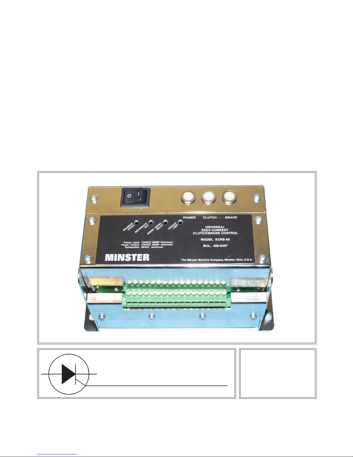
Figure 1. SCRB-68 with cover removed.
COMPONENT IDENTIFICATION
—4—
Figure 2. SCRB-68 rear view.
Terminal Strip
Power Switch
Indicators

MINSTER Model SCRB-68 is an electronic control unit
designed to provide controlled excitation for eddy current coupling type variable speed drives. These controls are compatible with Dynamatic, Louis-Allis
Adjusto-Spede and Torspec drives and with WER
drives that are equipped with special 90 volt D.C. coupling coils. The control consists of a rugged metal housing. The SCRB-68 control may be used with drives
requiring up to 900 watts at 90 volts D.C.
To briefly describe operation, a portion of a regulated
voltage supply, selected by a speed adjusting potentiometer, and a rectified feedback voltage from a
tachometer generator connected to the drive output
shaft, are compared. The error signal obtained is used
to control a silicon controlled rectifier to energize the
coupling. If the reference portion is greater than
tachometer feedback, the coupling is turned “ON.” If
the tachometer feedback is greater, the coupling is
turned “OFF” to produce less output torque and the
optional eddy current brake is fired, to allow output
shaft slowdown.
Extremely fast and accurate speed control is realized
— response time being solely a function of load and
coupling time constants.
The SCRB-68 Control consists of two circuit boards
and housing. A power switch is built-in as a convenient
means of disconnecting power. A torque limiter feature
prevents excitation of the eddy current coupling as long
as motor current exceeds the preselected torque limit
point. A speed sensitive relay drive feature is also built
into the control. This feature is used to control energization of a D.C. control relay in relation to output
speed of the drive. A precision speed reference signal
which varies in direct relation to the output speed of the
drive is provided for use with programmable controls
requiring a low voltage D.C. tachometer signal.
Three (3) neon indicator lamps are located on top of the
control housing adjacent to the power switch. The “D.C.
Power” indicator lamp will glow with a steady brilliance
whenever the unit is turned on. The other lamps are
used to indicate excitation of the eddy current coupling
or brake as noted. Since the eddy current coupling and
brake coils are constantly being pulsed “ON” and
“OFF,” it is normal for the lamps to glow with varying
brilliance.
The SCRB-68 control is usually used in conjunction
with an external control in which certain preset speeds
can be programmed. With this arrangement, press
speed will immediately and automatically change to the
rate which has been preset for a certain function whenever that function is selected. For variable speed drives
equipped with eddy current brakes, by adding a time
delay relay to this control, the drive can be used as a
flywheel brake to quickly slow the flywheel when the
press is shut off.
—5—
DESCRIPTION
OPERATION
The press drive motor and speed controller are both
energized with the “Drive Start” push button. Torque is
transmitted from the drive motor output shaft through a
set of belts to the flywheel. Once the motor is started,
the drive will continue to accelerate flywheel rotation
until it reaches the speed which has been set on the
speed control located on the operator's control panel.
The speed meter, calibrated in strokes per minute, will
indicate the approximate number of times the slide will
cycle continuously each minute. This speed will be
shown even though the press clutch is not engaged
and the slide is not moving.
The strokes per minute indicator reading may vary
slightly from the actual press speed. Accuracy of the
reading depends, to a great degree, on how closely the
meter is calibrated. A resistance network consisting of
several fixed resistors and a potentiometer are placed
in series with analog type meters to accomplish this
calibration. The digital S.P.M. meter contains an integral calibration network.
Speed of the press will be controlled from the variable
speed selector on the operator's control panel. After a
particular speed has been selected, the control will hold
that speed constant. An exception to this will exist,
however, if a torque limit control is installed and the
torque requirements are in excess of the preset torque
limit point.
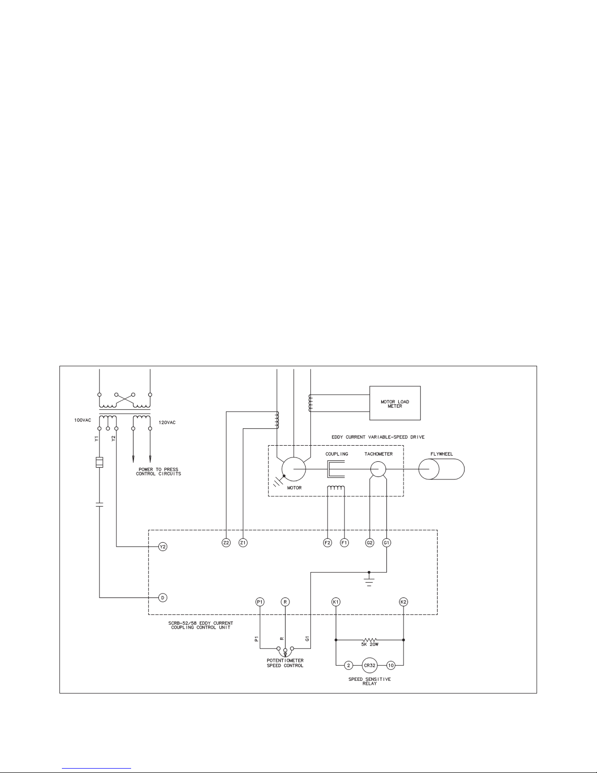
EXPLANATION OF
EDDY CURRENT COUPLING
(See Figure 3)
Before entering into a circuit description of the Eddy
Current Coupling Control, a few preliminary remarks
regarding the principle of eddy current coupling will be
noted. This brief description is offered merely to establish a common background for describing the control
application.
The principle of eddy current coupling makes it possible to obtain a wide range of stepless, adjustable
speeds directly from industrial A.C. power lines at standard frequencies. The drive unit consists of a constant
speed induction motor and an integral magnetic clutch,
or eddy current coupling, assembled in a common
housing. The variable speed output shaft is rotated by
the constant speed A.C. motor through the eddy current coupling.
The eddy current coupling usually consists of three
basic members: the driving member or drum assembly,
the driven member or rotor assembly, and a stationary
member which is the field coil assembly. These basic
components are illustrated schematically in Figures 3
and 4.
A high strength iron drum is connected to the driveshaft
of the constant speed motor and rotates at the speed of
the motor. This drum is the driving member and, in principle, serves as a series of conductor loops as well as
a magnetic flux carrier. The position of the drum is such
that its inner surface surrounds and partially encloses
both field coil and rotor.
The variable speed output shaft is a part of the rotor
assembly and rotates at speeds determined by the
control setting. The cylindrical portion of the rotor lies
between the drum and field coil assemblies and is
divided into magnetically isolated sections by a nonmagnetic metal ring called a magnetic barrier. Poles,
cast into each rotor section, project alternately across
the outer surface of the rotor and are isolated from the
inner surface of the drum by an air gap. As the field coil
is excited, each rotor section assumes a polarity opposite to that of the other section and becomes alternate
north and south magnetic poles.
The field coil assembly is a stationary toroidal coil located concentrically within the rotor assembly. When the
coil is excited, magnetic lines of force emanate from it,
flowing through the north poles of the rotor into the
drum, through the south poles of the rotor and back to
the field assembly. As the drum rotates, the direction of
—6—
Figure 3. SCRB-52/58 Coupling control.
magnetic flux changes at any given point between
these eddy currents and the magnetic field produces a
drag, or relative torque, to be transmitted from the drum
to the rotor and the output shaft connected directly to it.
With no current flowing through the coupling coil, the
rotor and drum assemblies are free to rotate independently of each other. Under this no current condition,
the drum assembly will rotate at full motor speed with
little or no rotation of the output shaft. As current is
applied to the coil, the output shaft accelerates. Output
shaft speed will continue to increase, as long as the coil
remains energized, until it is rotating at a speed slightly less than the speed of the input member. Speed of
the output shaft will never exactly match that of the
motor since some slip is required to transmit torque.
Slip, in this case, refers to speed difference between
the two rotating members. With the control automatically varying the amount of coupling coil excitation, output shaft speed can be held to the preselected rate.
A tachometer generator is attached to the output shaft.
This is an alternating current device whose output frequency varies in direct proportion to the speed of the
output shaft. This voltage is fed into the SCRB-68 control where it is converted from a frequency signal to a
voltage. This voltage is compared with a reference volt-
age so that speed control can be constantly maintained. A portion of the tachometer voltage is also used
to operate the strokes per minute indicator.
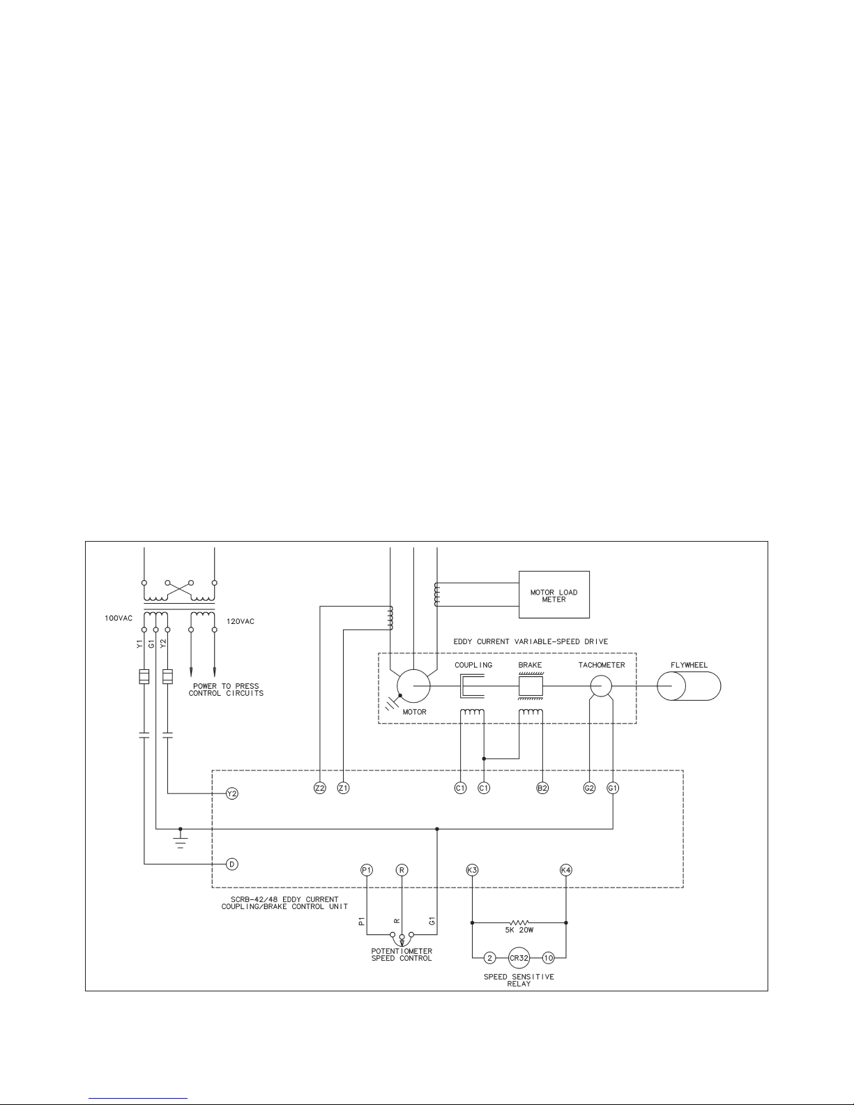
EDDY CURRENT BRAKE
Eddy current drive units may be ordered complete
with eddy current brakes for the purpose of quickly
slowing speed of the output shaft. The eddy current
brake is located within the coupling housing and consists of a brake field coil assembly and the brake
rotor.
The brake field assembly is attached to the coupling
housing and includes a toroidal field coil which is surrounded by two field end rings to form an electromagnet. Poles are cast into the inner surfaces of the end
rings and machined to allow an air gap between the
rings and rotor assembly.
The brake rotor is keyed to the coupling output shaft
and rotates inside the field assembly. If no current is
applied to the brake field coil, no braking torque is
developed. However, as the field coil is excited, eddy
currents are induced in the rotating assembly which
interacts with the stationary field to develop braking
torque. Amount of braking torque may be controlled
by changing excitation of the brake coil.
—7—
Figure 4. SCRB-42/48 coupling/brake control.

FUNCTION OF THE SPEED
SENSE RELAY
Certain types of feeds, tooling, and threading devices
must be started at slow speed. However, once these
parts are in motion, their speed may be increased for
more efficient operation. In order that the press may be
started at speeds commensurate with the tolerable
starting rate of these auxiliary devices, preset controls
may be built-in to automatically reduce speed of the
drive whenever the press is stopped.
The speed sensitive relay is used as a checking device
to make certain speed has been reduced adequately
prior to engagement of the press clutch. If motor output
speed is too fast for an acceptable starting rate, the
relay will open contacts in the control run circuit to prevent press clutch engagement.
The speed range through which the speed sensitive
relay is energized can be changed. Adjustment procedures are explained below.
CHASSIS AND PANEL
MOUNTED COMPONENTS
INDICATOR LIGHTS
A neon indicator light, labeled “POWER,” is connected
across the output terminals of the D.C. power supply
rectifier bridge. Failure of the lamp to glow would indicate failure of power supply bridge or lack of A.C. input
power.
Additional neon indicator lamps (CLUTCH and
BRAKE) are connected across the coupling and brake
coils to serve as an indication of coil excitation. To
accurately measure the amount or presence of a small
excitation voltage on the coupling or brake, a D.C. voltmeter should be used since a rather large “threshold”
voltage is needed to light neon indicators. This excitation voltage can be signal checked between terminals
3 (F2/C2) and 5 (F1/C1 signal) or terminals 4 (B2 signal) and 6 (C1 signal) for the coupling (clutch) or brake
respectively.
POWER OFF/ON
A power switch is mounted on the face of the SCRB-68
Eddy Current Coupling Control and provides a convenient means of disconnecting power from the control
should the need occur.
CONTROL TRANSFORMER
The voltage from the control transformer is dependent
on what the voltage of the motor coils are rated. In
most cases the motor coils are rated at 90 volts so an
isolated 100 volt secondary transformer winding is necessary to supply A.C. power to the control. If the motor
coils were rated at 115 volts then a 125 volts secondary
transformer winding would be required. This winding is
usually auxiliary to the main control transformer. Applications with an eddy current brake require this winding
to have a center tap. This center tap is grounded and
also connected to terminal 7.
FUSES
The supply voltage must be fused in all applications of
the SCRB-68 Eddy Current Coupling Control.
—8—
Figure 5. SCRB-52/58 Coupling control.
MINSTER®

ADJUSTMENTS
Before attempting any adjustments, set the four
potentiometer adjustment screws to their initial values. All four screws are 25 turn potentiometers. You
will hear a click every turn when you reach the clockwise or counter-clockwise end of the potentiometer.
Set ‘MAXIMUM SPEED’ full clockwise.
Set ‘REFERENCE OUT’ full clockwise.
Set ‘SPEED SENSE RELAY’ full clockwise.
Set ‘TORQUE LIMIT’ full counter-clockwise.
MAXIMUM SPEED POTENTIOMETER
An adjustment of the maximum speed potentiometer is
used to match the tachometer generator, located in the
drive, to the control. The potentiometer is located on
the SCRB-68 unit and is labeled “Maximum Speed” and
is located first from the left when viewing the control.
The potentiometer is accessible through an opening on
the front panel. (Refer to Figure 4.)
Once properly adjusted, normally no further attention
need be given this item. Improper adjustment of the
maximum speed potentiometer may result in one of the
following:
1. Drive reaches full speed before operator's speed
control selector is set to maximum. This situation
results in the control running wide open in an attempt
to increase the speed of the drive, but full rated
speed is already being attained, and further speed
increase is not possible. While the control is rated
sufficiently to provide full output continuously, it must
be recognized that this condition is abnormal, and
that control life will be less than it would were proper
operation followed. Normal output voltage of the
control to the coupling will not exceed 60 volts D.C.
at full rated load and speed of drive even though this
output voltage may be 90 volts D.C. during drive
acceleration. It should be noted that this abnormal
condition reflects little, if any, additional load on the
A.C. drive motor itself, due to the nature of the drive.
When the control reacts in the manner just
described, a counterclockwise adjustment of the
maximum speed potentiometer is needed.
2. The drive does not reach full speed even with the
operator's speed control set to maximum. This condition is the result of too much tachometer voltage
being applied and can be corrected by turning the
maximum speed potentiometer adjustment screw in
the clockwise direction. Turning adjustment screw in
this direction will insert additional resistance in the
tachometer circuit.
NOTE: The maximum speed potentiometer will in no
way increase the maximum speed capabilities
of the drive. It will not affect trip out of motor
overload relays, nor will it assist in getting an
inoperative control working. This potentiometer
should not be used as a “Stop” to reduce maximum speed capabilities, since better arrangements are available for this purpose.
TO ADJUST THE MAXIMUM
SPEED POTENTIOMETER:
Required Equipment: A.C. Voltmeter with 0 - 75 or 0 100 V.A.C. range.
With flywheel only running, set operator's speed control
to the position for maximum speed. Presses with preset starting speeds will not respond to the operator's
speed control under these circumstances, since this
control is not effective until the press clutch is engaged.
In this situation, the preset potentiometer itself may be
temporarily adjusted fully clockwise to run drive to full
speed. More than one preset speed may exist, in which
case it will be necessary to use the proper one depending on selector switch setting. For example, if selector
switch is set on “INCH”, and an “Inch Speed” preset
potentiometer exists, then this one must be used to
obtain temporary full speed. If a low speed maximum
limit exists on the preset speed controls, remove the
wire connected to terminal 9 (R signal) of the SCRB-68
control and temporarily jumper terminals 9 (R signal)
and 8 (P1 signal). This will give the effect of full reference speed applied to the control.
Once full speed is obtained from the drive, with flywheel only running, connect the A.C. voltmeter probes
to terminals 7 (G1 signal) and 12 (G2 signal) (tachometer generator leads). Reading should be at least 40
volts A.C. with a 1700 RPM drive.
NOTE: Allow enough time when adjusting the Maxi-
mum Speed Potentiometer for the drive to
reach a stable speed. This potentiometer
requires 25 turns of the adjustment screw for
full range of adjustment.
The Maximum Speed Potentiometer adjustment screw
should now be turned clockwise until no further
increase in measured voltage occurs. Read this voltage accurately. Multiply the voltage so obtained by .95
and adjust the Maximum Speed Potentiometer counterclockwise until the calculated, or 95% value, is indicated on the voltmeter.
As a further reference, with flywheel only running, the
coupling coil voltage measured between terminals 5
(C2 signal) and 7 (G1 signal) should be about 5 to 10
volts D.C. - (Continue to next page.)
—9—

Remove jumper wires from terminals 9 (R signal) and
8 (P1 signal); then reconnect the appropriate wire
securely to terminals 9 (R signal). Adjustment of the
Maximum Speed Potentiometer is now completed.
TO ADJUST THE TORQUE
LIMIT POTENTIOMETER:
Required Equipment: If press is equipped with a “Per-
cent of Load” meter, no other equipment will be needed. If this meter is not furnished, a snap-around type
ammeter may be used. Range of the ammeter should
cover at least 200% of the motor full load current.
NOTE: If a snap-on ammeter is used, place the meter
tongs around one of the “T” leads going to the
main drive motor.
Adjustment of the Torque Limit Potentiometer is made
to prevent firing of the coupling SCR whenever A.C.
motor current exceeds the preset value. This potentiometer is located on the SCRB-68 unit and is labeled
“Torque Limit” and is located last from the left when
viewing the control. This potentiometer is accessible
through an opening on the front panel. To adjust, start
drive from rest and promptly turn speed control to the
maximum speed position. While flywheel is accelerating from rest to full speed, adjust the Torque Limit
Potentiometer so as to cause the motor current indicator to fluctuate between 100% and 150% of full load.
The operator’s speed control, or one of the preset
potentiometers (as explained under maximum speed
adjustment) should be used to control the speed for this
setting. It is suggested that the slide not be cycled while
making this adjustment.
Care should be taken when making this adjustment
since too tight an adjustment will prevent any excitation
of the coupling, and too little will prevent any torque limiting action.
TO ADJUST OPERATING POINT
OF SPEED SENSE RELAY:
Required Equipment: D.C. Voltmeter with 0 - 150
V.D.C. range. The potentiometer is located on the
SCRB-68 unit and is labeled “Speed Sense Relay” and
is located third from the left when viewing the control.
The operating point of the speed sensitive relay is
adjustable by a potentiometer accessible through an
opening on the front panel. It can be set to operate at
practically any speed falling within the range of the
press.
A D.C. voltmeter may be used as an indicator to show
when the relay is energized. Set meter range to the 0150 volt scale, attach negative probe to control terminal
16 (K2 signal) and positive probe to terminal 15 (K1 sig-
nal). When the relay is energized, meter reading will be
approximately 90 volts D.C. in the de-energized state,
only about 10 V.D.C will be indicated.
To Set Relay Operating Point:
1. Start press drive motor and adjust operator’s speed
control or one of the preset potentiometers (as
explained under maximum speed potentiometer
adjustment) to the speed desire for the operating
point of the relay. Allow sufficient time for the drive
to stabilize at the selected speed.
2. Set voltmeter to 0-150 V.D.C. range and attach
probes to control terminals 15 (+) and 16 (-).
3. If D.C. meter indicates relay is energized, turn
speed sense relay adjustment screw, counterclockwise until relay de-energizes. If relay is de-energized, turn the adjusting screw clockwise until the
relay is energized.
4. Double check adjustment by varying press speed
through the selected speed operating point and
observing relay drop out point. Make further fine
adjustments, if necessary.
5. Adjustment is now complete. Disconnect and
remove D.C. voltmeter.
TO ADJUST THE STROKES
PER MINUTE METER:
Voltage from the tachometer generator (in the eddy
current drive) is used to operate the strokes per minute
meter. That meter is essentially a voltmeter calibrated
in strokes per minute. Because of the variation in
speeds, meters and tachometer generator voltages, a
means of adjusting the meter to the actual press speed
is provided. Some of the meters are A.C. types while
others are D.C. operated; therefore, the type of calibration network furnished will depend upon the meter.
Calibration instructions are included for the most popular arrangements. Follow instructions matching the
arrangement furnished.
When calibrating the S.P.M. meter, determine the actual number of strokes per minute that the press is running by observing the stroke counter (if furnished), by
using a mechanical hand tachometer, or by actual
count.
The Bul. 490-0246 Digital S.P.M. Meter contains an
integral calibration network. Refer to the separate
Technical Bulletin, 193 or 2007, which is included in the
composite Service & Operating Manual, for detailed
calibration instructions on this unit.
— 10 —

— 11 —
REFERENCE OUT (PLC ANALOG INPUTS):
The reference out potentiometer is located on the front
of the SCRB-68 unit.
For PLC analog inputs, the output level is typically set
at 95% of the maximum allowable input voltage. For
example, with an analog input range configured for 010 volts DC, the output voltage would be adjusted so
that 9.5 volts DC is present when the output terminals
(Terminals located on outside edge of the board same
as the adjustment potentiometers) when the drive is at
full speed. Note also that the output voltage must be
something less that 13 volts DC since it is internally limited to that level.
With the flywheel only running set the speed control to
maximum speed. Once full speed is obtained from the
drive, connect a voltmeter to the terminals on the II
board.
Allow sufficient time when adjusting the output scaling
potentiometer for output voltage stabilize. This potentiometer requires 25 turns of the adjustment for full
range of adjustment.
The output scaling potentiometer should now be turned
to obtain desired output voltage at full speed. Turn
adjustment screw clockwise to increase output level or
counterclockwise to decrease the level.

CONTROL REPLACEMENT
The SCRB-68 is the latest in a series of eddy current
adjustable speed drive controls produced by MINSTER. This latest generation unit incorporates the
functions of all of the previous controls. As such it can
replace any of those previous controls. There are three
options to replace the existing eddy current control with
the SCRB-68.
Option A: Conversion from a SCRB-52/58 to a
SCRB-68
Option B: Conversion from a SCRB-42/48 to a
SCRB-68
Option C: Conversion from a SCR-22/28 to a
SCRB-68
WARNING
VOLTAGE THAT COULD BE FATAL TO HUMAN LIFE
IS PRESENT WITHIN THE ELECTRICAL CONTROL
CIRCUITS. ONLY AUTHORIZED, EXPERIENCED
PERSONNEL SHOULD ATTEMPT THE INSTALLATION AND SERVICING OF ELECTRICAL EQUIPMENT.
Option A: Conversion from a SCRB-52/58 to a
SCRB-68
When replacing a SCRB-52 Control Unit with a SCRB68 Control Unit, a 3.2 Amp fuse must be installed in the
100 volt AC power-in circuit and when replacing a
SCRB-58 Control, a 10 Amp fuse must be installed.
— 12 —
!
Figure 6. SCRB-52/58 replacement worksheet.

The fuse is to be installed in series with the terminal 1
of the SCRB-68 control. Follow the procedure outlined
below to replace the SCRB unit and install the fuse.
1. Place the POWER, OFF-ON Selector Switch in the
OFF position and lock the electrical disconnect
switch in the OFF position. Then open the electrical
control panel to obtain access to the SCRB-52/58
unit.
2. Disconnect the wires from the terminals on the
SCRB-52/58 unit. The wires will be re-connected to
the new unit, therefore, make certain the wires are
labeled before disconnecting them. Also the correct
wire number from the wire being taken off of the
SCRB-52/58 should be written into the blanks
above the terminals on Figure 6.
3. Loosen the four (4) mounting screws that secure
the SCRB-52/58 unit to the panel just enough to
permit removal of the unit. Then remove the unit
from the control panel.
4. Install the SCRB-68 unit in the control panel and
tighten the four (4) associated mounting screws
securely.
5. Connect the wires (previously removed in Step 2) to
the terminals on the SCRB-68 unit. Refer to Figure
6 for wiring details.
NOTE: A jumper must be installed between termi-
nals 5 and 7 on the SCRB-68. Failure to
install this jumper will result in an inoperable
SCRB-68.
6. The fuse holder (furnished) should be installed as
close to the 100 Volt transformer as possible. Begin
by drilling and tapping two (2) #10 - 24 holes in the
control panel to anchor the fuse holder. Then mount
and secure the fuse holder to the panel.
CAUTION
WHEN DRILLING AND TAPPING HOLES FOR THE
FUSE HOLDER MAKE SURE THAT NO METAL
SHAVINGS FALL ON ANY CIRCUIT BOARDS OR
ANY OTHER ELECTRIC DEVICES.
7. Remove the wire from terminal “Y1” of the trans-
former and re-label it “1Y1.” (NOTE: Re-label both
ends of the wire.) Then attach the wire to the bottom
side of the fuse.
8. Run a #16 ga. MTW grade wire (or equivalent) from
the top of the fuse to terminal “Y1” of the 100 Volt
transformer. Label this wire “Y1.”
9. After completing Steps 1 through 8, close up the
electrical control panel. Then refer to the Adjustment section of this manual.
WARNING
VOLTAGE THAT COULD BE FATAL TO HUMAN LIFE
IS PRESENT WITHIN THE ELECTRICAL CONTROL
CIRCUITS. ONLY AUTHORIZED, EXPERIENCED
PERSONNEL SHOULD ATTEMPT THE INSTALLATION AND SERVICING OF ELECTRICAL EQUIPMENT.
— 13 —
!
!

— 14 —
Option B: Conversion from a SCRB-42/48 to a
SCRB-68
When replacing a SCRB-42 Control Unit with a SCRB68 Control Unit, (2) 3.2 Amp fuses must be installed in
the 100 volt AC power-in circuit and when replacing a
SCRB-48 Control Unit , (2) 10 Amp fuses. The first fuse
is to be installed in series with the terminal 1; the second fuse is to be installed in series with the terminal 2
of the SCRB-68 control.
Follow the procedure outlined below to replace the
SCRB unit and install the two fuses.
1. Place the POWER, OFF-ON selector switch in the
OFF position and lock the electrical disconnect
switch in the OFF position. Then open the electrical
control panel to obtain access to the SCRB-42/48
unit.
2. Disconnect the wires from the terminals on the
SCRB-42/48 unit. The wires will be re-connected to
the new unit, therefore, make certain the wires are
labeled before disconnecting them. Also the correct
wire number from the wire being taken off of the
SCRB-42/48 should be written into the blanks
above the terminals on Figure 7.
3. Loosen the four (4) mounting screws that secure
the SCRB-42/48 unit to the panel just enough to
permit removal of the unit. Then remove the unit
from the control panel.
4. Install the SCRB-68 unit in the control panel and
tighten the four (4) associated mounting screws
securely.
5. Connect the wires (previously removed in Step 2) to
the terminals on the SCRB-68 unit. Refer to Figure
7 for wiring details.
NOTE: A jumper must be installed between termi-
nals 15 and 17 on the SCRB-68. Failure to
install this jumper will result in an inoperable
SCRB-68.
6. The two (2) fuse holders (furnished) should be
installed as close to the 100 Volt transformer as
Figure 7. SCRB-42/48 replacement worksheet.

— 15 —
possible. Begin by drilling and tapping four (4) #10
- 24 holes in the control panel to anchor the fuse
holders. Then mount and secure the fuse holders to
the panel.
CAUTION
WHEN DRILLING AND TAPPING HOLES FOR THE
FUSE HOLDER MAKE SURE THAT NO METAL
SHAVINGS FALL ON ANY CIRCUIT BOARDS OR
ANY OTHER ELECTRIC DEVICES.
7. Remove the wire from terminal “Y1” of the trans-
former and re-label it “1Y1.” (NOTE: Re-label both
ends of the wire.) Then attach the wire to the bottom
side of the first fuse.
8. Run a #16 ga. MTW grade wire (or equivalent) from
the top of the first fuse to terminal “Y1” of the 100
Volt transformer. Label this wire “Y1.”
9. Remove the wire from terminal “Y2” of the transformer and re-label it “2Y2.” (NOTE: Re-label both
ends of the wire.) Then attach the wire to the bottom
side of the second fuse.
10. Run a #16 ga. MTW grade wire (or equivalent)
from the top of the second fuse to terminal “Y2” of
the 100 Volt transformer. Label this wire “1Y2.”
11. After completing Steps 1 through 10, close up the
electrical control panel. Then refer to the Adjustment section of this manual.
WARNING
VOLTAGE THAT COULD BE FATAL TO HUMAN LIFE
IS PRESENT WITHIN THE ELECTRICAL CONTROL
CIRCUITS. ONLY AUTHORIZED, EXPERIENCED
PERSONNEL SHOULD ATTEMPT THE INSTALLATION AND SERVICING OF ELECTRICAL EQUIPMENT.
!
!

Option C: Conversion from a SCR-22/28 to a
SCRB-68
The MINSTER Model SCRB-68 and Model SCR-22/28
eddy current coupling controls are completely interchangeable, even though their physical appearance is
somewhat different. However, since there is a slight difference in terminal strip designation between the units,
this step-by-step procedure has been prepared to aid
the technician in interchanging the controls.
NOTE: A 3.2 amp fuse must be installed in the 100-120
Volt AC control power circuit. Install the fuse in series
with terminal 1 on the SCRB-68 control.
The terminal strip designation of the late Model SCR22/28 control is different from that of earlier models.
This difference appears in the eddy current field coil
terminology and was the result of the motor manufacturer’s changing the designation of these leads from
“C1-C2” for “clutch” to “F1-F2” for “field.” Late model
controls are arranged for the “F1-F2” designation. The
reverse side of the SCR-22 terminal strip also carries
the old terminology and may be turned over, if desired,
so that the strip terminology will match that of the leads.
Both types are shown in Figure 8.
If an optional torque limiter control is attached to the
SCR-22/28 unit, terminals Z1 and Z2 (located on the
torque limiter) should be connected to the motor current transformer. See Figure 8 for details.
The Model SCRB-68 control has a terminal strip similar to that shown in Figure 8.
— 16 —
Figure 8. SCR-22/28 replacement worksheet.

1. Place the POWER, OFF-ON Selector Switch in the
OFF position and lock the electrical disconnect
switch in the OFF position. Then open the electrical
control panel to obtain access to the SCR-22/28
unit.
2. Disconnect the wires from the terminals on the
SCR-22/28 unit. The wires will be re-connected to
the new unit, therefore, make certain the wires are
labeled before disconnecting them. Also the correct
wire number from the wire being taken off of the
SCR-22/28 should be written into the blanks above
the terminals on Figure 9.
3. Loosen the four (4) mounting screws that secure
the SCR-22/28 unit to the panel just enough to permit removal of the unit. Then remove the unit from
the control panel.
4. Install the SCRB-68 unit in the control panel and
tighten the four (4) associated mounting screws
securely.
5. Connect the wires (previously removed in Step 2) to
the terminals on the SCRB-68 unit. Refer to Figure
8 for wiring details.
NOTE: A jumper must be installed between termi-
nals 5 and 7 on the SCRB-68. Failure to
install this jumper will result in an inoperable
SCRB-68.
6. The fuse holder (furnished) should be installed as
close to the 100 Volt transformer as possible. Begin
by drilling and tapping two (2) #10 - 24 holes in the
control panel to anchor the fuse holder. Then mount
and secure the fuse holder to the panel.
CAUTION
WHEN DRILLING AND TAPPING HOLES FOR THE
FUSE HOLDER MAKE SURE THAT NO METAL
SHAVINGS FALL ON ANY CIRCUIT BOARDS OR
ANY OTHER ELECTRIC DEVICES.
7. Remove the wire from terminal “Y1” of the transformer and re-label it “1Y1”. (NOTE: Re-label both
ends of the wire.) Then attach the wire to the bottom
side of the fuse. (See Figure 8.)
8. Run a #16 gauge MTW grade wire (or equivalent)
from the top of the fuse to terminal “Y1” of the 100
Volt transformer. Label this wire “Y1”.
9. After completing Steps 1 through 8, close up the
electrical control panel. Then refer to the Adjust-
ment section of this manual.
While the SCR-22/28 control uses a 500 ohm speed
control potentiometer, and the SCRB-68 uses a 1000
ohm potentiometer, use of the 500 ohm potentiometer
will not damage the SCRB-68. This control should work
normally except in some instances the 15 Volt DC reference supply may lose its controlled regulation, resulting in slight, speed changes if the plant voltage
changes.
If the SCRB-68 control installation is to be permanent,
it is suggested that the 1000 ohm speed control potentiometer be installed.
INSTALLATION NOTE:
A troubleshooting guide is included as a part of this
manual to aid technicians in restoring normal control
functions, should the need occur. It is recommended
that this unit not be dismantled for repair. Minster does
not stock or supply internal components for this unit.
Return unit to Minster for repair.
As mentioned previously, the unit contains potentiometers which must be adjusted to suit operating conditions
of the control.
During the process of troubleshooting a control malfunction, do not overlook the fact that a problem could
exist within the eddy current coupling or its associated
drive motor. Some of the suggested checks in the troubleshooting guide are included to help determine
whether a problem exists in that area.
If it should become necessary to disassemble the
motor or coupling, follow step-by-step procedure outlined in the motor manufacturer’s instructional manual.
If trouble should develop within the tachometer generator, disassembly of the coupling housing will usually
be required since the generator is normally attached to,
or located just inside, the coupling end bell. Use caution when disassembling this part. The tachometer
generator should never be subjected to sharp blows or
heat.
Air-cooled eddy current coupling rotating equipment
requires ample quantities of clean, cooling air. Exhaust
air must be permitted to flow away from the drive and
not be returned. For most efficient use of the equipment, make certain that air inlets and exhaust outlets
are not obstructed in any way that would tend to reduce
air flow or cause recirculation of the heated exhaust air.
Establish periodic cleaning and lubrication schedules
for the drive. Use dry compressed air of moderate pressure to dislodge and remove foreign matter from air
intake screens or louvers. If dirt or foreign matter accumulates inside, it will then become necessary to disassemble the drive in accordance with manufacturer’s
instructions and clean with an approved cleaning solution. At the same time, inspect condition of windings
and insulation. After cleaning, reassemble per instructions.
— 17 —
!

— 18 —
TROUBLESHOOTING GUIDE
TROUBLE
CHECK
UNIT DOES
NOT RUN
AFTER DRIVE
MOTOR HAS
STARTED
1. Make certain 100 volts A.C. exists between terminals 1 (D signal) and 2 (Y2 signal) with the
power switch on. A voltage of approximately 16 volts D.C. between terminals 8 (P1 signal)
and 7(G1 signal) shows presence of the reference voltage. A voltage or approximately 90
volts D.C. between terminals 15 (K1/K3 signal) and 5 (F1/C1 signal) checks the power rectifier bridge. If no D.C. power, or incorrect reference voltage is indicated, suspect trouble in the
control.
2. Make certain that the operator’s speed potentiometer is giving a reference signal to the control. No excitation of the coupling is possible unless the voltage between terminals 9 (R signal) and 7 (G1 signal) is at least .7 volt D.C. with terminal 9 (R signal) positive. The voltage
between terminals 9 (R signal) and 7 (G1 signal) will vary from 0 to 16 volts D.C. depending
upon the setting of the speed potentiometer.
3. Check for D.C. output voltage on coupling terminals 5 (F1/C1 signal) and 3 (F2/C2 signal).
With full excitation, terminal 3 (F2/C2 signal) will be as much as 90 volts D.C. positive. If excitation is present, unit should be running unless the coupling coil circuit is open. To check for
open coupling coil, disconnect power to press and remove wires from control terminals 5
(F1/C1 signal) and 3 (F2/C2 signal). Connect ohmmeter leads to these two wires and check
resistance. Normal resistance is approximately 50 to 65 ohms. If measurement indicates
“open,” check coil connections inside motor drive conduit box. Also, recheck coil resistance
from this point. If coupling coil is “open,” contact local area motor repair shop for installation
of new coil.
4. Check setting of torque limit control.
UNIT SLOWLY
DRIFTS IN
SPEED
1. Torque Limiter may be set incorrectly. Reset torque limiting point per instructions in manual.
2. Check for worn speed control potentiometer or loose wiring connections between it and the
control terminal strip.
3. Operating drive at relatively low output speeds may cause excessive loading and resultant
slowdown.
4. Check for erratic tachometer feedback voltage, A.C., between terminals 7 (G1 signal) and 12
(G2 signal). Rapidly changing voltage here may be caused by loose connections, broken or
shorted wires, or a defective tachometer generator.
UNIT RUNS
ONLY AT FULL
DRIVE MOTOR
SPEED
1. Make certain problem is electrical. Check coupling excitation on terminals 5 (F1/C1 signal)
and 3 (F2/C2 signal). Use D.C. voltmeter (start with 0-150 V.D.C. scale). Connect positive
probe to terminal 3 (F2/C2 signal) and negative to 5 (F1/C1 signal). No excitation voltage
means unit is not energized electrically and problem could be mechanical within the drive.
2. Check D.C. voltage between terminals 9 (R signal) (+) and 7 (G1 signal) (-) to make certain it
is zero when the speed potentiometer is turned down. If not, external speed potentiometer
may be shorted or incorrectly connected.
3. Check for presence of tachometer feedback voltage, A.C., between terminals 7 (G1 signal)
and 12 (G2 signal). Without this feedback, unit will run at full speed with only a small reference voltage applied to terminal R. The tachometer feedback voltage varies from 30 to 60
volts A.C., depending on motor and drive.
4. Turn power switch off on control unit. If the drive remains running, the drive has failed either
through the center bearing locking up or the air gap in the coupling is closed. If this is the
case the motor will need to be repaired by a motor rebuild shop.
FUSES BLOW
1. If operator’s speed potentiometer is turned down and the fuse instantaneously blows an
internal failure may have occurred. Before replacing the unit, check for a direct short across
terminals 5 (F1/C1 signals) and 3 (F2/C2 signals) or terminals 4 (B2 signal) and 6 (C1 signal). A short indication at this point could be the result of a shorted coupling or brake coil,
lead, or associated component in that circuit.

FACTORY CHECKOUT AND REPAIR
If it is determined that a problem exists within the
SCRB-68, it can be returned to the factory for checkout
and repair. Before returning the unit, contact the Minster Repair Parts Department for a Returned Goods
Authorization number (RGA#). This will ensure the
timely return of the repaired unit.
When returning a unit to the factory for repair, make
certain it is carefully packaged to protect it from damage during shipment. Include, with the unit, the RGA#,
a description of the problem(s) encountered and the
serial number of the press on which it is used. Also
include your purchase order covering the work to be
performed and any special shipping instructions concerning return of the unit.
Ship To: The Minster Machine Company
115 North Ohio Street
Minster, Ohio 45865-0120
ATTN: RGA# ________
SPECIFICATIONS
Supply
• Voltage: 100-125VAC
• Power: 900W
• Frequency: 48 to 62 Hz
Input/Output Characteristics
• Coupling: 90VDC-115VDC, 900W
• Brake: 90VDC-115VDC, 900W
• Tachometer: 30-60VAC, 300-800Hz
• Relay Output: 110VDC, 200mA
Miscellaneous
• Dimensions (L × D × H): 231mm (9.125 in.) × 140mm
(5.5 in.) × 130mm (5.125 in.)
• Temperature Range: 0°C to 60°C (32°F to 140°F)
— 19 —
VOLTAGE GUIDE
TERMINALS FUNCTION VOLTAGE REQUIRED WITH DRIVE RUNNING
1 to 2
(Signals D to Y2)
A.C. Supply Voltage 100 Volts A.C.
5 to 15
(Signals F1/C1 to
K1/K3)
D.C. Supply Voltage 90 Volts D.C., 5 (-) and 15 (+)
5 to 3
(Signals F1/C1 to
F2/C2)
Coupling Coil
Excitation Voltage
Normally 5 to 10 Volts D.C. with flywheel only running. Could
increase to 90 volts D.C. with coupling fully energized. 5 (-) and 3 (+)
7 to 12
(Signals G1 to G2)
Tachometer Voltage Approximately 30 to 60 Volts A.C., depending on speed of drive.
8 to 7
(Signals P1 to G1)
Reference Voltage Approximately 16 Volts D.C., 8 (+) and 7 (-)
7 to 9
(Signals G1 to R)
Selected
Reference Voltage
0 to 16 Volts D.C. depending upon setting of speed potentiometer.
7 (-) and 9 (+).

ADDITIONAL COMMENTS:
— 20 —


MMC0311
MINSTER®
The Minster Machine Company, Minster, Ohio 45865, U.S.A.
Phone: (419) 628-2331 / Fax: (419) 628-3517
Distributors strategically located throughout the world.

MMC0311
MINSTER®
The Minster Machine Company, Minster, Ohio 45865, U.S.A.
Phone: (419) 628-2331 / Fax: (419) 628-3517
Distributors strategically located throughout the world.
 Loading...