

Minsk Tractor Works Belarus 1221B.2, Belarus 1221.2, Belarus 1221.3, Belarus 1221.4 Disassembly-assembly Manual

BELARUS
1221.2/1221В.2
1221.3/1221.4
1221-0000010 РРС
DISASSEMBLY-ASSEMBLY MANUAL
Minsk Tractor Works 2010

Due to continual improvement of manufactured articles, design of some assembly
units and parts can be amended without being included in this publication.
Some technical data and figures given in this manual can differ from those actually
installed on your tractor. Overall dimensions and values of mass are approximate (for
reference purpose only). You can obtain more detailed information from your dealer of
trade mark BELARUS.
_______________________________________________________________________
Minsk Tractor Works RUE, 2010
All rights reserved. No part of this manual may be reproduced in any form
whatsoever without written permission of Minsk Tractor Works RUE.

Disassembly-assembly manual for tractor BELARUS-1221.2/1221В.2/1221.3/1221.4
2
CONTENTS
INTRODUCTION ........................................................................................................................................................... 7
1 SAFETY REQUIREMENTS........................................................................................................................................ 8
2 GENERAL ................................................................................................................................................................ 10
3 DISMOUNTING AND MOUNTING OF ENGINE AND ITS SYSTEMS .................................................................... 12
3.1 DISMOUNTING-MOUNTING OF ENGINES MMZ AND DEUTZ .......................................................................... 12
3.2 DISMOUNTING OF SUPERCHARGED AIR COOLER (SAC), MOUNTED ON TRACTORS BELARUS-1221.320
3.3 DISMOUNTING OF SUPERCHARGED AIR COOLER (SAC), MOUNTED ON TRACTORS BELARUS-1221.4
WITH ENGINE MMZ ................................................................................................................................................... 21
3.4 DISMOUNTING OF SUPERCHARGED AIR COOLER (SAC), MOUNTED ON TRACTORS BELARUS-1221.4
WITH ENGINE DEUTZ ................................................................................................................................................ 22
3.5 DISMOUNTING-MOUNTING OF COOLING SYSTEM MOUNTED ON TRACTORS BELARUS-1221.4 WITH
ENGINE MMZ .............................................................................................................................................................. 23
3.6 DISMOUNTING-MOUNTING OF COOLING SYSTEM MOUNTED ON TRACTORS BELARUS-1221.4 WITH
ENGINE DEUTZ .......................................................................................................................................................... 24
3.7 DISMOUNTING-MOUNTING OF COOLING SYSTEM MOUNTED ON TRACTORS BELARUS-
1221.2/1221В.2/1221.3 WITH ENGINE MMZ ............................................................................................................. 25
3.8 DISASSEMBLY-ASSEMBLY OF FUEL TANK 1221-1101500, MOUNTED ON TRACTORS BELARUS-
1221.2/1221В.2/1221.3/1221.4 WITH ENGINES MMZ AND DEUTZ, WITH TWO CYLINDERS OF LIFT LINKAGE
(HYDRAULIC LIFT OF THE HYDRAULIC SYSTEM) ................................................................................................. 26
3.9 DISASSEMBLY-ASSEMBLY OF AIR PURIFIER UNIT MOUNTED ON TRACTORS BELARUS-
1221.2/1221В.2/1221.3/1221.4 (MMZ) ....................................................................................................................... 28
3.10 DISASSEMBLY-ASSEMBLY OF AIR PURIFIER UNIT MOUNTED ON TRACTORS BELARUS-1221.4 DEUTZ
..................................................................................................................................................................................... 29
3.11 DISASSEMBLY-ASSEMBLY OF EXHAUST SYSTEM OF TRACTORS BELARUS-1221.4 ............................. 30
3.12 DISASSEMBLY-ASSEMBLY OF FUEL SUPPLY CONTROL MOUNTED ON TRACTORS BELARUS-1221В.2
..................................................................................................................................................................................... 32
3.13 DISASSEMBLY-ASSEMBLY OF FUEL SUPPLY CONTROL, MOUNTED ON TRACTORS BELARUS-
1221.2/1221.3 .............................................................................................................................................................. 34
3.14 DISASSEMBLY-ASSEMBLY OF FUEL SUPPLY CONTROL, MOUNTED ON TRACTORS BELARUS-1221.4
WITH ENGINES MMZ И DEUTZ ................................................................................................................................ 36
4 TRANSMISSION ...................................................................................................................................................... 37
4.1 TRANSMISSION DISASSEMBLY (GENERAL PROVISIONS) ............................................................................ 39
4.2 UNIT-BY-UNIT DISASSEMBLY ............................................................................................................................ 39
4.2.1 DISCONNECTING ENGINE FROM TRANSMISSION (TRACTOR DISCONNECTION) .................................. 39
4.2.2 DISMOUNTING (DISCONNECTION) OF CLUTCH COUPLING BODY ........................................................... 40
4.2.3 DISMOUNTING (DISCONNECTION) OF GEAR BOX BODY ........................................................................... 42
4.2.4 TRANSMISSION ASSEMBLY ............................................................................................................................ 43

Disassembly-assembly manual for tractor BELARUS-1221.2/1221В.2/1221.3/1221.4
3
4.3 CLUTCH ................................................................................................................................................................ 44
4.3.1 DISASSEMBLY-ASSEMBLY OF CLUTCH CONTROL UNITS BELARUS-1221.2/1221.3/1221.4 ................... 44
4.3.1.1 DISASSEMBLY-ASSEMBLY OF CLUTCH CONTROL UNITS FOR BELARUS-1221В.2 ............................. 45
4.3.2 DISASSEMBLY-ASSEMBLY OF CLUTCH COUPLING .................................................................................... 48
4.3.3 MOUNTING DISKS OF CLUTCH COUPLING ON ENGINE FLYWHEEL ......................................................... 51
4.3.4 ADJUSTING POSITION OF SQUEEZE LEVERS ............................................................................................. 51
4.3.5 REDUCTION GEAR SECTION OF CLUTCH COUPLING BODY ..................................................................... 53
4.3.6 DISASSEMBLY OF THE REDUCTION GEAR SECTION OF CLUTCH COUPLING BODY ............................ 54
4.3.7 ASSEMBLY OF CLUTCH COUPLING BODY ................................................................................................... 65
4.4 GEAR BOX ............................................................................................................................................................ 66
4.4.1 DISASSEMBLY OF GEAR BOX. DISMOUNTING GEAR BOX......................................................................... 66
4.4.2 DISMOUNTING HYDRAULIC SYSTEM UNITS, GEARS’ ASSEMBLY AND GEAR SHIFTING YOKES ......... 67
4.4.3 DISASSEMBLY OF GEARS’ ASSEMBLY ......................................................................................................... 71
4.4.5 DISASSEMBLY OF REDUCED GEARS’ SHAFT .............................................................................................. 77
4.4.6 DISASSEMBLY OF GEAR TRAIN SHAFT ........................................................................................................ 80
4.4.7 DISASSEMBLY OF CONTROL MECHANISM .................................................................................................. 84
4.4.8 ASSEMBLY OF GEAR BOX .............................................................................................................................. 85
4.5 REAR AXLE .......................................................................................................................................................... 87
4.5.1 DISASSEMBLY OF REAR AXLE ....................................................................................................................... 87
4.5.2 ASSEMBLY OF REAR AXLE ............................................................................................................................. 94
4.5.3 ADJUSTING REAR AXLE ................................................................................................................................ 100
4.6 BRAKES .............................................................................................................................................................. 104
4.6.1 DISMOUNTING OF PARKING AND RIGHT-SIDE FOOT BRAKE AS AN ASSEMBLY ................................. 105
4.6.2 DISASSEMBLY OF PARKING BRAKE ............................................................................................................ 105
4.6.3 DISASSEMBLY OF LEVER FOR PARKING BRAKE CONTROL ................................................................... 106
4.6.4 DISMOUNTING OF BRAKES’ LEVERS .......................................................................................................... 107
4.6.5 DISMOUNTING OF CLUTCH OF DIFFERENTIAL INTERLOCK (DRY TYPE) .............................................. 107
4.6.6 DISASSEMBLY OF DIFFERENTIAL INTERLOCK CLUTCH .......................................................................... 108
4.6.7 DISMOUNTING OF LEFT-SIDE FOOT BRAKE .............................................................................................. 109
4.6.8 DISASSEMBLY OF TWO-DISK FOOT BRAKE ............................................................................................... 109
4.6.9 DISASSEMBLY OF RIGHT-SIDE THREE-DISK BRAKE ................................................................................ 110
4.6.10 ASSEMBLY OF RIGHT-SIDE THREE-DISK BRAKE (DRY TYPE) .............................................................. 111
4.6.11 ASSEMBLY OF LEFT-SIDE FOOT BRAKE AND DIFFERENTIAL INTERLOCK CLUTCH ......................... 112
4.6.12 ASSEMBLY OF PARKING BRAKE ................................................................................................................ 112
4.6.13 ASSEMBLY OF PARKING BRAKE CONTROL LEVER ................................................................................ 114

Disassembly-assembly manual for tractor BELARUS-1221.2/1221В.2/1221.3/1221.4
4
4.6.14 ADJUSTMENT OF FOOT BRAKE, VALVE AND REGULATOR OF PNEUMATIC SYSTEM PRESSURE .. 115
4.6.15 ADJUSTMENT OF PARKING BRAKE, BRAKE VALVE AND REGULATOR OF PNEUMATIC SYSTEM
PRESSURE ............................................................................................................................................................... 116
4.6.16 MULTI-DISK FOOT AND PARKING BRAKES OPERATING IN OIL BATH .................................................. 117
4.6.18 DISASSEMBLY OF LEFT-SIDE MULTI-DISK BRAKE OPERATING IN OIL BATH ..................................... 119
4.6.19 ASSEMBLY OF LEFT-SIDE BRAKE ............................................................................................................. 121
4.6.20 DISASSEMBLY OF RIGHT-SIDE FOOT BRAKE .......................................................................................... 126
4.6.21 ASSEMBLY OF RIGHT-SIDE FOOT BRAKE ................................................................................................ 130
4.7 DISASSEMBLY-ASSEMBLY OF BRAKES CONTROL ON REVERSAL OF BELARUS-1221В.2 ..................... 135
4.8 DISMOUNTING OF COMPONENTS OF ONE-WIRE PNEUMATIC DRIVE OF TRAILER BRAKES ON
TRACTORS BELARUS-1221.2/1221.3 ..................................................................................................................... 138
4.9 DISMOUNTING OF COMPONENTS OF TWO-WIRE PNEUMATIC DRIVE OF TRAILER BRAKES ON
TRACTORS BELARUS-1221.2/1221.3 ..................................................................................................................... 140
4.10 DISMOUNTING OF COMPONENTS OF COMBINED PNEUMATIC DRIVE OF TRAILER BRAKES FOR
TRACTOR BELARUS-1221.4 WITH ENGINE DEUTZ ............................................................................................. 142
4.11 DISMOUNTING OF COMPONENTS OF ONE-WIRE PNEUMATIC DRIVE OF TRAILER BRAKES FOR
TRACTOR BELARUS-1221.4 WITH ENGINE MMZ ................................................................................................. 145
4.12 DISMOUNTING OF COMPONENTS OF TWO-WIRE PNEUMATIC DRIVE OF TRAILER BRAKES ............. 147
4.13 DISASSEMBLY-ASSEMBLY OF REAR PTO ................................................................................................... 149
4.13.1 DISASSEMBLY-ASSEMBLY OF REAR PTO CONTROL ............................................................................. 159
4.13.2 ADUSTMENT OF PTO ................................................................................................................................... 162
5 FRONT DRIVING AXLE (FDA) .............................................................................................................................. 164
5.1 DRIVE OF FRONT DRIVING AXLE .................................................................................................................... 164
5.1.1 DISASSEMBLY OF FDA DRIVE ...................................................................................................................... 165
5.1.2 ASSEMBLY OF FDA DRIVE ............................................................................................................................ 169
5.1.3 ADJUSTMENT AND TESING FDA DRIVE ...................................................................................................... 172
5.2 DISASSEMBLY OF FDA WITH PLANETARY-CYLINDRICAL REDUCTION GEARS ....................................... 175
5.2.1 DISASSEMBLY OF FDA FINAL DRIVE ........................................................................................................... 175
5.2.2 ASSEMBLY AND ADJUSTMENT OPERATIONS ........................................................................................... 179
5.3 DISASSEMBLY OF PLANETARY-CYLINDRICAL REDUCTION GEAR ............................................................ 183
6 WHEELS AND HUBS ............................................................................................................................................. 194
6.1 MOUNTING-DISMOUNTING WORKS ON WHEEL DISMANTLED FROM TRACTOR..................................... 194
6.2 DISMOUNTING REAR WHEEL AND HUB ......................................................................................................... 196
6.2.1 DISASSEMBLY-ASSEMBLY OF REAR WHEEL HUB .................................................................................... 196
7 STEERING ............................................................................................................................................................. 197
7.1 DISASSEMBLY-ASSEMBLY OF UNITS OF HYDROSTATIC STEERING CONTROLMOUNTED ON
TRACTORS BELARUS-1221.2/1221.3/1221.4 WITH ENGINE MMZ» .................................................................... 197

Disassembly-assembly manual for tractor BELARUS-1221.2/1221В.2/1221.3/1221.4
5
7.1.1 DISASSEMBLY-ASSEMBLY OF UNITS OF THE HYDROSTATIC STEERING CONTROLMOUNTED ON
TRACTORS BELARUS-1221.4 WITH ENGINE DEUTZ» ........................................................................................ 201
7.1.2 DISASSEMBLY-ASSEMBLY OF UNITS OF THE HYDROSTATIC STEERING CONTROLMOUNTED ON
TRACTORS BELARUS-1221В.2 .............................................................................................................................. 204
7.2 STEERING COLUMN .......................................................................................................................................... 207
7.2.1 DISASSEMBLY-ASSEMBLY OF STEERING COLUMN ................................................................................. 2 07
7.2.2 DISASSEMBLY-ASSEMBLY OF STEERING COLUMN OF THE REVERSE CONTROL STATION ............. 214
7.3 DISASSEMBLY OF STEERING ROD ................................................................................................................. 219
8 CABIN ..................................................................................................................................................................... 220
8.1 DISMOUNTING AND MOUNTING OF THE CABIN ........................................................................................... 220
8.2 DISMOUNTING-MOUNTING OF FACIA OF TRACTOR BELARUS-1221.2/1221В.2 ....................................... 225
8.3 DISMOUNTING-MOUNTING FACIA OF TRACTORS BELARUS-1221.3/1221.4 ............................................. 226
8.4 DISASSEMBLY-ASSEMBLY OF FACIA PANELS OF THE RIGHT-SIDE PANEL ............................................ 228
8.5 DISASSEMBLY-ASSEMBLY OF PANELS 85-6702550 OF FRONT CABIN WALL .......................................... 229
8.6 DISASSEMBLY-ASSEMBLY OF REAR WHEELS’ FENDERS .......................................................................... 230
8.6.1 DISASSEMBLY-ASSEMBLY OF PLASTIC FENDERS OF TRACTORS’ REAR WHEELS ............................ 230
8.6.2 DISASSEMBLY-ASSEMBLY OF METAL FENDERS OF TRACTORS’ REAR WHEELS ............................... 231
8.7 DISASSEMBLY-ASSEMBLY OF FRONT WHEELS’ FENDERS OF TRACTORS BELARUS-1221 AND
MODIFICATIONS ...................................................................................................................................................... 233
8.8 DISMOUNTING-MOUNTING OF AIR CONDITIONER (OPTION) MOUNTED ON TRACTORS BELARUS-
1221.3/1221.4 ............................................................................................................................................................ 234
8.9 CHECK AND ADJUSTMENT OF TENSION OF THE BELT OF AIR CONDITIONER COMPRESSOR DRIVE 237
9 HYDRAULIC HINGE SYSTEM .............................................................................................................................. 239
9.1 DISASSEMBLY-ASSEMBLY OF HYDRAULIC HINGE UNITS. ......................................................................... 239
9.1.1 DISASSEMBLY-ASSEMBLY OF HYDRAULIC SYSTEM ASSEMBLIES ........................................................ 246
9.2 DISASSEMBLY-ASSEMBLY OF REAR HINGE DEVICE (RHD) OF TRACTOR EQUIPPED WITH HYDRAULIC
HOIST ........................................................................................................................................................................ 252
9.3 DISASSEMBLY-ASSEMBLY OF LIFTING TYPE TRACTIVE-DRAWING DEVICE (TDD) WITH HYDRAULIC
HOIST ........................................................................................................................................................................ 254
10 DISASSEMBLY-ASSEMBLY OF SEMI-FRAME AND BALLAST ........................................................................ 257
10.1 DISASSEMBLY-ASSEMBLY OF SEMI-FRAME OF TRACTORS BELARUS-1221.2/1221В.2/1221.3/1221.4
................................................................................................................................................................................... 257
10.2 DISASSEMBLY-ASSEMBLY OF BALLAST ..................................................................................................... 258
10.3 DISCONNECTION OF FRONT BEAM FROM ENGINE DEUTZ ...................................................................... 259
11 ELECTRICAL EQUIPMENT ................................................................................................................................. 260
11.1 DISMOUNTING-MOUNTING OF ELEMENTS OF THE ELECTRICAL EQUIPMENT FOR ENGINES
MOUNTED ON TRACTORS BELARUS-1221.2/1221В.2/1221.3/1221.4 WITH ENGINES MMZ И DEUTZ ........... 260

Disassembly-assembly manual for tractor BELARUS-1221.2/1221В.2/1221.3/1221.4
6
11.1.1 DISMOUNTING ELEMENTS OF ELECTRICAL EQUIPMENT OF ENGINE (MMZ) MOUNTED ON
TRACTORS BELARUS-1221.2/1221В.2 .................................................................................................................. 261
11.1.2 DISMOUNTING ELECTRICAL EQUIPMENT ELEMENTS OF ENGINE (MMZ) MOUNTED ON TRACTORS
BELARUS-1221.3 ...................................................................................................................................................... 262
11.1.3 DISMOUNTING ELECTRICAL EQUIPMENT ELEMENTS OF ENGINES (MMZ OR DEUTZ) MOUNTED ON
TRACTORS BELARUS-1221.4 ................................................................................................................................. 262
11.2 DISASSEMBLY-ASSEMBLY OF STORAGE BATTERY COMPARTMENT AND STARTING SYSTEM
ELEMENTS MOUNTED ON TRACTORS BELARUS-1221.2 .................................................................................. 265
11.3 DISASSEMBLY-ASSEMBLY OF STORAGE BATTERY COMPARTMENT AND STARTING SYSTEM
ELEMENTS MOUNTED ON TRACTORS BELARUS-1221В.2/1221.3/1221.4 WITH ENGINES MMZ AND DEUTZ»
................................................................................................................................................................................... 267
11.3.1 DISMOUNTING ELEMENTS OF STORAGE BATTERY COMPARTMENT .................................................. 267
11.4 DISMOUNTING-MOUNTING OF ELEMENTS OF TRANSMISSION ELECTRICAL EQUIPMENT ................. 269
11.5 CONTROL OF TRACTOR UNITS ..................................................................................................................... 272
11.5.1 CONTROL OF REAR HINGE DEVICE (RHD) 1221 – 8700610 MOUNTED ON TRACTORS BELARUS-
1221.2/1221В.2 ......................................................................................................................................................... 272
11.5.2 OPERATIONS TO BE PERFORMED WHEN DISMOUNTING/MOUNTING CABIN: ................................... 273
11.6 CONTROL OF DI, FDA AND FRONT PTO 1221-8700210-Д (ELECTRICAL PART) MOUNTED ON
TRACTORS BELARUS-1221.3 ................................................................................................................................. 278
11.7 CONTROL OF DI, FDA, PTO AND REDUCTION GEAR 1221-8700250-Д (ELECTRICAL PART) MOUNTED
ON TRACTORS BELARUS 1221.3 .......................................................................................................................... 281
11.7.2 OPERATIONS TO BE MADE WHEN DISMOUNTING-MOUNTING THE CABIN: ........................................ 283
11.8 CONTROL OF DI AND FDA, MMZ OR DEUTZ, (ELECTRICAL PART) MOUNTED ONTRACTORS BELARUS
1221.4 ........................................................................................................................................................................ 285
11.8.1 OPERATIONS TO BE PERFORMED WHEN REPLACING ENGINE: .......................................................... 286
11.8.2 OPERATIONS TO BE MADE WHEN DISMOUNTING-MOUNTING THE CABIN: ........................................ 287
11.9 CONTROL OF ENGINE DEUTZ 1221.4 – 8700910-Б, MOUNTED ON TRACTORS BELARUS 1221.4 ........ 289
11.9.1 OPERATIONS TO BE PERFORMED IN REPLACING ENGINE: ................................................................. 290
11.9.2 OPERATIONS TO BE PERFORMED WHEN DISMOUNTING/MOUNTING CABIN: ................................... 290
11.10 CONTROL OF ENGINE MMZ 1221.4 – 8700910-М, MOUNTED ON TRACTORS BELARUS 1221.4 ......... 291
11.10.1 OPERATIONS TO BE PERFORMED IN REPLACING ENGINE: ............................................................... 292
11.10.2 OPERATIONS TO BE PERFORMED WHEN DISMOUNTING/MOUNTING CABIN: ................................. 292
11.11 DISMOUNTING-MOUNTING AND DISASSEMBLY-ASSEMBLY OF DASHBOARD .................................... 293
11.11.1 DISMOUNTING-MOUNTING OF DASHBOARD 80-3805010-Д1 MOUNTED ON TRACTORS BELARUS-
1221.2/1221В.2 ......................................................................................................................................................... 293
11.11.2 DISMOUNTING OF DASHBOARD MOUNTED ON TRACTORS BELARUS-1221.3/1221.4 ..................... 297

Disassembly-assembly manual for tractor BELARUS-1221.2/1221В.2/1221.3/1221.4
7
INTRODUCTION
This manual contains procedure of disassembly-assembly of units and assemblies, data on
their design and operation, adjustment and technical characteristics of units of tractors
BELARUS 1221.2/1221В.2/1221.3/1221.4 with engines MMZ and Deutz. It is an indispensible
guide for maintenance personnel engaged in repair or maintenance.
To obtain exhaustive information about tractors use this manual, as well as “Operating
manual for tractor BELARUS 1221” and its modifications, enclosed with each tractor.
Data contained in this manual is accurate at the time of this manual compilation. As tractors
BELARUS are continually updated, Minsk Tractor Works PA reserves the right to introduce
design amendments without notifying the customers. All data given in this manual can be
amended, and illustrative materials can differ from those describing tractors currently
manufactured.
ATTENTION! Carefully study and strictly follow all directions given below in section "Safety
requirements".
Abbreviations used:
PTO – Power-take-off;
FPTO – Front power-take-off shaft;
FDA – Front driving axle;
GSB – Gear shifting box;
HHS – Hydraulic hinge system;
RHD – Rear hinge device;
FHD – Front hinge device;
HSC – Hydrostatic steering control;
SAC – Supercharged air cooler;
CC – Clutch coupling;
RA – Rear axle;
DI – Differential interlock;
TH – Trailer hitch;
SB – Storage battery.

Disassembly-assembly manual for tractor BELARUS-1221.2/1221В.2/1221.3/1221.4
8
1 SAFETY REQUIREMENTS
For your safety purpose carefully study this manual before starting maintenance and repair
works. Pay particular attention to all warnings and recommendations given in this manual.
Always consult operating and maintenance manual issued by the manufacturer.
1. Any equipment can present danger for personnel. Remember that careless steering or
wrong maintenance can be the source of danger both for an operator and his associates.
2. Strictly follow safety regulations in handling lifting and transport mechanisms. Tractor lifted
above the ground by means of lifting mechanisms and poorly fastened by ropes can fall down on
you. Before jacking one of the axles, put the tractor on hard even surface. Another axle must be
securely blocked with wedges (pads) put under wheels. Do not loll tractor against slag bricks,
hollow tiles or other supports that can collapse by tractor weight. Do not work under tractor lifted
only by jack, and observe all recommendations given in this manual.
3. Before starting to disassembly tractor into components, carefully clean adjacent assembly
units from dust, mud, oil and grease.
4. When disengaging power transmission constituents, use disengagement tool. Securely put
transmission constituents on supports and jacks. Do not rely solely on jacks to support tractor
when working under it: tractor can move from jacks and injure or maim you, unless wheels are
blocked with wedges on both sides. Always block front and rear wheels of tractor which must
always be jacked. Always place raised section of tractor on supports before starting any work.
5. Make sure tractor will remain immobile: shift gear in the gear box, engage parking brake,
shut down the engine and pull out key from starter switch and instruments. Disconnect storage
battery to rule out possibility of starting engine by someone else, while you are working under
tractor.
6. Wear suitable protective cloths (gloves, footwear, working cloths) and goggles.
7. Use serviceable and suitable tools. Self-made (provisional) tools and wrong work techniques
can result in dangerous situation. Use mechanical tools only for loosening fasteners. Use proper
size tools for tightening and loosening fittings. Do not use “inch system” tools for metric fasteners.
Avoid possibility of injuring caused by wrench slippage.
8. To avoid burns take care when draining hot oil from filling tanks of hydraulic system, power
transmission and FDA. Leaks of oil, lubricants, solvents and other liquids that can pollute
environment and be harmful for your health must be properly disposed in accordance with local
legislation and regulations.
9. Refill filling tanks and use only fuel, oils, lubricants and special liquids recommended by the
manufacturer according to annexes “Recommended oils, fuels, lubricants and special liquids” listed
in operating manuals for tractor and engine installed on it.
DO NOT USE OTHER LUBRICANTS!

Disassembly-assembly manual for tractor BELARUS-1221.2/1221В.2/1221.3/1221.4
9
10. For washing parts and assembly units use special washing agents.
When using kerosene or benzene for washing, observe fire safety regulations; make washing in
ventilated premises.
Keep tidy working place where dismounting-mounting works are underway.
11. When checking travel of foot brakes’ pedals, make sure travel of interlocked brakes’ pedals is
90-110 mm with effort of 600 N.
12. Make sure clutch pedal has free travel and reliably returns to initial position. Pedal hang-up in
intermediate positions and at free travel section is not allowed. Clutch must provide full
disengagement, smooth engagement and not slip during operation.
13. Upon completion of repair works related to transmission run-in the tractor for 30 hours at all
gears without load, or use for easy transport works.
ATTENTION! Remember that failure to follow above-listed recommendations can lead to major
injuries and will depreciate your work!

Disassembly-assembly manual for tractor BELARUS-1221.2/1221В.2/1221.3/1221.4
10
2 GENERAL
Tractor BELARUS 1221 and its modifications belong to general purpose row-crop wheeled
tractors of traction class 2 with axle arrangement 4 x 4. They are designed for various agricultural
works with mounted, half-mounted, trailer machines and implements, loading-unloading
mechanisms, driving stationary agricultural machinery, as well as transport works in different
climatic regions.
These tractors are equipped with turbo supercharged six-cylinder diesel.
Tractor is configured according to classical approach. Tractor skeleton is frameless. On the front
skeleton section on the bearer frame diesel is mounted, which is rigidly fastened to clutch coupling
body via spacer.
In front of diesel the bar carries: water radiator of diesel cooling system, radiator of supercharged
air intermediate cooling, condenser of cabin air conditioning (optional).
Straight behind the diesel power transmission mechanisms are arranged: clutch coupling (CC),
gear box (GB), rear axle (RA) with differential interlock (DI), rear power-take-off shaft (PTO).
Clutch coupling – two-disk, friction of constantly closed type.
Gear box is mechanical, synchronized.
Rear axle has final drive, differential, side final drives.
Rear axle (RA) body houses: final drive, differential, final drives – a pair of cylindrical gears, rear
PTO. On driving shafts of final drives foot brakes, parking brake and differential interlock coupling
are installed.
Rear power-take-off (PTO) is synchronous (speed of PTO shank rotation depends on speed of
tractor wheels rotation), and stand-alone (speed of PTO shank rotation doesn’t depend on speed of
tractor wheels rotation), two-speed (rotation speed of stand-alone PTO shank is 540 rev/min and
1000 rev/min). Three types of shanks can be installed: PTO 2 (21 splines), PTO 1с (8 splines), PTO
1с (6 splines) under State Standard GOST 3480. Direction of rotation – – clockwise on the side of
shank end face.
Depending on tractor configuration or version, hydraulic mechanical or electrical hydraulic control
of RA DI, FDA drive can be installed
Front driving axle (FDA) - BELARUS 1221 – with planetary-cylindrical wheeled reduction gears,
self-interlocking differential, conical main drive.
Rear hinge mechanism (RHM) is a three-spot joint four-link device. HM (category 2) is designed
for ganging up agricultural machinery and implements. RHM is mounted (installed) on rear axle
cover and body.
Hydraulic hinge system – separate-aggregate with automatic adjustment of soil tillage depth. The
system has 3 pairs of independent outputs.
Rear hinge mechanism HM-2 of make I according to State Standard GOST 10677 with adjustable
right-side brace and internal interlock of lower connecting rod).
Rear hinge mechanism HM-2 of make I according to State Standard GOST 10677 with adjustable
right-side brace and internal interlock of lower connecting rod.
Tractor has pneumatic drive to provide control of trailer brakes

Disassembly-assembly manual for tractor BELARUS-1221.2/1221В.2/1221.3/1221.4
11
Steering is hydrostatic (HSC); supply pump is of gear type, actuating mechanism – two hydraulic
cylinders of two-way action.
Wheels with pneumatic low-pressure tires. Rear wheels – driving, front wheels – driving and
guiding.
Size of main tires:
front wheels - 420/70R24;
rear wheels - 18.4R38.
The cabin is of protective design providing operator protection if tractor turns over in emergency
situations (complies with requirements of ROPS). The tractor cabin is equipped with cleaner of front
and rear glass, windscreen washer, rear view mirrors.
Natural ventilation is provided through side and rear windows, and hatch.
Fuel tank for tractors with hydraulic lift is made of plastic and is mounted under the cabin in the
tractor middle section.
Diesel is closed with bonnet; for tractors BELARUS 1221.2/1221В.2 – from top without sides
(metal); for tractors BELARUS 1221.3/1221.4 – with removable sides (plastic).
On customer’ order tractor is equipped with additional equipment (spacers for installation of
double wheels, speed reducer, air conditioner, canopy, etc.).
NOTE: All technical characteristics of tractor BELARUS 1221 and its modifications are given in
Operating manuals for tractor and engine mounted on it, that are enclosed with each tractor.
Disassembly-assembly manual for tractor BELARUS-1221.2/1221В.2/1221.3/1221.4
12
3 DISMOUNTING AND MOUNTING OF ENGINE AND ITS SYSTEMS
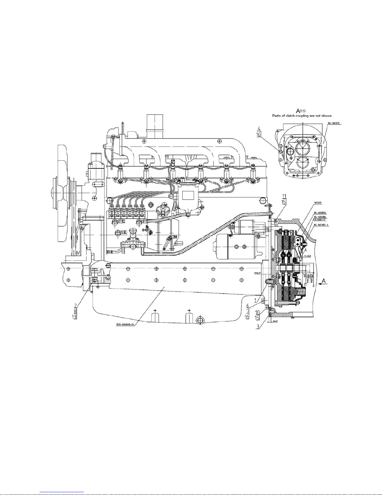
3.1 Dismounting-mounting of engines MMZ and Deutz
Dismounting-mounting engine MMZ, mounted on tractors BELARUS 1221.2/1221В.2/1221.3
Figure 3.1 Mounting engine (MMZ) on tractors BELARUS 1221.2/1221В.2/1221.3/1221.4
а) dismantle tractor facia, see section 8.2 “Dismounting-mounting of facia of tractor BELARUS
1221.2/1221В.2”;
b) drain cooling fluid from the tractor cooling system ;
c) drain oil from engine by having unscrewed plug in bottom section of engine pan
d) drain oil from HSC system, see section 7.1 “Disassembly-assembly of units of hydrostatic
steering mounted on tractors BELARUS 1221.2/1221.3/1221.4 with engine MMZ”;
e) loosen silicon branch pipes of supercharged air cooler, see section 3.2 – “Dismounting
supercharged air cooler (SAC), mounted on tractors BELARUS 1221.3” and section 3.3 –
“Dismounting supercharged air cooler (SAC), mounted on tractors BELARUS 1221.4 with engine
MMZ”;
f) dismantle engine harness:
Disassembly-assembly manual for tractor BELARUS-1221.2/1221В.2/1221.3/1221.4
13
1) for tractors BELARUS 1221.2/1221В.2, see section 11.1.1 “Dismounting elements of engine
electrical equipment (MMZ) mounted on tractors BELARUS 1221.2/1221В.2”;
2) for tractors BELARUS 1221.3, see sections:
- 11.5.4 “Operations performed when replacing engine”;
- 11.6.1 “Operations performed when replacing engine”;
- 11.7.1 “Operations performed when replacing engine”;
g) for tractors BELARUS 1221.4 with engine MMZ, see section 11.10.1 “Operations performed
when replacing engine”;
h) disconnect branch pipes of water radiator from engine, see section 3.7 “Dismounting-mounting
the cooling system, mounted on tractors BELARUS 1221.2/1221В.2/1221.3”;
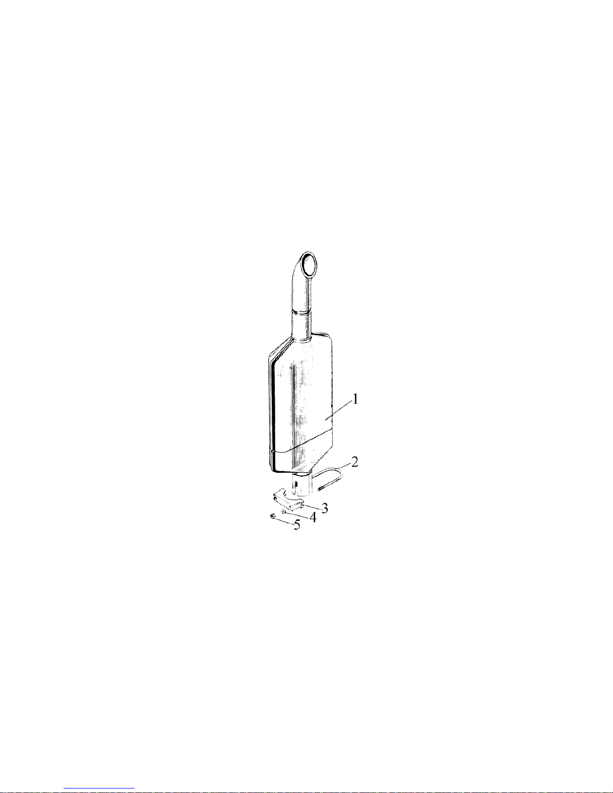
i) dismount muffler 1 (Figure 3.2) by loosening nuts 5 and releasing collar 3;
1 – muffler; 2 – grip; 3 – collar; 4 – washer; 5 – nut.
Figure 3.2 Muffler
Disassembly-assembly manual for tractor BELARUS-1221.2/1221В.2/1221.3/1221.4
14
j) disconnect fuel lines from coarse fuel filter 6 (Figure 3.3), installed only on tractor BELARUS
1221.4 with engine MMZ;
Figure 3.3 Mounting coarse fuel filter on MMZ.
k) dismantle air purifier, as described in section 3.9 “Disassembly-assembly of air purifier unit
installed on tractors BELARUS 1221.2/1221В.2/1221.3/1221.4 (with engine MMZ)”;
l) dismantle HSC metal oil pipes, 11, 12 by disconnecting them from high-pressure sleeves see
(Figure 7.1), section 7.1 “Disassembly-assembly of hydrostatic steering controlunits mounted on
tractors BELARUS 1221.2/1221.3/1221.4 with engine MMZ”, or (Figure 7.6), section
7.1.2 «”Disassembly-assembly узлов of hydrostatic steering controlsystem mounted on tractors
BELARUS 1221В.2”;
n) dismantle cardan shaft of FDA drive;
n) disconnect front engine support from front bar, having unscrewed bolts 1 (Figure 3.4) (only for
engines MMZ);
Disassembly-assembly manual for tractor BELARUS-1221.2/1221В.2/1221.3/1221.4
15
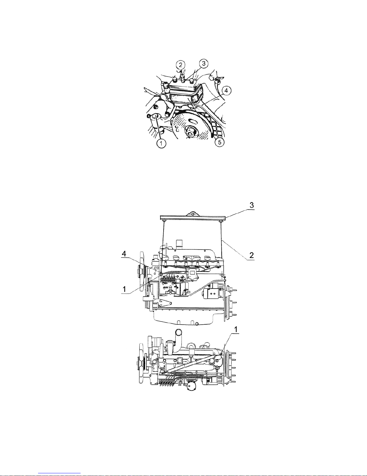
1- support fastening bolt; 2- adjustment bolt; 3- check nut; 4- support; 5- shock absorber
Figure 3.4 Front engine support
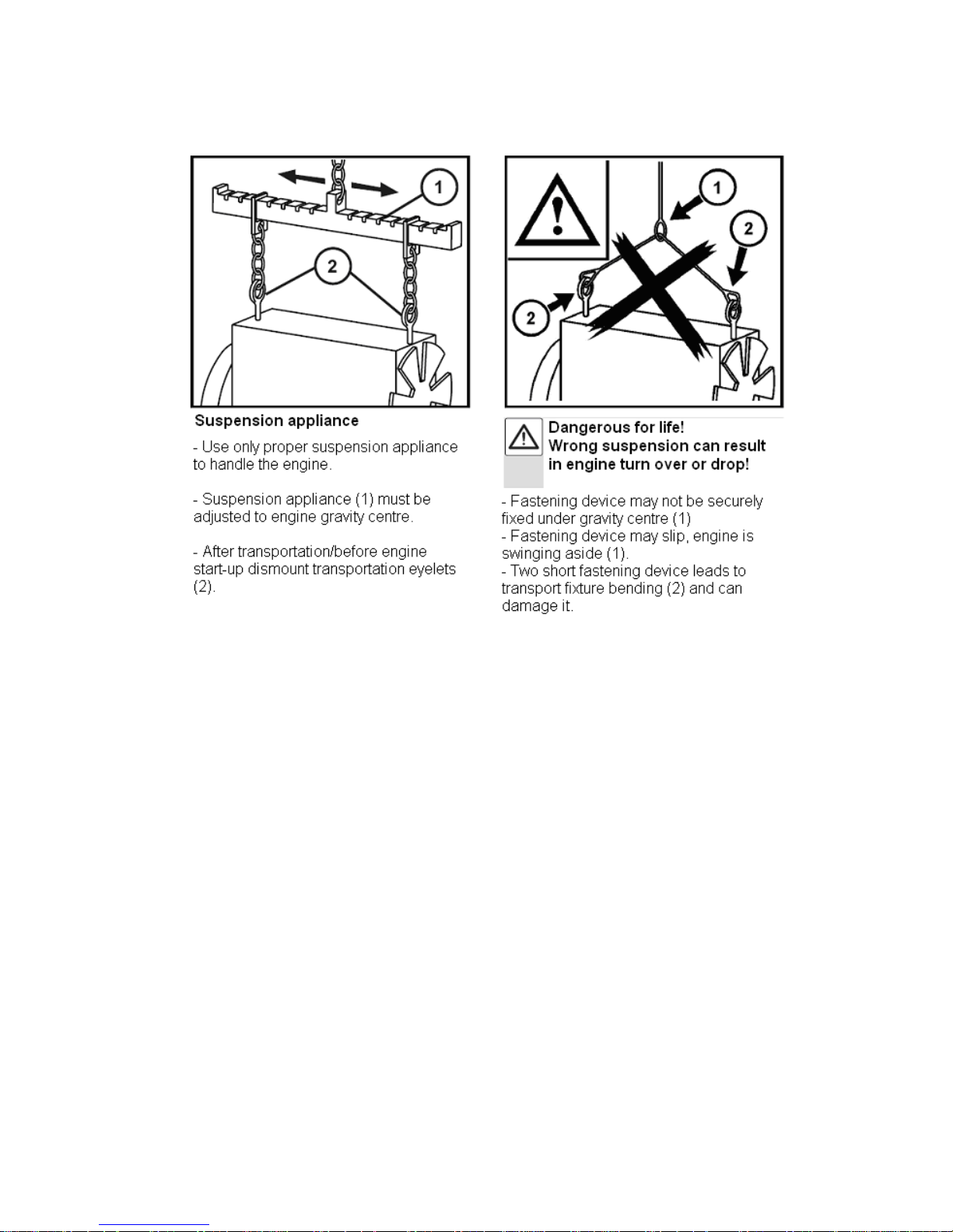
o) connect lifting mechanism to diesel, for slinging diagram see (Figures 3.5);
1 – eye bolt; 2 –steel rope (chain); 3 – beam; 4 – grip;
Figure 3.5 Diagram of slinging diesel MMZ
Disassembly-assembly manual for tractor BELARUS-1221.2/1221В.2/1221.3/1221.4
16
p) separate front driving axle together with spars and radiators from tractor and roll it away from
diesel;
ATTENTION! To prevent turning over of front axle take off ballast loads or put supports under
them.
q) unscrew bolts 10, 11 (Figure 3.1) that fasten rear diesel sheet to clutch body, disconnect diesel
having pulled it forward until clutch coupling goes out of clutch body bell, and raise it using lifting
mechanism;
Make assembly in reverse order, having fulfilled the following requirements:
Torques for threaded connections that are not given correspond to class II under Industry
Standard STP 212-2226-2006.
Before mounting the engine make adjustment of clutch, see section 4.3.2 “Disassembly-assembly
of clutch coupling’”;
After installation of engine on tractor torque:
а) torque bolts 4, 6, 7 (Figure 3.1) for fastening semi-frame 1523-2800010-01 to clutch body 80-
1601015 to 160...200 N·m;
b) torque bolts 10, 11 (Figure 3.1) for fastening rear engine sheet to clutch body to 70...80 N·m;
c) torque bolts 8 (Figure 3.1) for fastening engine to 160...200 N·m.
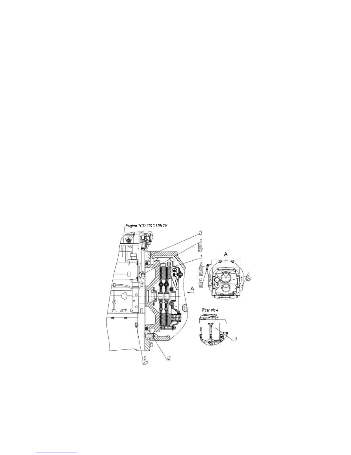
Dismounting-mounting engine Deutz, mounted on tractors BELARUS 1221.4
Figure 3.6 Mounting engine (Deutz) on tractor BELARUS 1221.4
Disassembly-assembly manual for tractor BELARUS-1221.2/1221В.2/1221.3/1221.4
17
а) Dismantle tractor facia, see section 8.3 “Dismounting-mounting facia of tractor BELARUS
1221.3/1221.4”;
b) drain cooling fluid from tractor cooling system;
c) drain oil from engine, having unscrewed plug in lower section of engine casing;
d) drain oil from HSC system, see section 7.1.1 “Disassembly-assembly of hydrostatic steering
controlunits mounted on tractors BELARUS 1221.4 with engine Deutz”;
e) loosen silicon branch pipes of supercharged air cooler , as described in section 3.4 –
“Dismounting supercharged air cooler (SAC), mounted on tractors BELARUS 1221.4 with engine
Deutz”;
е) dismount engine harness, see sections:
11.8.1 “Operations performed when replacing engine”;
11.9.1 “Operations performed when replacing engine”;
f) disconnect water radiator branch pipes from engine, as described in section 3.6 “Dismounting-
mounting cooling system mounted on tractors BELARUS 1221.4 with engine Deutz”;
g) disconnect condenser and drive of air conditioner compressor (depending on configuration),
see section 8.8 “Dismounting-mounting air conditioner (optional) on tractors BELARUS
1221.3/1221.4”;
h) dismantle outlet pipe, as described in section 3.11”Disassembly-assembly of exhaust system of
tractors BELARUS 1221.4”;
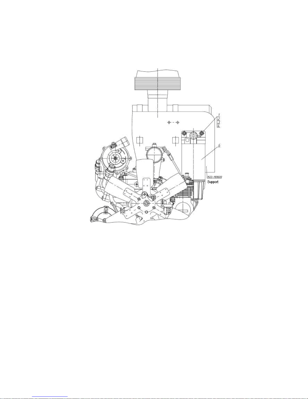
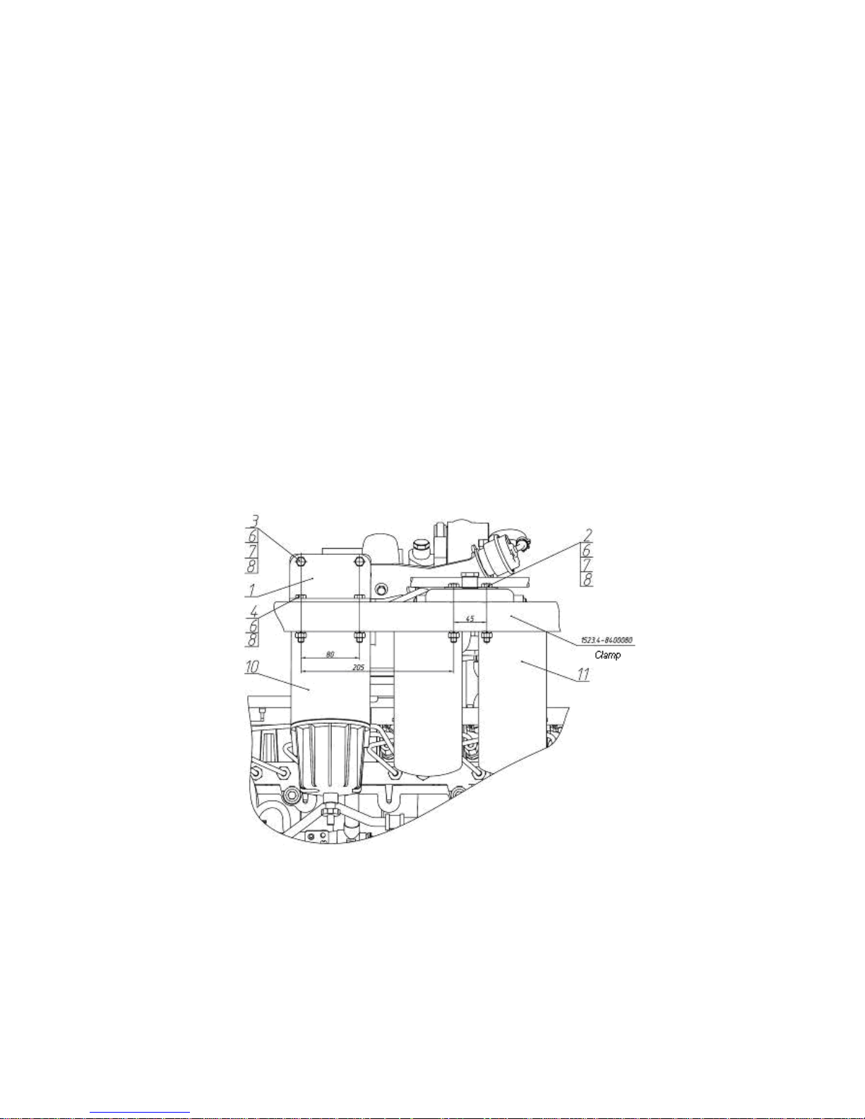
j) disconnect fuel lines from coarse fuel filter 10 (Figure 3.7);
1-arm; 2, 3, 4-bolts; 10- coarse fuel filter; 11- double fine fuel filter.
Figure 3.7 Installation of coarse and fine fuel filters on Deutz
Disassembly-assembly manual for tractor BELARUS-1221.2/1221В.2/1221.3/1221.4
18
i) dismantle air purifier, as described in section 3.10 “Disassembly-assembly of air purifier unit
mounted on tractors BELARUS 1221.4 Deutz”;
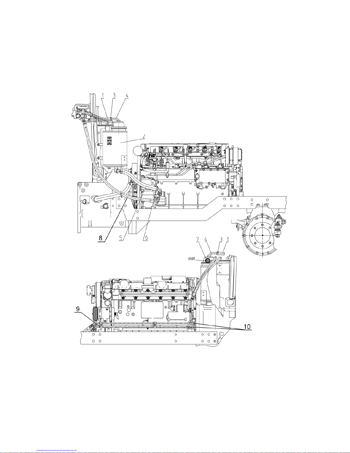
l) dismantle HSC oil lines 8, 5 (Figure 3.8) and undock from engine oil lines 10 by dismounting
brace 9;
Figure 3.8 HSC Deutz
m) dismantle cardan shaft of FDA drive;
n) connect lifting mechanism to diesel, for slinging diagram see (Figure 3.9);
o) disconnect front bar from engine, as described in section 10.3 “Disconnecting front bar from
engine Deutz”;
Disassembly-assembly manual for tractor BELARUS-1221.2/1221В.2/1221.3/1221.4
19
Figure 3.9 Diagram of slinging engine Deutz
р) undock FDA with front bar and radiators from tractor, and roll it aside from diesel;
ATTENTION! To prevent FDA turning over remove ballast loads or put supports under them.
q) unscrew bolts (Figure 3.6) that fasten rear diesel sheet to clutch body, disconnect diesel having
pulled it forward until clutch coupling goes out of clutch body bell, and raise it using lifting
mechanism;
Make assembly in reverse order, having fulfilled the following requirements:
а) torque threaded connections of bolts 5 and 6 (Figure 3.6) to 350…380 N·m;
b) torque threaded connections 9 (Figure 3.6) to 220…250 N·m;
c) torque threaded connections 8 (Figure 3.6) to 160…200 N·m;
d) Torques for threaded connections that are not given correspond to class II under Industry
Standard STP 212-2226-2006
Disassembly-assembly manual for tractor BELARUS-1221.2/1221В.2/1221.3/1221.4
20
3.2 Dismounting of supercharged air cooler (SAC), mounted on tractors BELARUS-1221.3
а) loosen collars 2 (Figure 3.10) and shift heat-resistant silicon branch pipes 3 off air conduits 1
and cooler 8;
b) unscrew bolts 4, 5, 7 that fasten cooler to water radiator and air conduit to inlet collector,
remove cooler, air conduit and spacer 6.
Make mounting in reverse sequence.
Figure 3.10
Disassembly-assembly manual for tractor BELARUS-1221.2/1221В.2/1221.3/1221.4
21
3.3 Dismounting of supercharged air cooler (SAC), mounted on tractors BELARUS-1221.4
with engine MMZ
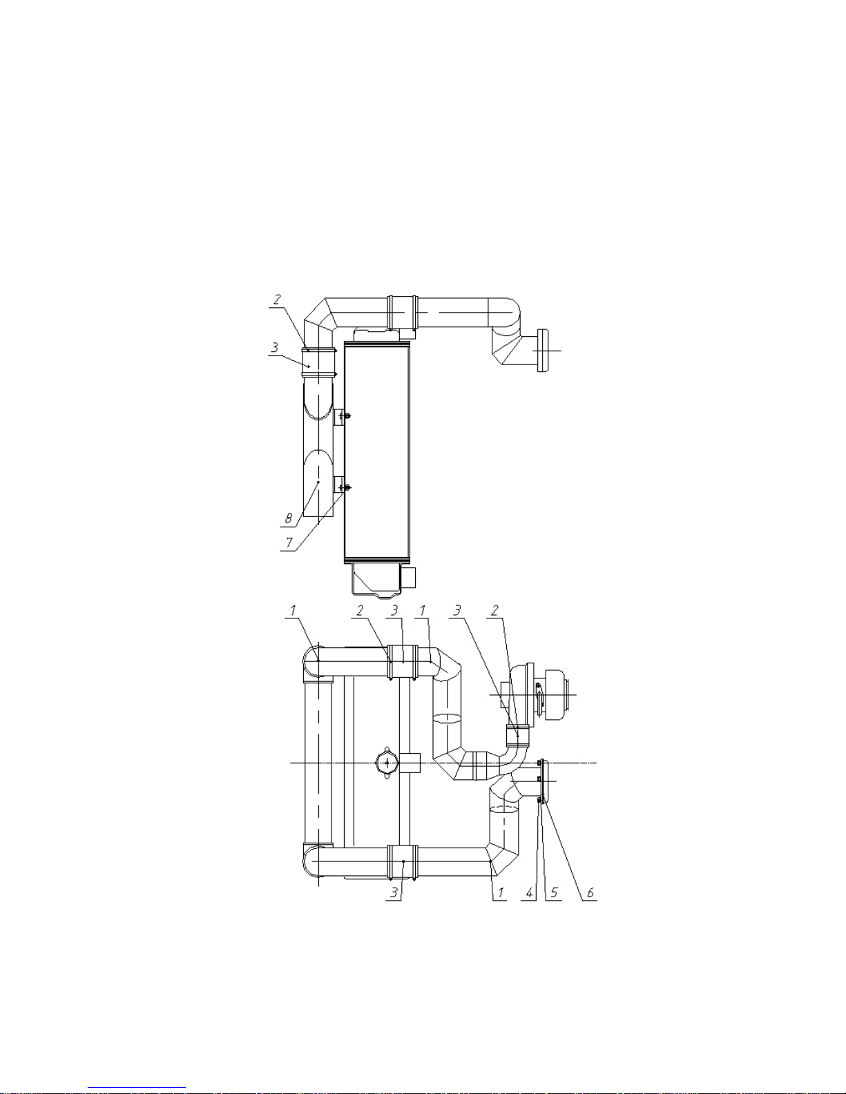
а) loosen collars 10, 11, 12 (Figure 3.11);
b) shift heat-resistant silicon branch pipes 13, 14, 15, 16 off air conduits 1, 2, 3 and supercharged
air cooler 9;
c) unscrew bolts 5 that fasten supercharged air cooler to water radiator and dismantle the cooler.
Make mounting in reverse sequence
1, 2, 3 – air conduit; 5 – bolt; 6 – nut; 7 – washer; 8 – plug; 9 – supercharged air cooler; 10, 11, 12
– collars; 13, 14, 15, 16 – silicon branch pipes.
Figure 3.11 Supercharged air cooler.
Disassembly-assembly manual for tractor BELARUS-1221.2/1221В.2/1221.3/1221.4
22
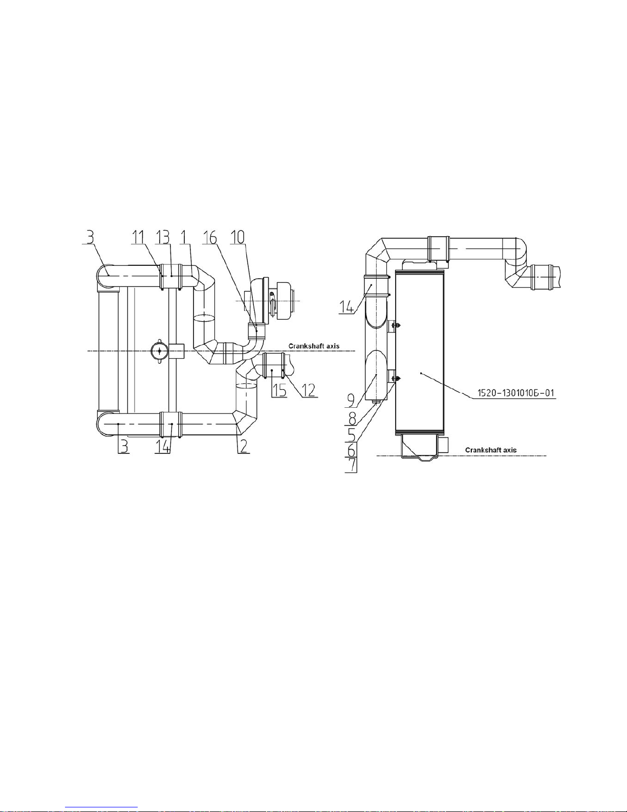
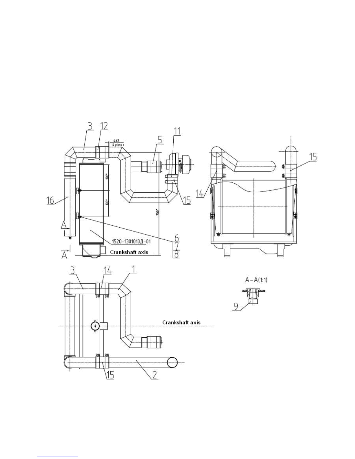
3.4 Dismounting of supercharged air cooler (SAC), mounted on tractors BELARUS-1221.4
with engine Deutz
а) loosen collars 12 (Figure 3.12) and shift heat-resistant silicon branch pipes 5, 14, 15 off air
conduits 1, 2, 3 and supercharged air cooler 16;
b) unscrew bolts fastening the cooler to water radiator and dismantle the cooler.
Make mounting in reverse sequence.
Figure 3.12
Disassembly-assembly manual for tractor BELARUS-1221.2/1221В.2/1221.3/1221.4
23
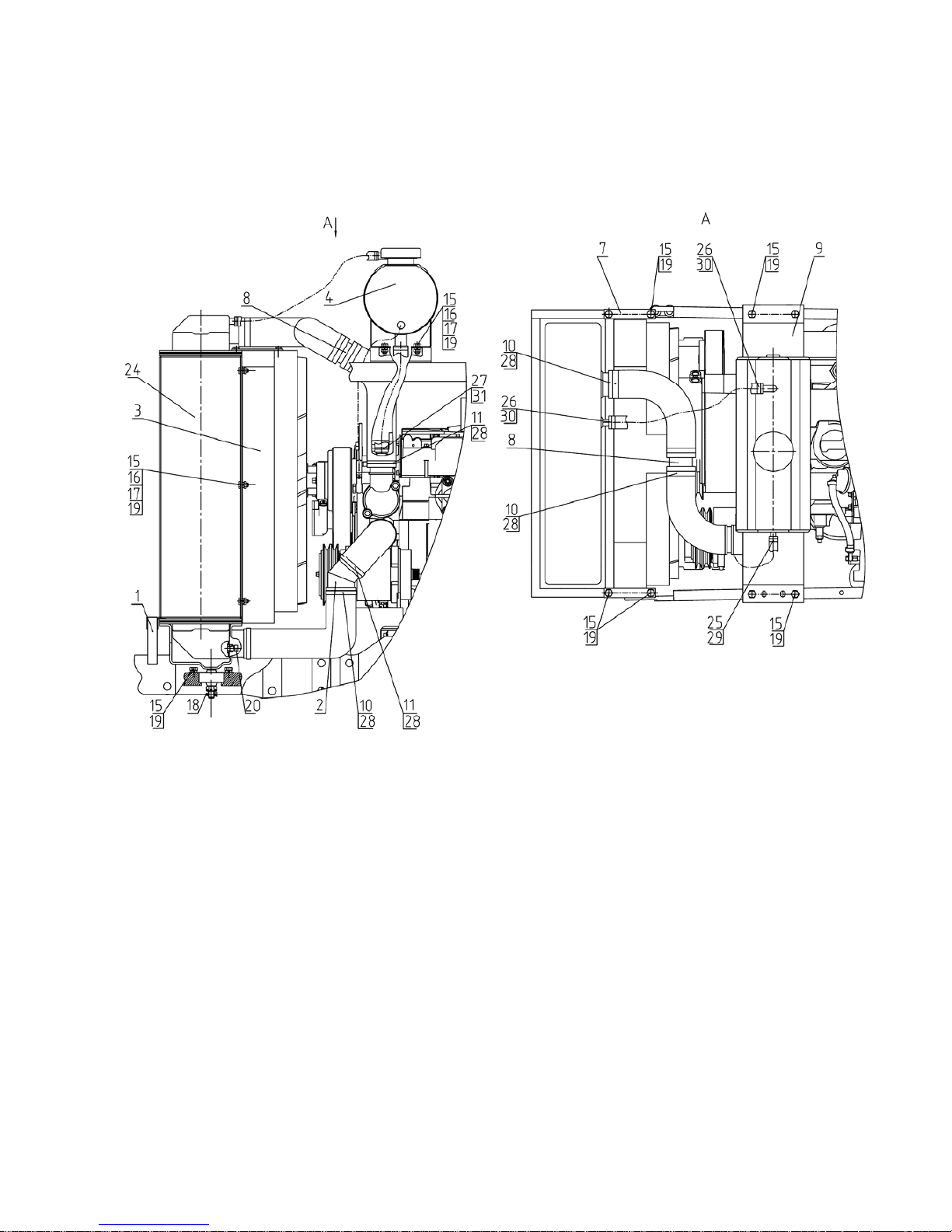
3.5 Dismounting-mounting of cooling system mounted on tractors BELARUS-1221.4 with
engine MMZ
а) drain cooling fluid from tractor cooling system;
b) untignten collars 2 (Figure 3.13) and disconnect hoses 7, 8;
c) unscrew three bolts 18, 21 and dismantle expansion tank 14;
d) dismantle SAC, as described in section 3.3 “Dismounting supercharged air cooler (SAC),
mounted on tractors BELARUS-1221.4 with engine MMZ”;
e) disconnect wires of terminal carrier socket, if installed, on fan diffuser 1;
f) unscrew six bolts 19 of fan diffuser 1 and disconnect diffuser;
g) disconnect arm 3 from engine and arm 6 from radiator 29;
h) extract extension 4 with arms 3 and 6;
j) unpin and unscrew two crown nuts that fasten radiator 25.
1, 2, 3, 4 – sealant; 5 – fan housing; 8 – arm; 9 – extension; 10, 11 – arm; 12 – collar; 13 –
bushing; 14 – plate; 15 – dish; 16 – expansion tank; 17 – plug; 18 – shock absorber; 20, 21 – hose;
22 – pipe; 23 – spring; 24, 25, 27, 28 – bolt;, 29 – screw; 30, 31 – nut; 33, 36, 37 – washer; 35 –
cotter pin; 38 – plug; 39, 40 – collar “Norma” TORRO; 42 – water radiator; 43 – sleeve.
Figure 3.13 Mounting water radiator
Disassembly-assembly manual for tractor BELARUS-1221.2/1221В.2/1221.3/1221.4
24
3.6 Dismounting-mounting of cooling system mounted on tractors BELARUS-1221.4 with
engine Deutz
Figure 3.14 Cooling system
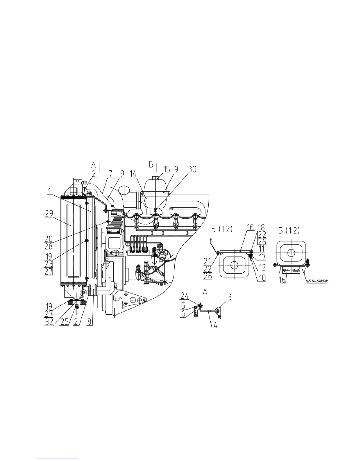
a) drain cooling fluid from tractor cooling system;
b) disconnect hose 10, sleeves 29, 30, 31 from radiator 24 (Figure 3.14);
c) unscrew two bolts 15 and dismantle expansion tank 4;
d) dismantle SAC, see section 3.4 “Dismounting supercharged air cooler (SAC), mounted on
tractors BELARUS-1221.4 with engine Deutz”;
e) disconnect sealant 1 from radiator 24, having unscrewed four nuts;
f) disconnect wires of terminal carrier socket, if installed, on fan diffuser;
g) unscrew four bolts 15 of fan diffuser 3 and disconnect diffuser;
h) disconnect plates 7, connecting radiator 24 with hood frame;
j) unpin cotter pins 18 and unscrew two crown nuts for fastening radiator;
i) dismantle radiator 24;
Disassembly-assembly manual for tractor BELARUS-1221.2/1221В.2/1221.3/1221.4
25
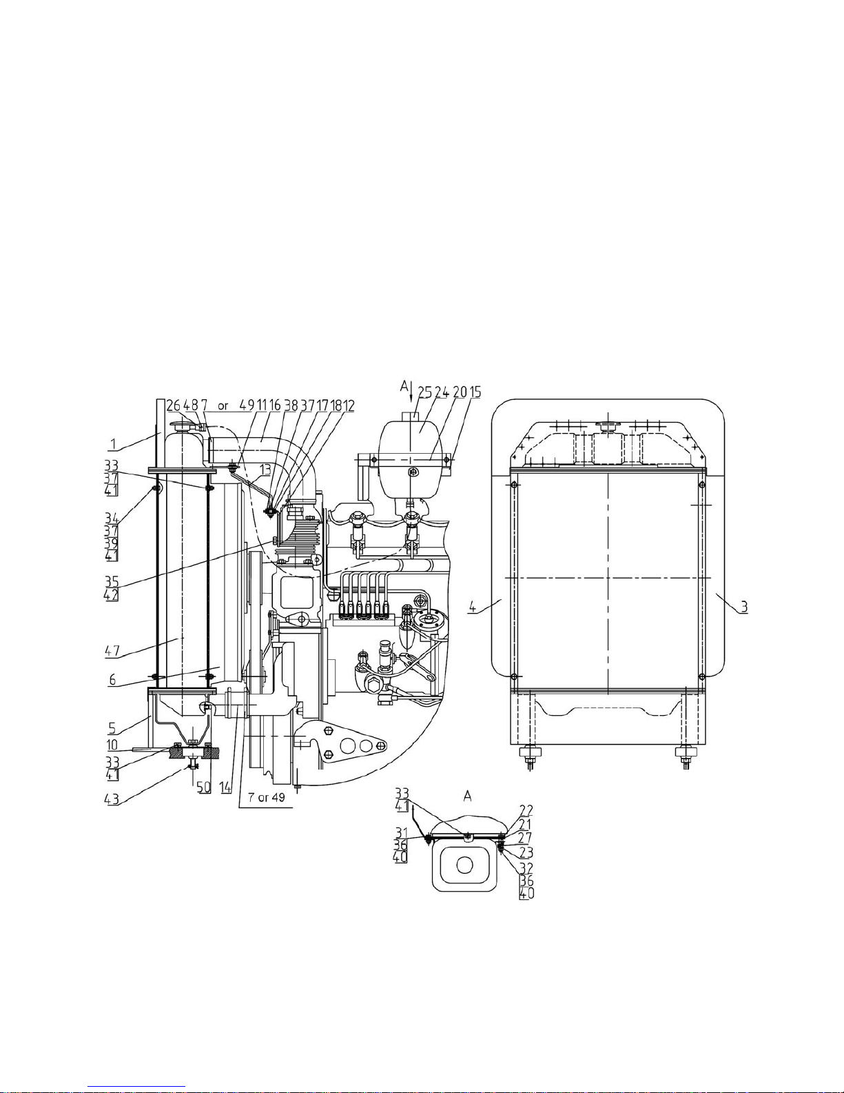
3.7 Dismounting-mounting of cooling system mounted on tractors BELARUS-
1221.2/1221В.2/1221.3 with engine MMZ
а) drain cooling fluid from tractor cooling system;
b) untighten collars 7 (Figure 3.15) or 49, 48 and disconnect hoses 14, 16, 26;
c) unscrew three bolts 31, 32, 33 and dismantle expansion tank ок 24;
d) disconnect wires of terminal carrier socket, if installed, on fan diffuser 6;
e) disconnect arm 12 from engine and arm 11 from radiator 47;
f) extract extension 13 with arms 11, 12;
g) unscrew four bolts 33 of fan diffuser 6 and disconnect diffuser;
h) unpin and unscrew two crown nuts for fastening radiator 47;
j) dismantle radiator with sealants 1, 3, 4, 5;
i) disconnect sealant 1, 3, 4, 5 from radiator 47, having unscrewd four nuts.
Figure 3.15 Cooling system

Disassembly-assembly manual for tractor BELARUS-1221.2/1221В.2/1221.3/1221.4
26
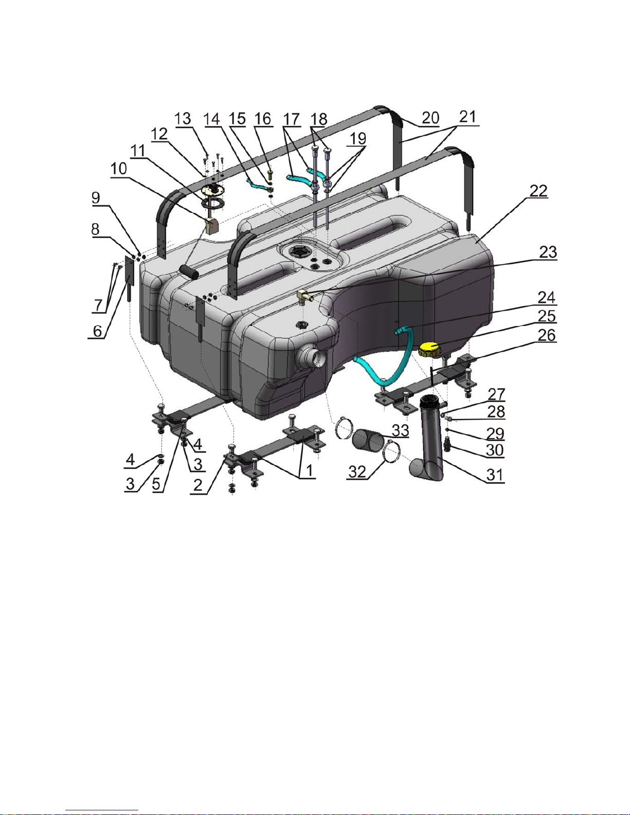
3.8 Disassembly-assembly of fuel tank 1221-1101500, mounted on tractors BELARUS-
1221.2/1221В.2/1221.3/1221.4 with engines MMZ and Deutz, with two cylinders of lift linkage
(hydraulic lift of the hydraulic system)
1) drain diesel fuel out of tank 22 (Figure 3.16) via draing point 30;
2) dismantle draining point 30;
3) dismantle ball 29;
4) dismount tractor rear left-side wheel;
5) remove cover (plug) 25 of fuel tank;
6) remove chain 26;
7) unscrew bolt 28 for fastening neck 31;
8) unscrew collars 32;
9) dismantle pipe 24;
10) dismantle neck 31;
11) remove collars 32 and branch pipe 33;
12) dismantle angle 23;
13) dismantle fuel intake 18;
14) remove washers (19) and fuel line 17;
15) dismantle point bolt 16;
16) remove washers 15 and fuel line 14;
17) unscrew nuts 3 fastening collars 21;
18) dismantle collar 21, remove sealant 20 from it;
19) unscrew screws 7;
20) remove collars 6;
21) dismantle fuel tank 22;
22) unscrew screws 13;
23) dismantle fuel sensor 10;
24) unscrew bolts 5 fastening arms 2;
25) dismantle arms 2;
26) remove rubber profiles 1 from arms 2.
Perform assembly in reverse sequence.
NOTE: When mounting fuel intakes 16, 18 and 23, grease threaded section with sealant.
Disassembly-assembly manual for tractor BELARUS-1221.2/1221В.2/1221.3/1221.4
27
Figure 3.16 Fuel tank
Disassembly-assembly manual for tractor BELARUS-1221.2/1221В.2/1221.3/1221.4
28
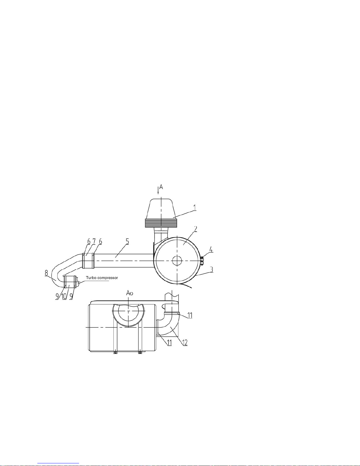
3.9 Disassembly-assembly of air purifier unit mounted on tractors BELARUS-
1221.2/1221В.2/1221.3/1221.4 (MMZ)
а) dismount facia, as described in in section 8.3 “Dismounting-mounting facia of tractors
BELARUS-1221.3/1221.4”;
b) loosen collars 6 and 9 (Figure 3.17);
c) dismantle branch pipes 7, 10 and air conduit 8;
d) loosen collars 11;
e) dismantle branch pipe 12 and air conduit 5;
f) unscrew bolts 4;
g) loosen fastening collars 3;
h) dismantle monocyclone 1;
i) dismantle air filter 2;
j) dismantle fastening collar 3.
Make assembly of air purifier in reverse sequence.
1- monocyclone; 2 – air filter; 3 – fastening collar; 4 - bolt; 5, 8 – air conduits;
6, 9, 11 – branch pipes; 7, 10, 12 – branch pipes.
Figure 3.17 Mounting air purifier
Disassembly-assembly manual for tractor BELARUS-1221.2/1221В.2/1221.3/1221.4
29
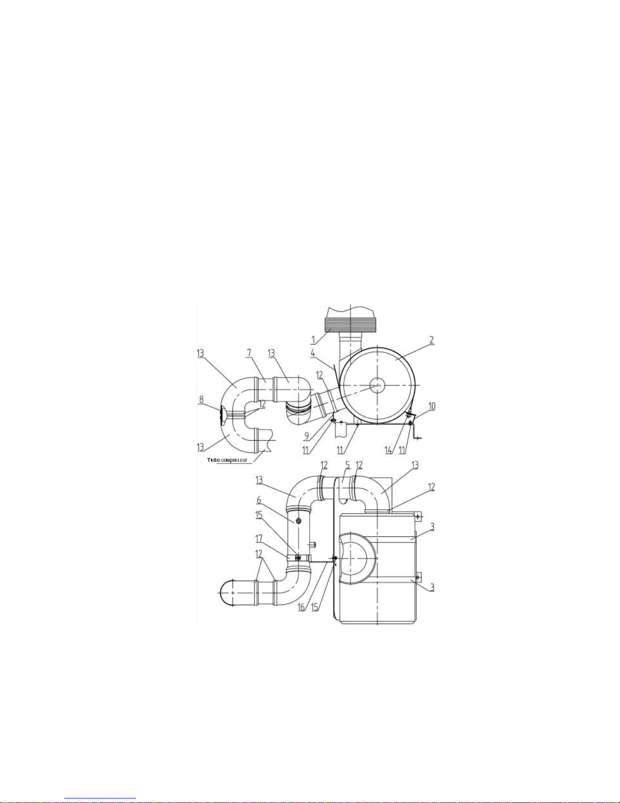
3.10 Disassembly-assembly of air purifier unit mounted on tractors BELARUS-1221.4 Deutz
а) dismount facia, as described in in section 8.3 “Dismounting-mounting of facia of tractors
BELARUS-1221.3/1221.4”;
b) unscrew bolts 15 (Figure 3.18);
c) dismantle arms 16, 17;
d) loosen collars 12;
e) dismantle branch pipes 13 and air conduits 5, 6, 7, 8;
f) unscrew nuts 14;
g) dismantle fastening collar 3, monocycle 1 and air filter 2;
h) unscrew bolts 11;
i) dismantle arms 4, 9, 10;
Make assembly of air purifier in reverse sequence.
1- monocyclone; 2 – air filter; 3 – fastening collar; 4, 9, 10, 16, 17 - arms;
5, 6, 7, 8 – air conduits; 11, 15 – bolts, 12 – collars; 13 – branch pipes; 14 - nuts.
Figure 3.18 Mounting air purifier
 Loading...