

MINSK D-260.1S3, D-260.2S3, D-260.4S3, D-260.1S3A, D-260.2S3A Maintance Manual
...
Open Joint Stock Company
"MINSK MOTOR PLANT" Holding Managing Company"
Diesel engines
D-260.1S3А, D-260.2S3А, D-260.4S3А
OPERATION & MAI NTENANCE MANUAL
Minsk 2013

TABLE OF CONTENTS
1 DESCRIPTION AND OPERATION .....................................................................................................................................................4
1.1 DIESEL ENGINE DESCRIPTION AND OPERATION .......................................... ERROR! BOOKMARK NOT DEFINED.
1.1.1 Diesel engine application .......................................................................................... Error! Bookmark not defined.
1.1.2 Technical specifications ............................................................................................ Error! Bookmark not defined.
1.1.3 Diesel engine components ......................................................................................... Error! Bookmark not defined.
1.1.4 Design and operation ................................................................................................ Error! Bookmark not defined.
1.1.5 Diesel engine labelling ............................................................................................................................................ 14
1.1.6 Packaging ................................................................................................................. Error! Bookmark not defined.
1.2 DESCRIPTION AND OPERATION OF DIESEL ENGINE COMPONENTS, MECHANISMS AND DEVICES .. ERROR! BOOKMARK NOT
DEFINED
.
1.2.1 General information ................................................................................................. Error! Bookmark not defined.
1.2.2 Description and operation ......................................................................................... Error! Bookmark not defined.
1.2.3 Diesel engine labelling and sealing ......................................................................................................................... 42
2 APPROPRIATE USE ............................................................................................................................................................................ 42
2.1 OPERATING RESTRICTIONS ............................................................................................................................................... 42
2.2 DIESEL ENGINE PREPARING FOR OPERATION ..................................................................................................................... 43
2.2.1 Safety rules to be observed while preparing diesel engine for operation ............................................................... 43
2.2.2 Diesel engine, its assembly units and parts depreservation ................................................................................... 43
2.2.3 Diesel engine additional equipment ........................................................................................................................ 44
2.2.4 Filling the cooling system ........................................................................................................................................ 44
2.2.5 Filling the engine with fuel and oil .......................................................................................................................... 45
2.2.6 Diesel engine controls and control devices ............................................................................................................. 45
2.3 DIESEL ENGINE USE .......................................................................................................................................................... 45
2.3.1 The order of diesel engine use by authorized technical personnel ......................................................................... 46
2.3.2 Diesel ngine start ..................................................................................................................................................... 46
2.3.3 Diesel engine shutdown ........................................................................................................................................... 47
2.3.4 Diesel engineoperationsl run-in .............................................................................................................................. 47
2.3.5 Diesel engine operation in winter conditions .......................................................................................................... 47
2.3.6 Possible failures and troubleshooting .................................................................................................................... 48
2.3.7 Safety measures with engine appropriate use ........................................................................................................ 121
2.4 OPERATION IN EXTREME CONDITIONS ............................................................................................................................ 121
3 MAINTENANCE ................................................................................................................................................................................. 122
3.1 DIESEL ENGINE MAINTENANCE ....................................................................................................................................... 122
3.1.1 General instructions .............................................................................................................................................. 122
3.1.2 Safety measures ..................................................................................................................................................... 124
3.1.3 Maintenance procedures ....................................................................................................................................... 125
3.1.4 Checking the engine operation condition .............................................................................................................. 126
3.1.5 Proofing (reproofing) for storage .......................................................................................................................... 127
3.2 DIESEL ENGINE AND ITS COMPONENTS MAINTENANCE ........................................................................................... 130
3.2.1 Checking the cooling liquid level in the cooling system ........................................................................................ 130
3.2.2 Cooling system maintenance and washing ............................................................................................................ 130
3.2.3 Checking oil level in the engine oil sump .............................................................................................................. 130
3.2.4 Replacing oil in the engine oil sump ...................................................................................................................... 131
3.2.5 Replacing he oil filter ........................................................................................................................................... 131
3.2.6 Cleaning the centrifugal oil filter rotor ................................................................................................................. 132
3.2.7 Sediment removal from fuel pre-filter .................................................................................................................... 133
3.2.8 Replacing fuel pre-filter ......................................................................................................................................... 133
3.2.9 Replacing fine fuel filter ........................................................................................................................................ 133
3.2.10 Заполнение топливной системы ...................................................................................................................... 134
3.2.11 Servicing the air cleaner ...................................................................................................................................... 135
3.2.12 Checking the air cleaner and the inlet duct connections hermeticity .................................................................. 136
............................................................................................................................................ Error! Bookmark not defined.
3.2.13 Washing the engine breathers ............................................................................................................................. 136
3.2.14 Tightening the cylinder heads bolts ..................................................................................................................... 137
3.2.15 Checking the gaps between the valves and the rockers ....................................................................................... 137
3.2.16 The “COMMON RAIL” system maintenance ...................................................................................................... 138
3.2.17 Alternator maintenance ...................................................................................................................................... 139
3.2.18 Checking the belts tension ................................................................................................................................... 139
3.2.19 Checking the starter motor condition ................................................................................................................. 140
3.2.20 Turbocharger maintenance ................................................................................................................................. 140
3.2.21 Compressor maintenance .................................................................................................................................... 141
3.2.22 Gas exchange system components maintenance ............................................................................................... 141
4 CURRENT REPAIR ............................................................................................................................................................................ 141
4.1ENGINE CURRENT REPAIR ................................................................................................................................................ 141

4.1.1 General instructions ............................................................................................................................................. 141
4.1.2 Safety measures..................................................................................................................................................... 143
4.2 ENGINE COMPONENTS CURRENT REPAIR ......................................................................................................... 144
4.2.1 General instructions on piston rings replacement ................................................................................................ 145
4.2.2 General instructions on the valves grinding ......................................................................................................... 146
4.2.3 General instructions on water pump disassembly and assembly .......................................................................... 147
5 STORAGE ............................................................................................................................................................................................ 149
6 TRANSPORTATION .......................................................................................................................................................................... 150
7 RECYCLING ....................................................................................................................................................................................... 150
Annex А(reference) ........................................................................................................................................................ 151
Chemmotological chart ....................................................................................................... Error! Bookmark not defined.
Annex Б (reference) ....................................................................................................................................................... 155
Spare Parts & Accessories ............................................................................................................................................ 155
Annex В (reference) ....................................................................................................................................................... 156
Cylinder liners and pistons size groups ......................................................................................................................... 156
Crankshaft main end and big end necks nominal sizes
Synchronization of the crankshaft and the HPFIP camshaft angle position.................................................................. 158
Annex Е (reference) Diesel engine electronics structural electric d iagram ................................................................. 162
Annex Е (reference) ....................................................................................................................................................... 163
Annex Е(reference) ........................................................................................................................................................ 164
Annex Ж ......................................................................................................................................................................... 165
Diesel engine and turbocharger failures identification ..................................................... Error! Bookmark not defined.
Annex И (reference) ....................................................................................................................................................... 166
Engine slinging scheme ...................................................................................................... Error! Bookmark not defined.

This Manual is intended for use by operators, drivers and engine mec hanics of agricultural tractors, combine h arvesters and agricultural machinery e quipped with diesel engines D-260.1S3A, D-260.2S3A, D -260.4 S3A as well as by personnel of technical service
centres and repair shops pe rforming technical service and repair of said diesel engines.
This Operation & Maintenance Manual c ontains brief technical description, diesel engines operation and technical maintenance rules.
Eligible to diesel engines operation and technical m aintenance rules are individuals with
special traini ng an d t hose hav i ng re ad thi s Oper at ion & Maintenance Man u al.
Diesel engines a nd th eir components curre nt re pair may be done by mechanics familiar
with their design, principle of operation, having general technic al background according
to 3-4 grades training programme.
Diagnostic s and tec h nic a l serv ice of Common Rail fuel system m us t be done by spe c iall y
trained personnel using specialised diagnostic equipment.
Diesel engines design im plies long operation life without complete overhaul, provided the
rules of operation, storage and timely technical service described in this Manual are observed.
Diesel engines exhaust gases contain substances harmful to human health (nitrogen oxides, carbon oxides, hydrocarbo ns, ha rd pa rt ic les ).
Applied in diese l eng i nes de si gn are tech n i cal s olut i on s al low in g to red uc e the h arm ful
substances impact on human health and environment, so unauthorized modification of the
engines design, breaking the manufacturer settings, disregard ing technical service periodicity is strictly forbidden.
The rooms where diesel engines are run must have purge-exhaust ventilation and the engine exhaust system must h av e an autonomous gas diversion duct from the engine si lencer to the outside of the room.
Due to the eng ines continuous development, some of their assembly units and parts may
be subject to modifications not indicated in this Operation & Maintenance Manual.
Customers’ disregarding the rules and conditions of operation, technical service, transportation and storage contained in this Manual, breaking the manufacturer
seals as well as using in current repair and technical service consumables (fuel and lubrication mate ri a ls, a ssembly units and par ts) fr om ma nu f act urers not recommend ed f or
use by the OJSC "MMP " HMC " desi gn d oc um en ta tio n, eng in e desi gn mod if ic at i on wil l
stop the engine warranty validity.
Engine and (or) its com p one n ts re pai r by the owne r o r othe r pe rso ns w ith ou t
participation of the manufacturer specialists or its authorized dealer centre in t he eve nt
of the engine failure within the warranty period will make the engine or its components
warranty inva li d.

1. ENGINE DESCRIPTION AND OPERATION
1.1. Diesel engine descri ption and operation
1.1.1 Diesel engine application
Diesel engines applicat ion, applicat ion environment and operation condition s are shown
in table 1.
Table 1
Description
Engine model
D-260.1S3A D-260.2S3A D-260.4 S3A
Application
Wheeled tract ors, 1,4 ; 2 draw ba r
categories
Forage harve sters and wheeled
tractors, 3; 4 drawbar categories
Application
environment
Areas with unlimited air exchange
Climatic
conditions of
operation
Microclimatic regions w ith moderate climate. Air temperatu re va lues
of operation conditions fr om + 40º С to - 45º С.*
Microclimatic regions w ith both dry and humid tropic al climate. Air
temperature values of oper ation conditions from + 50º С to - 10º С.
*- with diesel engine operation at the environment temperature lower than -25ºС the
coarse fuel f ilter must be eq uipped with a fuel heater.

1.1.2 Technical spec ifications
Diesel engines tech ni cal s pec if ic at io ns an d oper at ion pa r am ete r s
Table 2
Parameters Measurement unit
Engine model
D-260.1S3A
D-260.2S3A
D-260.4 S3A
Values
Diesel engine type 4-stroke, turbocharged with charge air cooling
Fuel mixture method Volumetric fuel mixture formation
Number of cylinders
pcs
6
Positioning of cylinders
In-line, vertical
Swept volume
litres
7,12
Firing sequence
1-5-3-6-2-4
Crankshaft rotation direction per State Standard
22836-77 (from the fan side)
Right (clockwise)
Bore
mm
110
Stroke
mm
125
Compression ratio (calculated)
17
Permissible inclination angles at engine operation -
- longitudinal
- Transverse
degrees
20
20
Operating output
kW
111,0
96,9
148,6
Rated speed
min
2100
Specific fuel consumption at operating output
g/ kW/ hour
249,0
Maximal torque
Nm
660,0
570,0
923,0
Speed at maximal torque, not less than
min1
1600
Engine mass without fuel, lubricants and coolant
(with fan, alternator, starter and air cleaner)
kg 710 750
Average noise level. Not more than
dBA
97
98
General logarithmic levels of vibration velocity,
not higher than
а) vertically
dB
108,2
б) horozontally
110,2

1.1.2.2 Controlled engine parameters
Table 3
Parameters
Measurement unit
Engine model
D-260.1S3A
D-260.2S3A
D-260.4 S3A
Value ± confidence limit (tolerance)
Rated output
kW
116,0±2,0
100,0±2,0
156,0±3,0
Rated speed
min1−
2100
4025+
−
Specific fuel consumption at rated output
g/ kW/ hour
240,0
0,
12
2,7
+
−
Minimal stable idling speed
min1−
800±50
Maximal stable idling speed limited by regulator, not higher than
min1−
2270 2270 (2250**)
Oil pressure in the main lubrication system line:
-at rated speed
-at minimal speed
MPa
0,28…0,45
0,10
0,16
Note:
* The parameters are reached afte r 60 hours of engine operation with the counter-pressure of not less than 150 kPa at a distance of 200 mm
from the exhaust duct measured from the turbocharger flange with the engine brake switched off, the fuel temperature at the fuel system inlet
between 38º С and 43º С and reference atmospheric conditions per UN EEC Rules No 24(03)/ 2nd Revision:
-atmospheric pres su re - 100 kPa
-water vapours press ure - 1 kPa
-air temperature - 25º С;
The parameters are calculated wi th formuli per State Standard 18509-88.
** For combine harvester diesel engines

1.1.2.3 Measuring means for dete rmining the controlled parameters
Table 4
Measured parameter
Measurement
unit
Measurement means
Measurement means basic ab-
solute error limit
Note
Torque
Nm
Strain and torque strength measuring
devices according to State Standa rd
15077-78
±0,005Мк max
For rated output
calculation
Speed
min
1−
Electronic tachometers, ТЭСА type
according to Technical Conditions 25-
04.3663-78, State Standard 18303-72
±0,005n rated, but not more than 10
min-1
±0,005n rated, but not more
than 10 min-1
Oil pressure in the lubri-
cation system
MPa
Pressure gauges, compound gauges
according to State Standards 2405 -80
and 11161-84, pressure and depres-
sion measuring trans du ce rs ac c ord ing
to State Standard 22520-85
±0,02
Hourly fuel consumption kg/ hour Non-standard measuring means ±0,01Gт
For specific fuel
consumption ca l-
culation

1.1.3 Diesel eng ine parts and components
Diesel engine consists of parts, a sse mbly units and sets.
1.1.3.1 Basic D-2 60 S3A die se l eng ine ass em bly u nits
Table 5
Assembly units and sets
Cylinder block
Water catchment pipe
Cylinder heads mounting
Water pump mounting
Clutch mounting
Fan mounting
Turbocharger mounting
Tensioner mounting
Oil sump mounting
Gear pump mounting
Pump mounting
Compressor m ounting
Heat exchanger mounting
Alternator mounting
Filter mountin g
Starter motor mounting
Fuel equipment mounting
Drive and counter mounting
Oil ducts
Spare Parts, To ols & Accessories Kit

1.1.3.2 Key features of diesel engine models configurations
Table 6
Units, parts
Engine model
D-260.1S3А D-260.2S3А D-260.4S3А
Unit, part designation and (or) its description
Turbocharger
К27-61-08* "Turbo" (Czechia)
К27-542-01 "Turbo" (Czechia)
Compressor
Single cylinder air cooled, controlled * or not not available
Gear pump НШ-10 or НШ 14-3Л, or НШ 16-3Л*
High-pressure fuel injection pump
СРN2.2 ("BOSCH", Germany)
Electronic control unit
EDC7UC31 ("BOSCH", Germany)
Injector CRIN2 ("BOSCH", Germany)
Fuel pre-filter
Type Preline PL 420 ("MANN-HUMMEL GMBH", Germany) ** (with water separator and manual priming pump) or similar filter
by other manufacturers
Fine fuel filter Mann & Hummel WDK962/12 or WDK962/14 (Germany)
Air filter
With paper filter elements **
Oil filter
Non-separable, full flow, centrifugal, working on branch
Fan and fan drive
Axle type
Unavailable **

Continuation of Table 6
Units, parts
Engine model
D-260.1S3А D-260.2S3А D-260.4S3А
Unit, part designation and (or) its description
Clutch
Friction type, dry, constantly closed-type, double-disk* or single disc or not available
Friction type, dry, constantly closed-type,
double-disk
Alternator
AC, rated voltage 14V or 28V
Starter
Rated voltage 24V***
Start-up aids
Diesel engines are equipped with pin glow plugs with rated voltage of 23V and have locations for heat carriers inlet and outlet when a
pre-start heater is installed
Note
*- for tractor engine s;
**- to be installed by cust om er;
***- to be installed by customer on the engines going to MTZ t ractors;
The D-260.1S3A diesel engine appearance is shown in Fig.1.
Spare Parts, Tools & Accessories Kit list - See Annex "B" to this Manual (Table B.1)
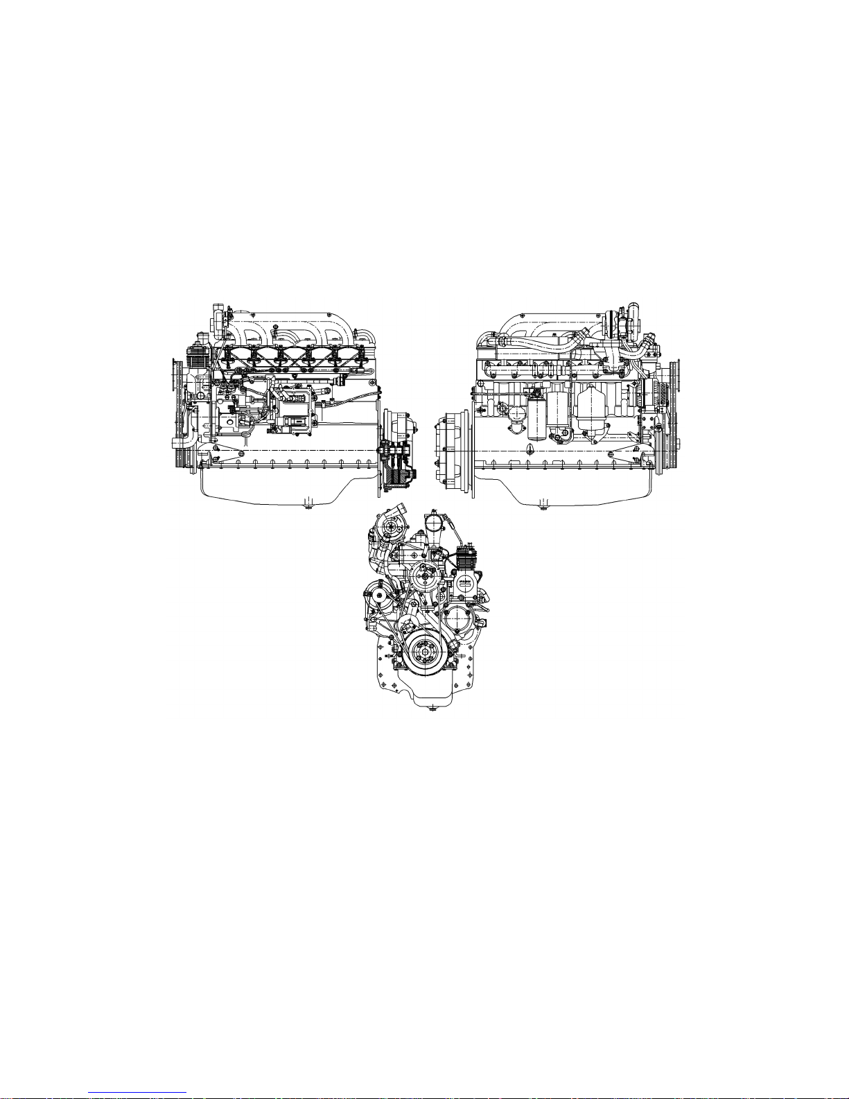
Fig.1 - Diesel engine D-260.1S3A

1.1.4 Design and operation
Engines D-260.1S3A, D-260.2S3A, D-260.4 S3A are 4-stroke intern al combustion piston diesel engines with vertical cylinder positioning, direct fuel injection and ignition by
compression.
The basic engine assembly units are: cylinder block, cylinder heads, pistons, connecting
rods, crankshaft and flywh eel.
To ensure high technical and economic characteristics the engines inlet systems use
turbo charging w ith c ha rge a ir inte rmediate coolin g.
Using turbocharger with controlled air pressure in the charging device allows better
engine pickup provided by higher torque values at low c rankshaft speeds.
Engines equipped with "Common Rail" accumulator type fuel system show higher operational and fuel economy and conform to Tier-3A ecological parameters due to optimized operation process and minimization of transitional processes while changing the
speed and load modes.
1.1.4.1 Gener al inf or mat i on
Engines D-260.1S3A, D-260.2S3A, D-260.4 S3A are 4-str oke piston internal combustion
diesel engines with vertical cylinder positioning, dire c t fue l in jec ti on and ig n it io n fro m
compression.
The basic engine assembly units are: cylinder block, cylinder heads, pistons, connecting
rods, crankshaft and flywheel.
To ensure high technical and economic characteristics the engine s inlet systems use turbo
charging with charge air intermediate cooling.
Using turbocharger with controlled air pressure in the charging device allows better engine pickup provided by higher torque v alues at low cra nkshaft speeds.
Engines equipped with "Common Rail" accumulator type fue l sy stem sh ow hi gh er op e rational and fuel economy and conform to Tier-3A ecological parameters due to optimi zed
operation process and minimization of transitional processes while changin g the speed
and load modes.
Using exhaust gas recirculat ion devices in the engines feed system also contributes to
reaching the required ec ological param eters, bringing changes into the mass charge contents enterin g the eng ine c yl i nde rs by way of par ti al de liv er of e xh au st gas.
To ensure engine start-up at low ambient t e mpe ra tu re s, glow p lug s are in st a lle d in th e
engine cylinder head, while fuel liquid heat exchange r ensures a faster reaching of the optimal oil tempera t ure in th e en gine lub ric a t ion sy s tem a nd ke e pi ng it at the req ui re d leve l
during the engine operation.

1.1.4.2 Diesel engine operation princ iple and its ba sic components interaction
A diesel engine operation principle, like with all other internal combustion e ngines, is
transformation of heat energy of the fuel burning inside in the working cylinder to m echanical energy.
When a piston moves down at th e int ake str oke th rou gh th e ope n in le t valv e a n air ch arge
comes into the cylinder. When the inlet v alve closes and the piston m oves upwards the air
compression tak e s pl ace. At this the air temperature goes up sharply. In the end of the
compression st ro ke fuel is de li ver ed th r ou gh an injector into the cyl inde r u nde r hig h pressure. While being injected, fuel is fine ly sprayed, mixed with hot air in the cylinder and
evapourated, thus making a fuel-air mixture.
The air-fuel mixture igniti on during the diesel en gi ne op er at i on is achieved as a result of
air compression to the extent of the air-fuel mixture self-ignition. The fuel is injected by
injectors with fast operating electromagnetic valves. The moment of injection beginning
and its duration are dete rm i ned by the mo m ent of be gi n ning a n d dur ati o n of vol ta ge su pply to the electromagnetic valve by the Common Rail system Electronic Control Unit. The
fuel-air mixture bur ni ng ta kes pl ace at the moment of the pisto n starting to go down.
As soon as the fuel-air mixtu re is bunt down the process of cylinder expansion and cl eaning begins through the exhaust valve.
Opening and closi n g of the intake and exhaust valves is coordinated by the gas distribution mechanism.
With the diesel engine operation start the turbocharger is actuated by the exhaust gas energy.
The diesel engine s ta rt is done by imparting rotation to the crankshaft by the electric
starter via the flywheel m ounted on the crankshaft flange.
The diesel engine co o li ng sy st em water pu m p is driv e is maintained from the belt of t he
pulley mounted on the crankshaft toe to t he pulley mou nted on the water pump shaft.
The А29.05.000 БЗА compressor drive and that of the gear pump is maintained by the
toothed transmission of the distributi on mechanism.
The transfer of energy (p ower) generated bythe diesel engine to the drive of tractor (agricultural machi ne) in whi ch it is installed is done from the engine flywhe el via the clutch.
1.1.4.3 Tool s and accessories
To ensure the maintenance work on checking and adjustin g t he gap between the rocker
striker and the valve end, done in the cou r se of tech n ic al ser vice, tools are attached according to the list in table B.2 of Annex B.
1.1.5 Diesel en gi ne la bel l in g
The brand tag of each engine fixed to the cylinder block bears the following data:
-manufacturer’s name and its trade mark;
-engine model (modification);
-engine serial pr oduc ti on n um be r;

-inscription “Made in Belarus”in the English language .
The engines officially approved according to EEC UN Rules No 96(0 1), EEC UN Rules
No 24(03), Revised Edition No 2 and Directives 2000/25/ЕС, 97/68/ЕС Stage IIIА bear
the sign of official engine type approval.
The engines for whi c h nati on a l cert if ic ate s have issu e d for c onf ormity to the rules of Belarus and other CIS countries bear the sig ns of conformity to the national certification systems of the countri es whe re th ose cer ti ficates have been issued.
The official appro va l si g ns and the si gns of conf ormity are located si de by side wi th the
brand tag or are depicted on it.
The engine transport mark ing is applied according to STATE STANDARD 14192. The
marking method e nsu res it s preservation for the period of the engine trans po rta ti o n,
storage and operation life.
1.1.6 Packaging
With the engines transportation in closed carriages, containers or by trucks the engines
are secured on wooden stands made to the manufacturer’s drawings. With shipping the
engines in open type tran sport (trucks, trains) the en gines are wrapped in polyethylene
bags according to ST A T E STA ND A RD 103 54 an d are sec u red o n woo de n sta n ds.
The engines shipped in railway carriage s to the regions with tropical climate are
wrapped in polyethylene bags and placed in wooden cases; when shi pped in sea containers - wrapped in polyethylene bags.

1.2 Description and operation of diesel engine co mponents, mechanisms
and devices
1.2.1 General information
Diesel engine is a complex unit consisting of a number of separate mechanisms, systems
and devices made of parts and units. The engine struc ture is shown in Table 7.
Table 7
Diesel engine configuration
Units and parts making mechanisms, systems and
devices
Housing
Cylinder block and suspension
Mechanisms
Gas distribution
Cylinder hea d. Valves and pushers
Cylinder hea d covers, manifold and breathers
Distribution mechanism
Crank-and-slot Pistons and conrods. Crankshaft and flywheel
Systems
Oiling
Oil sump
Oil pump rece iver and oil pump
Heat exchanger
Oil filter
Centrifuga l oil filter
Turbocharger oil ducts
Supply
Fuel piping and fuel equipment
Coarse fuel filter
Fine fuel filter
Air cleaner and air duct
Electronic
fuel supply control
Electronic Control Unit, sensors and actuating mechanisms
Cooling
Water catchment pipe and thermostats
Water pump a nd tensioner
Fan
Devices
Supercharging
Turbocharger
EGR
EGR cooler
Startup
Starter motor
Glow plugs
Drives
Electric eq uipment
Alternator
Units
Compressor
Gear pump
Clutch

1.2.2 Description and operation
1.2.2.1 Cyl ind er bl oc k
Cylinder block is the main body part of the engine ma de as a cast iron monoblock.
Placed in the monoblock bo res are six removable liner s made of special cast iron .
Liners are fitted in the cyl inder block along two center ing zones.
Each liner is fixed by a collar in the upper zone while in the lower zone it is packed with
two rubber rings placed in the cylinder block grooves.
Cooling liquid circulates between the cylinder block walls.
The cylinder block transverse dividers have pads for forming the c rankshaft supports.
Mounted on those pads are covers. The pads together with the covers shape beds for the
main end bearings. The beds for the main bearing shells are bored with one installation
complete with covers. It is not permissible to change the covers placing.
Cylinder block has a longitudinal oil channel from which oil is supplied to the crankshaft
main end bearings along transverse channels and furt her to the camshaft ends and injectors for pistons co ol ing. The inje c tors f or pistons cooling are installed in the cylinder
block, in the upper sectio n of the second, fourth and sixth cranksha ft supports
The cylinde r block water distribution channel has a floor for insta llation of liquid-oil
heat exchanger. The oil supply and dive rsion from the heat exchanger goes via the channels in the block.
To stiffen the lower surface of the cylinder block it is shif te d down to 80 mm relativ e to
the crankshaft axis. A steel distribution sh ie ld and di s tr ibu ti o n cove r are fixe d to the f ro n t
end of the cyli nder block, to the rear end - a steel plate by which the engine is connecte d
to tractor (mac h ine ) fram e. Two br ack e ts fi xed on th e cyl i nde r bloc k si de s serv e as th e
engine front support. The cylinder block bottom is covered by oil samp.
1.2.2.2 Cylinder heads
Cylinder heads are made of c ast iron (one head for three cylinders)and are mutually exchangeable. The cylinder heads inner cavities have intake and exhaust channels closed
by valves.
To divert heat from cylinder heads there a re inner cavit ies where the cooling liquid circulates. The cy l inder heads have inse rta bl e valv e sea ts ma de of he at res i st ant an d we ar
resistant allo y. Mou n ted o n the cy li nde r he ad s are in jec t or s (3 piec e s for eac h hea d),
racks, rocker axles with rockers, cylinder head covers and cover ca ps closing the v alve
mechanism. On the left side (from the fuel injection pump) there are 3 glow plugs for
each head.
As a sealing between the cylinder heads and the block an as be st os-free gasket is placed.
The holes for cylinder line rs and oil channel are edged with pltae steel. From both sides
of the gasket along the outer edge, as well as the edges of the holes located in the oiling
system and liquid cooling areas
On both sides of the gasket, along the outer edge as well as the edge s of the h ole s loc a ted
in the lubrication and liquid cooling system channel s, elastomeric sealant is applied by
screen-relief method. When assembling a diesel engine, its cylinder holes are additionally
lined with fluoroplastic rings.

1.2.2.3 Crank-and-rod mechanism
The main parts of the crank-and-rod mechanism are: crankshaft with main end and big
end bearings, flywheel, pi stons with piston rings, connection rods.
Crankshaft is made of steel, it has seven main end and six big end bearings.
To reduce the loa d de riv ed fr om ine rtia o n the be ar ing s, rem ov a ble co un te r ba lan-ces
are mounted on the 1
st
, 6th, 7th and 12th crankshaft webs.
The crankshaft axial thrust is compensate d by f o ur bime ta l lic st e e l-aluminium semi- rings
installed in the cyl i nd er bore s and the ca ps of the fou rth ma in be ar i ng. The crankshaf t is
inhanced by collars at the front and the rear. Mounted on the crankshaft front end are:
gas distribution drive gear (crankshaft gear) and oil pump drive gear, water pump drive
pulley, alternator. Installed on the shaf t front end ar e: gas dis tr ib uti on dr ive ge ar
(crankshaft gear) and oil pump drive gear, water pum p dri ve pu l ley , al ter n ator p ul ley ,
air conditioner compressor pulley (fo r tractors).
To reduce the crankshaft t orsional vibrations, a silicon damper is mounted on the pu lle y
hub.
Pistons are made of aluminium alloy. The r is a combustion chamber i n the piston bottom.
Pistons have three groves in their upper parts, placed in the first two are compression
rings, the third ha s an oil rin g with an expansioner.
The piston pin is hollow made of chrome-nickel steel. The ax ia l m ovem en t of the pi s to n
pin in the piston bosses is limited by stop rings.
Connection ro d is an I-beam part made of steel. Pressed in the connection rod upper
head is a bush. To oil the piston ri ng, there is a hole in the upper head of the connection
rod and the bush.
The lower connec t ion rod he ad b ore fo r b ear i ng sh el ls is done in asse m bly wi th the cov er. The connecti on rod and t he cover bear the same serial num b ers st amp e d on the ir su rfaces. The connecting rod covers are not interchange able. Apart from that, the connecting rods belong to different weight grou ps according to the mass of the upper and the
lower heads. A group designation by mass is applied on the fron t s urface of a connecting
rod upper head. Installed in a diesel engine must be co nnecting rods of the same group.
The main end and the big end bearing shell s of the crankshaft are thin-walled made of
bimetallic str ip s. As for th e inne r di am et er , the bear ing she ll s ar e made of tw o size s ac cording to the cran ks haft ne c ks sp ec ifi ca t i ons.
The flywheel is made of cast-iron, it is fixed to the crankshaft flange with bolts. A toothed
rim of steel is pressed on the flywheel.
1.2.2.4 Gas dist ribu tion mech anis m
Gas distribution mechanism consists of gears, camshaft, intake and exhaust valves as
well as their mounting parts and a drive for: pushers, bars, rockers, adjustment screws
with nuts, disks, keepers, springs, rocker axles and racks.
The camshaft has four supp orts, it ge ts ro t ate d by the c rank s ha f t via the di st r ibu ti on
gears.
The pushers are made of stee l, have spherical bottoms with a special cast-iron surfacing.
The camshaft lobe s are mad e wi th a sl igh t incl i na tio n al low i ng the pus he rs to rot ate in
the process of the engine operation.
The pushers bars are made of steel rods an d the bar cups are hardened. The spherical
portion coming inside the pusher and the bar cup are hardened .
The valve rock ers are made of steel, they rock on the axle mounted in the racks.
The rocker axle is hollow, it has six radial holes for the rockers lubrication. The rockers
motion along the axle is limited by space r springs.
The intake and exhaust valves are made of heat-proof steel, they tr ave l in si de gu id ing
bushes pressed in the cylinder heads. Each valve is closed by two spr ings: the oute r and
the inner, whic h are fixed on its stem with a disk and valve keepers.
Sealing collars installed on the vavs guding bus hes prevent oil penetration into the diesel
engine cylinders through the gaps betwe en the valves s tems and the guiding bushes.
The distribution gears are located in a housing formed by a distribution shield fxied to
the cylinder bloc k an d by the dis t ri but io n cover.
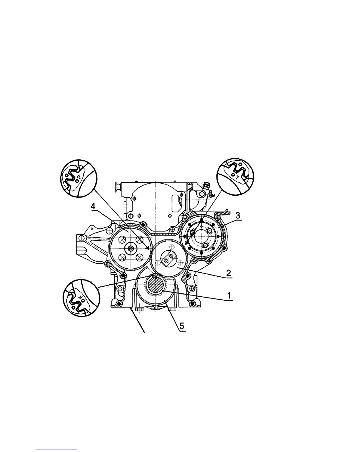
The synchro nization of the crankshaft and camshaft rotation speed signals comi ng to an
electronic fuel supply control unit and matched with the gas distribution mechanism operation is reache d by in st a llat i on of d istribution gears accordi ng to the marks shown on
Fig.2.
1-crankshaft gear; 2 - intermediate gear; 3- fuel injection pump drive gear; 4 – camshaft gear; 5- oil
pump drive gear.
Fig.2- Distribution gears mounting diagram
1.2.2.5 Lubrication system
The diesel en gine lubrication system, as shown on Fig.3, is a combine d one: some parts
are lubricate d unde r pre s sure , ot he r by spray i ng.

The crankshaft an d cam s ha ft be ari ng s, the interm e dia te gea r bush, the ro ck e rs bus h, the
pneumatic compressor crankshaft big end bearings, the turbocharger shaft bearing are
lubricated under the pres sure from the oil pump. The cylinder liners, pistons, piston pins,
bars, pushers, camshaft lobes and fuel injection pump pa rts are lu bric a ted by sp ray in g.
The lubrication system consists of oil pump 3, oil filter with paper filter elements 4, centrifugal oil filter 7, liquid-oil heat exchang er 6.
Oil pump 3 is a gear type, single-section, fixed to the engine cylinder block by bolts. The
oil pump is dr iv en by a gear mounted on the crankshaft.
There is a by-pass valve 5 in t he oil pump set for the pressure of 0,7…0,75 MPa. When
the oil pressure exceeds mentioned these values the oil is by-passed from the discharge
cavity to the suction cavity. The adjustment is done on a test-bench using adjustment
washers.
The oil pump, via oil receiver 2, takes oil from oil sump 1 and via the channels in the cy linder block d elivers oil to a full flow oil filter with a paper filter element, while some portion of the oil goes to a centrifugal oil filter for purification and subseguent sink into the
oil sump.
Installed in the ho usi ng of fi l ter 4 is an un adj us ta b le safety valve18. It has been designed
for keeping the oil pressu re within 0,28...0,45MPa in t he ma in o il du ct. At the oil pressure exceeding 0,45MPa the safety valveopens and the redundant oil (oil reserve) is sunk
into the engine oil sump via the protective valve.
The oil purified in oil filter 4 goes to liquid-oil heat exchanger integrated in the engine
cylinder block. The filter element has a by-pass valve 20. I n the event of overclogging of
the paper filter element or at starting the engine with cool oil, when the filter element resistance goes over 0,13... 0,17 MPa, the by-pass valve opens and the oil bypassing the filter paper is fed in the oil system. The by-pass valve is unadjustable.
From the liquid-oil heat exchanger, v ia the channels in the engi ne cylinder block, the
cooled oil com es into the main oil duct from which, via the channels in the engine cylinder block, it is delivered to all of the main end cranksha ft bearings and the camshaft supports.
From the second, fourth and sixth main end bearings, via inject or s inte gr ate d in the cylinder block m ain end supports, the oil is delivered for pistons cooling.
From the main end bearings, via the channels in the crank shaft, oil com es for lubrication
of the big end bearings.
From the first main end bearing, via special channels in the front cyl inder block wall,
the oil is delivere d to inte rm ed ia te ge ar bu sh 14 a nd fu rther, via a channel in the dis tr ibution pump, it goe s for lu b ric a tio n of the pa r ts of fue l in jec ti o n pum p 17.
The valvemechanism par ts are lubricated by the oil coming from the se cond and the third
camshaft supports via the channels in the cylinder block and cylinder heads, bores in the
third and the fourth rocker racks into the inner cavity of the rocker ax le and, throu gh the
holes, to the rocker bushes from which vi a a chann el it c ome s to the a dj ustm e nt sc re w
and the bar.
The oil is delivered to bearing unit of of turbocharger 15 via a tube coonected at theoutlet of the oil filter with a paper filter el ement.
The oil is delivered to pneumatic comp ressor 16 via an oil duct conne cted at the heat exchanger outle t. The o il is sunk from the compressor i nto the engine oil sump.
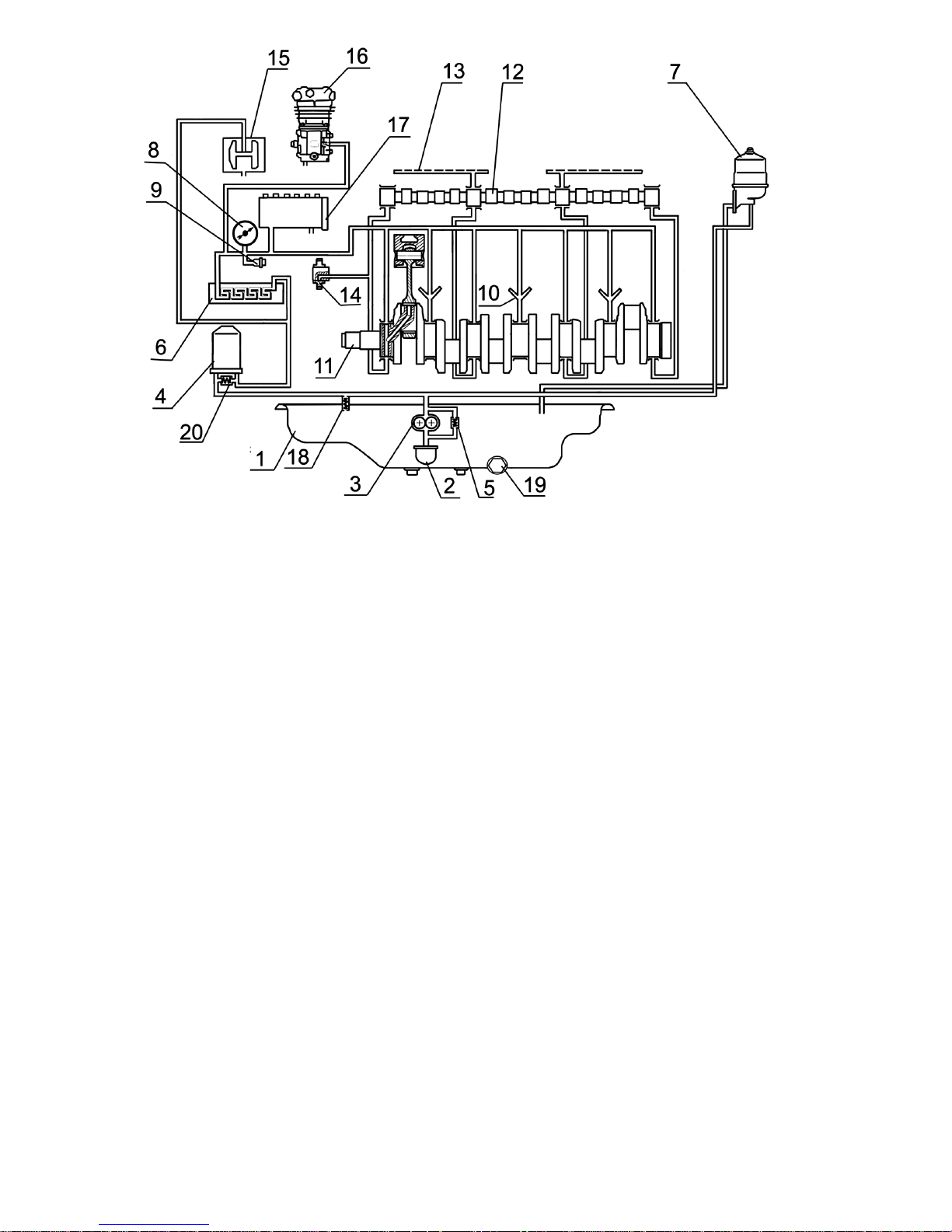
1 - oil sump; 2 – oil receiver; 3 – oil pump; 4 – paper oil filter; 5 – by-pass valve; 6 – liquid-oil heat
exchanger; 7 – centrifugal oil filter; 8 – oil pressure indicator; 9 – oil pressure al arm sensor; 10 – piston
cooling injectors; 11 – crankshaft; 12 – camshaft; 13 – ro cker axle oil channel; 14 – inter mediate gear;
15 – turbocharger; 16 – compressor; 17 – high pressure fuel injection pump; 18 – safety valve19 – oil
drainage plug; 20 – paper filter element by-pass valve.
Fig.3 - Lubric at i on sy stem diagram
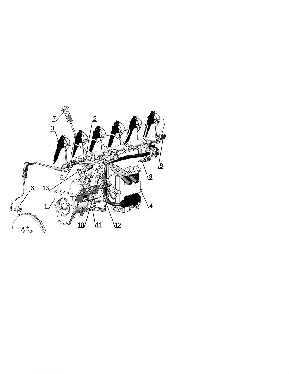
1.2.2.6 Pow er sys te m
The diesel en gine power system (Fig.4) according to engine builds shown in Table 6 consists of: Common RAIL accumulator type fuel supply system including high pressure fuel
injection pump 1, injectors 8, high pressure fuel accumulator, operation environment
condition sensors (fuel and air temperature and pressure, electr omagnetic act uators
(pressure regulator23), injectors electromagnetic valves), el e ctronic unit for control and
communication circuits, control and diagnostics board (in a tractor or an agricultural
machine)*; low pressure pipelines; high pressure pipelines; intake manifold; exhaust
manifold, re circulated gas cooler; turbocharger; fine fuel filter; fuel pre-filter*; air
cleaner*; fuel tank; charge air cooler*; silencer*.
Shown on the engine feed sy stem diagram is a device for d iesel engine startup aid under
conditions of low ambient temperatures – glow plug.
The COMMON RAIL structural diagram (electric and hydraulic) is shown on Fig.5.
* - to be installed by c ust om er.
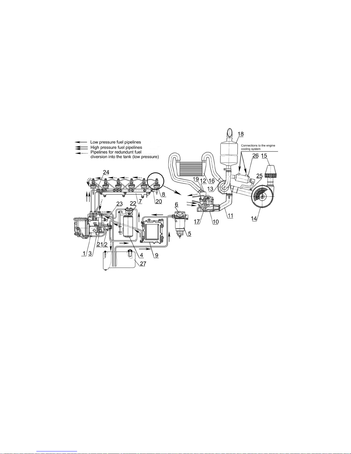
1 – high pressure fuel injection pump; 2 – Fuel feed pump (booster pump); 3 – oil duct; 4 – fine fuel filter; 5 – fuel pre-filter; 6 – hand fuel feed pump (priming
pump); 7 – high pressure fuel accumulator; 8 – injector; 9 – electronic control unit radiator; 10 – cylinder head; 11 – exhaust manifold; 12 – intake manifold; 13 –
turbocharger; 14 – air cleaner; 15 – monocylone; 16 – charge air cooler; 17 – glow plug; 18 – silencer; 19 – char ge air temperat ure and pressu re sensor; 20 – fuel
high pressure sensor; 21 – camshaft angle sensor; 22 – fuel temperature and pressure sensor; 23 – pressure regulator; 24 – pressure limiting valve; 25 – air filter clog
sensor; 26 – recirculated gas cooler: 27 – fuel tank.
* Sensors and actuating mechanisms location is shown on Fig.4а, Table 8.
Fig.4 - Diesel engines D-260.1S3A, D-260.2S3A, Д-260.4S3A power system diagram
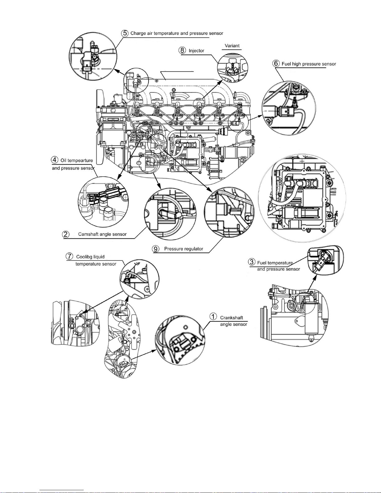
Fig.4а – Locat ion of sen sor s and actuating mechanisms

Table 8
No
Sensor and actuating me chanism Location
1
Crabkshaft ang le se n sor
Distribution cover
2
Camshaft angle sensor
High pressure fuel injection pump
housing
3
Fuel temeper ature and pressure sensor
Finr fuel filter housing
4
Oil tempera ture and pressure sensor
Heat exchanger
5
Charge air temperature and pressure sensor Intake manifold
6
Fuel pressure sensor Fuel high pressure accumulator
7
Cooling liquid temperature sensor
Thermostat housing
8
Injectors
Cylinder head
9
Pressure re gulator
High pressure fuel injection pump
1- high pressure fuel inj ection pump; 2 – high pressure fuel accumulator; 3 – injector; 4 – Electronic Control Unit (ECU); 5 – pressure limiting valve; 6 –
angle sensor; 7 – temperature and pressure sensor in the intake manifold; 8 – fuel high pressure sensor; 9 – cooling liquid temperature sensor; 10 – fuel temperaure and pressure sensor; 11 – angle sensor; 12 – pressure regulator; 13 – oil temperature and pressure sensor.
Fig.5 – CRS system structural diagram (electric and hydraulic)


1.2.2.6.1 High press ure fuel injection pump
Installed in diesel engines are High Pressure Fuel Injection Pumps (Fig. 6).
High pressure fuel inject ion pump (HPFIP)is designed to create fuel reserve, ke eping and
regulating pre s sure in the fu el reg u la tor.
Mounted on HPFIP are fuel priming pump 2 driven by camsha ft 13 and pressure reg ulator 3.
Inside the HPFIP hous ing the re ar e two plu n ger s 3 (Fig.7) actuated by camshaft 2.
The camshaft, through a driver half-coupling is kinematic connection with the engine
crankshaft through distribution gears.
The fuel having passed the coarse fuel f ilter with a moisture separator is further fed by
the fuel priming pump to the HPFIP connector via the fine fuel filter under the pressure
of 0,8...0,9 Mpa.
Under the influence of the created pumping pressure the fuel, via cha nne l 5, comes into a
plunger chamber.
The incoming camshaft moves the plunger up whilethe inley hole of the inlet channel is
overlapped by valve 4 and with the further plunger rise the fue l is com p re sse d in th e
plunger chamber.
When the pressure reaches the level equal to that kept in the high pressure accu-
mulator, va lve 6 opens. The compressed fuel comes into the high pressure circuit.
The plunger deliv e rs the f uel ti ll it re ac hes it s TDC (To p Dea d Cent er) , th en the pre ss ure
goes down, the exhaust valve closes.
Since HPFIP has been designed for supply of large fuel amount, at the engine idle and
at partial lo ads an excess of compressed fuel takes pl ace which, via ball valve 8 of pressure regulator 11 an d via the bac k ru nof f duc t is re tur ned i nt o th e fuel ta nk.
The pressure regulator sets the pre s sure in the high-pressure accumulator, depending on
the engine load, speed and the engine thermal state.
With extremely high pressure in the accu mul at or t he reg ul a tor valv e ope ns an d a port io n
of the fuel is diverte d from the ac cum ul a tor via the back runoff duct to the fuel tank.
The pressure regulator is mounted to the HPFIP housing with a flange. Armature 10
presses the ball of valve 8 to the valve keeper with the valve spring in order to disconnect
the the high and the low pre ss u re circuits.
The switched on electroma gnet 9 moves armature 10 applying additio nal force for
pressing the ball to the keeper.
The armature is all flushed by fuel which lubricates the friction surfaces and remov es excessive heat. The w ork ing pa rt s of the fu el pump are lubricated by oil coming from the
diesel engine lubricatio n system. The from the fuel pump housing is drained into t he engine oil sump. When a new pump is installed in an engine, it must be preli-minarily fille d
with oil for 200 cm
3
Oil is added through a special orifice, item 7 (Fig. 6).
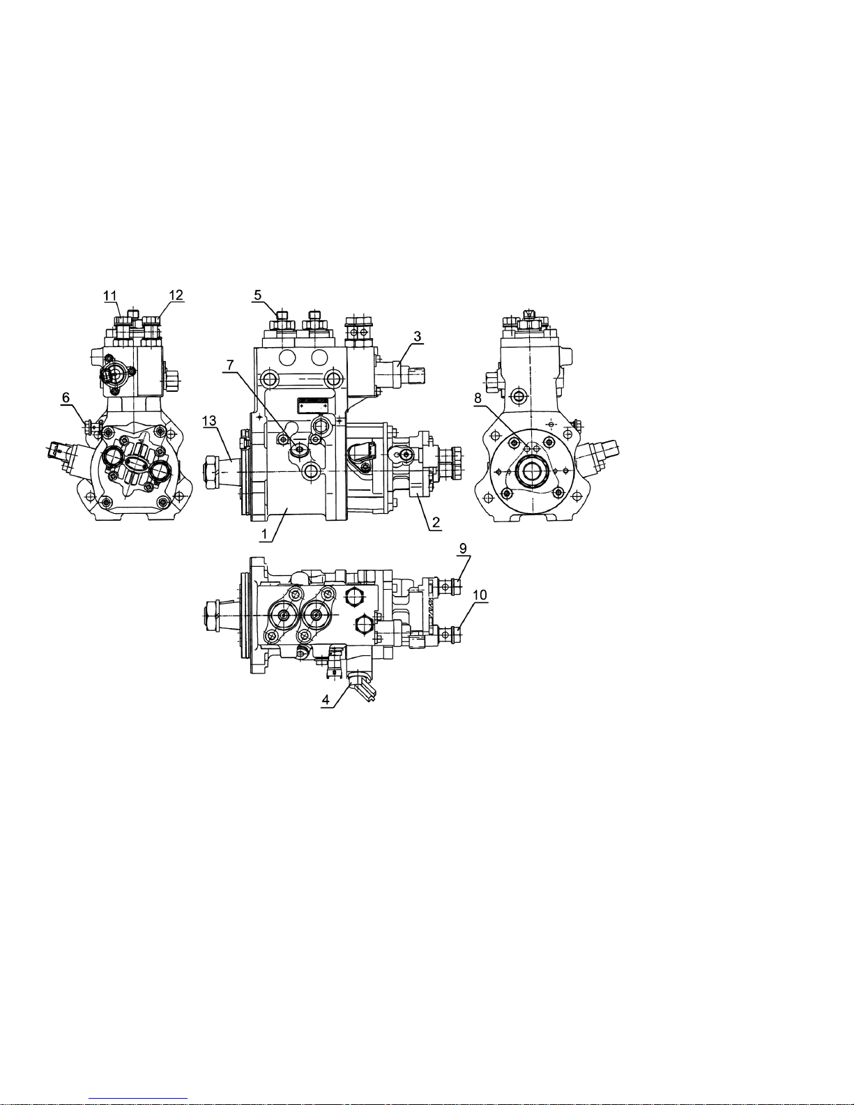
1 – High pressure fuel injection pump; 2 – fuel priming pump (feed pump); 3 – pressure regulator; 4 – angle sensor; 5 – fuel diversion from the fuel a ccumulator connector; 6 – oil inlet connector; 7 – oil orifice plug; 8 – oil diversion holes; 9 – fuel inlet connector from the fuel pre-filter; 10 – fuel otlet connect or
to the fine fuel filter; 11 – fuel inlet conector from the fine fuel filter; 12– redundant fuel diversion into the fuel tank connector; 13 – camshaft.
Fig. 6 - High pressure fuel injection pump CPN2.2
1- high pressure fuel injection pump housing; 2 – camshaft; 3 – plunger; 4 – intake valve; 5 – inlet channel; 6 - exhaust valve; 7 – outket channel; 8 – v alve ball; 9 – elect ri c ma gn et ; 10 – armature; 11- pressure regulator; 12 - electric magnet terminals; 13 – fuel priming pump; 14 – fuel priming pump drive
gear with a pulse rim.
Fig.7 – High pressure fuel pump schematic diagram.
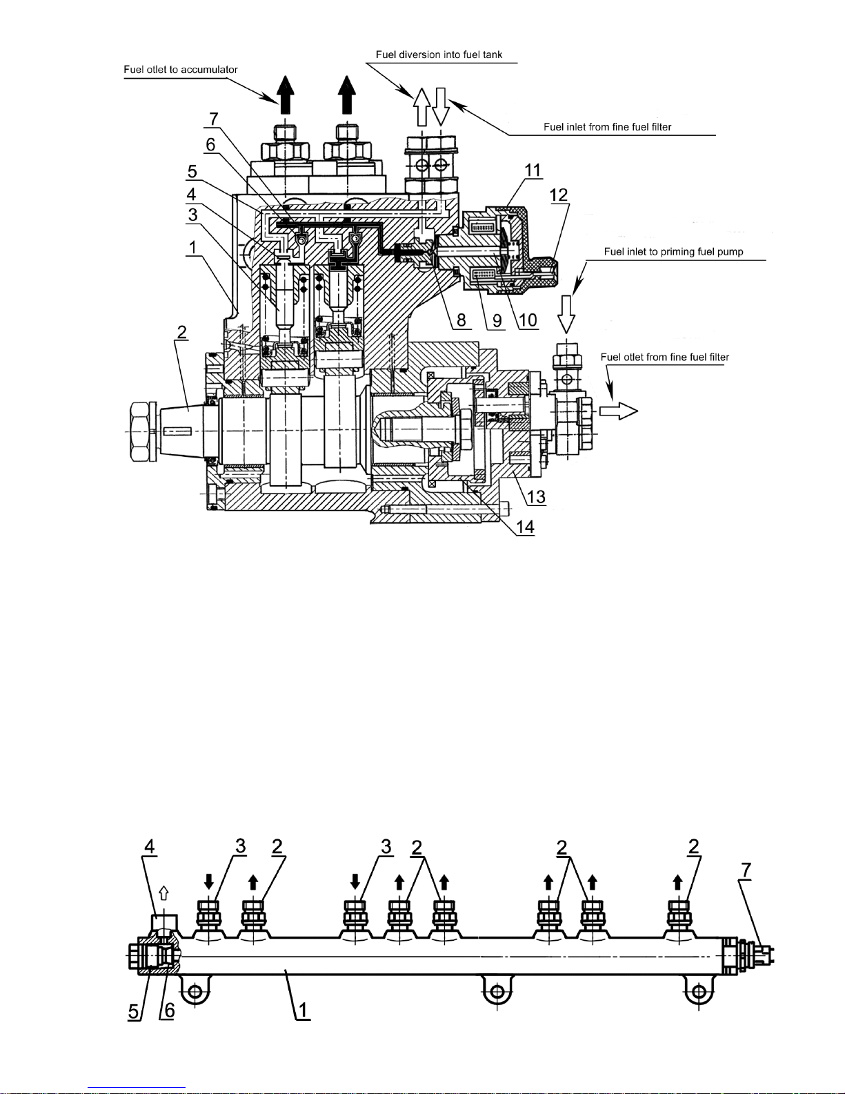
1.2.2.6.2 High press ure fuel accumulator
High pressure fuel accumu lator (Rail) is a volume storage of fuel under high pressure.
Simultaneously, the accumulator smoothes pressure fluctuations that occur due to the
pulsating flow of fuel from HPFIP, and also because of the injectors during injection due
to nonsynchronous fuel pressure pulses coming from t he HPFIP and c onsumed through
the injectors as well as due to the multiple fuel mass excess in t he ac cumulator working
as a damper for small dose pressure pulse s, the incoming and consumed ones.
1 – high pressure fuel accumulator; 2 – otl et connectors; 3 – inlet connector; 4 – back runoff connector;
5 – pressure limiting valve; 6 – valve core locking cone; 7 – fuel high pressure sensor.
Fig. 8 – High pressure fuel accumul ator
Accumulator 1 has the sha pe of pipe at the ends of which are installed fuel pressure sensor 7 and pressure lim iti n g valv e 5. Al ong the pi pe pe rim e ter t h ere are hig h pre ss ur e
pipelines connectors 2, 3 and back runoff connector 4.
The fuel from HPFIP is dir ected via the h igh pressure duct to inlet con nectors 3 of the
accumulator. The fuel accumulator is coupled with the injectors by high pressure fuel
pipings linked with the accumulator outlet connectors
The accumulator is permanently filled with fuel u nder high pressure. The pressure value
is kept on a constant level and may be regulated by valve 5 (Fig. 8), de pe nd ing on t he engine operation pa r am ete rs.
The pressure limiting val ve keeps a definite pressure value in the accumulator working as
a reducing (protective) valve. The valve housing on the accumulator side has a ch annel
closed by valve core cone 6. A spring. A spring firmly presses the cone to the valve seat
under normal operating pressure, so that the accumulator remains closed. In the event of
the pressure in the accumulator exceeding the operating value, the cone moves aw ay
from the valve seat and th e fuel be in g und e r high pr es su re is di ve rte d to the back r u no ff
duct. As a result the fuel p res sure in t he acc umu l at or goe s down.
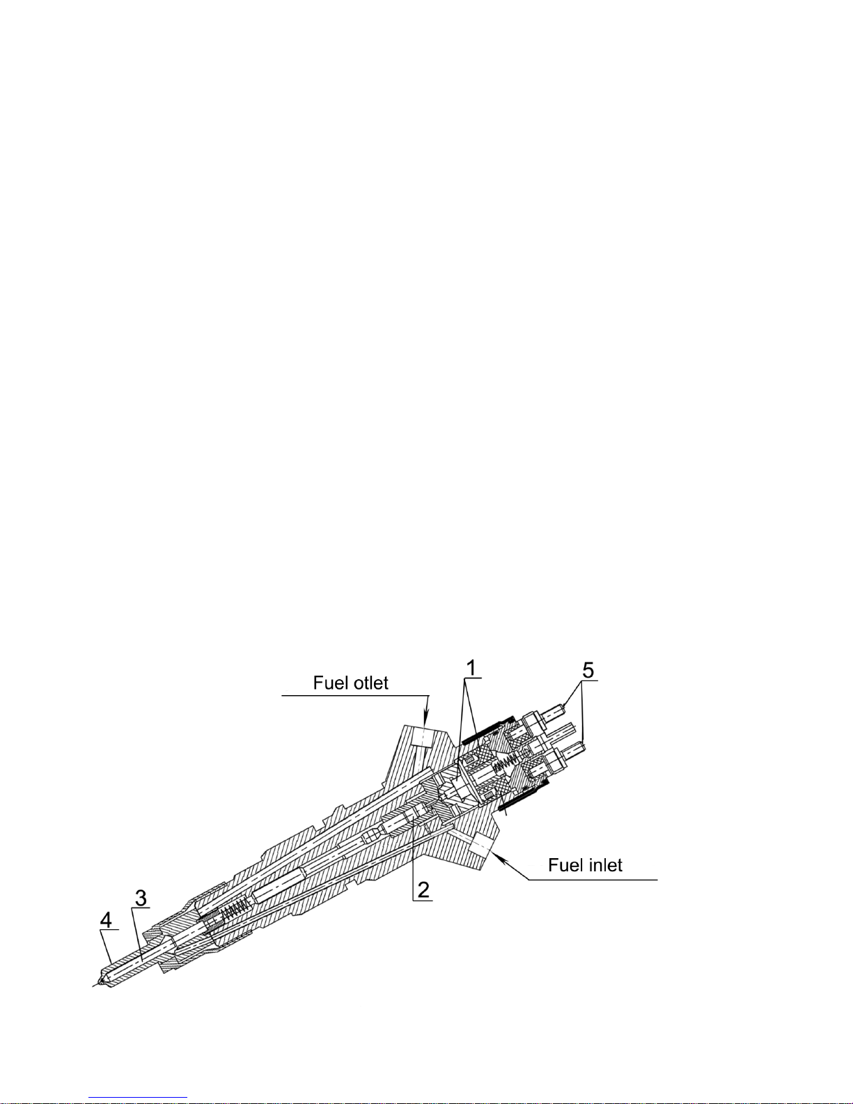
1.2.2.6.3 Injector
Injector (Fig.9) is designed for deliveryi ng fue l i n the di es el e ng ine cyli n der a nd en su rin g
the necessary sp ray in g.
Installed in the engines are CRIN2 injectors manufactured by”BOSCH” (Germany).
The required moment of the start of injecti on an d the f uel su p ply amoun t are prov i de by
the operation of the inject or electromagnetic valve. The moment of the start of in je ction
in the “angle-tim ing” coordinates is set by the diesel engi ne electronic c ontrol system.
1 – electromagnetic valve; 2 – controlling valve; 3 – atomizer needl e; 4 – atomizer housing; 5 – electric
terminals.
 Loading...