

MINSK D-243, D-245 Maintance Manual

“MINSK MOTOR PLANT”
Open Joint Stock Company
D-243, D-245 Diesel Engines
and Their Modifications
OPERATION AND MAINTENANCE MANUAL
243-0000100RE
Minsk, 2010

2
Contents
1. DESCRIPTION AND OPERATION ...................................................................................... 4
1.1. Description and Operation of the Diesel Engine ............................................................... 4
1.1.1. Purpose of the Diesel Engine ......................................................................................... 4
1.1.2. Technical Data .............................................................................................................. 5
1.1.3. Engine Components ...................................................................................................... 8
1.2. Description and Operation of the Diesel Engine Components ......................................... 12
1.2.1. General Information .................................................................................................... 12
1.2.2. Description ................................................................................................................. 12
2. INTENDED USE.................................................................................................................. 24
2.1. Pre-operation of the Diesel Engine ................................................................................. 24
2.2. Using the Engine............................................................................................................. 24
2.2.1. Actions of the Operating Personnel When Executing the Tasks of Use ........................ 24
2.2.2. Troubleshooting .......................................................................................................... 27
2.2.3. Safety Requirements ................................................................................................... 30
3. MAINTENANCE ................................................................................................................. 31
3.1. General Directions ........................................................................................................... 31
3.2. Routine Maintenance Schedule....................................................................................... 31
3.3. Diesel Engine Maintenance Procedure ............................................................................ 32
4. ROUTINE REPAIRS ............................................................................................................ 57
4.1. Main Guidelines for Disassembling and Reassembling the Diesel Engine .......................... 57
4.2 Current repair of diesel engine components………………………..……………………..59
4.2.1. General instructions for disassembling of water pump………………………………...60
5. STORAGE ............................................................................................................................ 61
6. TRANSPORTATION ........................................................................................................... 62
7. DISPOSAL ........................................................................................................................... 62
Appendix А. Chart of Use of Combustive-Lubricating Materials ...……………………….……63
Appendix B. Schedule of Spare Parts and Accessories (SPA) ……………………………..……66
Appendix C. Adjustment Parameters of the Diesel Engine …………..…………….……………67
Appendix D. Adjustment Parameters of the Fuel Pumps ……..…………………………………68
Appendix E. Identification of diesel engine and turbocharger malfunctions……………….……70
Appendix F. Scheme of diesel strapping.......................................................................................
71

The present Operation and Maintenance Manual is intended for operators, drivers and
mechanics of the machines and units equipped with the D-243 and D-245 diesel engines and their
modifications.
This manual provides brief technical description, proper maintenance and service rules
for the D-243, D-245 diesel engines and their modifications.
The reliable long-term operation of diesel engines depends on the timely and high-quality
performance of all guidelines of this Operation and Maintenance Manual.
Due to permanent improvement of the diesel engines, some alterations not reflected
herein may be made to the design of individual assembly units and parts.
If consumer is not follow to the rules and conditions of operation, technical servicing, transportation and storing conditions, specified in the present operation manual, violate integrity of manufacturer label, change diesel engine design and also use expendable
materials (combustive-lubricating materials, spare parts and accessories) for technical servicing and current repairing, which not agreed with the designers documentation of OJSC
«MMW», the guaranty for the diesel engine is not valid.
If diesel engine owner or other person executes diesel engine and it components repairing and restoring works, during validity period of the guaranty for the diesel engine
without attraction of manufacturer specialist or specialist of authorized dealer center, the
guaranty for the diesel engine is not valid.

1. DESCRIPTION AND OPERATION
1.1. Description and Operation of the Diesel Engine
1.1.1. Purpose of the Diesel Engine
The scope of application of the diesel engines are places with unrestricted air exchange.
The diesels are designed for the operation at the ambient temperature from minus 45C
up to plus 40С.
The diesel engines D-243, D-245 and their modifications are designed for mounting on
the tractors of the class of 1.4-2.0 tons of traction, agricultural, forest and industrial machines and
units of various purposes.

1.1.2. Technical Data
1.1.2.1. The main parameters and characteristics of the diesels are given in Table 1.
Table 1
Description of Units of Values
parameters measure-
ment
D-241 D-242 D-243 D-243.1 D-244 D-245 D-245.2 D-245.4 D-245.5
1. Type Four-stroke diesel engine without supercharging Four-stroke
diesel engine with
supercharging
Four-stroke
diesel engine with
supercharging and interim cooling of supercharging
air
Four-stroke diesel engine with supercharging
2. Fuel injection system Direct fuel injection
3. Number of cylinders 4
4. Firing order 1 – 3 – 4 – 2
5. Cylinder bore in (mm) 4.33 (110)
6. Stroke in (mm) 4.92 (125)
7. Displacement gal liq US
(l)
1.25 (4.75)
8. Allowable longitudinal and lateral tilt of the working diesel, not
more than
degrees 20
9. Power according to GOST
18509-88:
- rated kW 52.9 45.6 59.6 61.0 41.9 77 88 60 65
- operational kW 50.5 44.1 57.4 58.1 40.4 74 85 57 62
10. Rated and operational power
tolerances
kW +3.7 +3.7 +3.7 +3.7 +3.7 +4.0 +4.0 +4.0 +4.0
11. Rated rotational speed rpm 2,100 1,800 2,200 2,200 1,700 2,200 2,200 1,800 1,800
12. Maximum idling rotational
speed restricted by the governor,
not more than
rpm 2,275 1,950 2,380 2,380 1,850 2,380 2,380 1,980 1,980

Table 1
Description of Units of Values
parameters measure-
ment
D-241 D-242 D-243 D-243.1 D-244 D-245 D-245.2 D-245.4 D-245.5
13. Minimum stable idling rotational speed, not more than
rpm 600 600 600 600 600 700 700 700 700
14. Compression rate (design) 16 16 16 16 16 15.1 15.1 15.1 15.1
15. Direction of the engine crankshaft rotation according to GOST
22836-77
Right-hand (clockwise)
16. Maximum value of torque, not
less than
lb.ft (N.m) 204.3
(277.0)
205.0
(278.0)
219.8
(298)
219.8
(298)
224.9
(305.0)
284.3
(385.5)
365.0
(495.0)
269.9
(366.0)
292.6
(396.8)
17. Rotational speed at the maximum torque, not less than
rpm 1,600 1,400 1,600 1,600 1,400 1,400 1,400 1,400 1,400
18. *Specific fuel consumption in
the rated power mode
lb/kW.h
(g/kW.h)
0.498
226.0
0.498
226.0
0.498
226.0
0.498
226.0
0.498
226.0
0.485
220
0.485
220
0.478
217
0.478
217
19. * Specific fuel consumption in
the operational power mode
lb/kW.h
(g/kW.h)
0.518
235
0.518
235
0.518
235
0.518
235
0.518
235
0.504
229
0.504
229
0.498
226.0
0.498
226.0
20. Total oil consumption with the
account of replacement for the
whole warranty period of operation, not more than
Percentage
of the fuel
consump
tion
1.1 1.1 1.1 1.1 1.1 1.3 1.3 1.3 1.3
21. Oil pressure in the main lubrication gallery at the temperature of
70-95C:
psig (MPa)
- at the rated rotational speed 36.26-50.76 (0.25 – 0.35)
- at the minimum idling rota-
tional speed, not less than
11.6 (0.08)
22. Weight of the dry diesel engine
with fan, alternator, air cleaner
without clutch
lb (kg) 947/1079
(430/490)
947/1079
(430/490)
947/1079
(430/490)
947/1079
(430/490)
947
(430)
991/1068
(450/485)
1035
(470)
991
(450)
991
(450)
23. Turbo-supercharger none none none none none ТКР 6 or
С1470В/8.12М or К 27
ТКР 6-01 or
С1470В/6.12М
24. Starting device:

Table 1
Description of Units of Values
parameters measure-
ment
D-241 D-242 D-243 D-243.1 D-244 D-245 D-245.2 D-245.4 D-245.5
electric starter 24.3708 or
CT-
142M or
AZJ 3124
24.3708 or
CT-
142M or
AZJ 3124
24.3708
or
CT-142M
or AZJ
3124
24.3708 or
CT-
142M or
AZJ 3124
24.3708 or
CT-1
42M or
AZJ 3124
24.3708 or
CT-142M
or AZJ
3124or
20.3708 or
СT-142Н
20.3708 or
СT-142Н
20.3708
or СT-
142Н
20.3708 or
СT-142Н
Notes:
1. The values of power and fuel consumption of the engines are given for the standard atmospheric conditions and fuel density:
- atmosphere pressure: 101.3 kPa (14.7 psi, 760 mm of mercury);
- air temperature: 20С;
- relative humidity of air: 50%;
- fuel density: 0.83 t/m3 (6.92 lb/gal liq US).
When measuring the parameters of the diesel engine in the conditions different from the standard ones the values of the power and specific fuel consumption
shall be corrected in accordance with GOST 18509-88.
2* The specific fuel consumption shall be considered confirmed, if the deviation does not exceed 5%.

8
1.1.3. Engine Components
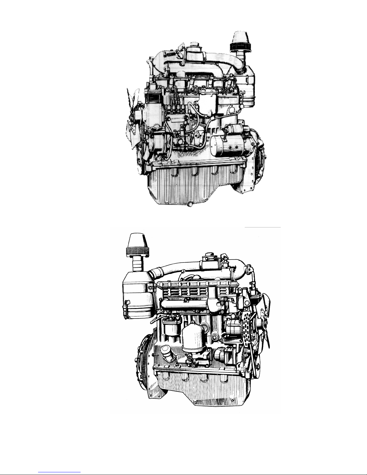
The D-243 diesel engines in accordance with Figs 1 and 2 and the D-245 diesel engines
in accordance with Figs 5 and 6 are basic models. Their modifications differ from the basic model
in the power regulation, standard equipment, starting device and design of some parts.
Depending on the purpose, the diesel engines may be equipped with additional assembly
units: air compressor, gear pump of the steering booster with drive and clutch disk assemblies.
When installing on the tractor (machine), the diesel engine shall be fit additionally with
water and oil radiator, electric equipment as well as control instruments.
The diesel engines can be started by an electric starter.
The design differences of the diesel engines from the basic model consist in the following:
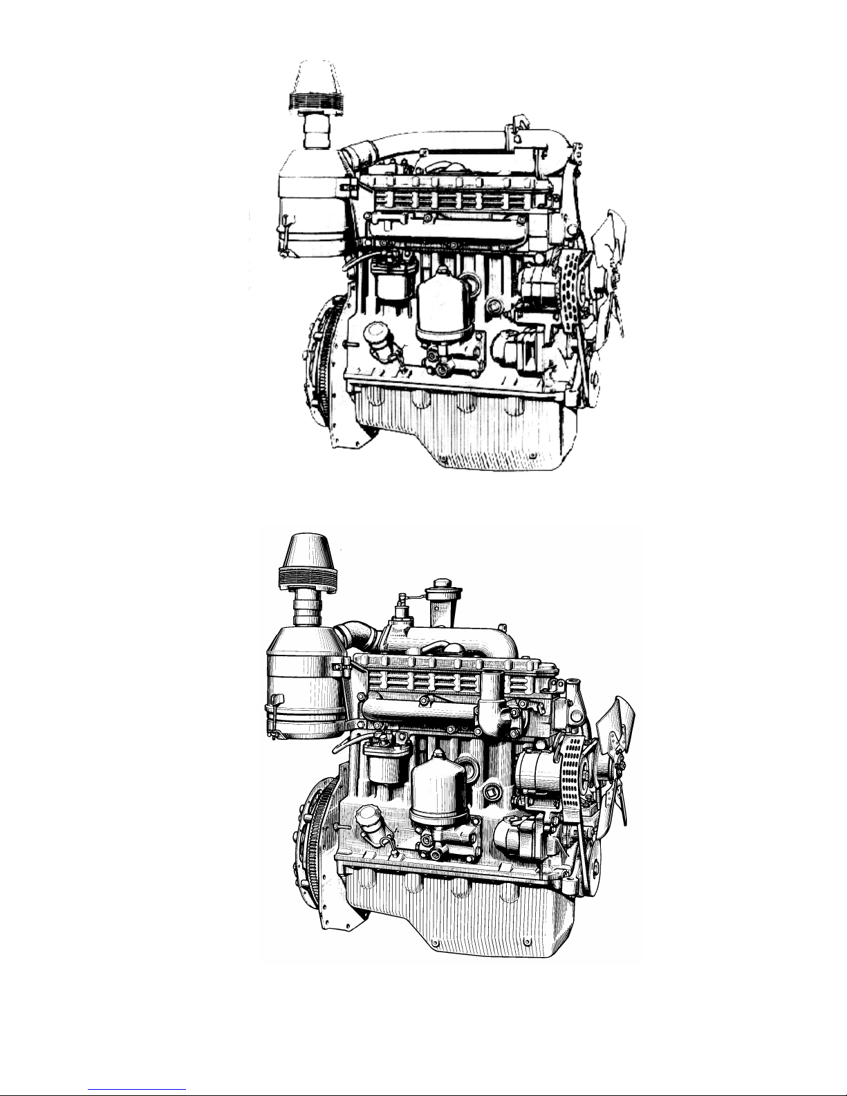
- in the D-241 diesels, in accordance with Fig. 4, the exhaust connection is altered with
installation of a muffler in the zone of the fourth cylinder;
- the D-242 diesel engines, in accordance with Fig. 5, as well as on the D-244, are fitted
with the crankshaft without counterweights, fan with the diameter of 450 mm (17.72 in), shortened intake manifold, crankcase pulley with the diameter of 170 mm (6.69 in), side nipple of the
air cleaner with the diameter of 57 mm (2.24 in), oil pump and its driving gear unified with the D50 diesel.
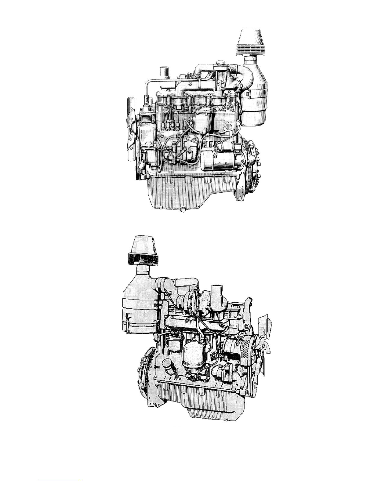
The main differences of the D-245 diesel engine from the D-243 one:
- the turbo-supercharger is installed;
- the design of the connections of the intake and exhaust manifolds, crankshaft pulleys,
water pump and alternator;
- an additional V-belt is introduced for driving the fan and alternator;
- the special sprayers for cooling the pistons with oil jets are provided in the main supports of the cylinder block;
- the fuel pump is equipped with an antismoke corrector (ASC);
- the cylinder head has insert valve seats made of heat- and wear-proof alloy;
- an insert of special cast iron is founded under the first compression ring;
- the upper compression ring has trapezoid shape;
- the crankshaft and connecting rods are made of stronger materials;
- six-blade fan with he diameter of 456 mm (17.95 in);
- high-capacity oil pump;
- air cleaner with the diameter of 270 mm (10.63 in);
- centrifugal oil filter has increased capacity;
- linger flywheel pins for installation of a double-disk clutch.
The main differences of the D-245.2 diesel engine from the D-245 one:
- a supercharging air cooler is fitted;
- adjustment parameters of the fuel pump;
- three-grooved pistons К.343N manufactured by the "Petar Drapshin", Serbia;
- three-ring set (6-2143-25/3, 6-0970-05/4 and 7-2146-54-0/3) of piston rings manu-
factured by the "Buzuluk" Company, Czech Republic;
- Cylinder sleeves 245-1002021-А manufactured by the “Krotoszin” Company, Po-
land.
The diesel engines are equipped with the tachometer drives corresponding to the rated
rotational frequency of the crankshaft.
The tachometer drive housing is marked with numbers. The number 40 indicated that the
reduction gear is intended for the engine with the rated rotational speed of 1,700 rpm, 50 – 1,800
rpm, 80 – 2,100 rpm and 90 – 2200 rpm.
9
Fig. 1 – D-243 Diesel Engine (Left View).
Fig. 2 – D-243 Diesel Engine (Right View)
10
Fig. 3 – D-241 Diesel Engine (Right View).
Fig. 4 – D-242 Diesel Engine (Right View).
11
Fig. 5 – D-245 Diesel Engine (Left View).
Fig. 6 – D-245 Diesel Engine (Right View)
12
1.2. Description and Operation of the Diesel Engine Components
1.2.1. General Information
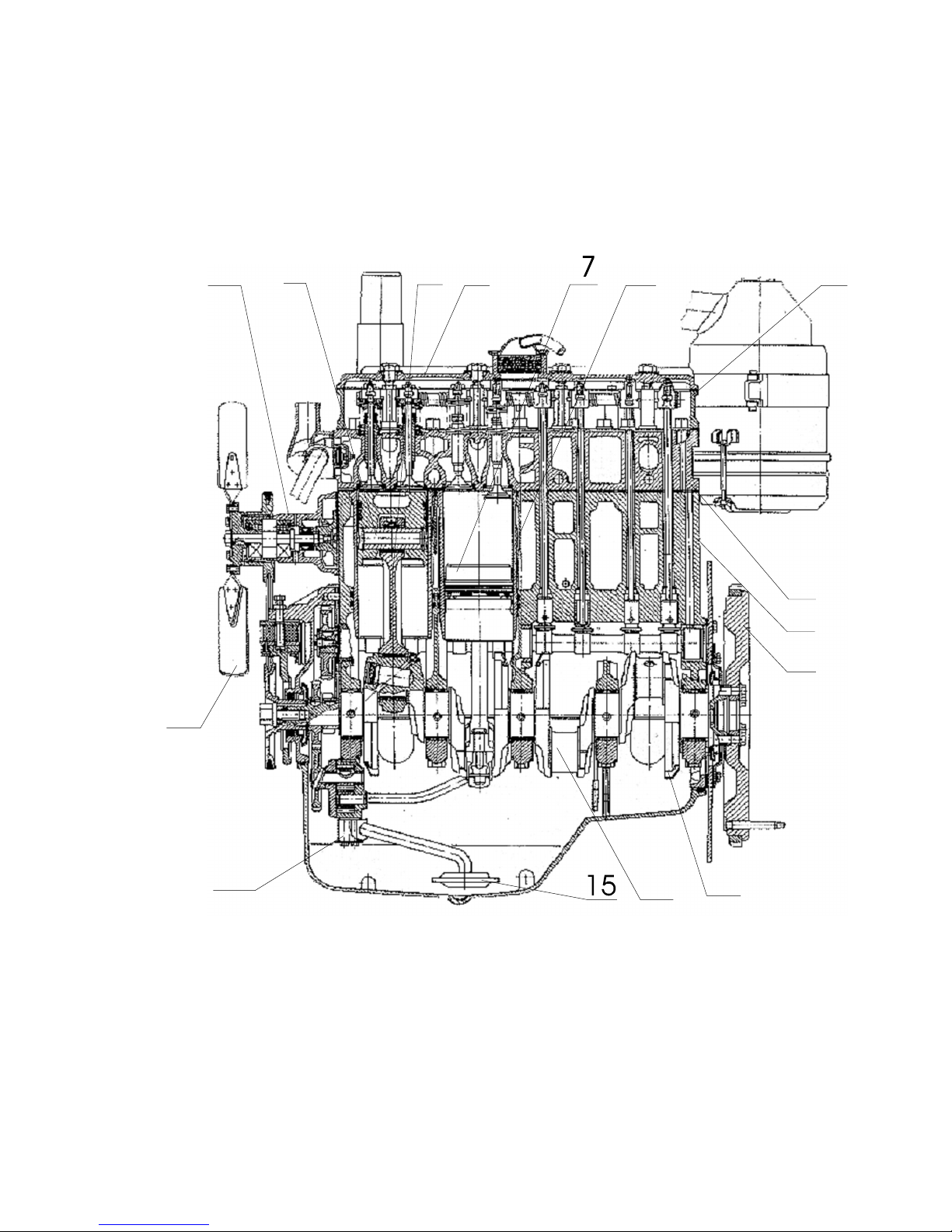
As seen in Fig. 7, the diesel engine consists of the cylinder block, cylinder head, crank
mechanism, valve gear link as well as assemblies and units of the feed, lubrication, cooling and
starting systems as well as electric equipment.
1
2
14
13
12
11
10
3
4
5 6
8
9
1 – oil pump; 2 – fan; 3 – water pump; 4 – piston pin; 5 – connecting rod; 6 – cap; 7 – piston; 8 – cylinder
sleeve; 9 – cylinder head cover; 10 – cylinder head; 11 – cylinder block; 12 – flywheel; 13 – counterweight;
14 – crankshaft; 15 – oil collector.
Fig. 7 – D-243 Diesel Engine (Longitudinal Section).
1.2.2. Description

13
1.2.2.1. Cylinder Block
The cylinder block is the main engine case and is designed as a special rigid cast-iron alloy mono-block. Four removable sleeves made of special cast-iron, are fixed in block bores.
Sleeves are installed into the cylinder block in two centring lands, the upper and lower
ones. In the upper land the sleeve is fixed by means of a shoulder while in the lower land it is
sealed by means of two rubber rings located in cylinder block grooves.
According to their internal diameter, the sleeves are divided into three size groups, the
large (Б=L), medium (С=M) and small (М=S) ones. The group is marked on the inserting cone of
the sleeve. The sleeve sizes are given in Section 4.1. The diesel engine shall be fitted with sleeved
of the same size group.
The coolant circulates in the space between cylinder block and the sleeves.
The end walls and cross hatches of the cylinder block have special lugs in the lower portion to form upper supports of the crankshaft. The lugs are covered with caps serving as lower
supports of the crankshaft. The lugs together with the caps form beds for main bearing shells. The
beds are machined in assembly with the caps; therefore the caps are not interchangeable.
The cylinder block has a main oil channel supplying oil via a number of transverse channels to main bearings of the crankcase, and then to the camshaft journals.
The cylinder block of the D-245 diesel engine has sprayers in the second and forth supports of the crankshaft. These sprayers serve for cooling the pistons with oil jets.
On the external surfaces of the cylinder block there are machined mating faces for
mounting the centrifugal oil filter, water pump, coarse and fine fuel filters as well as oil filler neck.
1.2.2.2. Cylinder Head
The cylinder head is a cast-iron casting, in the inner passages of which there are intake
and exhaust channels to be closed by means of the valves. To ensure the heat abstraction, the cylinder heat has inner passages for coolant circulation.
The cylinder head of the D-245 diesel engine has inserted valve seats made of heat- and
wear-proof alloy. On the top of the cylinder head there are rocker shaft assembly, rocker shaft
brackets, head cover, intake manifold and cover cap, covering the camshaft valve gear link. Four
fuel injectors are mounted in the cylinder head from the side of the fuel pump, and the exhaust
manifold – from the side of the alternator. To seal the joint between cylinder head and cylinder
block, a gasket of asbestos-steel web is inserted. The cylinder sleeve borings and oil passage are
back-lined by sheet steel. When assembling the engine at the factory, the cylinder holes of the
gasket are back-lined additionally with fluoroplastic split rings.
1.2.2.3. Crank Mechanism
The main parts of the crank mechanism are the crankshaft, connecting rods, pistons, piston rings, piston pins, main bearings and connecting rod bearings as well as flywheel.
The crankshaft is made of steel. It has five main bearing journals and four rod journals.
Inside of the crank-pin journals, oil chambers are provided for centrifugal cleaning of lubrication
oil. The oil chambers of the journals are plugged with threaded plugs.
Axial force of the crankshaft is taken by four split rings made of aluminium alloy that are
fixed in the bores of the cylinder block and cover of the fifth main bearing. The counterweights
are provided for reducing the loads imposed on the bearings from the inertia forces at the first,
fourth, fifth and eight crank webs. At the front and at the back the crankshaft is sealed by means
of collars. The timing gear (crankshaft gear), oil pump driving gear, water pump and alternatordriving pulley are installed on the front end of the crankshaft. The flywheel is fastened to the rear
flange of the shaft.

14
The crankshaft may be manufactured and installed in the engine of two production sizes
(nominal values). The crankshaft with the connecting rod and main bearing journals manufactured
according to the second nominal size has additional marking on the first web. The size of the main
and connecting rod webs as well as respective marking of the crankshaft is given in Section 4.1.
The piston is made of aluminium alloy. The combustion chamber is made in the piston
head. The piston has four grooves in its upper part; the first three grooves are intended for filling
the compression rings and the fourth for the oil ring. The piston of the D-245 engine is fitted with
an insert of special cast iron under the upper trapezoid-shaped compression ring. The holes for
piston pins are bored in the piston pin boss.
According to the external diameter of the skirt, the pistons are sorted according to three
size groups (Б=L, С=M and М=S). The group is marked on the piston head. The piston sizes are
given in Section 4.1. When being mounted in the engine, the sleeves and pistons must be of the
same size group.
The piston rings are made of cast iron. The upper compression ring is chromium-plated,
having rectangular cross section and no marking. It is mounted in the groove in arbitrary manner.
The second and third compression rings are conic and have marking “up” on the end surface at
the lock. The oil ring is box-shaped and fitted with spiral steel extender.
The upper compression ring of the D-245 engine is made of high-strength cast iron and
has the shape of isosceles trapezium while the other rings are unified with those of the D-243 engine.
The diagram of mounting of the piston rings is given in Fig. 33.
The piston pin is hollow, made of chromium-nickel steel. The axial shift of the pin in the
bosses is restricted by stop rings.
The connecting rod is made of steel and has double-T section. A bush is pressed in its
upper head. There are holes for lubricating the piston pin in the upper head and bush of the connecting rod.
The insert bed in the lower head of the connecting rod is bored as an assembly with the
cover; therefore the connecting rods are not interchangeable. The connecting rod and its cover
have the same numbers stamped on their surfaces. Moreover, the connecting rods have the weight
groups according to the weights of the upper and lower heads. The designation of the group according to the weight is stamped on the end face of the connecting rod upper head. The engine
shall be fitted with the connecting rods of the same group.
The inserts of the main and connecting rod bearings of the crankshaft are made of
steel and aluminium. The inserts of the main and connecting rod bearings of two sizes in accordance with nominal sizes of the crankshaft are used in the diesel engines. The four repairing sizes of
the inserts are provided also for repairing the diesel engine.
The flywheel is made of cast iron and bolted to the crankshaft flange. The gear ring is
pressed onto the flywheel.
1.2.2.4 Valve Gear Link
The valve gear link includes gears, camshaft, intake and exhaust valves as well as their
fasteners and actuators, such as followers (pushers), push rods, rocker arms, rocker shafts, adjusting screws with nuts, plates, valve keepers, valve springs, brackets and rocker axle.
The camshaft is supported by three journals and is connected with a crankshaft via timing gears. The three bushes pressed in the cylinder block bores serve as camshaft bearings. The
first bush (from the fan side) made of aluminium alloy has a thrust shoulder keeping the camshaft
from the axial travel; the other bushes are made of cast iron.
The cam followers (pushers) are made of steel and have spherical bottoms. Since the
camshaft cams are made with small inclination, the push rods are in rotary motions during the
work.

15
The push rods are made of steel bars. The spherical part that goes inside the cam follower and the rod cup are hardened.
The rocker arms are made of steel. They swing on the rocker shaft supported by four
brackets. The outermost brackets have increased hardness. The rocker arm axle is hollow and has
eight radial holes to supply lubrication oil to the rocker arms. The rocker arms travel along the axle is limited by the spacer springs.
The intake and exhaust valves are made of high-temperature steel. They travel in guide
bushes pressed in cylinder heads. Each valve is closed by means of two springs: the outer and inner ones. The springs actuate the valve via plates and valve keepers.
The Seal collars fixed on guide bushes do not let oil penetrate into engine cylinders
through clearances between the valve stems and the guide bushes.
1.2.2.5. Fuel System
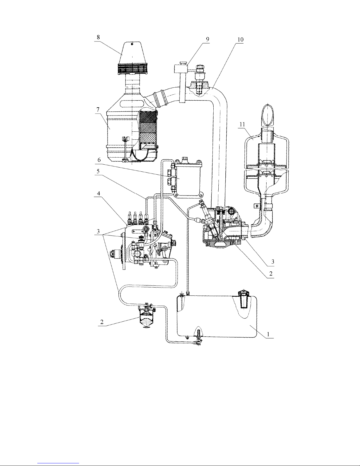
As shown in Fig. 8, the engine fuel system consists of the fuel pump, injectors, low and
high pressure pipes, air cleaner, intake and exhaust manifolds, coarse and fine fuel filters as well as
the fuel tank mounted onto the tractor (machine).
The fuel system of the D-245 diesel engine includes a turbo-supercharger.
16
1 – fuel tank; 2 – coarse fuel filter; 3 – fuel pipes; 4 – fuel pump; 5 – high-pressure fuel pipe; 6 –
fine fuel filter; 7 – air cleaner; 8 – coarse air filter; 9 – electric torch heater; 10 – intake manifold; 11 –
muffler; 12 – exhaust manifold; 13 – fuel injector.
Fig. 8 –D-243 diesel engine feeding system diagram.

17
1.2.2.5.2. Fuel Pump
The D-243 diesel engine and its modifications are equipped with the high-pressure fuel
pump 4UTNI and the D-245 engine and its modifications – with the pumps 4UTNI-T or
4UTNM-T.
All the pump models are driven from the engine crankshaft via timing gears. The fuel
pumps are equipped with all-mode governors and piston-type priming pumps.
The pump governor contains the fuel feed corrector, automatic fuel feed intensifier (for
starting the engine) and, in the 4UTNI-T and 4UTNM-T pumps there is also the pneumatic
smoke restrictor (pneumatic corrector).
The fuel-priming pump is mounted on the housing of the high-pressure pump and driven
by the eccentric of the camshaft.
The working parts of the fuel pumps are lubricated with flowing oil coming from the engine lubricating system into the pump housing through the special hole in the flange. The oil is
drained from the pump into the engine pan through the special channel in the flange.
When mounting a new or repaired pump onto the engine, it is necessary to fill it with
200...250 cm3 (0.42-0.53 pt liq US) of engine lubrication oil through the oil filler hole in the regulator cover.
1.2.2.5.3. Fuel Injector
The fuel injector is intended for spraying the fuel into the engine cylinder. It ensures the
necessary atomisation of fuel and restricts the beginning and end of the feed. The diesels are
equipped with fuels injector fitted with closed-type five-hole atomizers 17.1112010-01 (manufactured by the “KA” Joint-Stock Company) or 171.1112010-01 (manufactured by the “AZPI”
Closed Joint-Stock Company).
The fuel injector 17.1112010-01 (the “KA” Joint-Stock Company) has the marking
"171", 171.1112010-01 (manufactured by the “AZPI” Closed Joint-Stock Company) – “171-01”
while the fuel injector atomizer has the marking “17”. The marking is stamped on the fuel injector
housing and on the atomizer body.
1.2.2.5.4. Course Fuel Filter
The course fuel filter serves for the preliminary purification of fuel by removing mechanical contaminants and water.
The course fuel filter consists of the housing, slinger with the screen element, diffuser
and cup with a damper.
The fuel sediment shall be drained out from the hole in the sleeve bottom to be closed
with a plug.
1.2.2.5.5. Fine Fuel Filter
The fine fuel filter is intended for final purification of fuel.
The fine fuel filter has a replaceable paper element.
When passing through the blinds of the paper filter element, the fuel becomes free of mechanical contaminations. In the lower portion of the filter housing there is a hole for draining the
sediment with a plug.
There is a vent plug on the filter cover for bleeding air from the fuel system.

18
1.2.2.5.6. Air Cleaner and Inlet Line
The air cleaner is intended for purification of air to be sucked into the cylinders.
The air-cleaner of the diesel engine is combined: the dry centrifugal purification and oil
dust-trap with wet kapron filter. In the air-cleaner housing there are three filter elements of
kapron bristle having different diameters.
The D-245 diesel and its modifications can be fitted also with an air-cleaner consisting of
the main and control paper filter cartridges.
To ensure the better filling of the cylinders with air, the D-241, D-243 engines are
equipped with the intake manifold with selected length and diameter of intake pipe and port of the
intake manifold.
In the intake manifold port there is a shutter for emergency stop of the engine. The shutter is controlled from the cabin of the tractor (machine).
The D-242 and D-244 diesels are equipped with a simplified intake manifold without the
emergency stop shutter.
All the diesel engines equipped with electric starter have the electric torch pre-heater,
which is intended for preheating the air to be sucked into the cylinders with the purpose of easing
the engine start at low ambient temperatures.
1.2.2.5.7. Turbo-Supercharger
The D-245 diesel engine and its modifications are equipped with the turbo-supercharger
using the energy of exhaust gas for supercharging the air into the engine cylinders.
The principle of operation of the turbo-supercharger consists in directing the pressurized
exhaust gas from the engine cylinders into the turbine scroll channels through the exhaust manifold. When expanding, the gas rotates the rotor connected with the compressor impeller, which
sucks the air through the air-cleaner and delivers it into the engine cylinders under pressure.
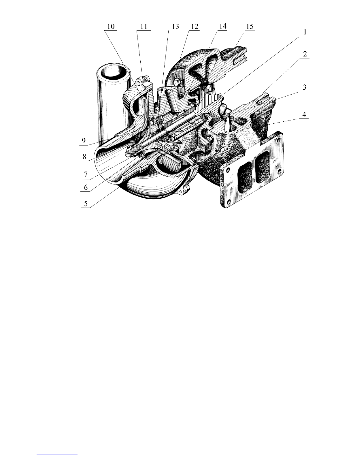
As shown in Fig. 9, the turbo-supercharger is designed according to the following
scheme: radial centripetal turbine and single-stage compressor with the console arrangement of
wheels relatively to the supports.
The rotational speed of the compressor, feed and pressure of the air discharged depend
on the diesel engine operating mode.
The turbo-supercharger turbine housing 2 is founded of high-strength cast iron. The
flow-through part of the turbine for passing the exhaust gas is formed by the housing and the turbine wheel.
The compressor housing 11 is founded of aluminium alloy, its flow-through part is
formed by the housing and the compressor wheel.
The housings of the turbine and the compressor are fastened to the housing of the bearings 14, which is founded of high-strength cast iron.
The turbine wheel 1 is founded of heat-proof alloy and welded to the rotor wheel.
The compressor impeller 6 is founded of aluminium alloy and fastened to the shaft by
means of a special nut.
The rotor shaft rotates in the radial bearing made in the form of floating non-rotating
mono-bush 3. The mono-bush is fixed in the housing of bearings by means of a pawl. The axial
travel of the rotor is perceived by the thrust bearing 12.
The turbo-supercharger bearings are lubricated and cooled with oil coming from the centrifugal oil filter through the pipeline. Both radial and thrust bearings provide additionally for the
centrifugal oil cleaning. The oil is drained to the engine crankcase through an oil-draining pipe.
Between the compressor and the turbine there are gas and oil seals in the form of spring
rings 8 and 15 mounted in the rotor grooves. To improve the efficiency, an oil-guard is mounted
from the compressor side and a screen from the turbine side.
19
1 – turbine wheel with shaft; 2 – turbine housing; 3 – mono-bush; 4 – oil-guard; 5 – eccentric ring;
6 – compressor wheel; 7 – special nut; 8, 15 – O-rings; 9 – diffuser; 10 – cover; 11 – compressor
housing; 12 – thrust bearing; 13 – distance bush; 14 – middle housing (housing of bearings).
Fig. 9 – Turbo-supercharger.
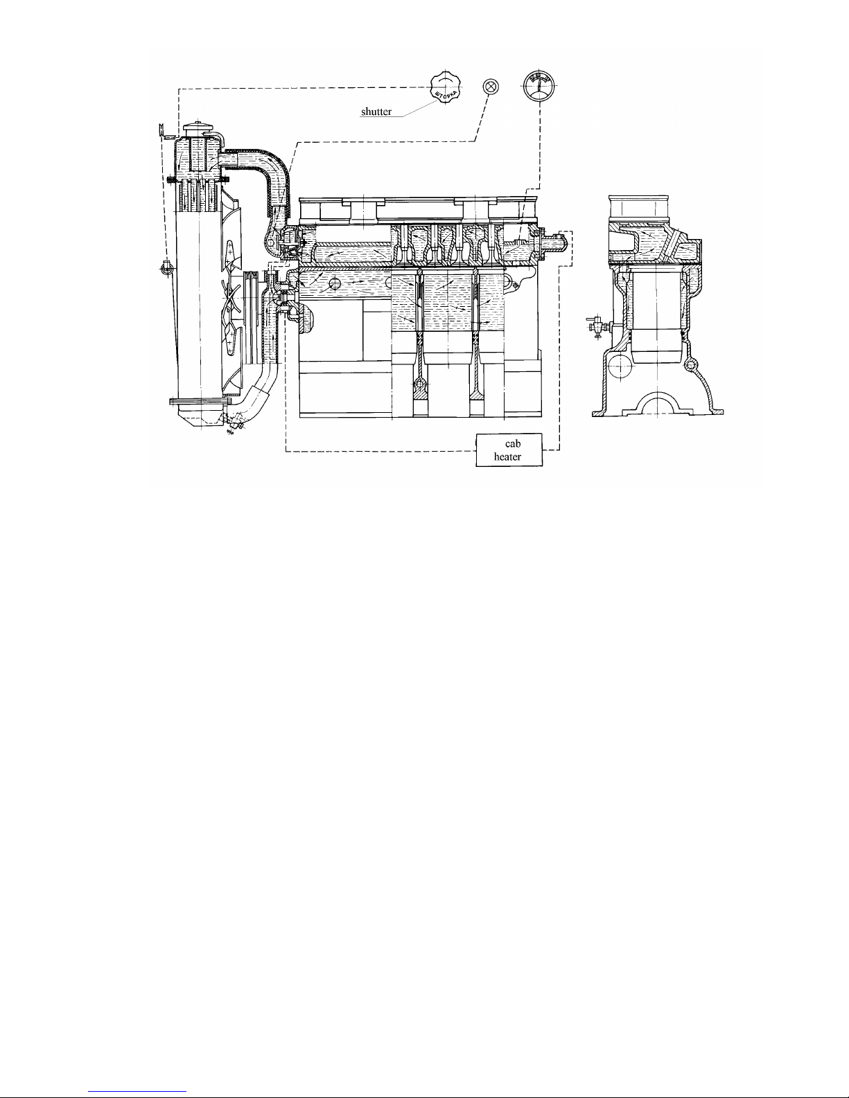
1.2.2.6. Cooling System
As seen from Fig. 10, the diesel is cooled by means of the liquid-type cooling system
with forced circulation of the coolant from the centrifugal pump. The temperature of the coolant
in the system is controlled by means of a distance temperature gauge, the sensor of which is
mounted in the cylinder head. In the D-245 diesel engine and its modifications, the place for
mounting the sensor in the thermostat housing is also provided for. The operation of the diesel
engine is prohibited, if the coolant overheating indicator lights up. The temperature of the
coolant in the cooling system must be maintained within 75-95C.
20
Fig. 10 – Diagram of the Cooling System
The thermostat with solid filler serves to speed up the engine warming-up after starting it
and automatic regulation of the temperature regime at various loads and ambient temperatures.
The water pump, fan and alternator are driven from the engine crankshaft pulley by
means of a V-belt. On the D-245 engine these units are driven by means of two belts.
The "Litol-24" lubricant is injected into the bearing cavity of the pump during the assembling. The pump bearings need not lubrication for the whole period of operation of the diesel engine.
The cooling system of the engines equipped with starting engines is connected with the
cooling system of the starting engine. The cooling jacket of the starting engine cylinder communicates with the cooling jacket of the diesel engine cylinder head and the cooling jacket of the cylinder head of the starting engine communicates with the housing of the diesel engine thermostat.
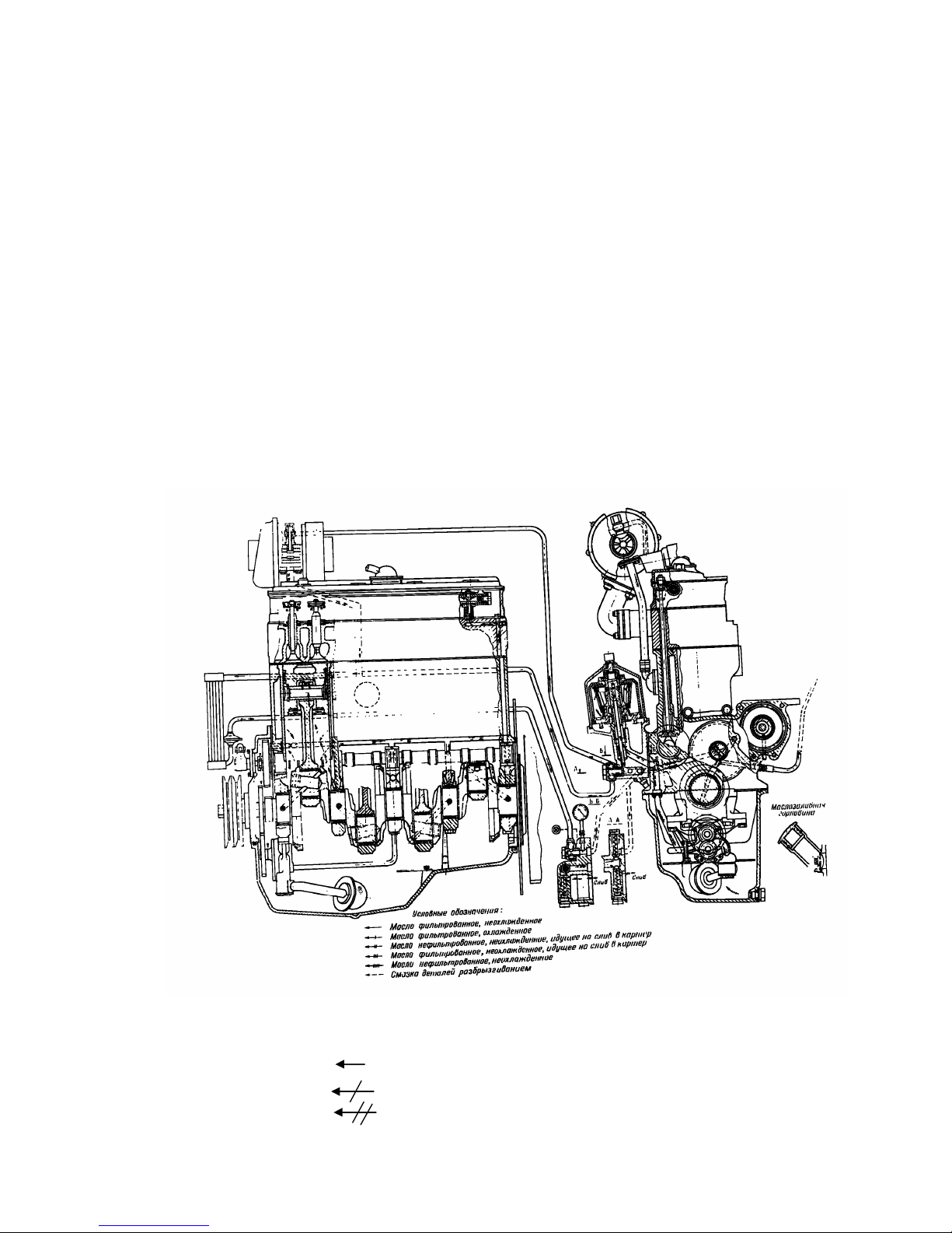
1.2.2.7. Lubricating System
The diesel engine has a combined lubricating system. The bearings of the crankshaft and
camshaft, bushes of the intermediate gear and fuel-pump driving gear, the connecting-rod bearing
of the air-compressor crankshaft, as well as valve driving gear and on the D-245 engine also the
turbo-supercharger shaft bearing, in accordance with Fig. 11, are lubricated under pressure. The
sleeves, pistons, piston pins, push rods, pushers and cams of the camshaft are splash lubricated.
The oil pump 12 is a gear-type, single-section one bolted to the first main bearing cover.
The pump delivers oil via pump outlet pipe and cylinder block channels to the centrifugal filter 3,
where it is cleaned from foreign particles, combustion and wear products. Cleaned oil is transferred from the centrifugal oil filter to the radiator for cooling, and, on the D-245 engine, additionally to the turbo-supercharger shaft via oil duct. The oil is transferred from the oil radiator into the diesel main pipelines.
21
In the centrifugal oil filter housing there are reducing 7, drain valve 8 and safety valve
10.
Upon starting the diesel engine the non-heated oil comes directly to the diesel engine
pipeline through the reducing (radiator) valve bypassing the radiator due to high resistance of the
radiator.
The safety valve (centrifugal filter valve) serves for maintaining the oil pressure before
the filter rotor of 101.8 psig (7 kgf/cm2). When the pressure exceeds the above value, some noncleaned oil is drained through the valve into the engine crankcase.
Both reducing and safety valves are not adjustable.
It is strictly prohibited to turn out the plugs of the reducing and safety valve.
The drain valve is adjusted to the pressure if 29...43.5 psig (2.0...3.0 kgf/cm2) and used
for maintaining the necessary oil pressure in the main pipeline of the diesel engine. The surplus oil
is drained into the engine crankcase through the valve.
From the main gallery of the engine the oil is passed to all the main bearings of the
crankshaft and necks of the camshaft. From the main bearings it is passed to all the connecting
rod bearings. From the first main bearing oil is passed through the special channels to the bushes
of the intermediate gear and the fuel pump driving gear as well as to the fuel pump.
The parts of the valve gear link are lubricated with oil supplied from the rear bearing of
the camshaft through the channels in the cylinder block, hole in the fourth rocker arm into the inner cavity of the rocker shaft and through the hole to the rocker arm bush and then to adjusting
screw and push rod.
1 – oil radiator; 2 – piston cooling fuel injectors; 3 – centrifugal oil filter; 4 – protective strainer; 5 –
oil-filler neck; 6 – plug of the oil sump; 7 – reducing valve; 8 – drain valve; 9 – pressure gauge; 10 – safety
valve; 11 – oil receiver; 12 – oil pump.
Symbols: filtered oil, hot
filtered oil, cold
non-filtered hot oil to be drained to the oil sump

22
filtered hot oil to be drained into the oil sump
non-filtered hot oil
splash-lubrication of parts
Fig. 11 – D-245 diesel engine lubricating system.
The air-compressor is supplied with oil from the main oil gallery via engine block chan-
nels and special pipe. From the air-compressor oil is drained into the engine crankcase.
1.2.2.8. Electric Equipment and Starting System
The electric equipment of the D-243 diesel engine and its modifications may include the
G964.3701-1 or G964.3701-1-2 alternators with the rated capacity of 1 kW and rated voltage of
14 V, or G994.3701-1 alternators with the rated power of 1 kW and rated voltage of 28 V, and
that of the D-245 diesel engine and its modifications may include the G968.3701-1 or G968.37011-2 alternators with the rated capacity of 1 kW and rated voltage of 14 V or G998.3701-1 alternators and rated capacity of 1 kW and rated voltage 28 V.
The alternator is a brushless AC generator with built-in compact voltage regulator and
single-sided electromagnetic excitation.
The alternator operates in parallel with the storage battery and serves for recharge of the
latter as well as for supplying the electric power consumers mounted on the machine (tractor)
with DC current.
For starting the diesel engine, an electric starter.
The starting device of the diesel engines equipped with electric starters includes also the
electric touch pre-heater.
The diesel engines are equipped with the 24.3708 starters with the power of 4 kW (5.3
hp) at the voltage of 12 V or the ST 142M or ARJ3124 ones. On the customer’s request, the diesels may be equipped with the 20.3708 starter with the power of 5.9 kW (8.0 hp) at the voltage of
24 V or the ST142N one.
The starter is a DC series-excitation electric motor. The starter is switched on remotely
by means of electromagnetic starter relay and starter switch.
The electric torch pre-heater serves for pre-heating of the air to be sucked into the cylinders for the purpose of facilitating the engine start.
To facilitate the engine start at low ambient temperatures all the diesels are provided
with the places for mounting the PZhB-200G pre-starting pre-heater.
1.2.2.9. Air Compressor
The air compressor is intended for supplying the pneumatic braking system of trailers
with compressed air and inflating the tyres.
The air compressor is a piston-type one-cylinder air-cooled one.
The air compressor is driven from the fuel pump driving gear. The air is sucked into the
cylinder of the air compressor from the intake pipe of the diesel engine through a plate valve.
The air compressor parts are lubricated with the oil coming from the lubricating system
of the diesel engine. From the air compressor the oil is drained into the diesel crankcase.
 Loading...