

Page 1

BN 7x50 C II
Bedienungsanleitung
Instructions
Page 2

2 3
MINOX BN 7x50 C II
• Deutsch Seite 3
• English page 16
Inhaltsverzeichnis
Einleitung 4
Lernen Sie Ihr Fernglas kennen 4
Bedienelemente 5
Allgemeingültige Bedienhinweise 5
Vorbereiten des Fernglases 5
- Anbringen des Trageriemens 5
- Anbringen des Okularschutzdeckels 6
- Objektivschutzdeckel 6
- Einstellen des Fernglases 6
- Einstellen des Augenabstandes 6
- Fokussieren (Scharfeinstellung) 6
- Benutzung mit und ohne Brille 7
- Anbringen an einem Stativadapter 8
Einlegen und Auswechseln der Batterien 8
Entfernungsmessung mit dem Kompass 9
- Bedienung des MIL Fadenkreuzes
für die Fernmessung (Telemetrie) 9
- Messen des Elevationswinkels 10
- Messen des Azimuten (Horizontalwinkel) 11
- Bedienung des Kompasses 11
Allgemeine Pflegetipps 13
- Fernglas-Tasche im Lieferumfang enthalten 13
- Reinigen des Fernglases 13
- Reinigung der Objektiv- und Okularlinsen 13
- Serien-Nummer 13
Tipps zur Benutzu ng des Fern glases 14
Technische Daten 14
Gewährleistungsbedingungen 15
Erweiterter MINOX Garantieservice 15
2
14
13
8
3
64
5 1
12 11
7 108/9
Page 3

4 5
Allgemeingültige Bedienhinweise
Vorbereiten des Fernglases
Im Lieferumfang des MINOX BN 7x50 C II ist ein Neopren-Trageriemen enthalten. Wir empfehlen Ihnen den
ständigen Gebrauch des Trageriemens beim Einsatz
Ihres MINOX Fernglases.
Hinweis: Durch die Anbringung und Nutzung des
Trageriemens lassen sich mögliche Fallschäden am
Fernglas verhindern.
Anbringen des Trageriemens
Fädeln Sie den Trageriemen durch die TrageriemenHalterung ( 3) am Gehäuse des Fernglases. Ziehen Sie
das Ende des Trageriemens zur Schnalle zurück und
führen Sie dieses anschließend von hinten durch die
Schnalle, um den Trageriemen zu fixieren. Verfahren
Sie mit der Trageriemen-Befestigung entsprechend
auf der gegenüberliegenden Seite des FernglasGehäuses. Nachdem Sie den Trageriemen an beiden
Seiten des Fernglases befestigt haben, stellen Sie
anschließend den Trageriemen auf die gewünschte
Länge ein.
Bedienelemente
(siehe Darstellung auf Seite 2)
1. Stülpaugenmuschel
2. Okularring
3. Trageriemen-Halterung
4. Kompass-Gehäuse
5. Lichtdurchlass
6. Kompass-Lichtschalter
7. Abdeckschraube Stativgewinde
8. Batteriefach
9. Batteriefachdeckel
10. Objektiv
11. Okularschutzdeckel
12. Öse zur Okularschutzdeckel-Befestigung
13. Objektivschutzdeckel
14. Objektivschutzdeckelhalterung
Lernen Sie Ihr Fernglas kennen
• Porroprismen-Fernglas
• Okulare mit Einzeleinstellung
• Schwimmfähig, wasserdicht bis 5 m (0,5 bar)
• Beschlagfrei dank Stickstofffüllung
• Robustes, leichtes Makrolon-Gehäuse
• Griffige Gummiarmierung
• Analoger beleuchtbarer Kompass mit Strichplatte
• Dioptrienausgleich von – 4 bis + 6 Dioptrien
Warnhinweis: Vermeiden Sie, wie b ei jedem Fernglas, den direkten Blick in helle Lichtquellen mit
Ihrem MINOX Fernglas, um Augenverletzungen
auszuschließen.
Einleitung
Herzlichen Glückwunsch!
Mit einem Fern glas aus dem Hause MINOX haben Sie
sich für ein Produkt von höchster optischer und feinmechanischer Qualität entschieden. Diese Anleitung
soll Ihnen ein Be rater sein, um das Leistung sspektrum
Ihres MINOX Fernglases optimal zu nutzen.
Wir wünsche n Ihnen mit Ihrem neuen MINOX Pro dukt
viel Freude!
Page 4

6 7
verfahren Sie bitte wie folgt: Wählen Sie ein entfernt
liegendes Beobachtungsobjekt auf einer Distanz von
etwa 50 Metern.
Schließen Sie zunächst das rechte Auge. Schauen Sie
mit dem linken Auge durch das Okular Ihres Fernglases. Drehe n Sie den linken Okularring nach re chts (im
Uhrzeigersinn) bzw. links (gegen den Uhrzeigersinn)
bis Sie das beobachtete Objek t in maximaler Schärfe
sehen. Schließen Sie nun das linke Auge und wiederholen Sie den Vorgang zur Einstellung des rechten
Okulars bis Sie auch hier ein schar fes Bild sehen. Ihr
Fernglas ist nu n auf Ihre individuelle Sehleistung eingestellt.
Beide Okulare verfügen über eine Dioptrienskala.
Merken Sie sich Ihre individuelle Dioptrien-Einstellung
für das linke und rechte Okular oder markieren Sie
dieselbe mit einem Permanent-Stift. Auf diese Weise
lässt sich das Fer nglas jederzeit schnell w ieder auf Ihre individuelle Sehleistung scharf einstellen, nachdem
z.B. eine andere Person das Fernglas genutzt hat und
die Einstellungen ggf. verändert wurden.
Benut zung mit und ohne B rille
Ihr MINOX
BN 7x50 C II
verfügt über sogenannte
Stülpaugenmuscheln, also stülpbare Augenmuscheln
aus elastischem Gummi, über die Sie den Augenabstand anpassen können, je nachdem ob Sie mit oder
ohne Brille durch Ihr MINOX Fernglas beobachten.
Nutzer, die bei der Beobachtung durch das Fernglas
keine Brille tragen, belassen die Stülpaugenmuscheln
im ausgestülpten Zustand (Werksauslieferungszustand) . In dieser Position ist der richtige Abstand
zwischen Augenpupille und Okularlinse gegeben.
Diese Einstellung ermöglicht zudem eine ruhige
Auflage Ihres Fernglases am Auge und gewährleistet eine Min imierung des Streulichts . Bei Beobachtungen durc h Ihr MINOX
BN 7x50 C II
mit aufgesetzter
Brille müssen die Stülpaugenmuscheln umgestülpt
werden, damit Sie das volle Sehfeld ohne Bildbeschneidung am Rand überblicken können.
Warnhinweis: Vermeiden Sie de n direkten Blick mit
Ihrem MINOX Fe rnglas in helle Lichtquellen , um Augenverletzungen auszuschließen.
Einstellen des Fernglases
Ihr MINOX BN 7x50 C II sollte vor Gebrauch auf Ihre
individuellen Bedürfnisse eingestellt werden. Beachten
Sie hierzu bitte die nachstehenden Hinweise.
Einstellen des Augenabstandes
Ihr MINOX
BN 7x50 C II
verfügt über eine Knickbrücke, über die Sie den A bstand der beiden Oku lare auf
Ihren individuellen Augenabstand einstellen können.
Ihr MINOX
BN 7x50 C II
ist richtig auf Ihren Augenabstand ange passt, wenn Sie beim Beoba chten durch Ihr
MINOX Fernglas ein großes, kreisrundes Bild sehen.
Verstellen Sie Ih r MINOX Fernglas so, bis sich die b eiden einzelnen Sehfelder zu einem großen, kreisrunden
Bild überlagern.
Fokussieren (Scharfeinstellung)
Ihr MINOX
BN 7x50 C II
ist mit einer Okular-EinzelFokussierung ausgestattet . Dies hat den Vorteil, dass
alle beobachteten Objekte innerhalb eines Bereiches
von 12 Meter bis Unendlic h scharf abgebildet wer den,
ohne dass die Schärfe Ihres Fernglases auf Nah oder
Fern angepasst werden muss. Der Einstellbereich der
Okulare liegt zwischen – 4 und + 6 Dioptrien.
Um vorab eine optimale Einstellung auf die individuelle Sehleistung Ihrer Augen zu gewährleisten,
Anbringen des Okularschutzdeckels
Verbinden Sie den Okularschutzdeckel (11) über dessen Öse (12) an der linken Seite mit dem Tragerie men. Der Okularschutzdeckel schützt die Optik an den
Okularen vor Fremdkörpern, Regen, Staub und Sand.
Bei Beobachtung durch Ihr Fernglas entfernen Sie den
Okularschutzdeckel vom Okular. Dieser hängt während des Beo bachtens an der linken Seite de s Tragerie mens nach unten, ohne die Sicht zu beeinträchtigen.
Objektivschutzdeckel
Zum Schutz der Objektivlinsen Ihres BN 7x50 C II vor
Fremdkörpern, Regen, Salzwasser, Staub und Sand
dient der Objektivschutzdeckel (13). Diesen können Sie
an Ihrem Fernglas anbringen, indem Sie die Schlaufe
an der Objektivschutzdeckelhalterung (14) über die
Abdeckschraube des Stativgewindes (7) legen und
einfädeln, bis die Schlaufe hinter dem Stativgewinde
vollständig eingelegt ist. Beim Beobachten durch Ihr
Fernglas entfernen Sie den Objektivschutzdeckel vom
Objektiv und lassen diesen einfach lose herab hängen.
Möchten Sie den Objektivschutzdeckel vollständig von
Ihrem BN 7x50 C II abnehmen, ziehen Sie die Schlaufe
der Objektivschutz deckelhalterung vorsichtig hinter
dem Stativgewinde hervor und ziehen dieselbe über
die Abdeckschraube des Stativgewindes (7).
Page 5

8 9
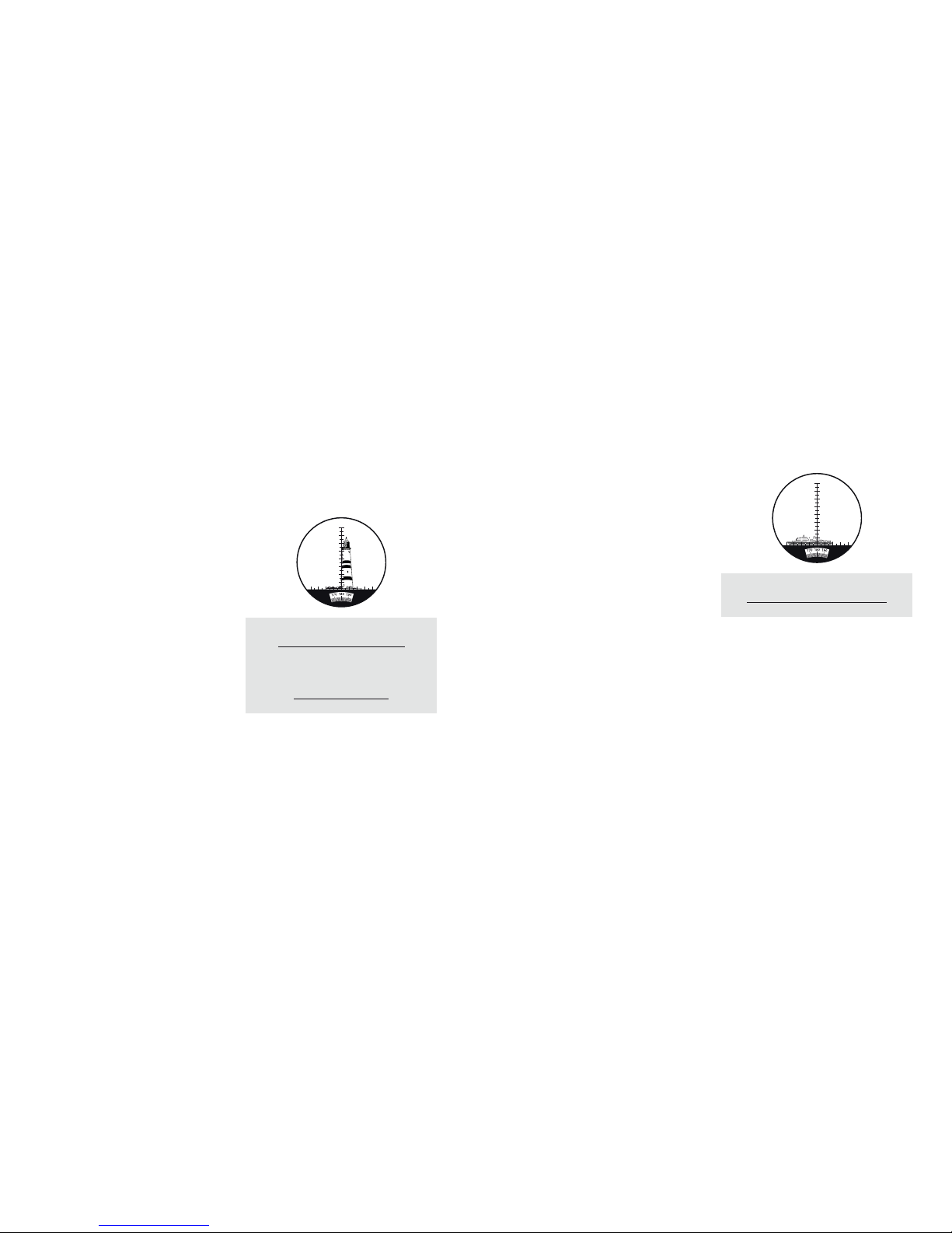
Entfernungsmessung
mit dem Kompass
Bedien ung des M IL Faden kreuzes für die
Fernmessung (Telemetrie)
Mit dem MINOX
BN 7x50 C II
können Sie anhand der
analogen Strichplatte (Fadenkreuz) die Entfernung
beobachteter Objekte bestimmen. Die Entfernung
können Sie mit Hilfe einer einfachen bewährten Formel ermitt eln, wenn Höhe oder Läng e des zu vermessenden Objekts hinreichend bekannt sind. Dies ist in
der Regel der Fall, da es sich in der Praxis bei den
beobachteten Objekten meist um Menschen, Gebäude
oder Fahrzeuge handelt.
Beispiel für di e Berec hnung der Entfernung
Die Objekthöhe des Leuchtturms beträgt 80 Meter.
Der auf der Stric hplatte abgelesene We rt beträgt 6,7.
Hieraus er gibt sich folgende Rec hnung :
100 x 80 Meter dividiert durch 6,7 ergibt eine Entfernung von 1.194 Metern.
Elevationswinkel = Vertikalwinkel
Azimut = Horizontalwinkel
Entfernung (in m) =
Höhe des Zielobjekts (m) x 100
Elevationswinkel des Zielobjekts
Entfernung (in m) =
Länge des Zielobjekts (m) x 100
Azimut des Zielobjekts
Anbringen an einem Stativadapter
Um eine ruhige und ermüdungsfreie Beobachtung zu
gewährleist en, können Sie Ihr MINOX BN 7x50 C II ü ber
das in das Gehäuse in tegrierte Stativgewi nde an einem
Stativ anbrin gen. Hierfür empfehl en wir den im MINOX
Programm optional erhältlichen MINOX Stativadapter
(Best.-Nr. 69727). Entfernen Sie zunächst die an der
Unterseite d es MINOX BN 7x50 C II befindliche Abdec kschraube (7). Bringen Sie nun den MINOX Stativadapter durch Drehen im Uhrzeigersinn an. Bewahren
Sie die Abdeckschraube (7) sicher auf und drehen Sie
diese nach Entfernen des Stativadapters wieder in das
Stativgewinde ein.
Einlegen und Auswechseln
der Batterien
Ihr BN 7x50 C II verfügt über einen Kompass, dessen
Anzeige bei Dunkelheit per Knopfdruck beleuchtet
werden kann. Für den Betrieb mit Beleuchtung benötigt der Kompass zwei Batterien vom Typ LR 43.
Zum Einlegen oder Auswechseln der Batterien
gehen Sie folgendermaßen vor:
1. Öffnen Sie die Verschlussschraube am Batteriefach
auf der unteren Seite Ihres Fernglases, indem Sie
diese gegen den Uhrzeigersinn drehen ( Abb. 1).
2. Entnehmen Sie die alten Batterien aus dem Batteriefach (Abb. 2) und legen Sie die neuen Bat terien
vom Typ LR 43 in das Bat teriefach ein. Bitte beachten Sie beim Einlegen der Batterien die richtige
Polarität. Das Plus-Symbol (+) zeigt bei geöffnetem
Batteriefach nach außen (Abb. 2).
3. Verschließen Sie die Verschlussschraube am Batteriefach wie der, indem Sie diese im Uhrzeiger sinn
drehen.
Abb. 1 Abb. 2
4 42 21 13 3
2
3
4
5
6
7
8
4422
11
33
2
3
4
5
6
7
8
Page 6
10 11
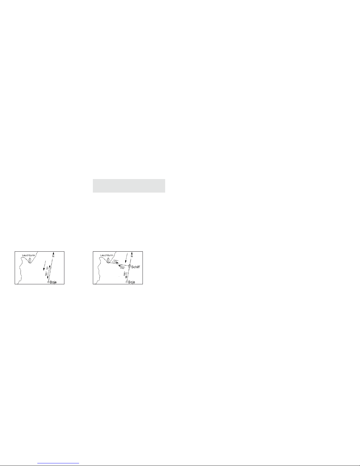
Messen des Azimuten (Horizontalwinkel)
Der Azimut misst den horizontalen Winkel und entspricht der horizontalen Abweichung von Norden.
Anhand des MIL Fadenkreuzes können Sie den horizontalen Skalenwert ablesen. In der Abbildung kann
der Azimut des beobachteten Objektes mit 6 MIL (4
MIL + 2 MIL) einfach mit dem horizontal angeordneten Skalenwert abgelesen werden (siehe Messung des
Elevationswinkels).
Bestimmung der Länge eines Zielobjekts,
wenn die Entfernung bekannt ist
Auf Basis des Elevationswinkels oder Azimuten lässt
sich die Läng e eines Zielobjektes anh and der nachstehenden Formel bestimmen.
Beispiel für die Berechnung der Objektlänge
Die Entfer nung muss als Voraussetzung b ekannt sein.
Diese sei in unserem Beispiel 1.100 Meter. Der auf
der Strichplatte abgelesene horizontale Skalenwert
ergibt 6,0.
Hieraus er gibt sich folgende Rec hnung :
1.100 Meter x 6,0 dividiert durch 100 ergibt eine Objektlänge von 66 Metern.
Azimut = Horizontalwinkel
Objektlänge (m) =
Entfernung des Objekts (m) x Azimut
100
Bedienung des Kompasses
Ihr MINOX BN 7x50 C II verfügt über einen eingebauten analogen Kompass. Dieser gibt die Richtung in
Grad an. Norden hat einen Azimut von 360°, Osten
von 90°, Süden von 180° und Westen von 270°.
Positionsbestimmung mit dem Kompass
Gemäß dem folgenden Beispiel können Sie, in Kombination mit einer Karte und Ihrem Kompass-Fernglas,
Messen des Elevationswinkels
(Höhenwinkel) mit dem vertikalen
Skalenwert auf dem MIL Fad enkreuz
Der Elevationswinkel misst den Winkel zwischen der
horizontal verlaufenden Null-Linie, beginnend vom Ausgangspunkt des Beobachters, hin zum beobachteten
Objekt, und der Höhe eines bestimmten Punktes am
anvisierten Beobachtungsobjekt ( im Bild z.B. der Fuß
des Leuchtturms auf der horizontal verlaufenden NullLinie und die Spit ze des Leucht turms als bestimmter
Punkt). Liegt der Elevationswinkel innerhalb des Bereichs des ver tikalen Skalenwert s von 8 MIL, richten Sie
den im Fadenkreuz vertikal angeordneten Skalenwert
am Fuß des Leuchtturms zunächst auf ‚0‘ aus. Der Elevationswinkel des Leuchtturms im gezeigten Beispiel
lässt sich nun einfach und direkt ablesen und beträgt
im Beispiel 6,7 MIL , wobei 1 MIL 1/1000 Zoll ent spricht.
Liegt der Elevationswinkel des Zielobjekts außerhalb
des vertika len Skalenwerts von 8 MIL , gehen Sie bei der
Bestimmung des Elevationswinkels einfach stufenweise
vor und addieren die schrittweise ermittelten Werte.
Beispiel für die Berechnung der Objekthöhe
Die Entfer nung muss als Voraussetzung b ekannt sein.
Diese sei in uns erem Beispiel 1.194 Met er. Der auf de r
Strichplatte abgelesene Skalenwert sei 6,7.
Hieraus er gibt sich folgende Rec hnung :
1.194 Meter x 6,7 dividiert durch 100 ergibt eine Ob-
jekthöhe von 80 Metern.
Elevationswinkel = Vertikalwinkel
Azimut = Horizontalwinkel
Höhe des Zielobjekts (m) =
Entfernung (m) x Elevationswinkel
100
Länge des Zielobjekts (m) =
Entfernung (m) x Azimut
100
4 42 21 13 3
2
3
4
5
6
7
8
4422
11
33
2
3
4
5
6
7
8
4 42 21 13 3
2
3
4
5
6
7
8
4422
11
33
2
3
4
5
6
7
8
Page 7
12 13
Allgemeine Pflegetipps
Damit Sie über vi ele Jahre Freude und uneing eschränktes Sehvergnügen mit Ihrem MINOX Fernglas haben,
beachten Sie bitte folgende Pflegeempfehlungen.
Fernglas-Tasche im Lieferumfang enthalten
Um Ihr MINOX-Fe rnglas bei Nichtgebrauc h vor Fremdeinflüssen zu schützen, empfehlen wir, das Fernglas
in der mitgelieferten Neopren-Tasche aufzubewahren,
so dass dieses immer geschützt ist.
Reinigen des Fernglases
Bewahren Sie Ihr M INOX Fernglas sauber und t rocken
auf. Vermeiden Sie, es größerer Hitze auszusetzen.
Entferne n Sie Staub und Fremdkörper am G ehäuse mit
einem weichen feuchten Tuch. Wenn Sie Ihr Fernglas
an der See ode r in der Umgebung von Salzw asser benetzt wird, empfehlen wir Ihnen, es nach Gebrauch
mit frischem Was ser abzuspülen. Meeres salz kann mit
der Zeit die Objektivlinsen und optische Qualität Ihres
Fernglases beschädigen.
Reinig ung der O bjekt iv- und Okularl insen
Verunreinigungen wie Staub, Fremdkörper und Fettspuren von Fingerabdrücken beeinträchtigen die
Abbildungsqualität (Bildschärfe und Kontrast) Ihres
MINOX Fernglases. Leichte Verunreinigungen und
Partikel auf den Optiken können mit Hilfe eines weichen Haarpinsels entfernt werden. Stärkere Verunreinigungen oder Fingerabdrücke auf den Linsen lassen
sich mit einem Optikputztuch und speziellem Linsenreiniger entfernen. Wir empfehlen zur Reinigung
Ihres Fernglases die Verwendung des MINOX Optik
Reinigungskits (Best.-Nr. 69731). Weitere geeignete
Optik-Reinigungsmittel erhalten Sie ansonsten auch
im Fachhandel.
Serien-Nummer
Auf der Unter seite eines jeden MINOX Fern glases finden Sie dessen individuelle Fabrikationsnummer. Für
den Verlustfall ist es von Vorteil, diese Nummer zu
notieren und an einem sicheren Ort aufzubewahren.
Ihre Position be stimmen. In Abbildung 3 zei gt der eingezeichnete Pfeil in der Bildmitte die Fahrtrichtung
Ihres Bootes an, also grob in Richtung Süden. Beim
Beobachten durch Ihr Fernglas zeigt der Kompass 190°
zur anvisierten Boje an. Die Differenz zwischen Süden
(180°) und angepeilter Boje (190°) ergibt 190°-180°
= 10°. Dies ist der erste Referenzwert zur Positionsbestimmung. Zur vollständigen Bestimmung Ihrer genauen Position benötigen Sie einen zweiten Referenzwert.
In Abbildun g 4 liegt der eingezeichnete u nd angepeilte
Leuchtturm auf 120° (300°-180° = 120°) des Bootes.
Sie können nun die genaue Position Ihres Bootes auf
der Karte ermitteln, indem Sie die beiden Kurslinien
übereinander legen. Die genaue Position Ihres Bootes
liegt dort, wo sich die beiden Linien kreuzen.
Hinweis: Der Lichtdurchlass für den Kompass (5)
darf nicht mit den Fingern abgedeckt werden, da
sonst keine Anzeige ablesbar ist.
Kompass-Lichtschalter
Um die Kompass- Anzeige auch bei Dunkelheit a blesen
zu können, ist der Kompass Ihres MI NOX BN 7x 50 C II
mit einem Licht schalter ausgestat tet. Bei Drücken des
Lichtschalters wird die Kompass-Anzeige rot hinterleuchtet. Ansonsten verschwindet die Beleuchtung.
Abb. 3 Abb. 4
Page 8

14 15
Gewährleistungsbedingungen
Mit dem Kauf die ses MINOX Fernglases habe n Sie ein
Produkt erworben, das nach besonders strengen Qualitätsrich tlinien hergestellt und gep rüft wurde. Die für
dieses Produkt geltende gesetzliche Gewährleistung
von 2 Jahren wird von uns ab dem Tag des Verkaufs
durch einen autorisierten Händler unter folgenden
Bedingungen übernommen:
1)
In der Gewährleistungszeit werden Beanstandungen, die auf Fabrikationsfehlern beruhen, kostenlos
und nach eigenem Ermessen durch Instandsetzung,
Austausch defekter Teile oder Umtausch in ein
gleichartiges einwandfreies Erzeugnis behoben.
Weitergehende Ansprüche, gleich welcher Art und
gleich aus welchem Rechtsgrund im Zusammenhang
mit dieser Gewährleistung, sind ausgeschlossen.
2) Gewährleistungsansprüche entfallen, wenn der
betreffende Mangel auf unsachgemäße Behandlung – wozu auch die Verwendung von Fremdzubehör zählen k ann – zurückzuführen ist , ein Eingriff
von nicht autorisierten Personen und Werkstätten
durchgeführt oder die Fabrikationsnummer unkenntlich gemacht wurde.
3) Gewährleistungsanspr üche können nur bei Vorlage
eines maschinengeschriebenen Kaufbelegs eines
autorisierten Händlers geltend gemacht werden.
4) Bei Inanspruchnahme der Gewährleistung leiten
Sie bitte das MINOX Fernglas zusammen mit dem
Original des maschinengeschriebenen Kaufbelegs
und einer Schil derung der Beanstandu ng dem Kundendienst der MINOX GmbH oder einer Landesvertretung zu.
5) Touristen steht im Bedar fsfalle unter Vorlage des
maschinengeschriebenen Kaufbelegs die Vertretung des jeweiligen Reiselandes gemäß den Regelungen zur Gewährleistung der MINOX GmbH
zur Verfügung.
Erweiterter MINOX Garantieservice
Nutzen Sie die Möglichkeit der erweiterten MINOX
Produktgarantie und registrieren Sie Ihr MINOX Produkt. Er fahren Sie mehr unter ww w.minox.com/s ervice.
Tipps zur Benutzung des Fernglases
Setzen Sie Ihr MINOX-Fernglas niemals über längere
Zeit starker Hit ze aus. Dies könnte Schäden an der
Armierung oder den Augenmuscheln Ihres Fernglases hervorrufen. Vermeiden Sie insbesondere Orte wie
das Armaturenbrett oder die Hutablage eines Autos
zur Aufbewahrung Ihres Fernglases. Diese sind zur
Aufbewahrung keinesfalls geeignet, da sich die Sonneneinstrahlung hinter einer Scheibe extreme Temperaturen erzeugt, bei denen Ihr Fernglas beschädigt werden kann. Um Fallschäden zu vermeiden, benutzen
Sie stets den mitgelieferten Trageriemen. Entfernen
Sie sich niemals, wenn das Fernglas auf einem Stativ
montiert ist. Demontieren Sie stets das Fernglas, bevor Sie außer Reic hweite des Stativs gehen. Be wahren
Sie Ihr Ferngla s für längere Zeit in der mitgelieferten
Tasche an einem temperierten und trockenen Ort auf.
Technische Daten
Vergrößerung 7-fach
Prismensystem Porro
Kompass analoger Kompass,
analoge Strichplatte
Objektivdurchmesser 50 mm
Austrittspupille 7,14 mm
Sehfeld auf
1.000 m / 1.000 yards 131 m / 393 ft.
Dioptrienausgleich - 4 / +6 Dioptrien
Pupillenschnittweite 21 mm
Geom. Lichtstärke 51
Dämmerungszahl 18,7
Funktionstemperatur -10 °C bis +50 °C
Wasserdicht schwimmfähig,
druckwasserdicht bis
3 m Tiefe (0,3 bar)
Höhe x Breite x Tiefe 163 x 223 x 78 mm
Gewicht ca. 1.010 g
Bestell-Nummer 62256
Page 9

16 17
Introduction
Congratulations!
With the purchase of these MINOX binoculars you
have acquired a pr oduct that has been manufac tured
to the highest optical standard with high precision
mechanics . These instructions ar e to help you benefit
from the full performance range of your MINOX
binoculars.
Enjoy your new MINOX product!
Get to know your binoculars
• Porro prism binoculars
• Individual eyepiece adjustment
• Buoyant, waterproof down to 5 meter ( 0,5 bar)
• No fogging up and nitrogen-filled
• Sturdy, lightweight Makrolon body
• Non-slip rubber armoring
• Analog compass with illuminator and
analog reticle plate
• Diopter correction from – 4 to + 6 diopters
Controls
(see also illustration on page 2)
1. Folding eyecups
2. Eyepiece ring
3. Neck strap bracket
4. Compass housing
5. Light opening
6. Compass illuminator switch
7. Tripod thread cap screw
8. Battery compartment
9. Battery compartment cover
10. Objective
11. Eyepiece cap
12. Loop for fastening the neck strap
13. Objective lens cap
14. Bracket for objective lens cap
Warning : As with all binoculars, do not use your
MINOX binocula rs to look at the sun or other sou rces of bright light in order to prevent any eye injury.
Content
Introduction 17
Get to know your binoculars 17
Controls 17
General instructions 18
Preparing your binoculars 18
- Attaching the neck strap 18
- Attaching the eyepiece cap 18
- Objective lens cap 18
- Adjusting the binoculars 19
- Interpupillary distance adjustment 19
- Foc using 19
- Using the binoculars with
and without eyeglasses 19
- Attachment to a tripod mount 20
Inserting and changing the batteries 20
Distance measurement 21
- Using the MIL crosshairs for distance
measurement (telemetry system) 21
- Measuring the elevation angle 22
- Measuring the azimuth (horizontal angle ) 23
- Using the compass 23
General care recommendations 25
- Binocular case included in scope of delivery 25
- Cleaning your binoculars 25
- Cleaning the objective lenses
and eyepiece lenses 26
- Serial number 26
Technical Data 26
Helpful advice on the use
of your binoculars 26
Conditions of warranty 27
Exten ded MINOX War ranty Se rvice 27
Page 10

18 19
Adjusting the binoculars
Your MINOX BN 7x50 C II should be adjusted to your
individual needs before use. Observe the following
steps for correct use.
Interpupillary distance adjustment
Your MINOX BN 7x50 C II ha s a folding bridge that you
can use to adjust the two eyepieces to the distance
between yo ur eyes. Your MINOX BN 7x50 C II is properly adjusted to the interpupillary distance when you
can see one round full circle when you look through
your MINOX binoculars. Adjust your MINOX binoculars until the t wo circles are superimposed to form
one full circle.
Focusing
Your MINOX BN 7x50 C II has an individual eyepiece focusing system. The advantage of this
feature is that all observed objects within a range
from 12 meters to infinity can be seen as a pin sharp
image withou t having to readjust the focusin g of your
binoculars to close or far away objects. The adjust
able range of the individual eyepieces is – 4 up to + 6
diopters.
Proceed as follows to ensure optimum adjustment to
your vision: Choose an observation object at a distance of about 50 meters.
First close your right eye. Look through the left
eyepiece of your binoculars with your left eye.
Turn the left eyepiece ring in clockwise or counterclockwise d irection until you see a shar p image. Now
close your lef t eye and adjust the right eyepiece in
the same way by turning the right e yepiece ring. Your
binocular is now adjusted to your individual vision.
Both eyepieces have a diopter scale. Remember your
individual diopter setting for the left and right eyepiece or mark it with a permanent m arker. In this way
you will be able to quickly readjust the binoculars to
your vision if, for example, another person has used
them and changed the settings.
Using the binoculars with
and without eyeglasses
Your MINOX BN 7x50 C II is fitted with folding eyecups of flexible rubber. These can be used to adjust
the distance to your eye, depending on whether you
are wearing glasses or not. Those users not wearing
glasses leave t he folding eyecups in exte nded position
General instructions
Preparing your binoculars
The scope of delivery of your MINOX BN 7x50 C II includes a neoprene neck strap. We recommend that
you wear the nec k strap whenever you are using yo ur
MINOX binoculars.
Note: By wearing the strap you can avoid damage
caused by dropping the binoculars.
Attaching the neck stra p
Thread the st rap through the bracket (3 ) on the body
of the binocular s. Pull the end of the strap ba ck to the
buckle and the n thread it through the buckl e from behind to secure the strap. Fasten th e neck strap on the
other side of the binoculars in the same way. Adjust
the neck stra p to a comfortable leng th once you have
fastened it on both sides.
Attaching the eyepiece c ap
Connect th e eyepiece cap (11) to the neck strap via t he
loop (12) on the left side. The eyepiece cap protects
the optics on the eyepieces against foreign particles ,
rain, dust and sand. Remove the eyepiece cap from
the eyepiece when you want to use your binoculars.
This cap then hangs down out of the way on the left
side of the strap.
Objec tive len s cap
Use the objec tive lens cap (13) to protec t the objective
lenses of the BN 7x50 C II against foreign particles,
rain, salt water, dust and sand. You can attach this
lens cap to your b inoculars by placing the loo p on the
objective lens cap bracket (14) over the cap screw of
the tripod t hread (7) and threading i t through until the
loop is completely inserted behind the tripod thread.
Remove the lens cap from the objective lens when
you want to use your bi noculars and let it hang down.
If you want to remove the lens cap from your
BN 7x50 C II completely, pull the loop of the lens cap
bracket carefully out from behind the tripod thread
and pull the loop off the cap screw of the tripod
thread (7).
Page 11

20 21
Distance measurement
Using t he MIL cr ossha irs for distance
measurement (telemetry system)
With the MINOX BN 7x50 C II you can use the analog
reticle plate (crosshairs ) to determine the distance
of observed objects. Distance measurement can be
carried out w ith the aid a simple equation, as l ong as
the height or le ngth of the observed ob ject are known
with sufficient accurac y: in practice the size (height/
length) i s usually known because th e observed object s
are mostly people, buildings or vehicles.
Examp le for cal culat ing the distance
The height of the lighthouse is 80 meters. The value
read off the reticle plate is 6.7.
This is the n calcula ted as follow s:
100 x 80 meters d ivided by 6.7, resulting in a distance
of 1,194 meters.
Fig. 1 Fig. 2
Elevation angle = Vertical angle
Azimuth angle = Horizontal angle
Distance (in m) =
Height of observed object (m) x 100
Elevation angle of observed object
Distance (in m) =
Length of observed object (m) x 100
Azimuth angle of observed object
(as purchase d) when looking throu gh the binoculars.
In this condition the pupil of your eye is at the
correct distance to the ocular lens. This adjustment
also ensures a steady positioning of the binoculars
against the eye and minimizes stray light. When
looking through your MINOX BN 7x50 C II wearing glasses you must fold down the rubber
eyecups to enable you to see the entire field of view
right into the edges.
Warning : Do not use you r MINOX binoculars to look
at the sun or othe r bright sources of light to pr event
any eye injury.
Attachment to a t ripod mount
To ensure steady and fatigue-free viewing you can
mount your MIN OX BN 7x50 C II on a tripod using t he
tripod thread integrated in the body. For this purpose we recommend the MINOX tripod mount ( order
number 69727) that is available from our range of
accessories.
To use the tripod mou nt first remove the cap scre w (7)
from the tri pod thread on the undersi de of the MINOX
BN 7x50 C II. Connect the MIN OX tripod mount to the
thread turning it in clockwise direction.
Keep the cap screw (7) in a safe place and screw it
back into the tripod thread af ter removing the tripod
mount.
Inser ting and chang ing the b atteri es
Your MINOX BN 7x50 C II has a c ompass with a display
that can be illuminated in the dark at the press of a
button. For this the compass requires two batteries
of the type LR 43.
To insert or replace the batteries proceed as follows:
1. Open the screw cap on the battery compartment
on the bottom of the binoculars by turning it in
counterclockwise direction (Fig.1)
2. Take the old batteries out of the battery compartment. (F ig. 2) and insert two new b atteries of type
LR 43 in the battery compartment (pay attention
to correct poling).
3. Tighten t he screw cap on the batte ry compartment
again by turning it in clockwise direction.
4 42 21 13 3
2
3
4
5
6
7
8
4422
11
33
2
3
4
5
6
7
8
Page 12

22 23
Measu ring the a zimuth (hor izonta l angle )
The azimuth measures the horizontal angle and corresponds to the horizontal deviation from the north.
Using the MIL crosshairs you can read off the horizontal scale value. In the illustration the azimuth of
the observed object at 6 MIL (4 MIL + 2 MIL) can be
simply determined using the horizontal scale value
(see measurement of elevation angle).
Determ ining the lengt h of an observed
object when the distanceis known
On the basis of the measured elevation angle or azimuth angle the h eight or length of an obser ved object
can be determined using the following equation:
Examp le for cal culat ing the object le ngth
It is a preprequisite to know the distance. In our example this is 1,100 meters. The scale value read off
the reticle plate is 6.0.
This is the n calcula ted as follow s:
1,100 meters x 6.0 divided by 100, resulting in an
object length of 66 meters.
Using the compass
Your MINOX BN 7x50 C II has an integrated analog
compass that shows the bearings in degrees. North
has an azimuth angle of 360°, east is 90 °, south is
180° and west has an azimuth angle of 270°.
Determ ining your posit ion wit h the comp ass
With the following example your can determine your
position using a map and your compass binoculars.
Azimuth angle = Horizontal angle
Length of observed object (m) =
Distance (m) x azimuth angle
100
Measu ring the e levation angle
(vert ical an gle) with the vertica l
scale re ading on the MIL c rosshairs
The elevation angle measures the angle between the
horizontal zero line, beginning at the starting point
of the observer and extending towards the observed
object, and the height of a defined point on the
observe d object (in the illustrat ion e.g. the base of the
lighthouse on the horizontal zero line and the top of
the lighthou se as defined point) . If the elevation angle
is within the range of the vertical scale of 8 MIL, you
must first align the vertical scale in the crosshairs at
the foot of the lighthouse to “0”. The elevation angle
of the lighthou se in the illustrated example c an now be
read off dir ectly as 6.7 MIL, where in 1 MIL corresponds
to 1/1000 inch. If the elevation angle of the observed
object lies outside of the vertical scale of 8 MIL, to
determine t he elevation angle you must simp ly proceed
in steps and ad d up the individually deter mined values.
Examp le for cal culat ing the height
of the object
It is a prerequi site to know the distance. This is 1,194
meters in our e xample. The scale value read f rom the
reticle plate is 6.7.
This is the n calcula ted as follow s:
1,194 meters x 6.7 divided by 100, resulting in an
object height of 80 meters.
Elevation angle = Vertical angle
Azimuth angle = Horizontal angle
Height of observed object (m) =
Distance (m) x elevation angle
100
Length of observed object (m) =
Distance (m) x azimuth angle
100
4 42 21 13 3
2
3
4
5
6
7
8
4422
11
33
2
3
4
5
6
7
8
4 42 21 13 3
2
3
4
5
6
7
8
4422
11
33
2
3
4
5
6
7
8
Page 13

24 25
General care recommendations
Follow the following care recommendations to ensure
maximum enjoyment and excellent viewing for many
years with your MINOX binoculars.
Binocular case included in scope of delivery
To protect your binoculars when not in use or when
traveling we recommend that you keep them in the
provided neoprene case.
Cleaning your binoculars
Keep your binoculars clean and dry. Avoid exposure
to excessive heat. Remove dust and foreign particles
from the bod y using a soft damp cloth. If y ou are using
your binoculars at sea or near salt water we strongly
recommend rinsing them off with fresh water after
use. Over time, sea salt can damage the objective
lenses and the optical qualit y of your binoculars.
Cleaning the objective lenses
and eyepi ece lenses
Contamination such as dust, foreign particles and
grease from fingerprints impairs the imaging quality
(sharpness and contrast ) of your MINOX binoculars.
Remove minor soiling and particles on the lenses us-
ing a soft brush. More severe soiling or fingerprints
on the lens sur faces can be removed using an d optical
lens cloth and lens cleaner solution. We recommend
the MINOX Opt ical Cleaning Kit (orde r number 69731)
for cleaning your binoculars. Other suitable optical
cleaning solutions can also be purchased from specialist dealers.
Serial number
On the bott om of every pair of MINOX binocu lars you
will find the “indiv idual“ serial number. It is import ant
to make a record of this number and keep it in a safe
place in case of any loss.
In the illustration (Fig. 3 ) the arrow in the middle
indicates the boat’s direction of travel, in this case
roughly due south. When you look through your
binoculars the compass shows the observed buoy at
190°. The difference between South (180° ) and the
observed buoy (190°) is 190° - 180° = 10°. This is
your first reference value for position determination.
To complete the dete rmination of your exact posi tion
you need a second reference value. In the following
illustration ( Fig. 4) the indicated and observed lighthouse is at 120° (30 0° - 120°) f rom the boat. You can
now determin e your boat ’s exact position on the map
by superimposing the two course lines. Your boat’s
position is exactly where the two lines cross.
Note: Do not cover the light opening for the compass (5) with your fingers, as you with otherwise
not be able to read the bearings.
Compass illuminator switch
The compass of your MINOX BN 7x50 C II has an illuminator switc h so that you can also read the com pass
in the dark. When you press the switch the compass
display has a backl ight in red. There is no illuminat ion
when the switch is not pressed.
Fig. 3 Fig. 4
Page 14

26 27
Conditions of warranty
With the purchase of this MINOX product you have
acquired a pro duct which has been manuf actured and
checked to spec ial quality standards . For this product
the MINOX GmbH provides warranty of 2 years. The
period commences on the date of purchase from an
authorized dealer and the warranty is subject to the
following conditions:
1) During the warranty period we shall deal with
complaints based on faulty manufacture (free of
charge) by repair, replacement of defective parts
or replacement by an identical flawless product
at our own discretion. Consequential claims, no
matter what kind of what legal argument in
connectio n with this warranty, cannot b e accepted.
2) Claims under warranty are null and void, if the
defect has been caused by improper handling –
which also can include the use of non-MINOX
accessories – if the MINOX product is serviced by
unauthorized persons or workshops, or if the serial
number has been obliterated.
3) Warrant y claims can only be made by submi ssion of
the typewritten sales slip of an authorized dealer.
4) When submitting claims under warrant y please
return the MINOX product together with the typewritten sales slip and a description of the claim to
the MINOX GmbH or MINOX agency.
5) Tourists may, if required, make use of the Agency
of the countr y in which they are travelling (within
the terms of the Warranty of th e MINOX GmbH) by
presenting the typewritten sales slip.
Extended MINOX Warranty Service
Take advantage of the e xtended MINOX produ ct warranty and register your MINOX product. Find out more
at www.minox.com/service.
Helpful advice on the use
of your binoculars
Never expose your binoculars to severe heat for prolonged peri ods. This can cause damage t o the armoring or to the eyecups.
Avoid places such as the dashboard or the rear shelf
in motor vehicle s for storing binoculars. T hese places
are not suitab le as exposure to the sun dire ctly behind
glass causes extremely high temperatures that can
damage your binoculars.
Always use the p rovided neck strap and avoi d damage
caused by dropping the binoculars.
Never walk away when the binoculars are mounted
on a tripod.
Always remove the binoculars before moving out of
the tripod range.
Keep your binoculars in the provided case in a dr y
place and at a moderate temperature if you are not
using them for any length of time.
Technical Data
Magnification 7 x
Prism system Porro
Compass analog compass,
analog reticle plate
Lens diameter 50 mm
Exit pupil 7.14 mm
Field of view at
1,000 yards / 1,000 m 393 ft. / 131 m
Diopter correction - 4 / +6 Dioptrien
Eye relief 21 mm
Brightness index 51
Twilight number 18,7
Operating temperature -10 °C up to +50 °C
Watertight buoyant, waterproof down
to 10 ft. / 3 m (0.3 bar)
Height x Width x Depth 163 x 223 x 78 mm
Weight approx. 35.6 oz / 1,010 g
Order number 62256
Page 15

Änderungen in Konstruktion und Ausführung vorbehalten.
Die Marke MINOX ist eine eingetragene Marke der MINOX GmbH, Wetzlar.
Design subject to alterations without notice.
MINOX is a registered trademark of MINOX GmbH, Wetzlar.
MINOX GmbH
Walter-Zapp-Str. 4
D-35578 Wetzlar, Germany
Tel.: +49 (0) 6441 / 917-0
Fax: +49 (0) 6441 / 917-612
E-Mail: info@minox.com
www.minox.com
www.minox.com/facebook
www.youtube.com/minoxwebcasts
9988001 12/17 wmd
 Loading...