

Page 1
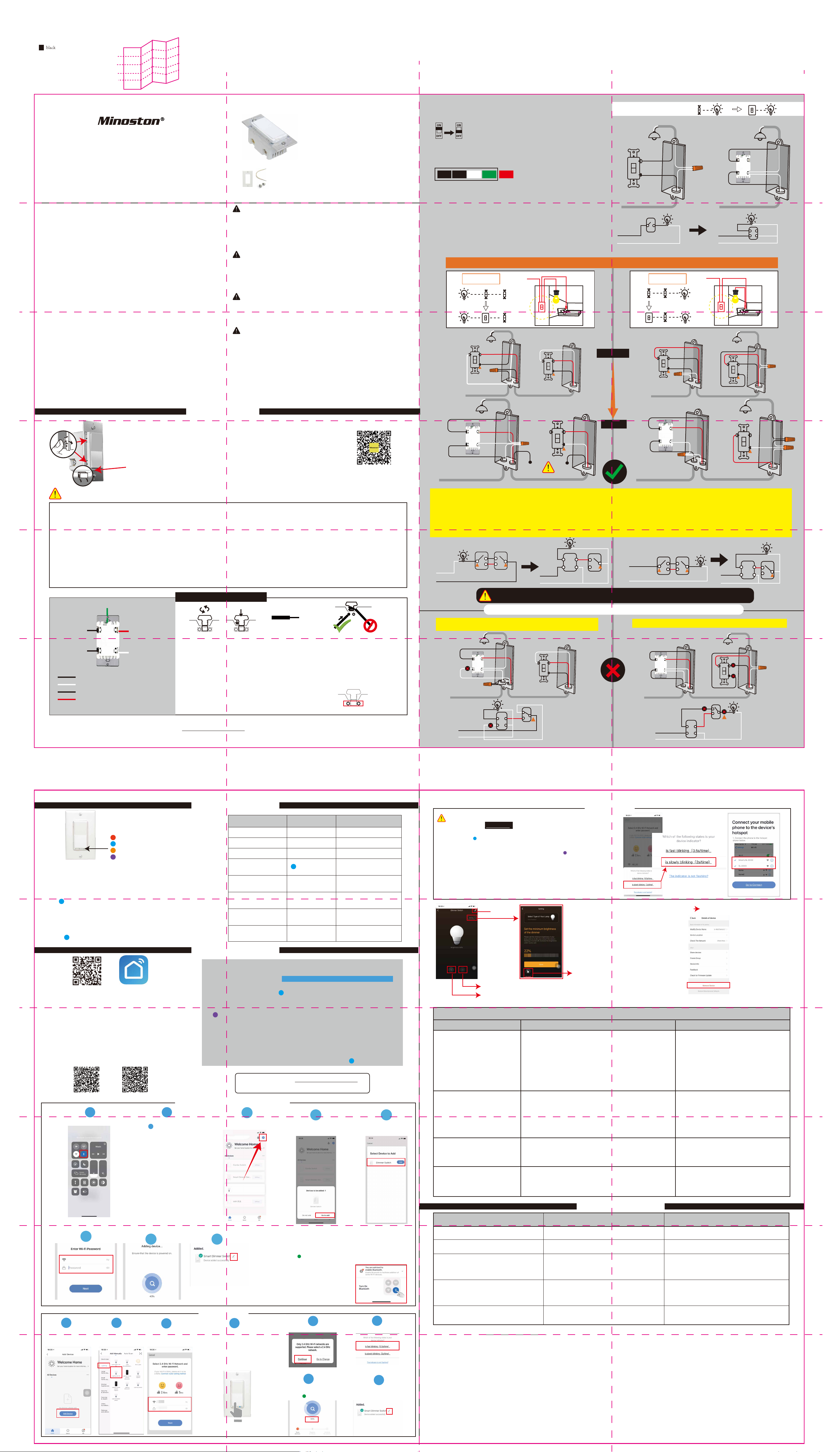
SIZE: 440 x 373 mm
材质:80G 书写纸
拆法:风琴页 110 x 62 mm 成品
V2.0 2020.03.09
V3.0 2020.07.20
正面
Wi-Fi Smart Dimmer Switch
• MS10W •
FCC
This device complies with part 15 of the FCC and Industry Canada
license-exempt RSS standard(s). Operation is subjected to the following two
conditions:
(1) this device may not cause harmful interference, and (2) this device must
accept any interference received, including interference that may cause
undesired operation.
FCC NOTE: The manufacturer is not responsible for any radio or TV interfer-
ence caused by unauthorized modifications to this equipment. Such
modifications could void the user’s authority to operate the equipment.
— Reorient or relocate the receiving antenna.
— Increase the separation between the equipment and receiver.
— Connect the equipment into an outlet on a circuit different from that to
which the receiver is connected.
— Consult the dealer or an experienced radio/TV technician for help.
NOTE: This equipment has been tested and found to comply with the limits
for a Class B digital device, pursuant to Part 15 of the FCC Rules. These limits
are designed to provide reasonable protection against harmful interference
in a residential installation. This equipment generates, uses and can radiate
radio frequency energy and, if not installed and used in accordance with the
instructions may cause harmful interference to radio communications.
However, there is no guarantee that interference will not occur in a particular installation. If this equipment does cause harmful interference to radio
or television reception, which can be determined by turning the equipment
off and on, the user is encouraged to try to correct the interference by one or
more of the following measures:
Important note: To comply with the FCC RF exposure compliance requirements, no change to the antenna or the device is permitted. Any change to
the antenna or the device could result in the device exceeding the RF
exposure requirements and void user’s authority to operate the device.
Specifications:
Power: 120VAC, 60Hz
Wireless Frequency: 2.4GHz
Wireless Standard: IEEE802.11b/g/n
Maximum Load:
500 W incandescent, 150W LED
• Switch x1
• wiring x1
• screws x2
• Faceplate x1
CAUTION - PLEASE READ!
This device (MS10W) is intended for installation in accordance with the
National Electric Code and local regulations in the United States, or the
Canadian Electrical Code and local regulations in Canada. If you are unsure or
uncomfortable about performing this installation consult a qualified
electrician.
WARNING - SHOCK HAZARD
TURN OFF THE POWER to the circuit for the switch and lighting fixture
at the service panel (circuit breaker) prior to installation.
ALL WIRING CONNECTIONS MUST BE MADE WITH THE POWER OFF to
avoid personal injury and/or damage to the switch.
OTHER WARNINGS
Risk of Fire
Risk of Electrical Shock
Risk of Burns
WARRANTY
Our Products warrants this product to be free from manufacturing defects
for a period of one year from the original date of consumer purchase. This
warranty is limited to the repair or replacement of this product only and
does not extend to consequential or incidental damage to other products
that may be used with this product. This warranty is in lieu of all other
warranties, expressed or implied. Some states do not allow limitations on
how long an implied warranty lasts or permit the exclusion or limitation of
incidental or consequential damage, so the above limitations may not apply
to you. This warranty gives you specific rights, and you may also have other
rights which vary from state to state.
(300W with both sides of heat sink tabs off)
Minimum Load: 5W for LED bulbs
For indoor use.
1. Tool: Please prepare a flat head screwdriver.
2.
Turn power OFF at circuit breaker or fuse box.
3. Remove wallplate.
4. Remove the switch mounting screws.
5. Disconnect the wires and label them aer remove the old
switch.(Please use our sticker)
Traveler
Line
Load
GroundNeutral
(Just for 3-way switch)
6. Carefully remove the switch from the switch box. (DO NOT
disconnect the wires.)
7. There are up to five screw terminals on the smart switch,
these are marked (Please check <HOW TO INSTALL THE
WIRES>)
8. Fix the wallplate with screws aer wiring succeed. (Please use
our screws.)
9.The Ground was excluded from the diagram to simplify the
illustration. Please Make sure all ground wires are connected to
all switches respectively.
Please check which option is best for your 3-way installation.
Option 1
Power
regular
From breaker box
Single-pole wiring
From breaker box From breaker box
Line
Neutral
Option 2
From breaker box
Line
Neutral
Power
Part 1. Installation
CHANGING THE COLOR OF THE PADDLE(OPTIONAL)
This step is optional. Before you start you may want to change the color of the paddle to match
your wallplate or decor.
1. Push side tabs in on one side and then the other to release paddle. Li the cover up and off.
2. Simply put the new paddle onto the switch by side tabs and snap securely into place.Once
this step has been completed please proceed to part 2 wiring.
Air-Gap Switch:
The "air gap switch" will cut power to the device if it's pulled up. It's located right below the
main switch itself, oen next to the LED. Pull up for Bulb replacement, push down for
normal use.
Wiring Instructions - A Few Quick Reminders
Please do not try installing this device if you are unsure of how electrical circuits operate. Cause it can be dangerous and even life-threatening if you do
not install this correctly. Please consult a qualified electrician if necessary. With that said, here are a few other warnings we’d like to point out for your
safety:
Note before installation
1. The Wi-Fi In-wall Smart Switch must not exceed 150W LED, 500W incandescent.
2. The switch is designed only for use with permanently installed fixtures.
3. The wall box required: 1-gang U.S. wall box. 3½ in deep recommended, 2¼ in deep minimum.
4. Work with regular 3-way on/off for 2 locations control. It can only be connected with regular 3-way on/off switch, don't use a smart switch or a
dimmer switch! Couldn't work with an add-on switch!
5. The colors of your wires may not match the ones in our diagrams so please make sure you've identified all wires correctly based on their source,
not color only.
6. This switch requires a Neutral for installation, or the installation will not succeed.
7. Not recommended for fan.
Scan to view installation guide
smart
From breaker box
1) Neutral required. If the switch box do not have a Neutral, please stop! Connect the white wire to neutral terminal (use a white jump wire form the
package or the second hole at the terminal to connect.)
2) Insert the Line wire to Line terminal and Load wire to Load terminal. LOAD and LINE Can’t be swapped, please make sure to identify them correctly!
3) Install the smart switch in the switch box which directly connects to the power Line, Load and Neutral.
4) Only work with regular 3-way on/off for 2 locations control. It can only be connected with regular 3-way on/off switch, don't use a smart switch or a
dimmer switch! Couldn't work with an add-on switch!
Neutral
Line
common
common
None-connection
Line
Neutral
Smart
Switch
common
From breaker box
Line
Neutral
common common
Line
Neutral
Smart
Switch
common
Ground
Load
Line
Line (hot) — black (connected to power)
Neutral — white
Load — black (connected to lighting)
Traveler — red/other
(only in 3-way installations)
Traveler
Neutral
• Please contact us at [email protected] if you have any questions during installation.
HOW TO INSTALL THE WIRES
1.
1. Unscrew: carefully turn the screw counterclockwise to leave enough space for
the wire to be inserted. Do not unscrew the screws completely.
2. Press down: Once loosened, use your finger so it catches the thread.
3. Insert the wire: make sure the wire is completely straight, then insert it into the
terminal while holding down the screw. Do not wrap the wire around the screw!
4. Tighten: Turn the screw clockwise to tighten the wire. Make sure the
wires are locked!
Note: There are 2 holes for each terminal can be used in the
connection.You can use a jump wire or the second hole at the
terminal to connect.
2.
3.
STRIP WIRE AT 3/8-1/2”
4.
Please change the wiring of the regular switch to make the 3-way configure works properly.
When the smart switch does not work properly, there may be in error conditions:
1) Make sure the Neutral wire of the smart switch is correctly connected.
2) The wiring of this regular switch has not changed.
From breaker box
Line
Neutral
The wiring of this regular switch has not changed.
From breaker box
Line
Neutral
反面
LED Indicator:
Red: Network failure
Blue: Network configuration mode
Orange: Light status indicator
Purple: AP Network configuration mode
OPERATION GUIDE
• Adding your device to Wi-Fi network:
Please make sure the switch is on the "OFF" position.
Hold the “down” button more than 10s until the bulb flashes and
blue LED indicator blinks rapidly to initiate App-configured Mode.
• If you need to reset the device ( Factory setting)
Network reset
1.Turn off the light(when the light is on)
2.Hold the “down” button more than 10s until the bulb flashes
( blue LED indicator blinks rapidly)
Part 2. Manual Control
Operation LED Switch
Press “down ” ON ( Default ) Power OFF
Press “up” OFF (Default) Power ON
Hold / Dimmer up or dimmer down
Hold the “down” button
more than 10s
Press the “down” button
5 times qucikly
Press the “up” button
5 times quickly
Press the “up” button
8 times quickly
Press “down ” button
8 times quickly
Part 3. APP Connection
blue LED flashes Connect to the network
flash 3 times Change LED status
flash 3 times
flash 3 times
flash 3 times
Restores status
aer power failure
Output off State Setting
Button Function Setting
AP Mode
If you cannot successfully configure the default mode, try
connecting to AP mode.
1 ) Click on "AP Mode" in the upper right corner.
2 ) When the blue LED indicator flashes quickly, press and hold the
off button (default is the down button) for more than 5s until the
bulb flashes twice to enter the AP mode, and the purple LED
indicator flashes quickly.
3 ) Click "Confirm light flashes."
4 ) Enter Wi-Fi network password.
5 ) Open wireless WLAN settings with "SmartLife-xxxx".
6 ) Back in the application, continue adding devices and wait for the
connection to complete.
Edit
Setting
SETTING
For better performance of the LED, please set
a minimum brightness value. When the bulb
is at this minimum brightness value, the bulb
does not flicker. The minimum brightness of
different bulbs may be different.
Edit
Remove Device
QR code Smart Life
1. Please scan the QR code to download the application
“Smart Life”.
2. If you cannot download the Smart Life app, please search
“Smart Life” on Google Play (for Android phone) or Apple
Store (for iOS phone) to download.
Aer you download the Smart Life App and register a new account,
please follow the instructions below to set up your smart switch.
3. The smart switch can be also used with Amazon Echo and
Google Home. Please scan the QR code below and follow
the instructions if you have any trouble pairing with them.
Amazon-Echo Google-Home
1 2
Turn on your Phone bluetooth.
The auto-connection comes
with blue LED indicator
blinks for 3 minutes to wait
for configuration. If it
stopped, please Hold the
“down” button more than
10s until the bulb flashes and
the blue LED blinks again.
Note:
1)Our products only support 2.4GHz Wi-Fi network.
2) 3 connection network modes: Bluetooth quick-fit Mode, Easy Mode, AP Mode.
Choose the most suitable mode to configure the network.
3)Please operate quickly when blue LED indicator blinks rapidly.
4) When indicator flash enters the network, complete standard operation within
30s
5) Purple LED Flashing slowly enters AP Mode (select “AP Mode” follow the
below instructions.)
6) Make sure the switch works properly by manual control before network
configuration.
• Device Reset / Network reset
step 1: turn off the light (when the light is on)
step 2: hold the “Down” button until the light bulb flashes ( LED blinks rapidly)
• Please contact us at [email protected]
if you have any questions during installation.
Bluetooth Quick-Fit Mode
3
Tap ‘+’ to add this switch
in the “Smart Life” APP.
You'll see “Devices to be
added”---“Go to add”.
4 5
Click to “Add ”
Set a timer to the switch.
Adjust the brightness of the light.
Parameter Available settings Operation
Parameter 1:
LED Indicator Status Setting-
This parameter can access you to
choose the led indicator to be on
when the switch(light) is on/off, or
LED indicator remains on/off all
times.
Parameter 2:
Restores State aer Power
Failure
This parameter can access you to
set the switch to be on/off aer
power failure.
Parameter 3:
Light off State Setting
This parameter can access you to
set the light fade out or off
immeditaly.
Parameter 4:
Button Function Setting
This parameter can access you to
set the up button to turn the light
on/off.
Locks for the minimum value
The indicator will flashes 3 times aer each parameter set successfully
Value=1 (default)
Orange LED is On when the switch(light) Off and Orange LED is
Off when the switch (light) On.
Value=2
Orange LED is On when switch(light) On and Orange LED is Off
when the switch(light) Off.
Value=3
Orange LED is always Off.
Value=4
Orange LED is always On.
Value=1
The switch is off regardless of the state prior to power failure.
Value=2
The switch is on regardless of the state prior to power failure.
Value=3 (default)
memory state before power failure
This switch will be return to state prior to the power failure
aer power is restored.
Value=1 (default)
Fade out
Value=2
Instantaneous off
Value=1 (default)
The up button turn the light on and down button turn lights off.
Value=2
The up button turn the light off and down button turn lights on.
Quick press “Down” button 5 times.
Please note: the switching of each value is in
order, a quick press “Down” button 5 times
will switch once. eg: Switching from value1 to
value 4 needs 3 switchings.
Quickly press “Up” button 5 times.
Please note: the switching of each value is in
order, a quick press “Up” button 5 times will
switch once. eg: Switching from value1 to
value 3 needs 2 switchings.
Quick press “Up” button 8 times
Please note: the switching of each value is in
order, a quick press “Up” button 8 times will
switch once. eg: Switching from value1 to value
Quick press “Down” button 8 times
Please note: the switching of each value is
in order, a quick press “Down” button 8
times will switch once. eg: Switching from
value1 to value 2 needs 1 switching.
2 needs 1 switching.
6
1 2
Tap ‘+’ to add a
device in your app
Select “Lighting ”-
“Lighting (Wi-Fi)”
7 8
Easy Mode
3
Enter the Wi-Fi
Password
Hold the “down” button more
than 10s until the light bulb flashes
and
“BLUE”
Please make sure the switch is on
the "OFF" position.
6: Enter the Wi-Fi Password (Your phone should have
connected to the same Wi-Fi first).
7: Wait for the app to connect to your Wi-Fi until it’s 100%.
(LED stays in green 3 secotnds.)
8: Edit the name of your new smart plug!
Note: When the Bluetooth is off,
4
LED blinks rapidly.
APP will remind: “You are
advised to enable Bluetooth”.
5
Click to “Continue ”
Select “is fast blinking(0.5s/time)”
7
Wait for it’s 100%
(LED stays in green 3 seconds.)
6
8
Click and edit the name of switch!
Part 4. Troubleshooting
Possible Problem Possible Cause Solution
• Unable to connect with the phone
• The light bulb blinks when the switch
turn it off
• Cannot turn the switch on/off
manually
• The switch is not work with APP
control
• The switch cannot connected to the
application
Please contact us at [email protected] if you have any questions during installation.
Network issue.
There is a leakage of electricity or the bulb
does not close with the switch
1. Incorrect wiring
2. No electricity
3. The bulb is broken or incompatible
1. Network delay or disconnect
2. The phone refuses your permission
3. The switch out of the order
1. Enter wrong Wi-Fi password
2. Weak Wi-Fi signal
3. Unable to connect to Wi-Fi
Please check if the red LED blinks. If yes, retry to
add this switch to your network.
Rewire the switch or replace the bulb.
• Make sure the switch wiring is correct
• Inspecting circuit breakers; Make sure the
power supply is restored
• change a light bulb
• Check your network connectivity, The
switch needs to be reconnected
• Grant permission on your phone settings
• Manually switch on to check the switch
• Enter the correct Wi-Fi password
• Check Wi-Fi signal
• Confirm Your Wi-Fi is 2.4GHz
V3.0
 Loading...