

Page 1
FrameMaker Ver.5.5(PC) Di350 SWITCHES ON PWBs/TECH. REP. SETTINGS
98.11.25
Di350
SWITCHES ON PWBs,
TECH. REP. SETTINGS
17196
Page 2

FrameMaker Ver.5.5E(PC) Di350 SWITCHES ON PWBs/TECH. REP. SETTINGS
98.11.25
CONTENTS
1. PRECAUTIONS FOR HANDLING THE PWBs ................................................S-1
1-1. Precautions for Transportation and Storage ............................................S-1
1-2. Precautions for Replacement and Inspection ..........................................S-1
2. CONTROL PANEL KEYS AND TOUCH PANEL .............................................S-2
2-1. Control Panel Keys ..................................................................................S-2
2-2. Explanation of the Touch Panel ...............................................................S-3
(1) Basic Screen ...................................................................................S-3
(2) Warning Screens .................................. ............... ............... .............S-4
3. FUNCTION OF SWITCHES AND OTHER PARTS ON PWBs ........................S-5
3-1. PWB Location .......................................................................................... S-5
3-2. PWB-A (Master Board) ............................................................................S-5
3-3. UN1 (Control Panel) .............................................. ..................................S-6
3-4. PWB-L (PPM Switching Board) ....................................... ........................S-6
3-5. UN2 (MFB Board) ....................................................................................S-7
4. USER’S CHOICE MODE .................................................................................S-9
4-1. User’s Choice Selection Screen ..............................................................S-9
4-2. User’s Choice Function Setting Procedure ..............................................S-9
4-3. User’s Choice Function Tree ...................................................................S-10
4-4. Settings in the User’s Choice Mode ...................................................... ...S-11
5. TECH. REP. MODE ......................................................................................... S-16
5-1. Tech. Rep. Mode Menu Screen ...............................................................S-16
5-2. Tech. Rep. Mode Function Setting Procedure ................... ......................S-16
5-3. Tech. Rep. Mode Setting Tree ................................................................. S-17
5-4. Settings in the Tech. Rep. Mode .............................................................S-18
(1) Tech. Rep. Choice ...........................................................................S-18
(2) System Input ................................................ .............. ............... .......S-22
(3) Administrator # Input ................ .............. ............... ............... ...........S-23
(4) Counter ............................................................................................S-23
(5) Function ...........................................................................................S-28
(6) I/O Check .........................................................................................S-29
(7) Movement Check .................................... ............... ............... ...........S-30
(8) RD Mode (SMART) ........................................... ............... .............. .S-31
(9) ROM Version ..................... ............... ............... .............. ............... ...S-33
(10) Level Histor y ......................................... ........................................ ...S-34
6. SECURITY MODE ........................................................................................... S-35
6-1. Security Mode Menu Screen ...................................................................S-35
6-2. Security Mode Function Setting Procedure .............................................S-35
6-3. Settings in the Security Mode ................................................................. .S-36
7. ADJUST MODE .............. ........................................ ........................................ .S-39
7-1. Adjust Mode Menu Screen ......................................................................S-39
7-2. Adjust Mode Function Setting Procedure ... ................. ............................S-39
7-3. Adjust Mode Function Tree .............................................. ............... .........S-40
7-4. Settings in the Adjust Mode ...................... ...............................................S-40
(1) Printer .............................................................................................. S-40
(2) IR .....................................................................................................S-41
8. INITIAL MODE .................................................................................................S-42
i
Page 3

FrameMaker Ver.5.5E(PC) Di350 SWITCHES ON PWBs/TECH. REP. SETTINGS
98.11.25
8-1. Initial Mode Menu Screen ........................................................................S-42
8-2. Initial Mode Function Setting Procedure ..................................................S-42
8-3. Settings in the Initial Mode ................................... ....................................S-43
ii
Page 4

FrameMaker Ver.5.5(PC) Di350 SWITCHES ON PWBs/TECH. REP. SE TTINGS
98.11.25
1 PRECAUTIONS FOR HANDLING THE PWBs
1-1. Precautions for Transportation and Storage
•
Before transporting or storing the PWBs, put them in protective conductive cases or bags
so that they are not subjected to high temperature and are not exposed to direct sunlight.
•
Protect the PWBs from any external force so that they are not bent or damaged.
•
Once the PWB has been removed from its conductive case or bag, never place it directly
on an object that is easily charged with static electricity (such as a carpet or plastic bag).
•
Do not touch the parts and printed patterns on the PWBs with bare hands.
1-2.
Precautions for Replacement and Inspection
•
Whenever replacing the PWB, make sure that the power cord of the copier has been
unplugged.
•
When the power is on, the connectors should never be plugged in or unplugged.
•
Use care not to strap the pins of an IC with a metal tool.
•
When touching the PWB, wear a wrist strap and connect its cord to a securely grounded
place whenever possible. If you cannot wear a wrist strap, touch the metal part to discharge static electricity before touching the PWB.
S-1
Page 5
FrameMaker Ver.5.5(PC) Di350 SWITCHES ON PWBs/TECH. REP. SE TTINGS
98.11.25
2 CONTROL PANEL KEYS AND TOUCH PANEL
✽
For more details, see the Operator’s Manual shipped with the copier.
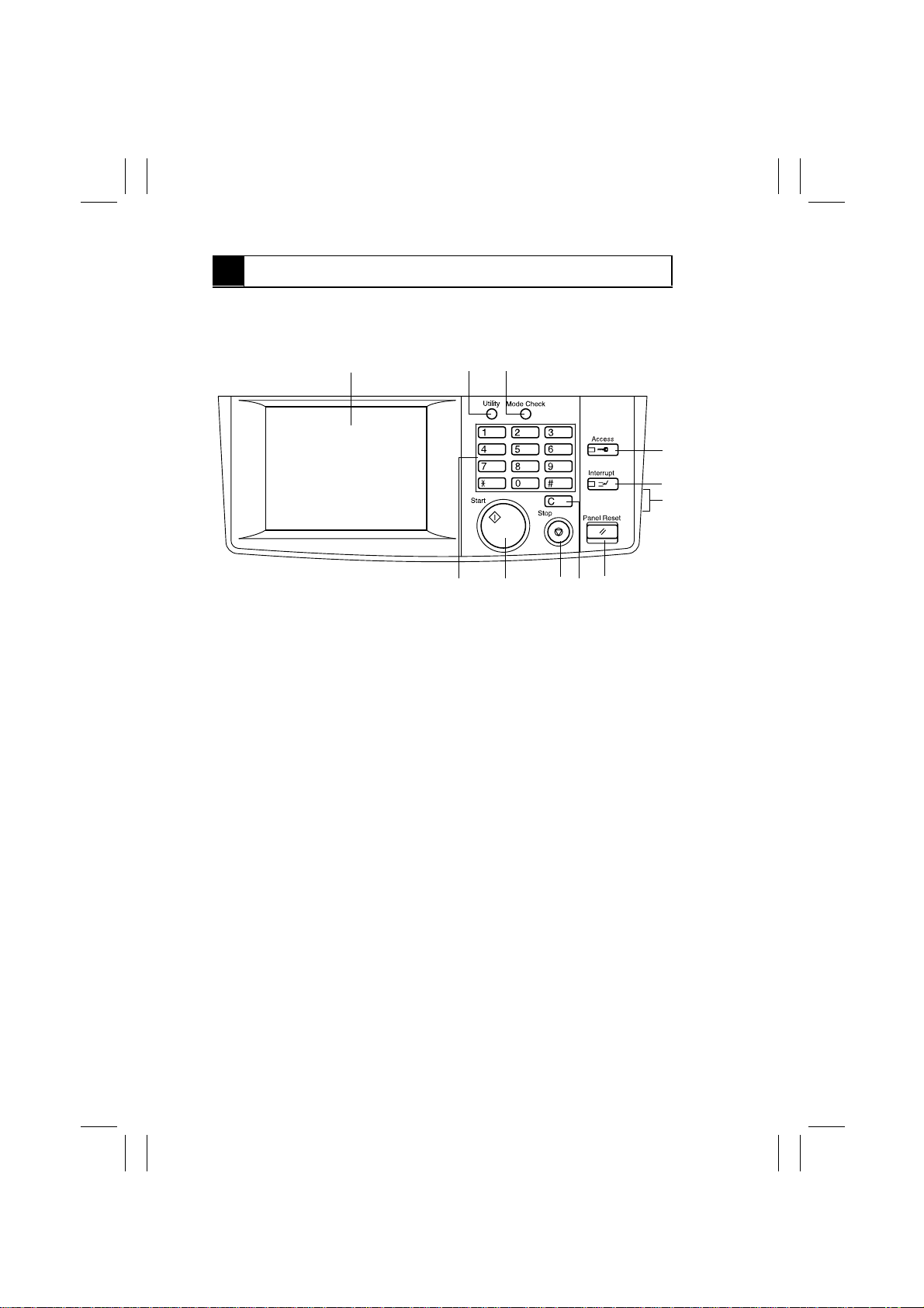
2-1.
Control Panel Keys
321
4
5
6
1. Touch Panel
•
Shows various screens and messages.
2. Utility Key
•
Press to show the User Mode menu.
3. Mode Check Key
•
Shows the Mode Check screen on which
the user can check the current copying
settings.
4. Access Mode Key
•
Used to enter the access number. After
the access number has been entered,
pressing this key will allow the user to
make copies.
5. Interrupt Key
•
Sets the copier into, or lets it leave, the
Interrupt mo de.
6. Display Contrast Knob
•
Turn to vary the brightness of the Touch
Panel.
7891011
7. Panel Reset Key
•
Clears all settings made on the control
panel, setting the copier back into the initial mode.
•
Cancels currently reserved jobs.
✽
It does not clear the zoom ratios and job
settings stored in memory and Interrupt
mode.
8. Clear Key
•
Clears the number-of-copies setting,
zoom ratio, and counter count.
•
Cancels the image data read.
9. Stop Key
•
Press to stop a scanning cycle.
•
Press to stop a print cycle.
10. Start Key
•
Press to start the document scanning
sequence.
•
Press to start a print cycle.
11. 10-key Pad
•
Numeric key pad used for entering the
number of copies to be made, zoom ratio,
access number, and the Tech. Rep. mode
settings.
1166O238EB
S-2
Page 6
FrameMaker Ver.5.5(PC) Di350 SWITCHES ON PWBs/TECH. REP. SE TTINGS
98.11.25
2-2. Explanation of the Touch Panel
(1) Basic Screen
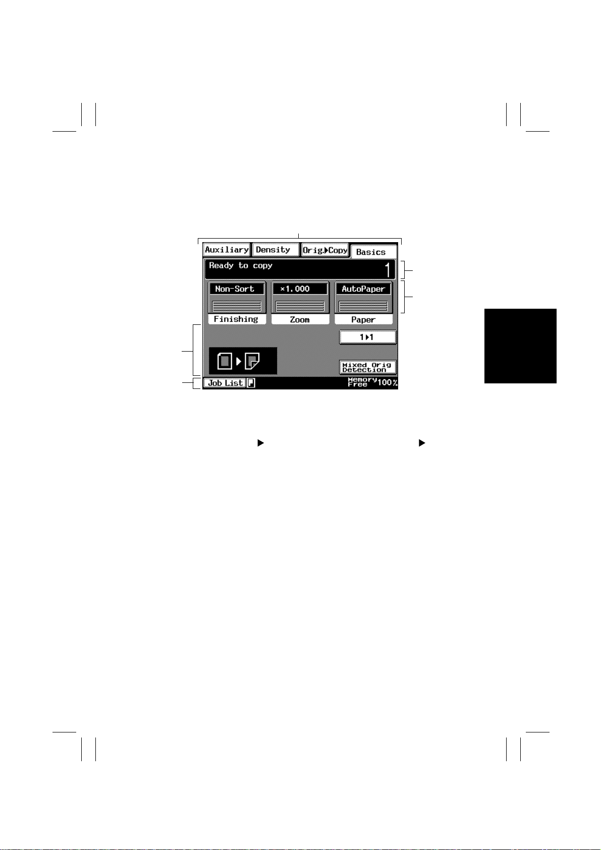
•
The Basic screen is the initial screen that appears when the copier panel is reset or auto
reset is activated.
1
2
3
4
5
1. Supplementary Function Key
•
Selects the corresponding menu screen,
either Auxiliary, Density, Orig.
Basics.
2. Message Display
•
Shows the current copier status, operating instructions, caution/warning messages, and other data including the
number of copies selected.
3. Basic Function Keys
•
Allows the user to select the finishing,
zoom ratio, and copy paper.
Copy, or
1168P169CC
4. Function Display
•
Shows graphic representations of the settings currently made for Orig.
and Finishing.
5. Status Display
•
Shows what is being done with the current
job and other data.
Copy
S-3
Page 7
FrameMaker Ver.5.5(PC) Di350 SWITCHES ON PWBs/TECH. REP. SE TTINGS
98.11.25
(2) Warning Screens
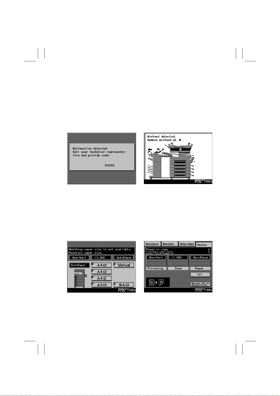
•
The warning screen may be a malfunction display, error display, warning display, or a
caution display.
<Malfunction Display>
•
A malfunction display is given when trouble occurs which cannot be corrected by
the user.
Example: Malfunctions that can be identi-
fied with a specific code.
<Warning Display>
•
A warning display is given when any further copier operation will not be possible,
or only a defective cop y will be produced,
because of erroneous or illegal panel settings or other cause.
Example: Unmatched paper size in Auto
Paper.
<Error Display>
•
An error display is given when trouble
occurs which can be corrected by the
user.
Example: P aper misf eed, toner empty, door
open.
1168P167CD1171S001CB
<Caution Display>
•
A caution display is given when, though
further copier operation will be possible, it
could result in a malfunction.
Example: Install new Imaging Cartridge.
S-4
1171S003CB1171S002CC
Page 8
FrameMaker Ver.5.5(PC) Di350 SWITCHES ON PWBs/TECH. REP. SE TTINGS
98.11.25
3
FUNCTION OF SWITCHES AND OTHER PARTS ON PWBs
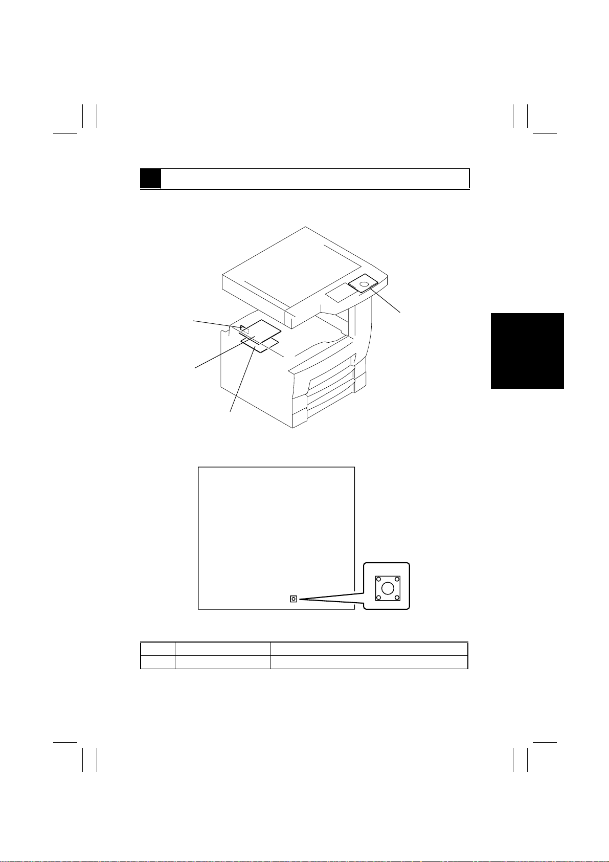
3-1. PWB Location
PWB-L
UN2
PWB-A
3-2. PWB-A (Master Board)
UN1
1171S004AA
S1
1167S002AA
1167S002AA
Symbol Name Description
S1 Test Print Switch Used to run a test print cycle.
S-5
Page 9
FrameMaker Ver.5.5(PC) Di350 SWITCHES ON PWBs/TECH. REP. SE TTINGS
98.11.25
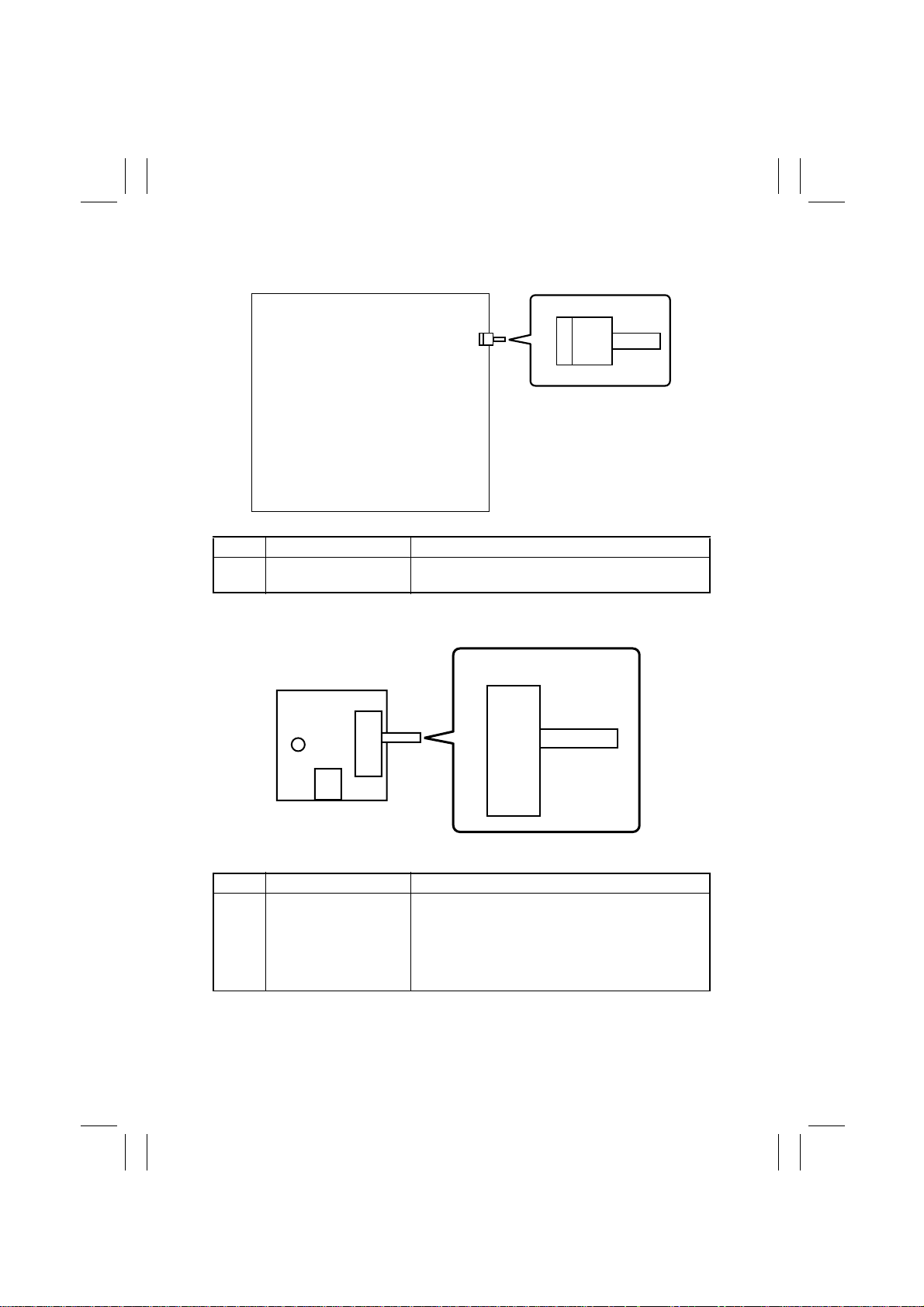
3-3. UN1 (Control Panel)
SW37
1167S018AA
1167S018AA
Symbol Name Description
SW37 Warm Restart Switch
•
Used to enter the initial mode.
•
Used to restart the copier after a breakdown.
3-4. PWB-L (PPM Switching Board)
SW1
H L
SW1
Symbol Name Description
S1 Low-Speed Mode
Selecting Switch
Used to make longer the paper-to-paper intervals as
a means of preventing the problem in which sheets of
paper are fed out untidily when large size paper left to
stand under high humidity condition is being used.
✽
Keep this switch in the H position, as it is only for
special users.
1167S026AB
1167S026AB
S-6
Page 10
FrameMaker Ver.5.5(PC) Di350 SWITCHES ON PWBs/TECH. REP. SE TTINGS
98.11.25
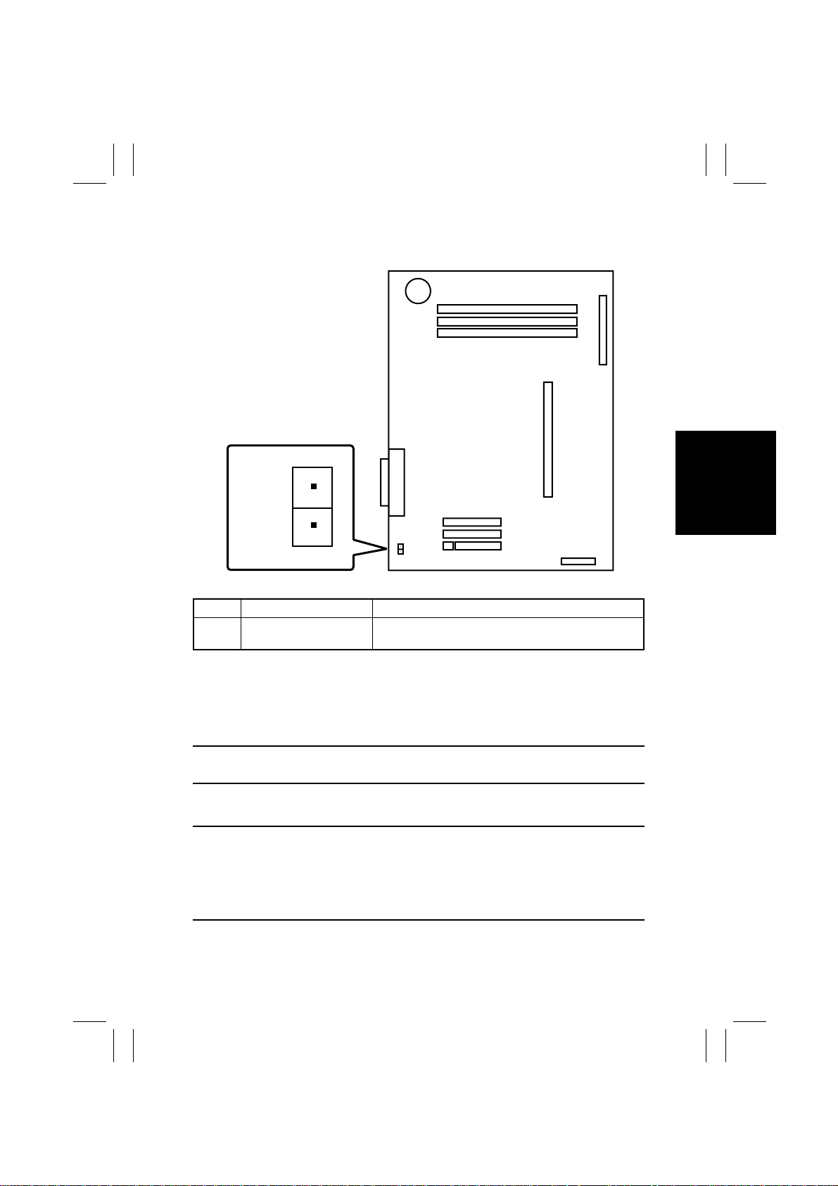
3-5. UN2 (MFB Board)
U6
U6
1167S027AA
Symbol Name Description
U6 Forced Memory Clear Used when it is not possible to clear RAM by warm
✽
Be careful about using these pins, as closing these pins clears all data including counter
data.
<Clearing Procedure>
1. Turn OFF the Power Switch.
2. Remove the Upper Cover and MFB Box Cover.
3. Close U6 and, in that condition, turn ON the Power Switch.
NOTE
Use care not to close any other circuit.
4. When the initial screen appears, turn the Power Switch OFF.
5. Open U6.
NOTE
When Forced RAM Clear has been performed, make these adjustments and settings once
again in this order:
1. “Marketing Area” of “Initial mode”
2. “Memory Clear” of “Initial mode”
3. Other adjustments and settings as necessary
restart.
S-7
Page 11
FrameMaker Ver.5.5(PC) Di350 SWITCHES ON PWBs/TECH. REP. SE TTINGS
98.11.25
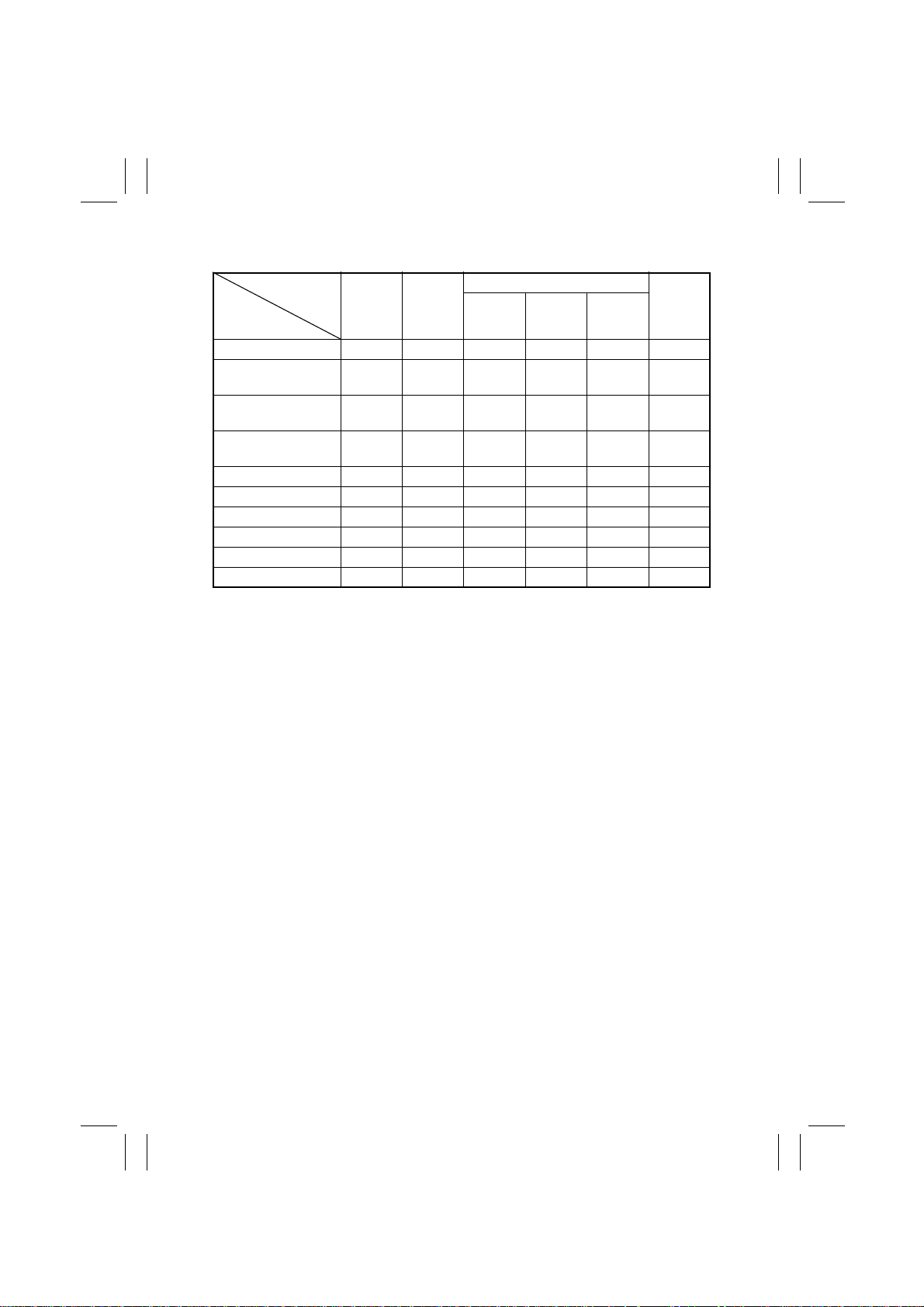
<Data/Conditions Cleared by Reset Switches/Pins>
Switches/Pins
Data/Conditions Cleared
Misfeed display
Malfunction display
(other than Fusing)
Malfunction display
(all including Fusing)
Erratic operation/
display
User’s Choice — —
Tech. Rep. Mode — —
Counter — — —
RD Mode — — —
Security Mode — —
Adjust Mode —————
❍
: Cleared (initialized) —: Not cleared
Power
Switch
OFF/ON
❍❍❍
❍❍❍
——
——
Side
Cover
open/
close
Memory
Clear
❍
❍
❍
❍
❍
Initial Mode
Total
Clear
—
——
—
—
——
——
❍
❍
——
Trouble
Reset
❍❍
❍❍
❍❍
—
—
Forced
RAM
Clear
❍
❍
❍
❍
❍
❍
❍
S-8
Page 12
FrameMaker Ver.5.5(PC) Di350 SWITCHES ON PWBs/TECH. REP. SE TTINGS
98.11.25
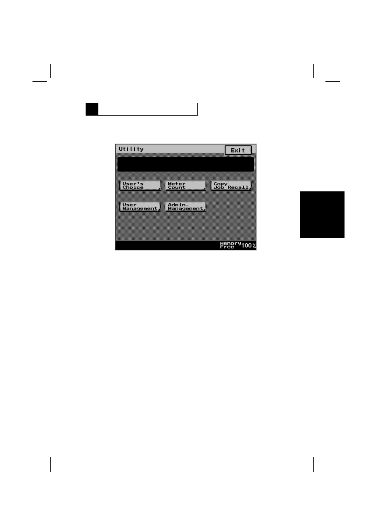
4 USER’S CHOICE MODE
•
The User’s Choice mode is used to make various settings according to the user’s needs.
4-1. User’s Choice Selection Screen
1167S009CB
4-2. User’s Choice Function Setting Procedure
<Setting Procedure>
1. Press the Utility key on the control panel and then touch the “User’s Choice” key.
2. Select the page number key that contains the desired function from among 1/5 through
5/5 shown at the bottom of the Touch Panel.
3. Select the function to be set and make settings as required.
4. After the settings are complete, touch the “Enter” key to validate the settings.
✽
The function selected is highlighted.
<Exiting the Mode>
•
Touch [Exit] on the screen to go back to the Basic screen.
S-9
Page 13
FrameMaker Ver.5.5(PC) Di350 SWITCHES ON PWBs/TECH. REP. SE TTINGS
98.11.25
4-3. User’s Choice Function Tree
Memory Recall
User’s Choice
1/5
2/5
3/5
Mixed Original Detection
Language Selected
Original
Auto Paper / Auto Size
Tray Priority
Special Pap er
2 • 4 in 1, Booklet
Copy Zoom
Auto Panel Reset
Energy Save Mode
Plug-In Counter,
ID Key Reset
Auto Shutt Off
LCD Back-light Off
4 in 1 Copy Order
Copy Default
4/5
5/5
S-10
Density Priority
Default Level (Copy)
Print Exposure
Output Priority
Intelligent Sorting
Output Tray
Small ID Original
Scanner Dry
Page 14
FrameMaker Ver.5.5(PC) Di350 SWITCHES ON PWBs/TECH. REP. SE TTINGS
Highlighted
ENGLISH
98.11.25
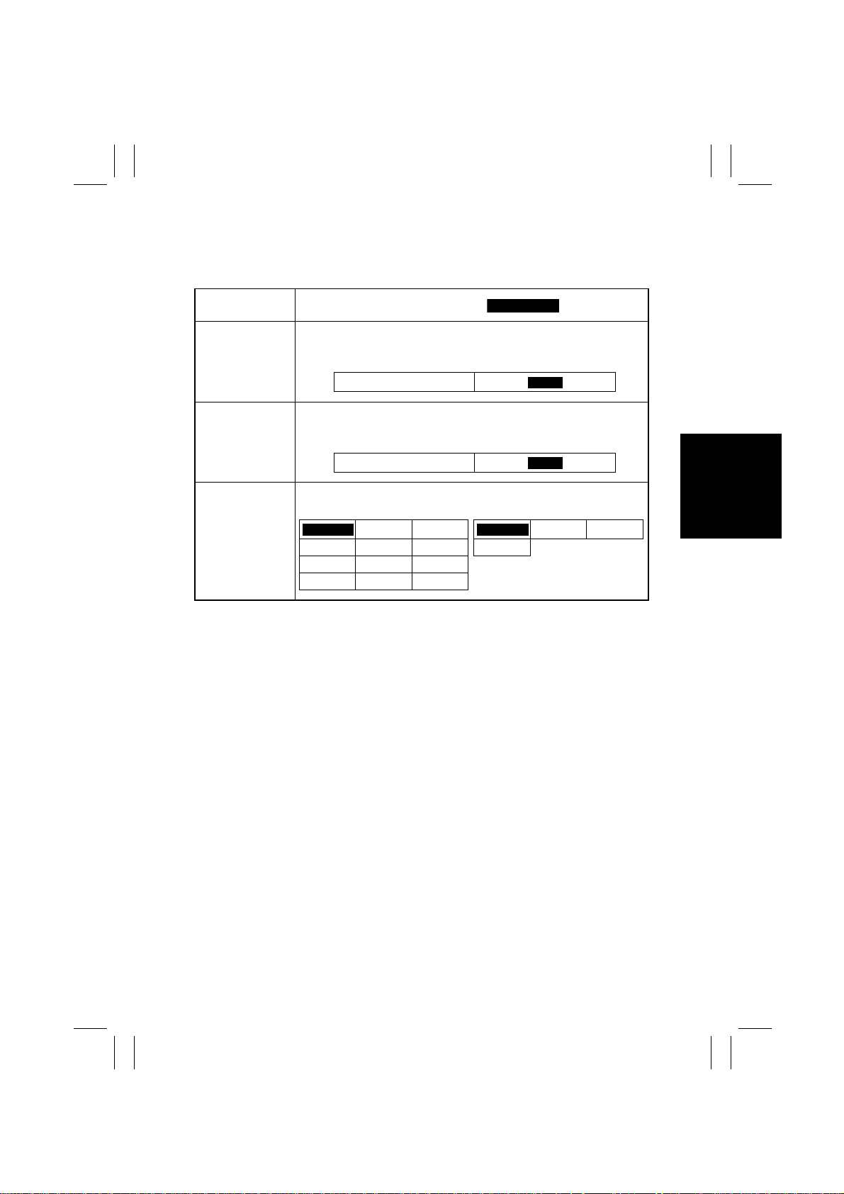
4-4. Settings in the User’s Choice Mode
1/5
Touch Panel
Display
Memory Recall Select whether to enable (“ON”) or disable (“OFF”) the function that
Mixed Original
Detection
Language
Selected
retains the image data even after the last copy paper has been fed
out, allowing the user to recall the same image data.
Select whether to let the system select by default (“ON”) the Mixed
Original Detection mode or not (“OFF”) when power is turned ON or
the Panel Reset key pressed.
Select the language of the Touch Panel messages.
ENGLISH
DUTCH ITALIAN SPANISH JAPA NESE
PORTUGUESE
SWEDISH FINISH JAPANESE
Setting (The default is ).
ON
ON
<Metric Areas> <Inch Areas>
GERMAN FRENCH FRENCH SPANISH
DANISH
NORWEGIAN
OFF
OFF
S-11
Page 15
FrameMaker Ver.5.5(PC) Di350 SWITCHES ON PWBs/TECH. REP. SE TTINGS
Highlighted
98.11.25
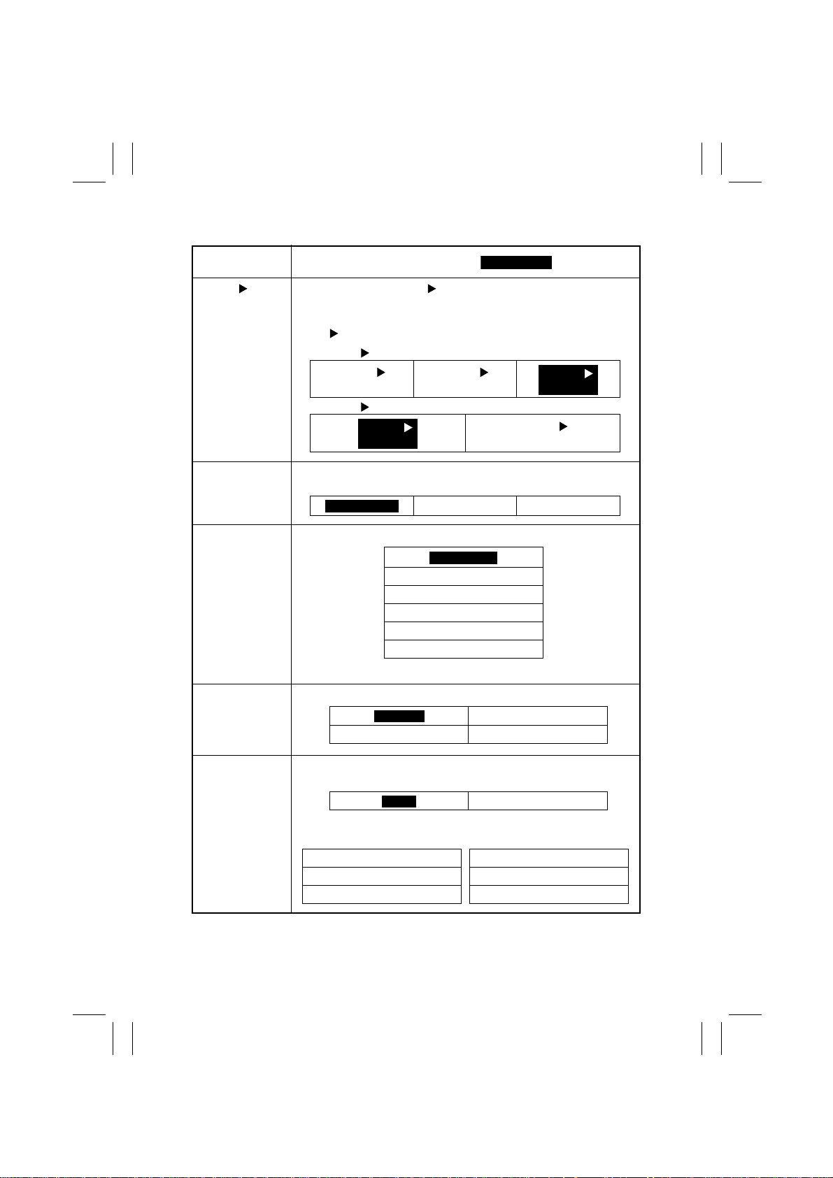
2/5
Touch Panel
Display
Original Copy
Default
Auto Paper/
Auto Size
Tray Priority Specify the paper source selected automatically.
Select the type of Original Copy setting selected automatically
when the copier is turned ON or Panel Reset key pressed. If “Duplex
only” is selected for “Simplex/Duplex” of the “Tech. Rep. Choice” function, 1 1 is not displayed.
<1-Sided 2-Sided>
<1-Sided 2-Sided>
Specify the default mode selected automatically when power is turned
ON or the Panel Reset key pressed.
Setting (The default is ).
1-Sided
2-Sided
1-Sided
2-Sided
Auto Paper
2-Sided
2-Sided
Auto Size Manual
1st Drawer
2nd Drawer
3rd Drawer
4th Drawer
5th Drawer
LCT
2-Sided
2-Sided
1-Sided
1-Sided
✽
Manual Bypass Tray is not selectable.
Special Paper Set up a drawer for special paper loading.
Normal
Recycled Special
2 • 4 in 1, Booklet
Copy Zoom
Select whether to enable (“ON”) or disable (“OFF”) recalling a default
zoom ratio for 2in1, 4in1, or Booklet Creation.
ON
The default zoom ratios are as follows when “ON” has been selected.
< Metric Areas >
× 0.500 4in1
× 0.707 2in1/Booklet
× 1.414 Separation
< Inch Areas >
× 0.500 4in1
× 0.647 2in1/Booklet
× 1.545 Separation
S-12
Not for 2-Sided
OFF
Page 16
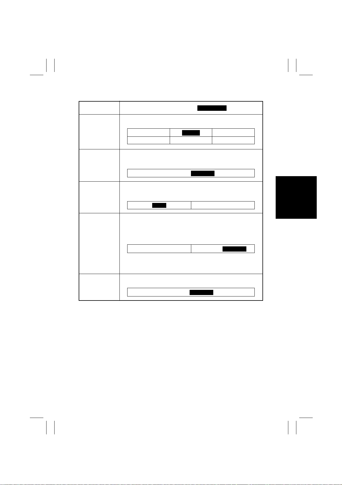
FrameMaker Ver.5.5(PC) Di350 SWITCHES ON PWBs/TECH. REP. SE TTINGS
Highlighted
(15 min)
(1 min)
98.11.25
3/5
Touch Panel
Display
Auto Panel Reset Specify the default ex posure mode selected automatically when
Energy Save Mode Set the time it tak es the copier to enter the Energy Sav er mode after a
Plug-In Counter,
ID key Reset
Auto Shut Off Select whether to turn ON or OFF the Auto Shut Off function that
LCD Back-light Off Set the time it takes the LCD backlight to turn OFF after a copy cycle
power is turned ON or the Panel Reset key pressed.
copy cycle has been completed or the last key operated. Use the 10key Pad to set the time (15 to 240 min.).
Select whether to reset (“ON”) the panel or not (“OFF”) automatically
when the Access Mode key is pressed or the Key Counter is
unplugged.
shuts down the copier a given period of time after a copy cycle has
been completed or the last key operated. Selecting “ON” means setting the time it takes the Auto Shut Off function to be activated, that
can range from 15 min. to 240 min.
✽
The option of “No Reset” becomes available on the screen if “Yes”
is selected for “Disable Sleep” of Utility - Admin. Management Administrator Set.
has been completed or the last key has been operated.
Setting (The default is ).
30 seconds 2 min
3 min 5 min No Reset
(15 to 240)
ON
No Reset
(1 to 240)
1 min
OFF
(15 to 240)
(60 min)
S-13
Page 17
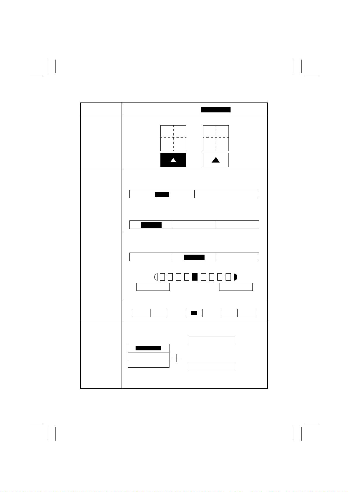
FrameMaker Ver.5.5(PC) Di350 SWITCHES ON PWBs/TECH. REP. SE TTINGS
Highlighted
98.11.25
4/5
Touch Panel
Display
4 in 1 Copy Order Specify the default copying order in the 4in1 mode.
Density Priority Specify the default exposure mode selected automatically when
Default Lev el
(Copy)
power is turned ON or the panel Reset key pressed.
<Density>
✽
“Photo” of “Original Image Type” cannot be selected when “Auto” is
selected.
<Original Image Type>
Auto: Select the default exposure level in the Aut o Exposure mode.
Manual: Set the default exposure level in the Manual Exposure mode.
Setting (The default is ).
21
34
Auto
Text
Lighter Darker
Photo Text/Photo
<Auto>
Normal
<Manual>
31
24
Manual
Lighter
✽
EXP. 1 (Lighter) to EXP. 9 (Darker)
Print Exposure Set the image density level for printing.
-2 -1 1 2
Output Priority Select the default finishing type when the copier is equipped with a
Sorter or Staple Sorter.
Non-Sort
Sort
Group
0
Staple
✽
Staple can be combined with either
Sort or Group.
Hole Punch
✽
Hole Punch can be combined with
any one of the functions.
Darker
S-14
Page 18
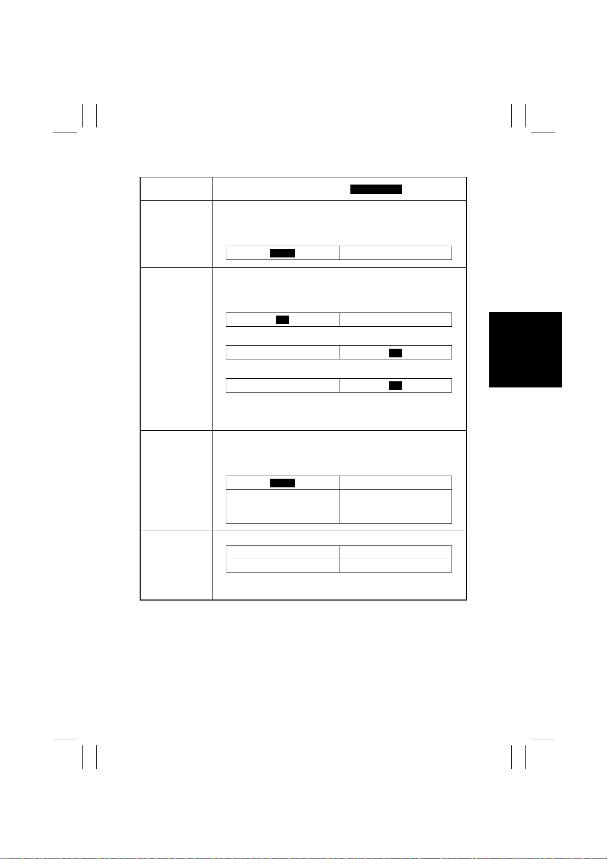
FrameMaker Ver.5.5(PC) Di350 SWITCHES ON PWBs/TECH. REP. SE TTINGS
Highlighted
98.11.25
5/5
Touch Panel
Display
Intelligent Sorting When the system is equipped with a finishing option and the ADF is
Output Tray Select the output tray for each application when the system is
Small ID Original Select whether to enab le (“ON”) a cop y cycle or not (“OFF”) when it is
being used, select whether to turn “ON” or “OFF” the function that
automatically switches between Sort and Non-Sort according to the
number of originals loaded in the ADF.
equipped with a Job Tray or Finisher.
<Printer>
•
Job Tray
•
Finisher
<Copier>
✽
1: 1st tray; 2: 2nd tray
✽
When the system is equipped with a Finisher, the option of “Copier”
and the tray designation keys “1” and “2” are not displayed.
initiated with no original placed on the Original Glass or with an original of a small size that is not detectable by the system (smaller than
A5) placed on the Original Glass.
The copy cycle is run using
the paper loaded in the
default paper source.
Setting (The default is ).
ON
1
1
1
ON
A warning message is given
and the copier inhibits the
start of this copy cycle.
OFF
2
2
2
OFF
Scanner Dry Set the time-of-day to run a Scanner drying cycle.
Hours Minutes
00 ~ 23 00 ~ 59
✽
When entering a value for Hours and Minutes and if it is a one-digit
number, first enter a “0.”
S-15
Page 19
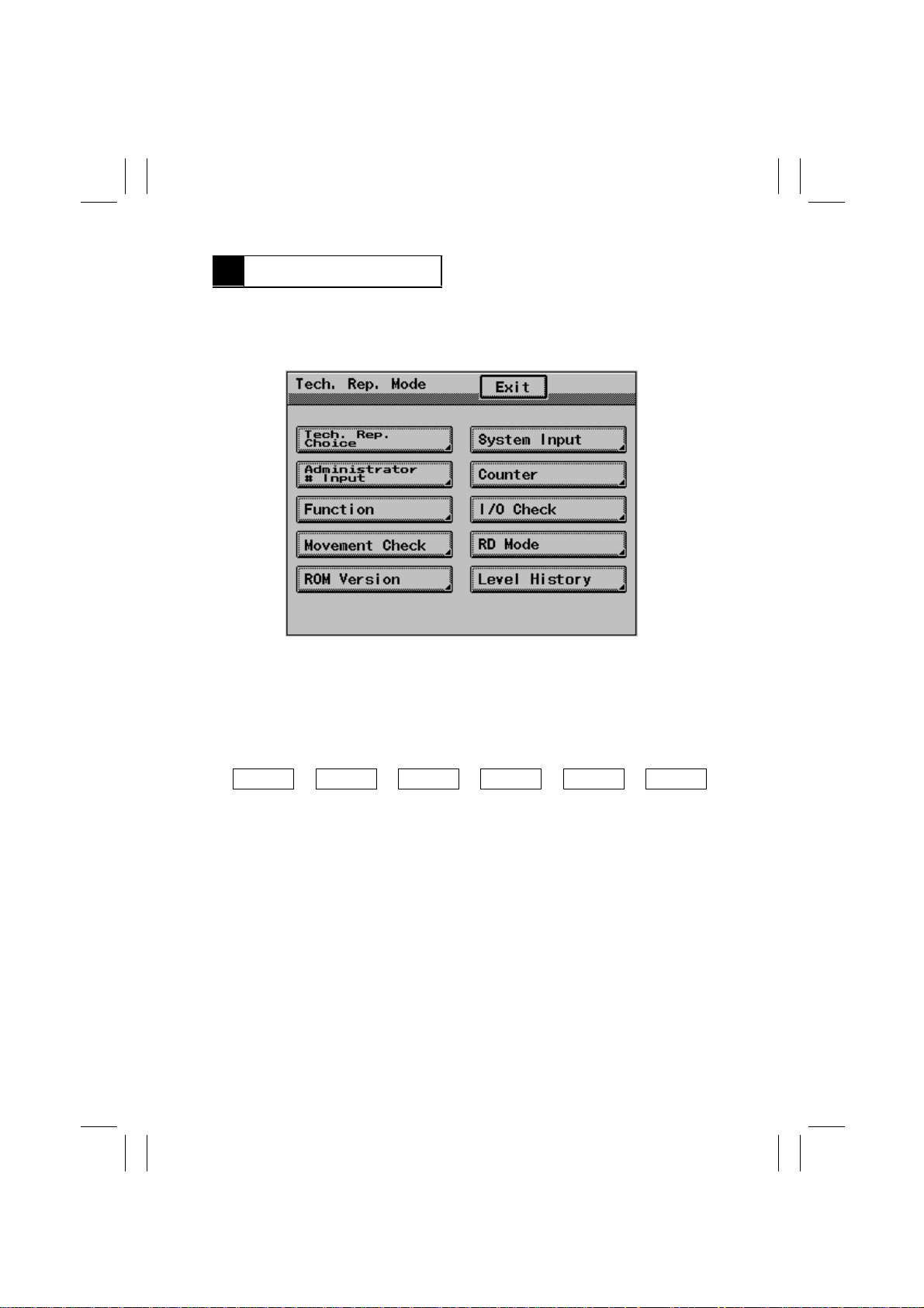
FrameMaker Ver.5.5(PC) Di350 SWITCHES ON PWBs/TECH. REP. SE TTINGS
98.11.25
5 TECH. REP. MODE
•
This mode is used by the Tech. Rep. to set, check, adjust, and/or program various service functions.
5-1. Tech. Rep. Mode Menu Screen
1171S005CA
5-2. Tech. Rep. Mode Function Setting Procedure
<Setting Procedure>
1. Set the copier into the Tech. Rep. mode by the following method:
•
With the “Meter Count” screen opened from the Utility menu screen, press the following
keys in this order:
Stop Key
2. Select the particular Tech. Rep. mode function to be set.
3. Make the necessary settings according to the function selected.
✽
The function selected is highlighted.
<Exiting the Mode>
•
Touch [Exit] on the screen to go back to the Basic screen.
➡
➡
0
➡
0
Stop Key
➡
➡
0
1
S-16
Page 20
FrameMaker Ver.5.5(PC) Di350 SWITCHES ON PWBs/TECH. REP. SE TTINGS
98.11.25
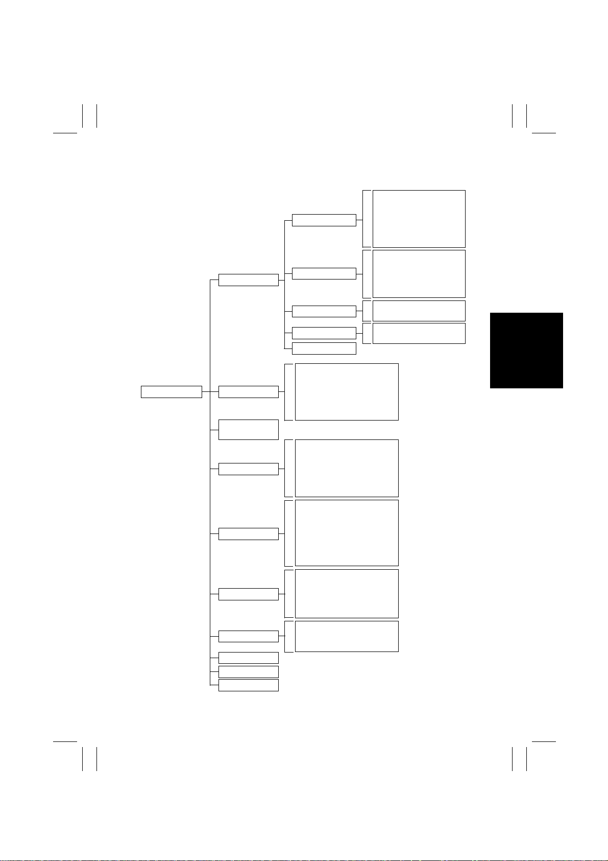
5-3. Tech. Rep. Mode Setting Tree
Auto Paper Configuration
FLS Paper
Simplex/Duplex
Dry Key Set
Function Limit
Special Image Quality
Edge Erase
Loop Adjustment
Image Density
ATDC Sensor Gain
VG Adjust
Original Stop Position
Registration Loop
Registration
Zoom Adjust
Tech. Rep. Mode
Tech. Rep. Choice
System Input
Administrator #
Input
Counter
Function
I/O Check
Movement Check
RD Mode
Rom Version
Level History
System Set
Printer
ADFR
Scan-through ADF
IR-Erasure Width
Paper Size Input
Change Fixed Zoom
Machine Configuration
Technical Memo
Permit Imaging Cartridge
Original Size Detecting Option
Paper
Jam
PM
Trouble
Device
Maintenance
F1 : Pap er Passage
F2: HV Output Setting
F7-1: Original Size Detecting
Sensor Adjustment
F8: ATDC Sensor Automatic
Adjustment
F12: Test Pattern
Scan-through ADF
Scanner
ADFR
Output Option
Printer
ADF Paper Passage
Scanner
Exp. Lamp Check
S-17
Page 21
FrameMaker Ver.5.5(PC) Di350 SWITCHES ON PWBs/TECH. REP. SE TTINGS
Highlighted
98.11.25
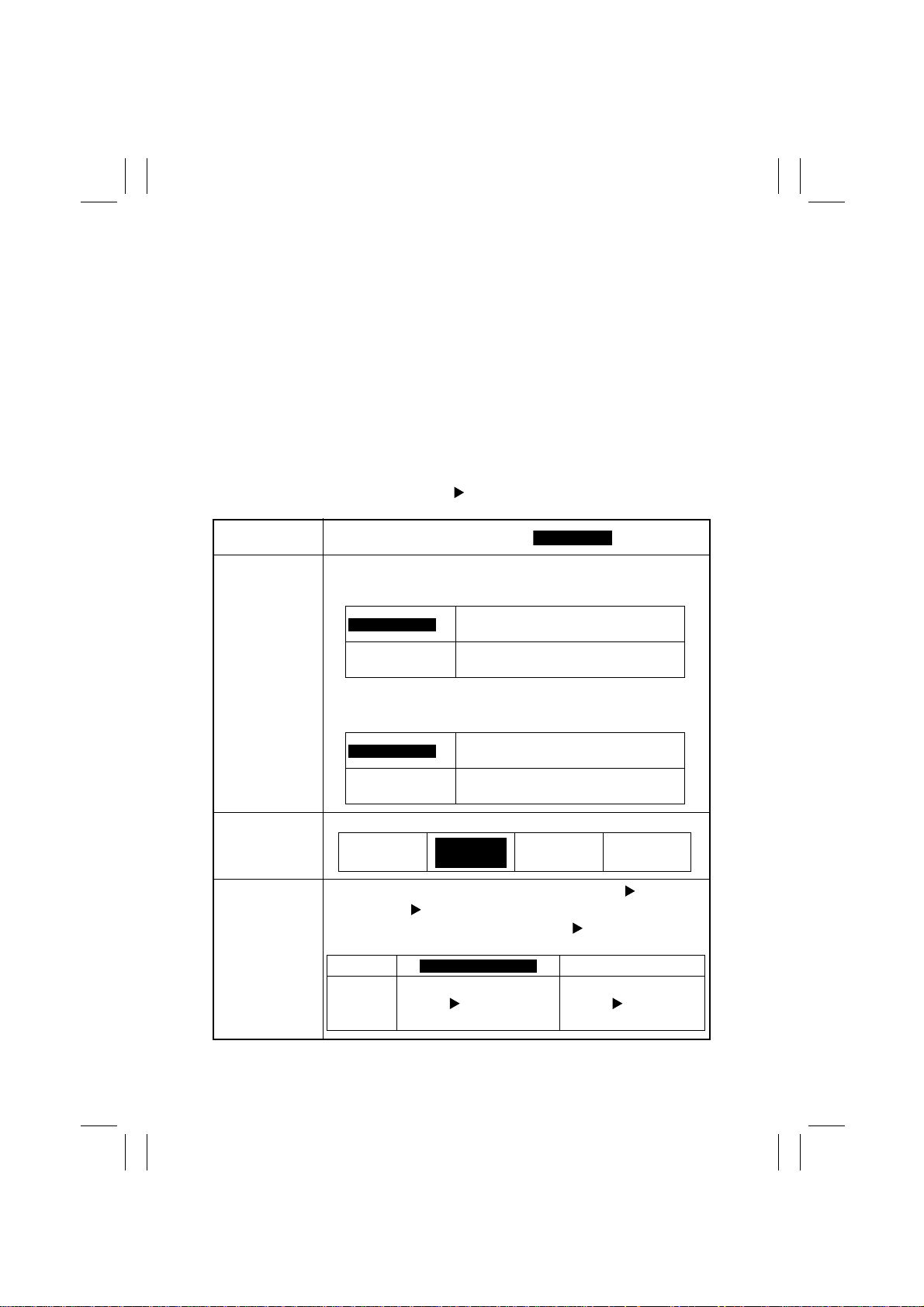
5-4. Settings in the Tech. Rep. Mode
(1) Tech. Rep. Choice
•
This function allows the Tech. Rep. to make the various settings and adjustments.
<Function>
1. System Set
2. Printer
3. ADFR
4. Scan-through ADF
<Setting Procedure>
1. Touc h [Tech. Rep. Choice] to open a screen to Tech. Rep. Choice.
2. Touch the desired major category key.
3. Touch the desired sub-category key.
Tech. Rep. Mode Tec h. Rep. Choice
<System Set>
Touch Panel
Display
Auto Paper Configuration
<Metric Areas>
Select either “Inch/Metric” or “Metric” for rounding off the original size
detected.
Inch / Metric
Metric
<Inch Areas>
Select either “Inch/Metric” or “Inch” for rounding off the original size
detected.
Inch / Metric
Inch
Setting (The default is ).
The measurement is rounded to the
nearest standard inch or metric size.
The measurement is rounded to the
nearest standard metric size.
The measurement is rounded to the
nearest standard inch or metric size.
The measurement is rounded to the
nearest standard inch size.
FLS Paper Set the size for FLS.
F: 330 mm
C: 203 mm
Simplex/Duplex
Select whether or not to enable the setting of 1-Sided 1-Sided
under Original Copy Default available from User’s Choice.
✽
If “Simplex & Duplex” is selected, 1-Sided 1-Sided becomes
available as an option.
Display Duplex Only
Description Does not limit the options f or
Simplex & Duplex
Original Copy Default to
2-sided copying only.
F: 330mm
C: 210mm
S-18
F: 330 mm
C: 216 mm
Limits the options for
Original Copy Default
to 2-sided copying only.
F: 330 mm
C: 220 mm
Page 22
FrameMaker Ver.5.5(PC) Di350 SWITCHES ON PWBs/TECH. REP. SE TTINGS
Highlighted
Highlighted
98.11.25
Tech. Rep. Mode Tec h. Rep. Choice
Touch Panel
Display
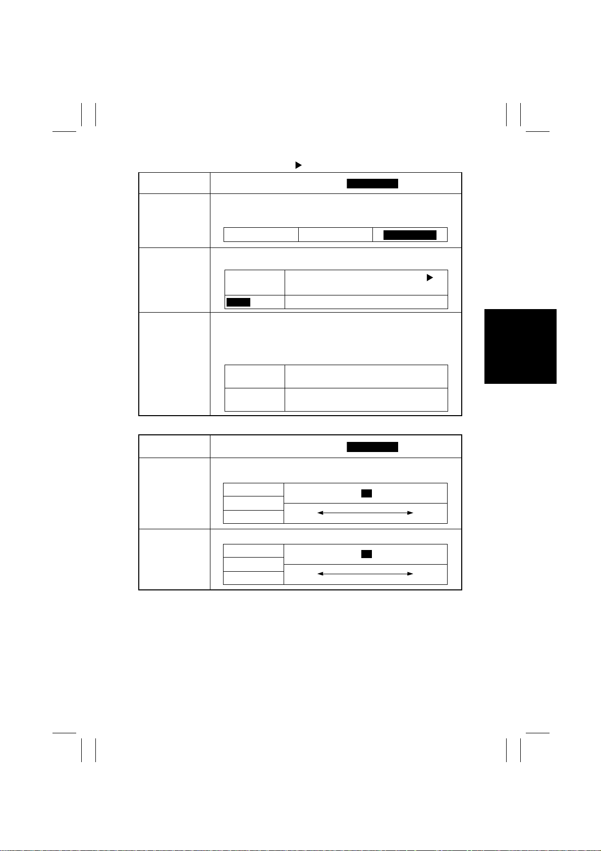
Dry Key Set Select whether to displa y the Dry key for “User Management” of Utility.
Function Limit Select whether to limit (“ON”) the functions to be set on the control
Special Image
Quality
If the key is to be display ed, select whether to dry only the Scanner or
both Scanner and Drum.
panel or not (“OFF”).
ON
OFF
Select whether to enable the selection of Special Image Quality for
“Density Priority” of User’s Choice (applicable on a case-by-case
basis).
✽
Touching the “✽” key on the System Set menu selects or cancels
this function.
✽
Key high-
lighted
✽
Key not high-
lighted
Setting (The default is ).
Scanner Scanner & Drum
Enables the functions other than Orig.
Copy and Auxiliary.
Enables all functions (no Limit).
The Special Image Quality key is displayed.
The Special Image Quality key is not displayed.
Disable
<Printer>
Touch Panel
Display
Edge Erase Set the erase width on the leading, trailing, right, and left edge of the
image.
Leading
Trailing
Right/Left
Loop Adjustment
Set the loop length to be formed before the Synchronizing Rollers.
1st Drawer
Other Drawers
Duplex & Manual
Setting (The default is ).
0mm......................... ...................... 5mm
Smaller Greater
-5mm........................ .................... +5mm
Smaller Greater
4
0
S-19
Page 23
FrameMaker Ver.5.5(PC) Di350 SWITCHES ON PWBs/TECH. REP. SE TTINGS
Highlighted
155
Highlighted
98.11.25
Tech. Rep. Mode Tec h. Rep. Choice
Touch Panel
Display
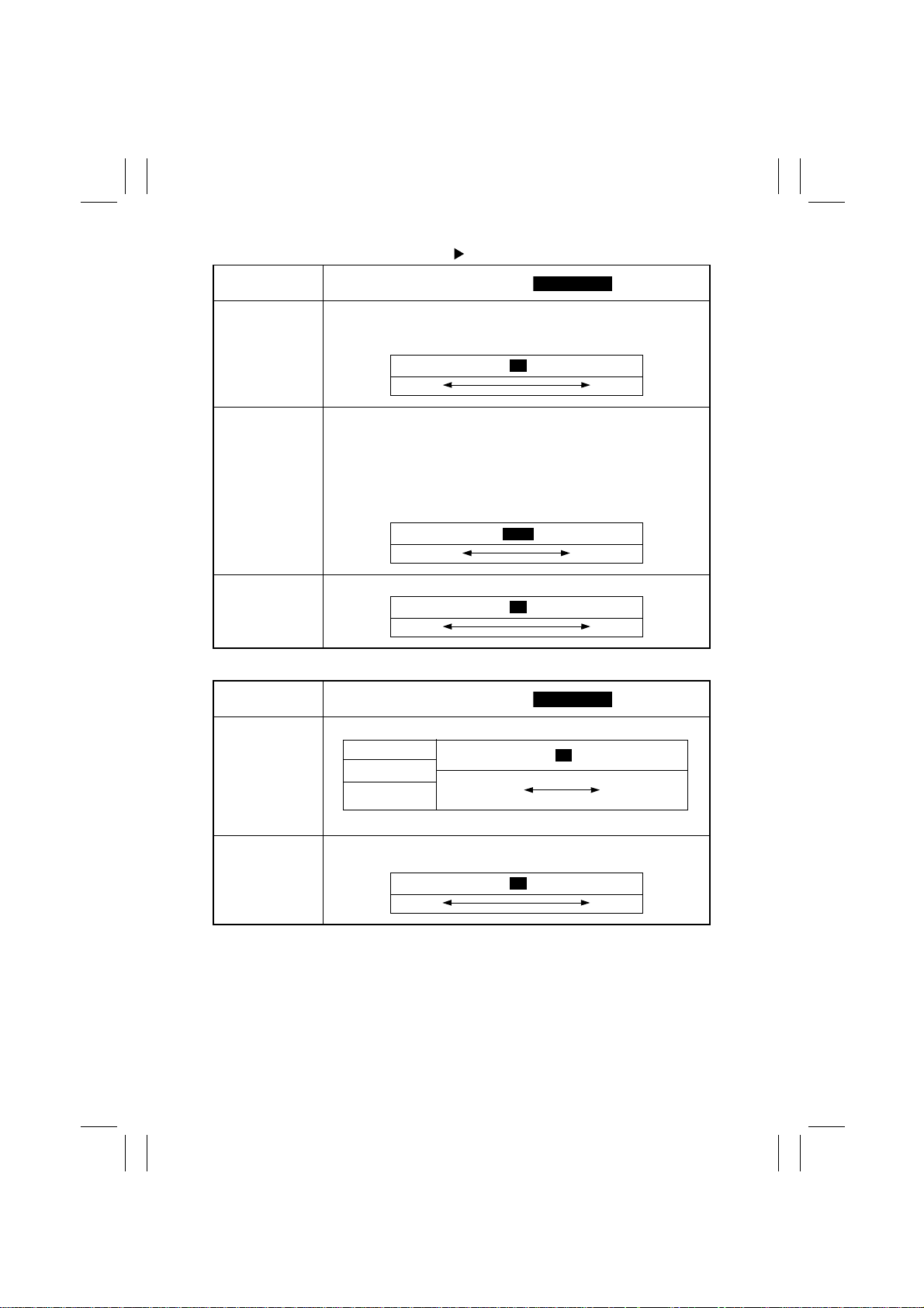
Image Density Set the image density for the printer.
✽
The value set for this function becomes the central value of “Print
Exposure” of User’s Choice.
Setting (The default is ).
-2.............................. ...........................+4
Lighter Darker
0
ATDC Sens or
Gain
VG Adjust Set VG when a fog or void occurs in the image.
<ADFR>
Touch Panel
Display
Original Stop
Position
Registration Loop Set the loop length to be formed in the original bef ore t he Registr ation
Current: Shows the current ATDC control voltage.
Set: Set the ATDC control voltage.
✽
If the “Set” value is to be changed, be sure to record the “Current”
value.
✽
The ATDC Sensor Gain value can be converted to a voltage value
using the following equation.
ATDC Sensor Gain = 5.1 × 2.2 × [setting value] ÷ 256 (V)
123......................... ......................186
T/C Greater T/C Smaller
-2.............................. ........................... +2
Lighter Darker
Setting (The default is ).
Set the document stop position in each of the ADFR modes.
1-Sided Set
2-Sided Set
Single Feed Set
✽
The minimum setting value is -6 only for 2-Sided Set.
Roller of ADFR.
-7.............................. ..........................+7
Original Width
Scale end
-5mm..................... ... ........... ..........+5mm
Smaller Greater
0
0
Original Glass
end
0
S-20
Page 24
FrameMaker Ver.5.5(PC) Di350 SWITCHES ON PWBs/TECH. REP. SE TTINGS
Highlighted
1.000
Highlighted
98.11.25
Tech. Rep. Mode Tec h. Rep. Choice
<Scan-through ADF>
Touch Panel
Display
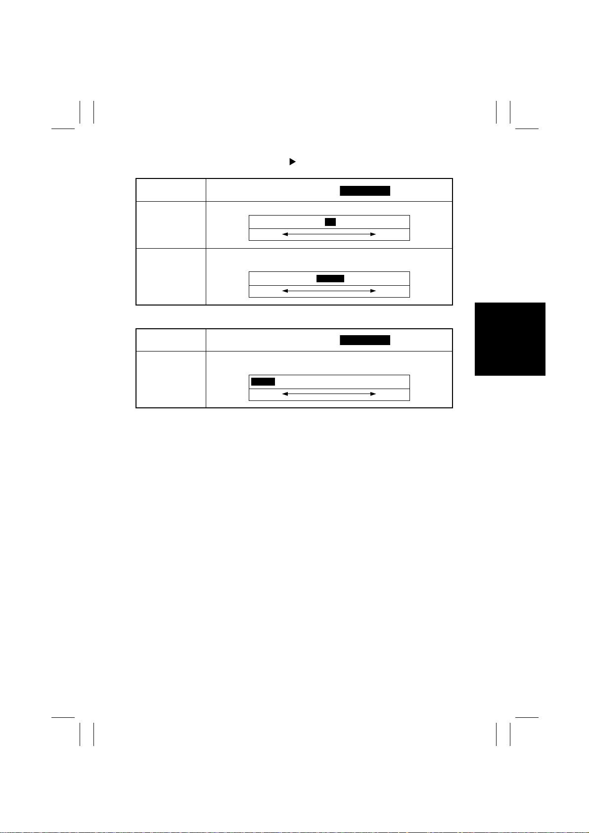
Registration Adjust registration in the main and sub scanning directions of the ADF.
Setting (The default is ).
-127 dot.................... .................+127 dot
Smaller Greater
0
Zoom Adjust Adjust the scanning zoom ratio in the main and sub scanning direc-
<IR-Erasure Width>
Touch Panel
Display
IR-Erasure Width Set the forced erasure width along the four edges of the paper to
tions of the ADF.
0.990.................... ..................1.010
Smaller Greater
Setting (The default is ).
erase shadows which are otherwise produced by the Original Scales.
...................................................3mm
0mm
Smaller Greater
S-21
Page 25
FrameMaker Ver.5.5(PC) Di350 SWITCHES ON PWBs/TECH. REP. SE TTINGS
98.11.25
(2) System Input
•
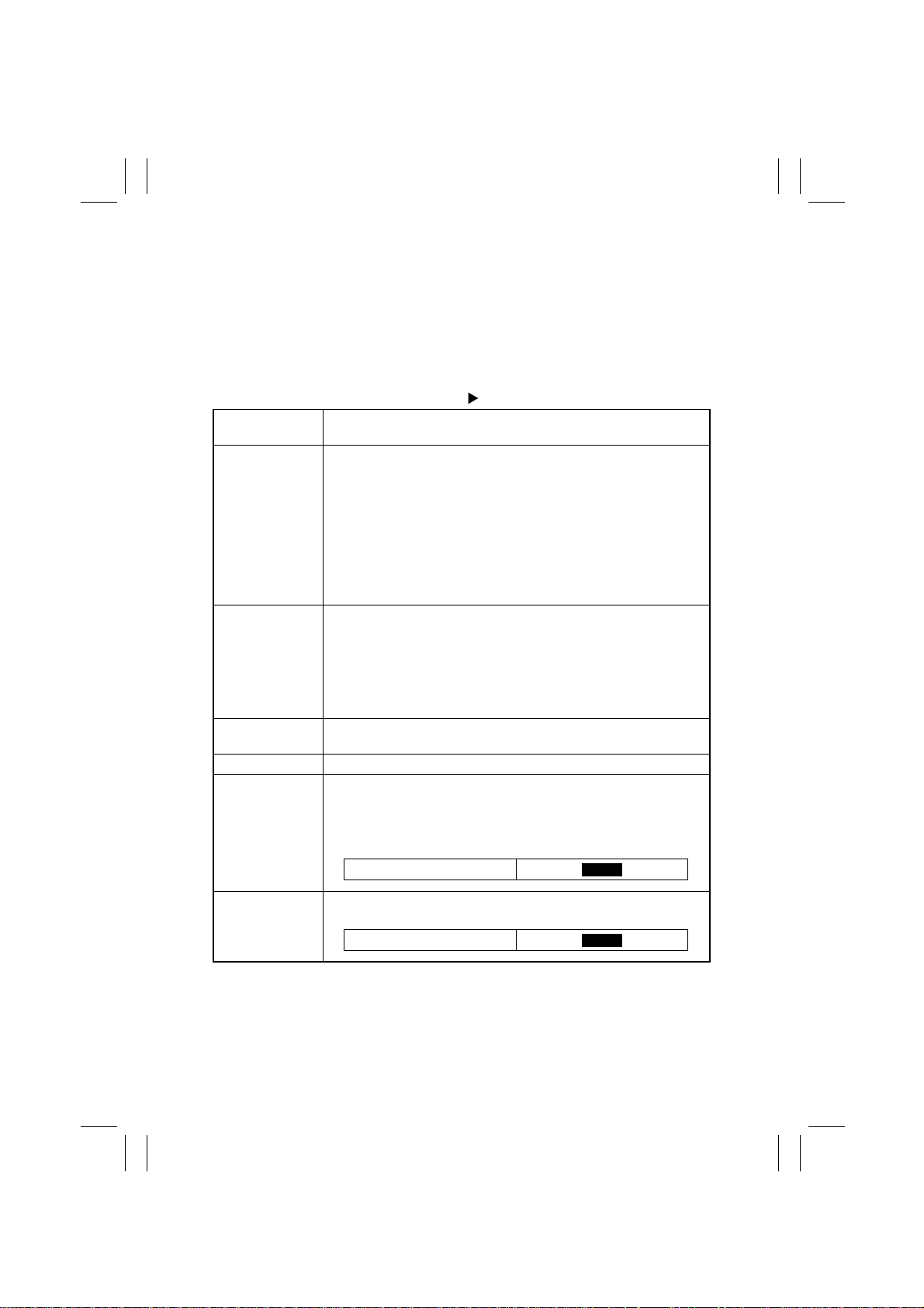
This function allows the Tech. Rep. to change the fixed zoom ratios, set the paper size,
define the marketing area, configure for the Key Counter, and input the telephone number.
<Setting Procedure>
1. Touch [System Input] to open the System Input menu screen.
2. Touch the desired subfunction key.
Tech. Rep. Mode System Input
Touch Panel
Display
Paper Size Input Set the size of the paper used in each paper source.
Change Fixed
Zoom
Machine Configuration
Technical Memo Enter the serial number and other data.
Permit Imaging
Cartridge
✽
This function cannot be used for the LCC as its paper is set with its
internal DIP switch.
<Procedure>
1. Touch the key of the paper source for which the paper size setting
is to be changed to show the Paper Size Input screen.
2. To uch the desired paper size key.
✽
If the 10-key Pad has been selected, enter the FD and CD size of
the paper from the 10-Key Pad.
3. To uch [END] to validate the paper size setting.
Change a fixed zoom ratio to a desired value in the range between
×0.250 and ×4.000.
<Procedure>
1. To uch the key of the fixed zoom ratio to be changed.
2. Press the Clear key to clear the setting and enter the new ratio
from the 10-Key Pad.
3. Touch [Input] to validate the new setting.
Displays the machine configuration status.
Select whether to permit the use of an illegal Imaging Cartridge
installed. The use is enabled when [Enter] is touched after “Yes” has
been selected.
✽
It is not possible to disable the use of an Imaging Cartridge once
permitted.
Yes
Operation
No
Original Size
Detecting Option
Set whether the optional Original Size Detecting Sensor is available
or not.
ON
OFF
S-22
Page 26
FrameMaker Ver.5.5(PC) Di350 SWITCHES ON PWBs/TECH. REP. SE TTINGS
98.11.25
(3) Administrator # Input
•
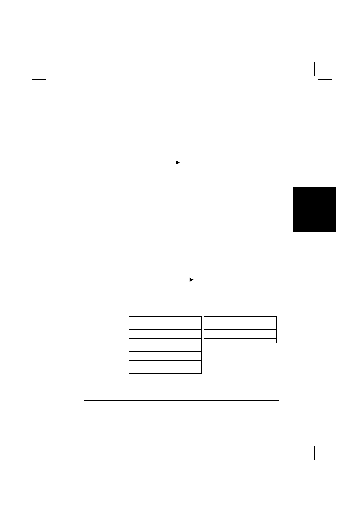
This function allows the Tech. Rep. to set the administrator number that is used to open
the “Admin. Management” screen of Utility.
<Setting Procedure>
1. Touch [Administrator # Input] to open the Administrator # Input menu screen.
2. Blank out the numeric data with the Clear key and enter the desired number from the
10-Key Pad.
3. Touch [Enter] to validate the entry of the number.
Tech. Rep. Mode Administrator # Input
Touch Panel
Display
Administrator #
Input
Set the administrator number used to open the “Admin. Management”
screen of Utility from the 10-Key Pad.
Operation
(1 to 8 digits: 0 to 99999999)
(4) Counter
•
This function maintains the counts of the various counters, thus aiding the Tech. Rep. in
performing service jobs.
<Setting Procedure>
1. Touch [Counter] to open the Counter menu screen.
2. Touch [Check] and then the desired counter to open the detailed counter screen.
3. To clear a count, touch [Counter Reset], the key of the counter to be cleared, and
[END].
✽
Two or more counters can be selected.
Tech. Rep. Mode Counter
Touch Panel
Display
Operation
Paper Shows the number of sheets of paper used by the size and type. Each
counter may be reset to 0 independently of the others:
<Paper Counter 1/2>
Display Description
A3 A3L
B4 B4L
A4 A4L/C
B5 B5L/C
A5 A5L/C
B6 B6L
A6 A6L
11 × 17 11” × 17”L
11 × 14 11” × 14”
Letter Letter L/C
Legal Legal L/C
5-1/2 × 8-1/2 5-1/2” × 8-1/2” L/C
<Paper Counter 2/2>
Display Description
FLS. FLS.
Normal Normal
Recycled Recycled
Special Special
Not for 2-Sided Not for 2-Sided
<Clearing a Count>
Touch the item key whose count is to be cleared and press the Clear
key. If a count is accidentally cleared, pressing the Interrupt key will
undo the clear operation.
S-23
Page 27
FrameMaker Ver.5.5(PC) Di350 SWITCHES ON PWBs/TECH. REP. SE TTINGS
98.11.25
Tech. Rep. Mode Counter
Touch Panel
Display
Operation
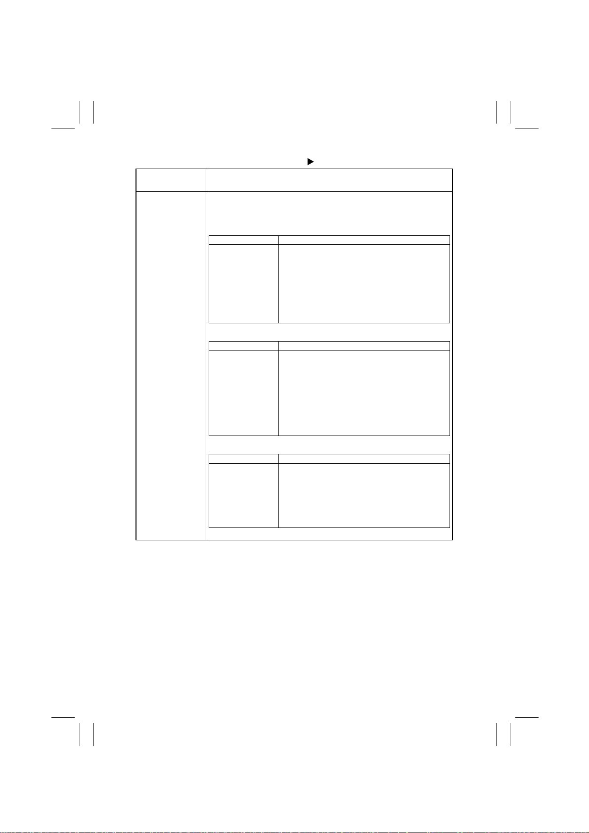
Jam Shows the number of misfeeds that have occurred in different parts of
the system, together with rates of occurrence (MCBJ, MDBJ). Each
counter may be reset to zero independently of the others:
<Jam Counter 1/5>
Display Description
MCBJ System
MCBJ Machine Only
1st Drawer
2nd Drawer
3rd Drawer
4th Drawer
5th Drawer
Average no. of copies made for each paper misfeed:
MCBJ Total Counter ÷ Jam Counter (including misfeeds in Finisher)
Average no. of copies made for each paper misfeed:
MCBJ Total Counter ÷ Jam Counter (excluding misfeeds in Finisher)
No. of misfeeds that occurred at the 1st Drawer of the copier
No. of misfeeds that occurred at the 2nd Drawer of the copier
No. of misfeeds that occurred at the 3rd Drawer of the copier
No. of misfeeds that occurred at the 4th Drawer of the copier
No. of misfeeds that occurred at the 5th Drawer of the copier
<Jam Counter 2/5>
Display Description
Manual Feed
Vertical Transport
Separator
Fusing
Duplex Entrance
Duplex Feed
LCC Feed
No. of misfeeds that occurred at the Manual Bypass Tray
No. of misfeeds that occurred at the paper take-up/transport
section of the copier
No. of misfeeds that occurred at the paper separator section of
the copier
No. of misfeeds that occurred at the Fusing Unit of the copier
No. of misfeeds that occurred at the turnover/storage section of
the copier
No. of misf eeds that occurred a t the pape r tak e-u p section of the
Duplex
No. of misf eeds that occurred a t the pape r tak e-u p section of the
LCC
<Jam Counter 3/5>
Display Description
LCC Transport
Shift/2Bin Tray Transport
Shift/2Bin Tray Exit
Finisher Horizontal
Transport
Finisher Transport
Finisher Exit
Finisher Staple
2Bin Tray = J o b Tr ay
✽
No. of misfeeds that occurred in the LCC transport section
No. of misf eeds t hat occ urre d in t he S hift/Jo b Tray transport section
No. of misfeeds that occurred in the Shift/Job Tray exit section
No. of misfeeds that occurred in the Finisher horizontal transpo rt
section
No. of misfeeds that occurred in the Finisher transport section
No. of misfeeds that occurred in the Finisher exit section
No. of Finisher staple misfeeds that occurred
S-24
Page 28
FrameMaker Ver.5.5(PC) Di350 SWITCHES ON PWBs/TECH. REP. SE TTINGS
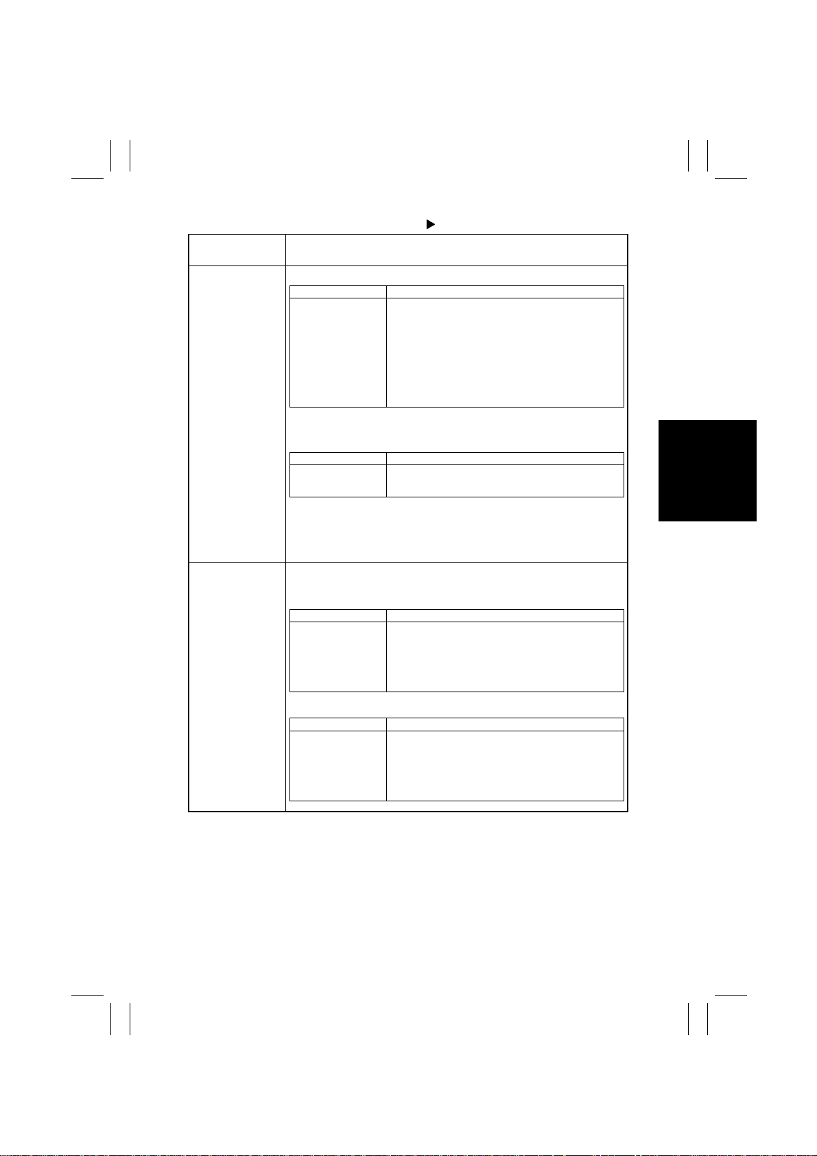
98.11.25
Tech. Rep. Mode Counter
Touch Panel
Display
Operation
Jam <Jam Counter 4/5>
Display Description
Finisher Set Transport
MDBJ
ADF (Scan-through
ADF) Feed
ADF (Scan-through
ADF) Transport
ADFR Reverse
SADF
No. of misfeeds that occurred in the Finisher Tray
Average no. of document transport sequences for each document misfeed:
ADFR Document Passage Counter ÷ ADFR Jam Counter
No. of misf eeds that occurred a t the pape r tak e-u p section of the
ADF (Scan-through ADF)
No. of misfeeds that occurred at the do cumen t tr ans port section
of the ADF (Scan-through ADF)
No. of misfee ds that occurred at the document turnov er and exit
sections of the ADFR
No. of misfeeds that occurred at the SADF
<Jam Counter 5/5>
Display Description
Printer
Engine
No. of misfeeds that occur red due to illegal desig nation of FC U2
No. of misfeeds that occurred due to communication error with
engine (VD fault)
<Clearing a Count>
Touch the item key whose count is to be cleared and press the Clear
key. If a count is accidentally cleared, pressing the Interrupt key will
undo the clear operation.
PM Shows the frequency of use of each of the PM parts. Each counter
may be reset to 0 independently of the others:
<PM Counter 1/3>
Display Description
I/C Life
Fusing Unit
1st Drawer
2nd Drawer
3rd Drawer
4th Drawer
5th Drawer
No. of revolutions of I/C
No. of times a sheet of paper is fed out
No. of sheets of paper fed from the 1st Drawer
No. of sheets of paper fed from the 2nd Drawer
No. of sheets of paper fed from the 3rd Drawer
No. of sheets of paper fed from the 4th Drawer
No. of sheets of paper fed from the 5th Drawer
<PM Counter 2/3>
Display Description
LCC Parts 1
LCC Parts 2
Other PM Parts 1
Other PM Parts 2
Other PM Parts 3
1-Sided
2-Sided
No. of sheets of paper fed from the LCC (for 200k)
No. of sheets of paper fed from the LCC (for 300k)
No. of print cycles run (for 100k)
No. of print cycles run (for 150k)
No. of print cycles run (for 60k/120k)
No. of times a 1-sided original is fed through
No. of times a 2-sided original is fed through
S-25
Page 29
FrameMaker Ver.5.5(PC) Di350 SWITCHES ON PWBs/TECH. REP. SE TTINGS
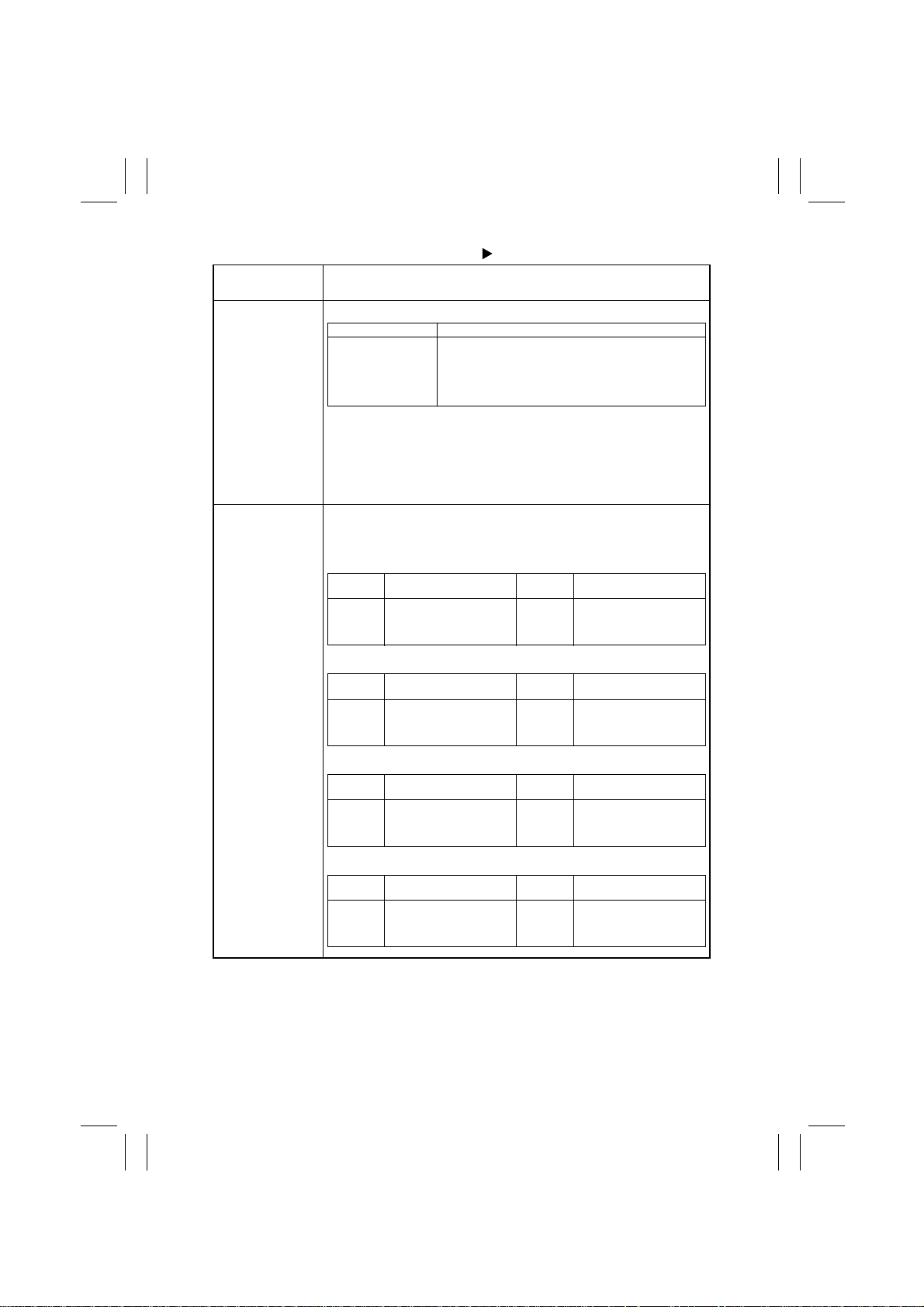
98.11.25
Tech. Rep. Mode Counter
Touch Panel
Display
Operation
PM <PM Counter 3/3>
Display Description
SADF
IR 1
IR 2
2 Bin Tray
Toner Pages
2Bin Tray = J o b Tr ay
✽
No. of single feeds
No. of scan motions (for 60k)
No. of scan motions (120k)
No. of cycles of feeding paper out into Job Tray
No. of pages equivalent to the no. of black dots on A4 original
with B/W 5%
<Clearing a Count>
Touch the item key whose count is to be cleared and press the Clear
key. If a count is accidentally cleared, pressing the Interrupt key will
undo the clear operation.
✽
I/C Life cannot be cleared.
Trouble Shows the number of malfunctions that have occurred in different
parts of the system. Each counter may be reset to 0 independently of
the others:
<Trouble Counter 1/5>
Malfunction
Code
C0000
C0010
C0045
C004C
Location
Main Motor
I/C Motor
Cooling Fan
Ventilation Fan
Malfunction
Code
C004E
C0070
C0500
C0510
Location
Cooling Fan (Power Supply)
Toner Bottle Motor
Fusing Warming-up
Fuser Low Temperature
<Trouble Counter 2/5>
Malfunction
Code
C0520
C0650
C0651
C0990
Location
Fuser High Temperature
Home Sensor
Left Sensor
LCC Transport Motor
Malfunction
Code
C0991
C0995
C0999
C099D
Location
LCC Lift 1 Limit
LCC Lift Motor
LCC Lift 2 Limit
LCC Communication
<Trouble Counter 3/5>
Malfunction
Code
C0B00
C0B0F
C0B30
C0B38
Location
Transport Drive Motor
Horiz. Trans. Route Switch
Paper Aligning Bar Unit
Paper Standard Board Unit
Malfunction
Code
C0B4D
C0B4E
C0B50
C0B80
Location
Assist T r ay Unit
Transaction Tray Unit
Staple Unit
Shift Tray Shift
<Trouble Counter 4/5>
Malfunction
Code
C0BA0
C0F32
C0F33
C1038
Location
Elevate Motor
ATDC S ensor
A T DC Adjust
Engine Connection
Malfunction
Code
C1300
C1330
C133A
Location
Polygon Motor
Communic ati on Error (VSYNC )
Communication Error (G/A)
S-26
Page 30
FrameMaker Ver.5.5(PC) Di350 SWITCHES ON PWBs/TECH. REP. SE TTINGS
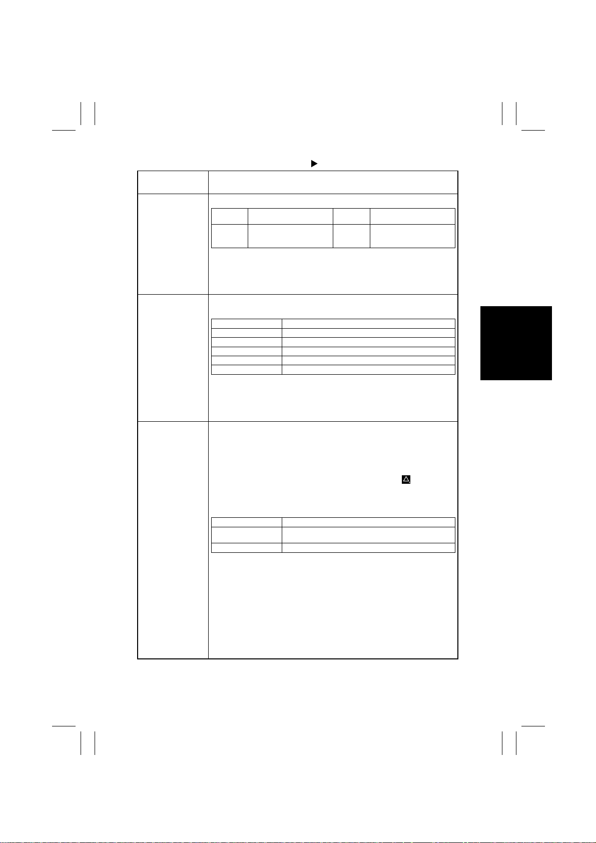
98.11.25
Tech. Rep. Mode Counter
Touch Panel
Display
Operation
Trouble <Trouble Counter 5/5>
Malfunction
Code
C133B
C13C0
C13D0
Location
Communication Error (Option)
I/C Initial Error
EEPROM
Malfunction
Code
C13F0
C18XX
Location
HSYNC (SOS)
Printer Controller Error
<Clearing a Count>
Touch the item key whose count is to be cleared and press the Clear
key. If a count is accidentally cleared, pressing the Interrupt key will
undo the clear operation.
Device Shows the numbers of prints for different applications. It also allows
the Tech. Rep. to clear each counter.
Display Description
Copier No. of prints made by copier
Printer No. of prints made by printer
Report Print No. of report prints made
Fax Print No. of fax prints made
Fax Transmission No. of prints made for fax transmission
<Clearing a Count>
Select the counter to be cleared with the item ke y and press the Clear
key. If the count is accidentally cleared, pressing the Interrupt key will
undo the clear operation.
Maintenance
•
This function allows the Tech. Rep. to set the number of copies to
be made before the Maintenance Call reminder is given. (1k ~
9999k)
•
It shows the current count value and the above setting. Each
counter may be reset to 0 independently of the others:
•
When the count reaches the preset value, the icon “ ” appears in
the Status Display.
✽
When “Call Indicated” is selected for “Maintenance Call” available
from Tech. Rep. Choice.
Display Description
Maintenance (Set) The Maintenance Call reminder is given when the count
Maintenance (Count) Counts one for each copy made.
reaches the preset value.
<Setting a Count>
1. To uch [Maintenance (Set)] and then press the Clear key to clear
the count. If the count is accidentally cleared, pressing the interrupt key will undo the clear operation.
2. Enter the desired value from the 10-Key Pad.
<Clearing a Count>
Touch [Maintenance (Count)] and then press the Clear key to clear
the count. If the count is accidentally cleared, pressing the interrupt
key will undo the clear operation.
S-27
Page 31
FrameMaker Ver.5.5(PC) Di350 SWITCHES ON PWBs/TECH. REP. SE TTINGS
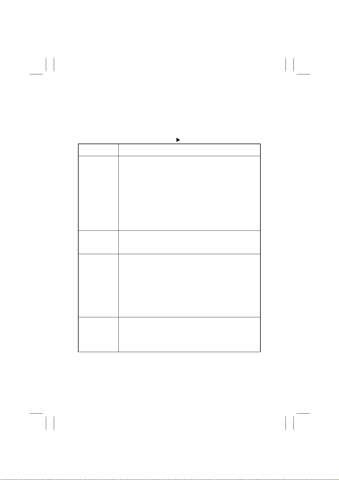
98.11.25
(5) Function
•
This function allows the Tech. Rep. to run the various function tests and make adjustments.
<Setting Procedure>
1. Touch [Function] to open the Function menu screen.
2. Select the particular function to be run.
Tech. Rep. Mode Function
Touch Panel
Display
F1 <Paper Passage>
A paper passage test is carried out after the copier has completed
warming up.
<Procedure>
1. Select the paper source key. (Touch [Duplex] to check for paper
passage from the Duplex Unit.)
✽
If the paper source is not loaded with paper, an Add Paper mark
appears at that source.
2. Press the Start key to start the test cycle. The test runs until the
paper source runs out of paper.
3. If the Stop key is pressed, the copier feeds the current sheet of
paper out before halting. (Another press of the Start key will
resume the test cycle.)
F2 <HV Output Setting>
F7-1 <Original Size Detecting Sensor Adjustment>
F8 <ATDC Sensor Automatic Adjustment>
Set the output of each HV.
✽
This function is only for factory setting and should never be used in
the field.
Automatically adjusts the Original Size Detecting Sensors.
<Procedure>
1. Stack five sheets of A3 or 11” × 17” paper on the Original Glass
and lower the Original Cover.
2. Press the Start key to let the system start the adjustment
sequence.
✽
The system automatically stops as soon as the adjustment
sequence is completed. It can nonetheless be halted in midsequence with the Stop key, which, however, results in incorrect
size detection as the adjustment sequence is incomplete.
Automatically makes the ATDC Sensor adjustment.
<Procedure>
Press the Start key to let the system start the adjustment sequence.
✽
The voltage automatically adjusted by this function is displayed for
ATDC Sensor Gain of the Level History data.
Operation
S-28
Page 32
FrameMaker Ver.5.5(PC) Di350 SWITCHES ON PWBs/TECH. REP. SE TTINGS
98.11.25
Tech. Rep. Mode Function
Touch Panel
Display
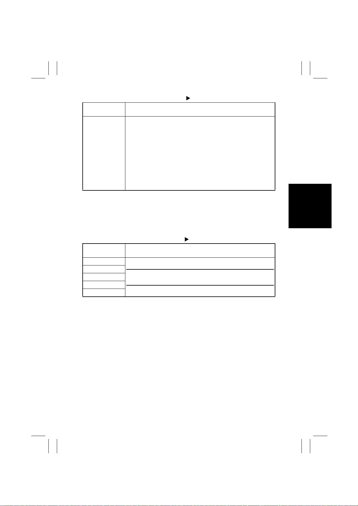
F12 <Test Pattern>
(6) I/O Check
•
This function displays the details of inputs to each sensor.
<Setting Procedure>
1. Touch [I/O Check] to open the I/O Check menu screen.
2. Touch the desired subfunction key.
Touch Panel
Display
Scan-through ADF
IR
ADFR
Output Option
Printer
Outputs a test pattern.
✽
If 2-sided is specified, the system outputs a test pattern in the 2sided mode.
<Procedure>
1. To uch the desired paper source key. (Touch [Duplex] for test pattern output on paper fed from the Duplex Unit.)
✽
If the paper source is not loaded with paper, an Add Paper mark
appears at that source.
2. Press the Start key to start the output sequence. (It continues until
the paper source runs out of paper.)
3. Press the Stop key to halt the sequence.
Tech. Rep. Mode I/O Check
NOTE
•
For details, see TROUBLESHOOTING.
Operation
Operation
S-29
Page 33
FrameMaker Ver.5.5(PC) Di350 SWITCHES ON PWBs/TECH. REP. SE TTINGS
98.11.25
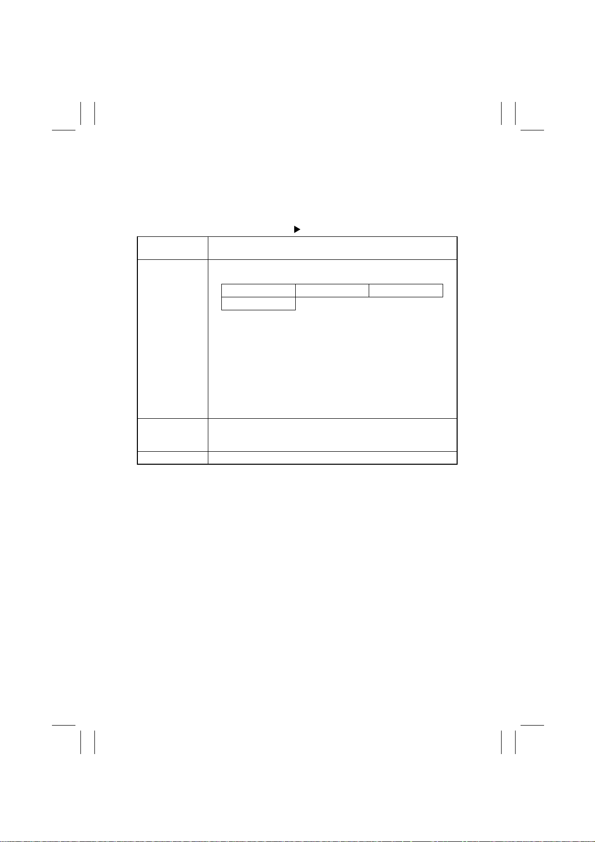
(7) Movement Check
•
This function runs a specified mechanism to check for operation.
<Setting Procedure>
1. Touch [Movement Check] to open the Movement Check menu screen.
2. Touch the desired subfunction.
Tech . Rep. Mode Movement Check
Touch Panel
Display
ADF Paper Passage
Scanner
Exp. Lamp Check Checks for the intensity of the Exposure Lamp light.
Feeds paper through the ADF in the specified mode to check for correct operation.
1-sided No Detect 1-sided Mixed Orig 2-sided
SADF
<Procedure>
1. Select ADF Paper Passage.
2. To uch the desired mode key.
3. Load originals in the ADF.
4. Press the Start key to let the ADF start feeding originals.
✽
Pressing of the Start key temporarily stops the ADF. (Another press
will let the ADF resume the sequence.)
✽
The sequence is completed when there is no more originals in the
ADF; however, it is possible to halt the sequence in mid-operation
by pressing the Stop key.
•
Drives the CCD.
•
Turns ON the Exposure Lamp.
•
Moves the Scanner according to the set value.
Operation
S-30
Page 34
FrameMaker Ver.5.5(PC) Di350 SWITCHES ON PWBs/TECH. REP. SE TTINGS
98.11.25
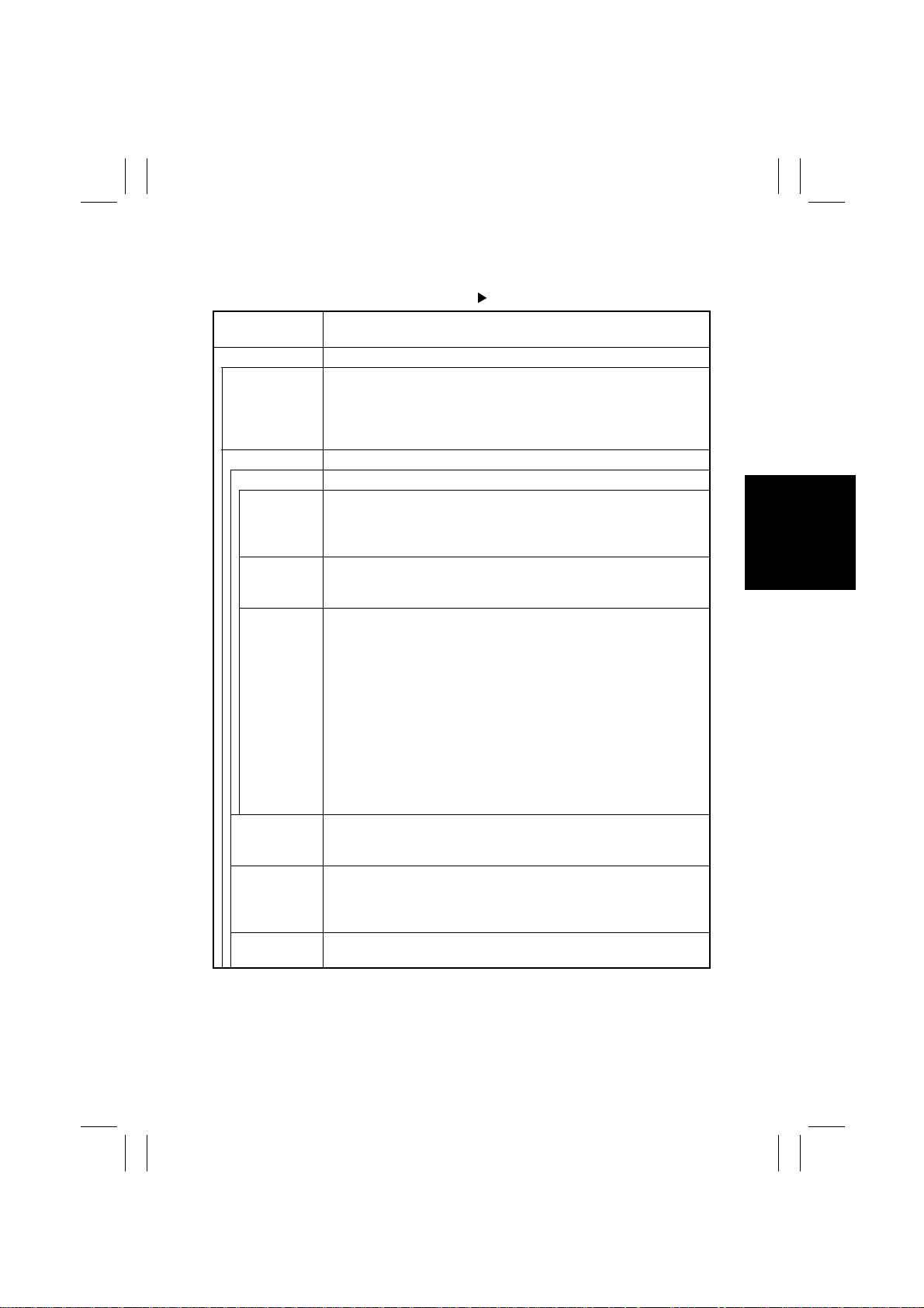
(8) RD Mode (SMART)
✽
“SMART” is displayed for the inch areas.
Tech. Rep. Mode RD Mode
Touch Panel
Display
RD Mode For making the initial settings of the copier for the Data Terminal.
ID Code Enter a 7-digit ID code (0000001 to 9999999) from the 10-Key Pad t o
Maintenance Used to make the initial settings and various transmissions.
DT Setting Enter the following data.
CT-ID
(Password)
DT-ID Using the 10-Key Pad, enter the 6-digit ID number (000001 to
TEL No. Enter the 19-or-less-digit phone number of the modem connected to
Initial Transmission
Counter Clear Used to clear the count of the spare counter set by the Center.
Call Completion
enable making the following settings. When the ID code is entered
and transmitted after the initial settings have been made, it executes
the transmission of MAINT. START to the Center.
✽
0000000 is invalid.
Using the 10-Key Pad, enter the 4-digit ID number (0001 to 9999) of
the Center which has been programmed in the Center personal computer.
✽
0000 is invalid.
999999) of the Data Terminal.
✽
000000 is invalid.
the Center personal computer from the 10-Key Pad.
✽
In addition to the 10-Key Pad and Clear k ey, use the foll owing keys
to enter the phone number.
Interrupt key: For a pause (3 sec. or more), “-”
Pause key: For a pause (3 sec. or more), “-”
P key: For a “pulse” dialing, “P”
T key: For a “tone” dialing, “T”
W key: For a wait code (waiting for a signal from the other party),
“W”
✽
key: For an ISDN subaddress, “✽”
# key: For switching from the extension line to outside line, or vice
versa, “#”
Used to perform the initial transmission from the copier to the Center
to check for correct communication when the Data Terminal has been
set up.
<Procedure>
1. Touch [Counter Clear] to open the Counter Clear screen.
2. Touch the number assigned to the counter to be cleared.
Used by the Tech. Rep. to notify the Center that his/her service job for
the copier has been completed.
Setting
S-31
Page 35
FrameMaker Ver.5.5(PC) Di350 SWITCHES ON PWBs/TECH. REP. SE TTINGS
Highlighted
98.11.25
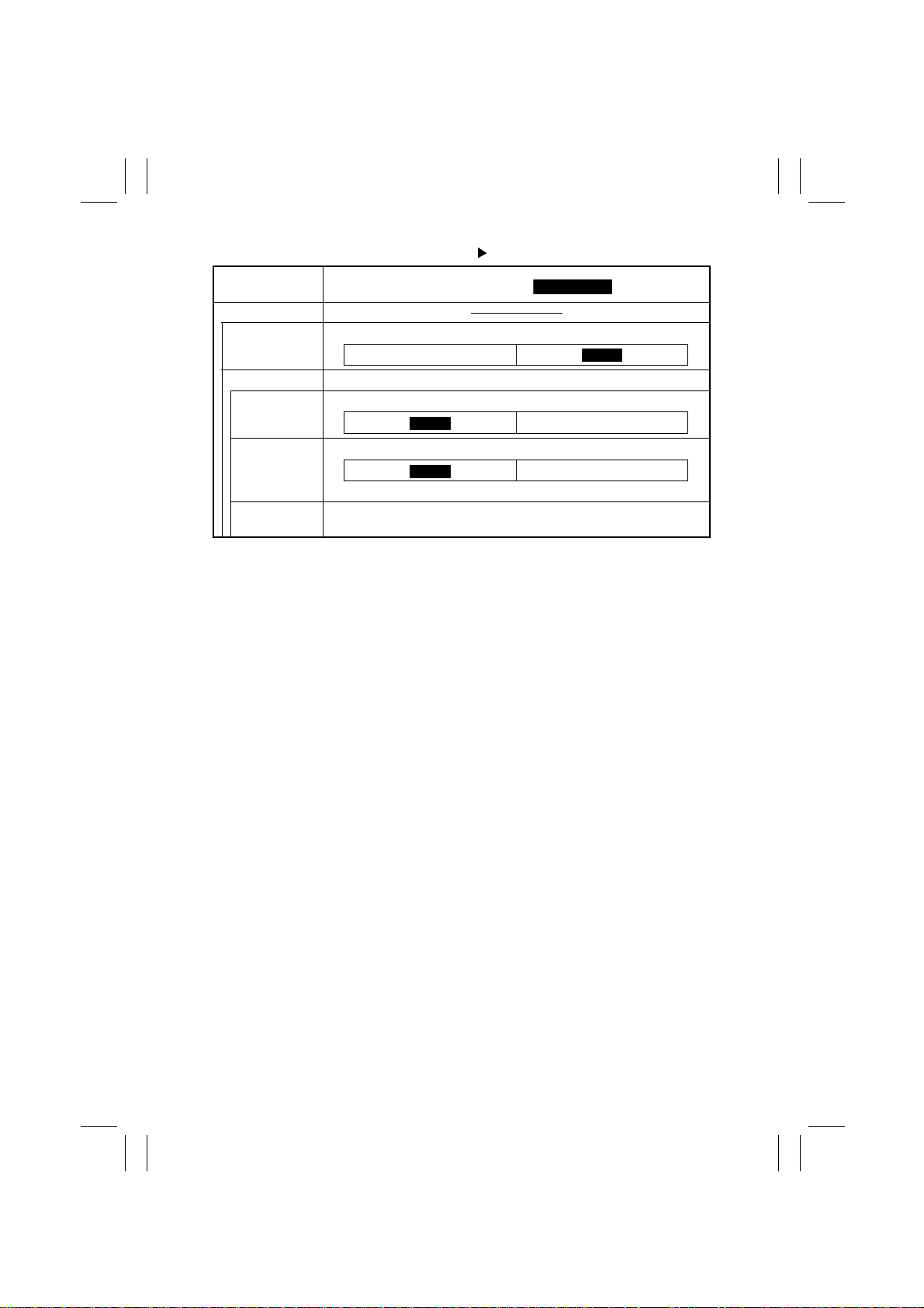
Tech. Rep. Mode RD Mode
Touch Panel
Display
RD Mode
RAM Clear Reinitializes the Data Terminal.
Common DT Set the following functions.
Dial Mode Se lect the type of telephone line of the user.
Auto Receive Choose “Yes” or “No” for the auto reception function.
✽
Select “Yes” if the line is dedicated to the Data Terminal.
Result Code Enter the result code for connection to the modem when the line is
connected. (0 to 999)
Setting (The default is ).
YES
Tone
YES
NO
Pulse
NO
S-32
Page 36
FrameMaker Ver.5.5(PC) Di350 SWITCHES ON PWBs/TECH. REP. SE TTINGS
98.11.25
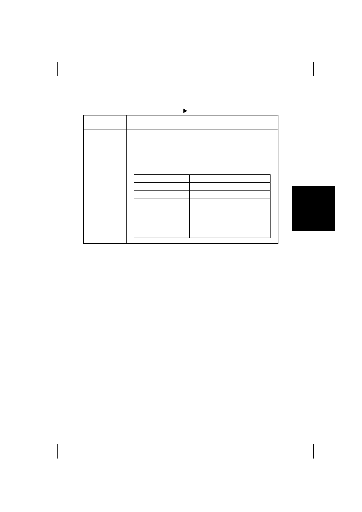
(9) ROM Version
Tech. Rep. Mode ROM Ver sion
Touch Panel
Display
ROM Version Displays the current ROM version information.
✽
No version information is displayed for a machine that is not connected to the system.
<Procedure>
1. Touch [ROM Version] to open the ROM Version screen.
2. The screen shows the ROM version information of various
machines configured in the system.
Display Description
MSC — MFB Board
Message IC4 MFB Board
Printer IC1 Master Board
ADFR IC3 ADFR Board
LCC IC7 LCC Board
Finisher IC3 Finisher/Job Tray Board
IIF — IIF2 Board
Operation
S-33
Page 37
FrameMaker Ver.5.5(PC) Di350 SWITCHES ON PWBs/TECH. REP. SE TTINGS
98.11.25
(10) Level History
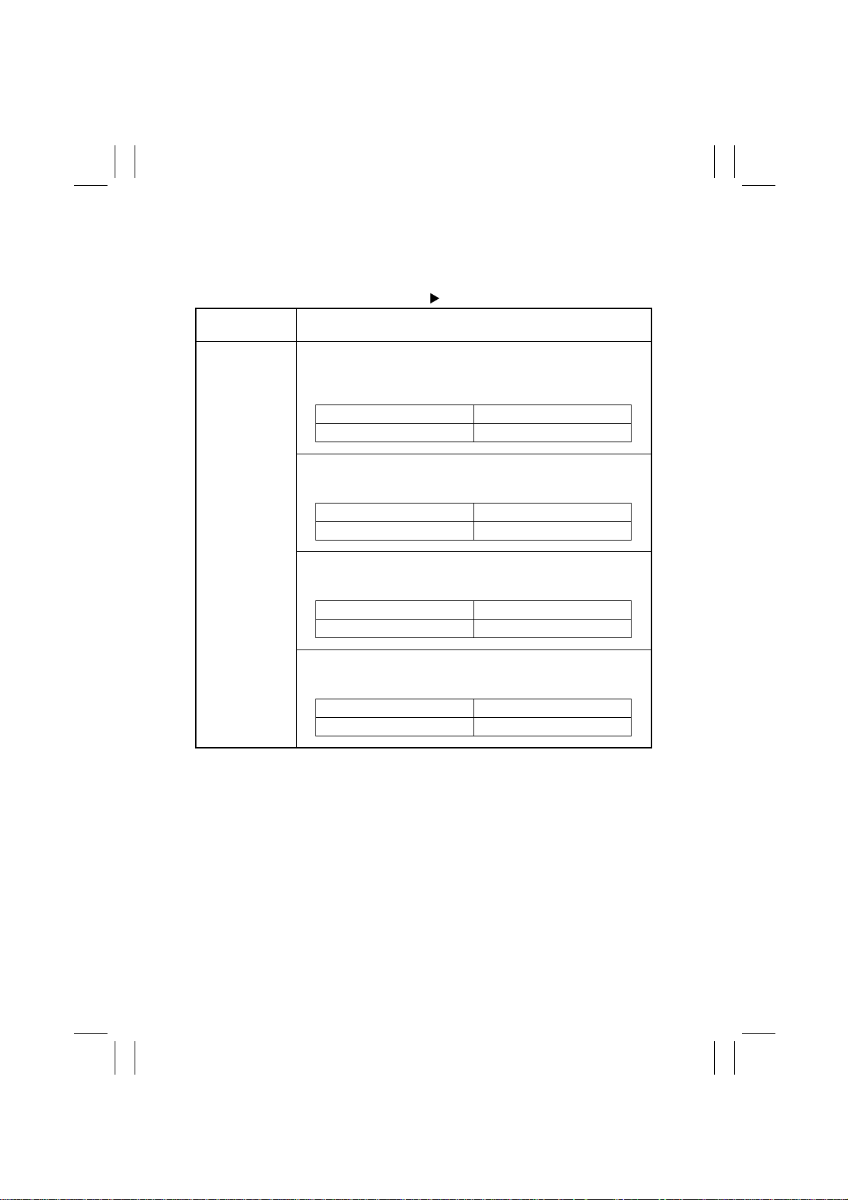
•
This function is used to show the various level histories which are changed according to
the operating conditions of the copier and user requirements.
Tech. Rep. Mode Level History
Touch Panel
Display
Level History <ATDC Set>
Shows the voltage set by ATDC Sensor Automatic Adjustment (F8).
✽
The Level History data is updated when the ATDC Sensor Automatic Adjustment (F8) is completed.
Variab le Range Increments
123 to 186 (steps) 1 Step
Shows the current, approximate ATDC Sensor T/C setting in percentage.
Variab le Range Increments
3.0 to 19.0 (%) 0.5%
Setting
<ATDC Current>
Displays the grid v oltage as corrected through image stabilization and
related functions.
Variab le Range Increments
-534 to -748 (V) -
Displays the developing bias voltage as corrected through image stabilization and related function.
Variab le Range Increments
-409 to -623 (V) -
<Vg Current>
<Vb Current>
S-34
Page 38
FrameMaker Ver.5.5(PC) Di350 SWITCHES ON PWBs/TECH. REP. SE TTINGS
98.11.25
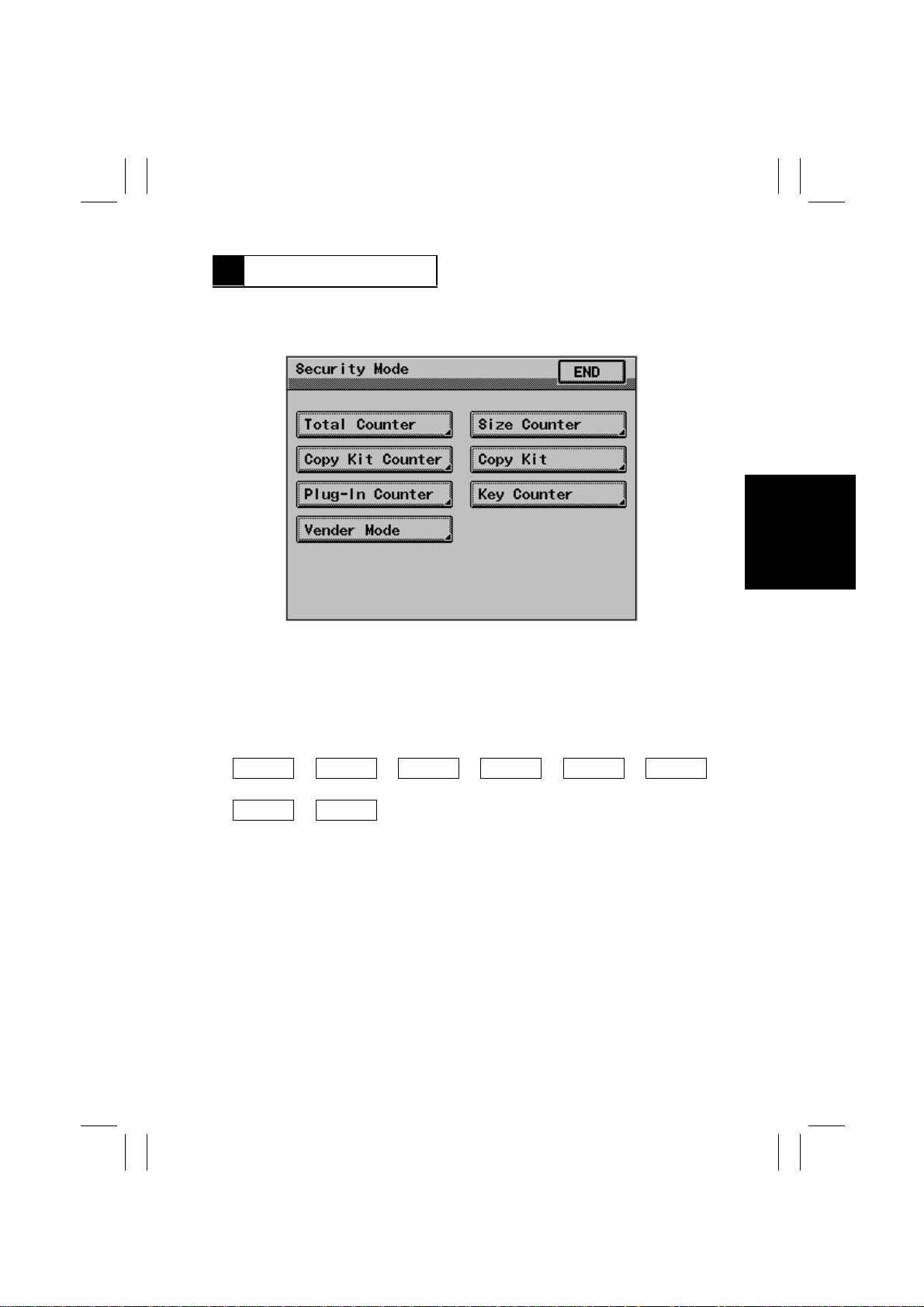
6 SECURITY MODE
•
This function allows the Tech. Rep. to make various settings.
6-1. Security Mode Menu Screen
1167S011CA
6-2. Security Mode Function Setting Procedure
<Setting Procedure>
1. Set the copier into the Tech. Rep. mode by one of the fol l owing methods:
A. With the copier turned ON, press the Tech. Rep. Setting Switch.
B. With the Meter Count screen opened from Utility, press the following keys in this
order:
Stop Key
2. Enter the Security mode by pressing the following keys in this order:
Stop Key
3. Select the particular Security mode to be set.
4. Make the necessary settings by following the instructions given sequentially on the
screen.
✽
The Function selected is highlighted.
<Exiting the Mode>
Perf orm any one of the following steps to go back to the Basic screen.
•
Press the Panel Reset key and Touch [Exit] on the Tech. Rep. Mode screen.
•
Touch [END] on the Security Mode screen. Then touch [Exit] on the Tech. Rep. Mode
screen.
➡
➡
➡
0
9
➡
0
Stop Key
➡
➡
0
1
S-35
Page 39
FrameMaker Ver.5.5(PC) Di350 SWITCHES ON PWBs/TECH. REP. SE TTINGS
Highlighted
98.11.25
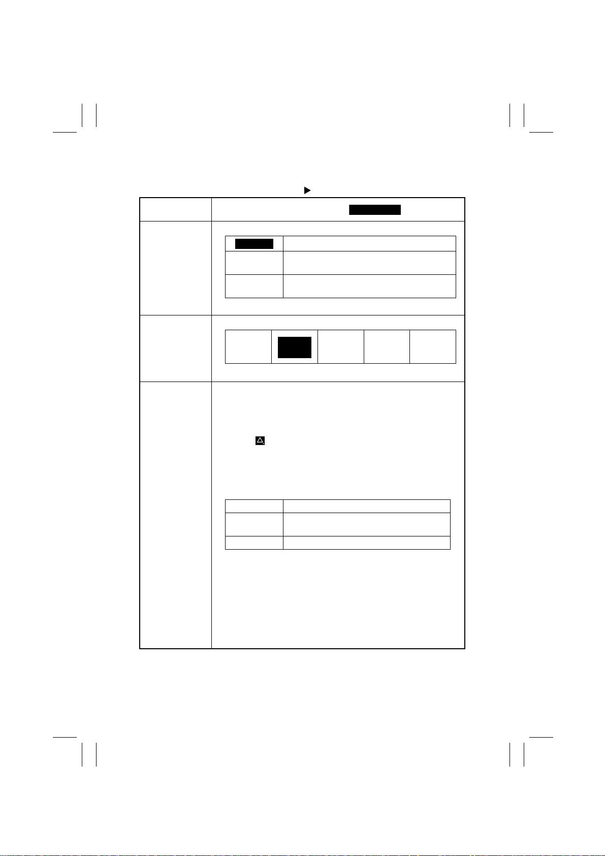
6-3. Settings in the Security Mode
Tech. Rep. Mode Security Mode
Touch Panel
Display
Total Counter Select the conditions by which the Tot al Counter count is increased.
✽
See the Count-up Table for details .
Size Counter Select the size of the paper to be counted by the Size Counter.
No Count
✽
See the Count-up Table for details .
Copy Kit
•
Allows for setting the desired threshold before the Maintenance Call
reminder is given.
•
Displays both the current value and the above setting value. Each
counter can also be reset independently of the other.
•
When the current value (Current) becomes the setting value (Set),
the icon “ ” appears in the Status Display if “Mode 2” is selected
for “Copy Kit Counter” and the Maintenance Call reminder (M4) is
displayed if “Mode 3” is selected for “Copy Kit Counter.”
✽
Whether the initiation of a new copy cycle is inhibited or not when
the current value exceeds the setting value depends on the setting
made with Copy Kit Counter.
Set Gives a Maintenance Call when Current
Current Counts up for each copy made.
Setting (The default is ).
Mode 1
Mode 2
Mode 3
Display Description
1 count per 1 copy cycle (normal mode)
Multiple count-up according to paper size and
1/2-sided copying
Multiple count-up according to paper size and
1/2-sided copying
A3
11×17
value reaches Set value.
A3 / B4
11×17
Legal
A3 /11×17
B4 /11×14
FLS/Legal
A6
<Counter Setting Procedure>
1. Touch [Set] and press the Clear k ey to clear the current setting. If
the setting is accidentally cleared, pressing of the Interrupt ke y will
undo the clear operation.
2. Enter the desired value from the 10-Key Pad.
<Clearing the Count>
Touch [Current] and press the Clear key to clear the count. If the
count is accidentally cleared, pressing of the Interrupt key will undo
the clear operation.
S-36
Page 40
FrameMaker Ver.5.5(PC) Di350 SWITCHES ON PWBs/TECH. REP. SE TTINGS
Highlighted
98.11.25
Tech. Rep. Mode Security Mode
Touch Panel
Display
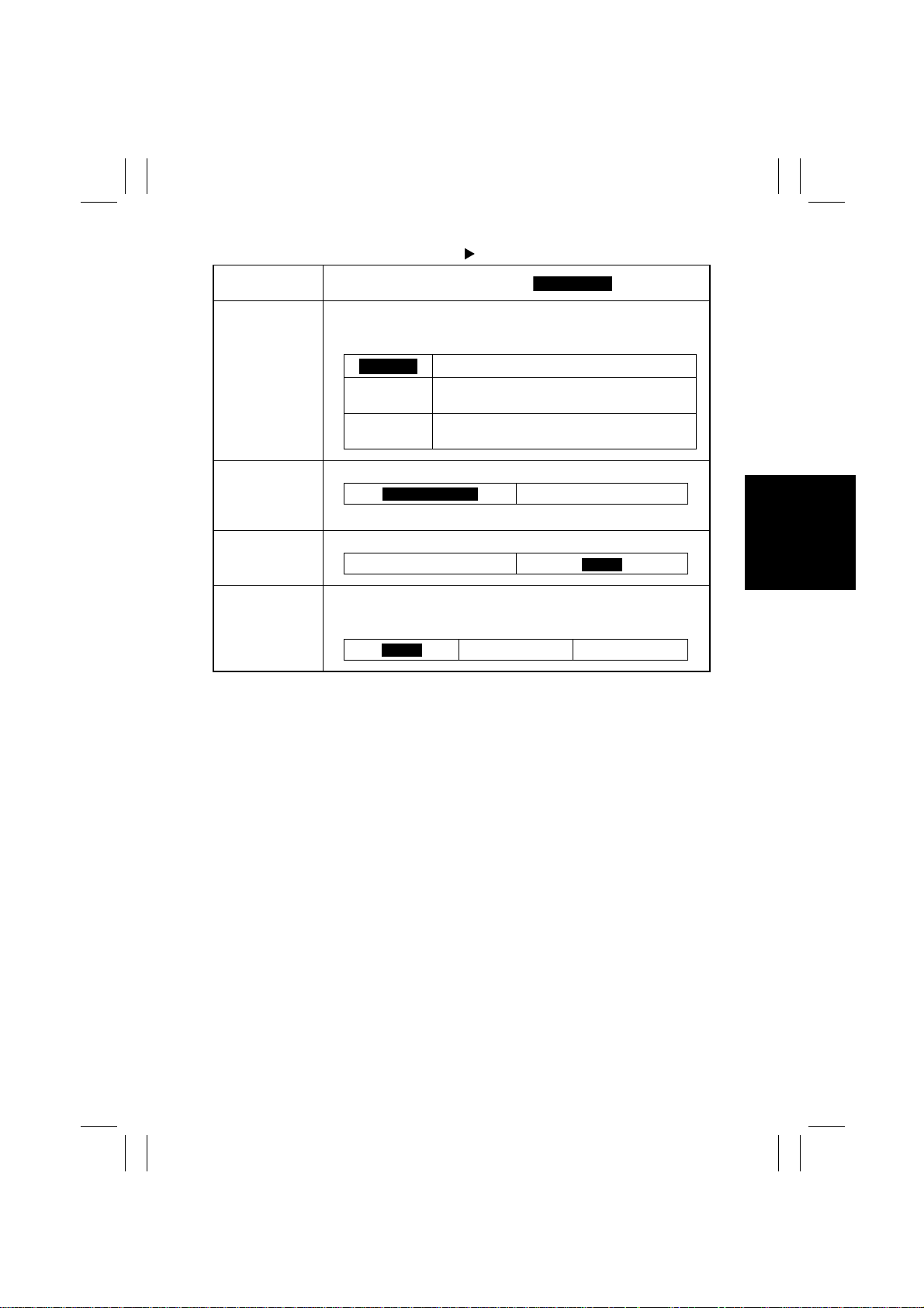
Copy Kit Counter Select whether to set the count or not for the Copy Kit Counter and
Plug-In Counter Select the condition by which the Key Counter count is increased.
Key Counter Set whether a Key Counter is plugged in (“ON”) or not (“OFF”).
select whether to inhibit the initiation of a new copy cycle or not when
the Current value reaches Set value.
✽
See the Count-up Table for details .
Setting (The default is ).
Mode 1
Mode 2
Mode 3
No counting
Counted and permits copying even when the
Set value is reached.
Counted and inhibits copying when the Set
value is reached.
Copies Made
ON
Copy Cycles
OFF
Vender Mode Select the medium to be used when the Key Counter or Vender is
used.
✽
This function is not valid if “OFF” is selected for “Key Counter.”
OFF
Coin Card
S-37
Page 41
FrameMaker Ver.5.5(PC) Di350 SWITCHES ON PWBs/TECH. REP. SE TTINGS
98.11.25
Tech. Rep. Mode Security Mode
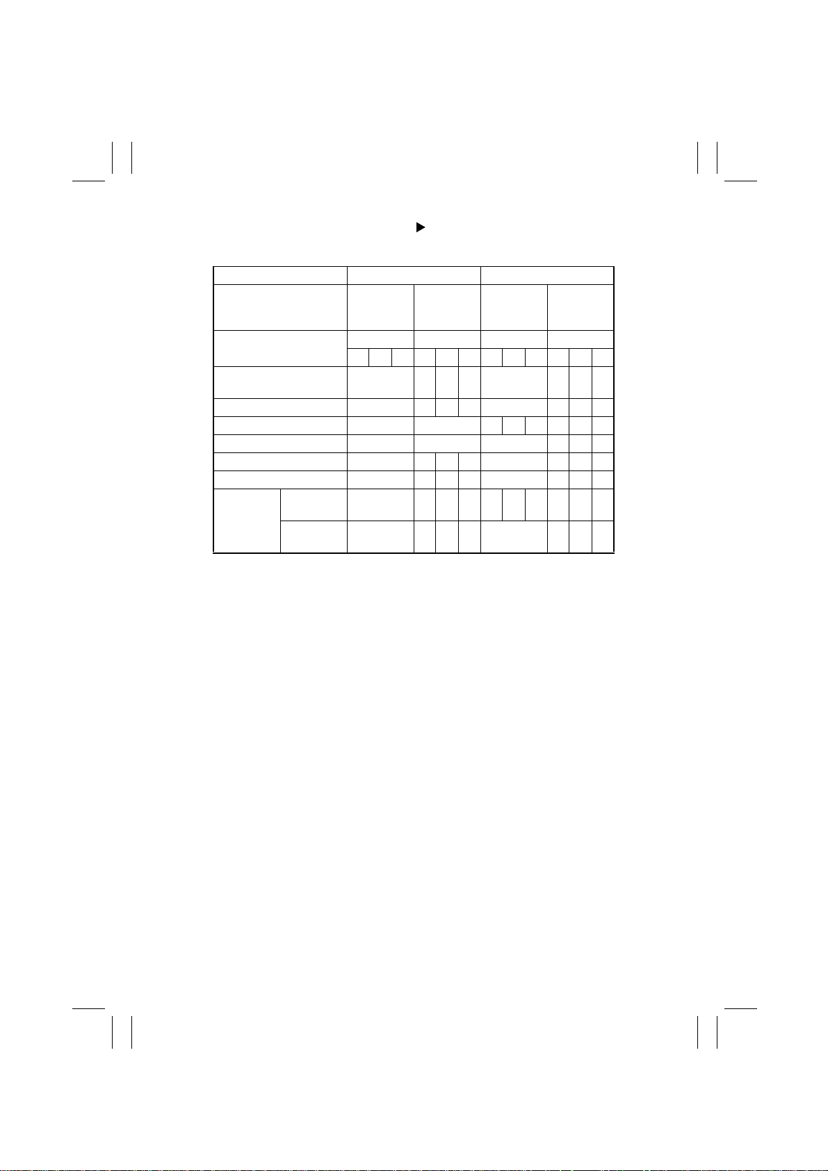
<Count-up Table>
Copying 1-Sided 2-Sided
Size Size other
Total Mode Mode Mode Mode
Total (mechanical, electronic)
Size (electronic) 0 1 1 2 0 2 2 0
2-Sided Total (electronic) 0 0 1 1 2 1 1 4
2-Sided Size (electronic) 0 0 0 1 1 4
Total by account 1 1 2 2 2 2 4 4
Size by account 0 1 1 2 0 2 2 4
Key
(mechanical)
0: No count 1: 1 count 2: 2 counts 3: 3 counts 4: 4 counts
Counting
copies
Counting
copy cycles
than those
set
123123123123
11222244
1 122122144
11222244
Set size
Size other
than those
set
Set size
S-38
Page 42
FrameMaker Ver.5.5(PC) Di350 SWITCHES ON PWBs/TECH. REP. SE TTINGS
98.11.25
7 ADJUST MODE
•
Adjust mode is for adjustments to be made before shipment at the factory. As a rule, use
this mode only when MFB Board UN2, or EEPROM (IC3A) on Master Board PWB-A has
been replaced with a new one.
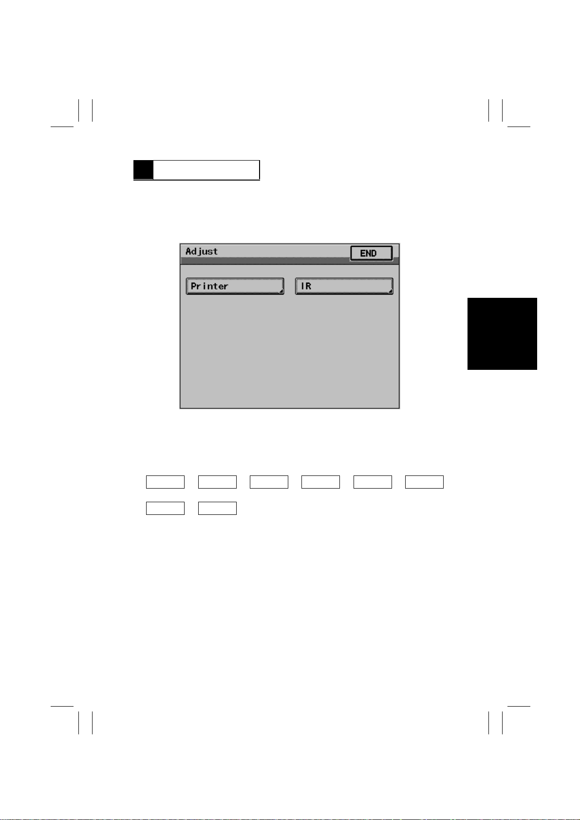
7-1. Adjust Mode Menu Screen
1167S012CA
7-2. Adjust Mode Function Setting Procedure
<Setting Procedure>
1. Set the copier into the Tech. Rep. mode by the following method:
•
With the Meter Count screen opened from Utility, press the f ollowing keys in this order .
Stop Key
2. Enter the Adjust mode by pressing the following keys in this order:
Stop Key
3. Select the particular Adjust mode function to be set.
4. Make the necessary settings by following the instructions given sequentially on the
screen.
✽
The function selected is highlighted.
<Exiting the Mode>
Perf orm any one of the following steps to go back to the Basic screen.
•
Press the Panel Reset key and Touch [Exit] on the Tech. Rep. Mode screen.
•
Touch [END] on the Adjust mode screen. Then touch [Exit] on the Tech. Rep. Mode
screen.
➡
➡
Start Key
➡
0
➡
0
Stop Key
➡
➡
0
1
S-39
Page 43
FrameMaker Ver.5.5(PC) Di350 SWITCHES ON PWBs/TECH. REP. SE TTINGS
Highlighted
98.11.25
7-3. Adjust Mode Function Tree
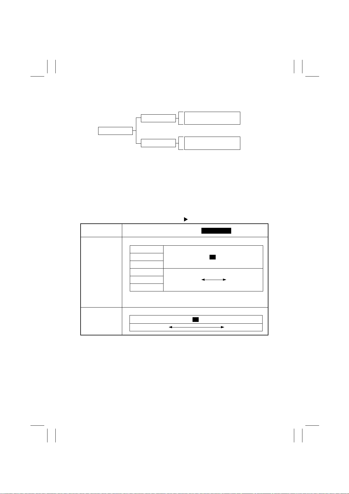
Printer
Adjust
IR
Registration (CD)
Registration (FD)
Registration
Zoom Adjust
7-4. Settings in the Adjust Mode
(1) Printer
•
This function is used to enter the adjustment values as they relate to the printer.
<Setting Procedure>
1. Touch [Printer] to open the Printer screen.
2. Select the desired subfunction.
Tech. Rep. Mode Adjust
Touch Panel
Display
Registration (CD) Adjust registration of the printer in the main scanning direction.
1st Drawer
2nd Drawer
3rd Drawer
4th Drawer
Setting (The default is ).
-4.0mm...................... .....................+4.0mm
Advanced timing Retarded timing5th Drawer
Duplex
0
✽
Adjust “Duplex” after adjustments have been completed for all
drawers.
Registration (FD) Adjust registration of the printer in the sub-scanning direction.
-19.......................................... .........................................+19
Advanced timing
0
Retarded timing
S-40
Page 44
FrameMaker Ver.5.5(PC) Di350 SWITCHES ON PWBs/TECH. REP. SE TTINGS
Highlighted
1.000
98.11.25
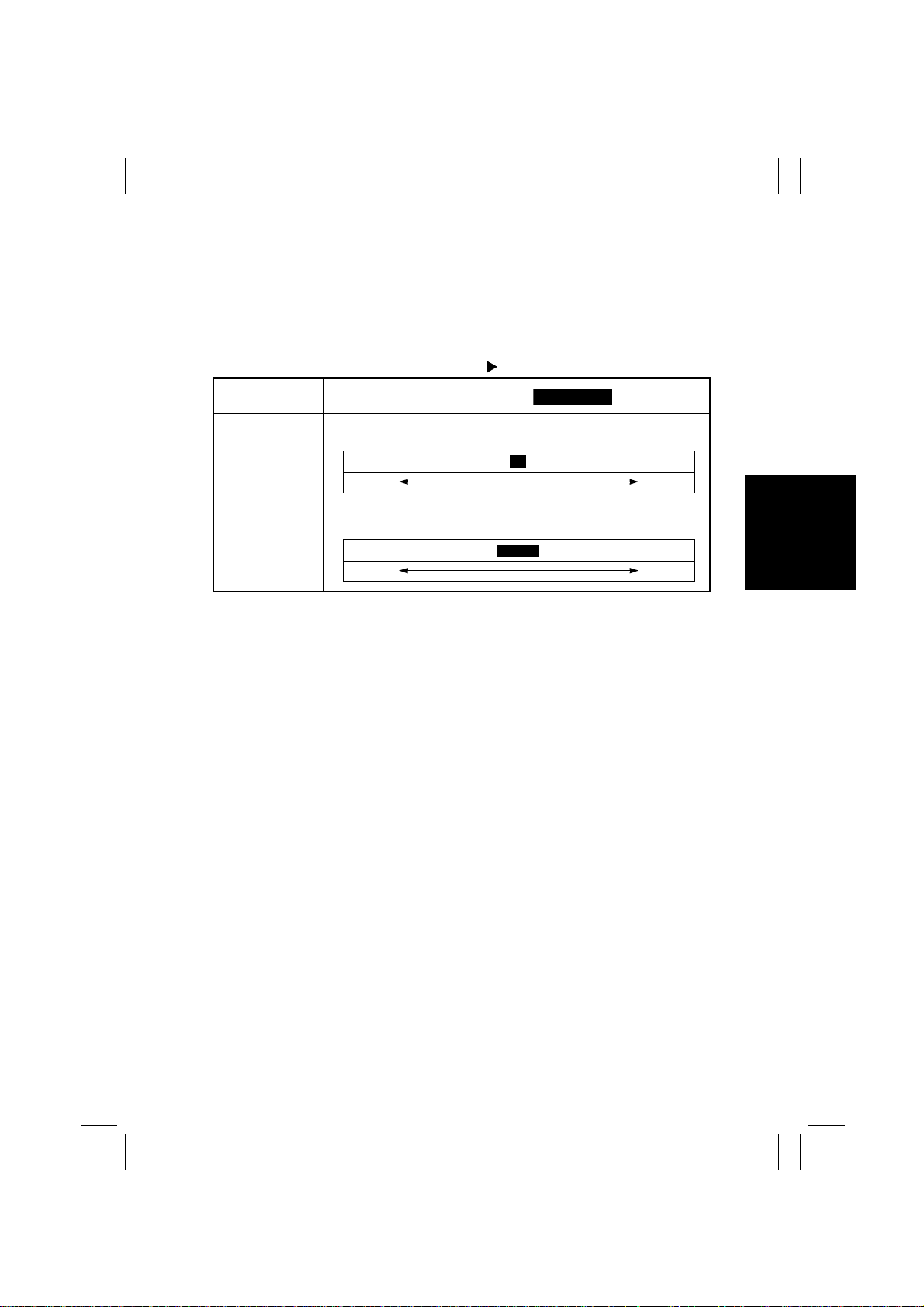
(2) IR
•
This function is used to enter the adjustment values as they relate to the IR.
<Setting Procedure>
1. Touch [IR] to open the IR screen.
2. Select the desired subfunction.
Tech. Rep. Mode Adjust
Touch Panel
Display
Registration Adjust registration of the Scanner in the main and sub-scanning direc-
tions.
-127 dot.................................. .................................+127 dot
Smaller
Zoom Adjust Adjust the scanning zoom ratio of the Scanner in the main and sub-
scanning directions.
0.990.................................. ..................................1.010
Smaller
Setting (The default is ).
0
Greater
Greater
S-41
Page 45
FrameMaker Ver.5.5(PC) Di350 SWITCHES ON PWBs/TECH. REP. SE TTINGS
98.11.25
8 INITIAL MODE
•
Initial mode is used to initialize the various service functions.
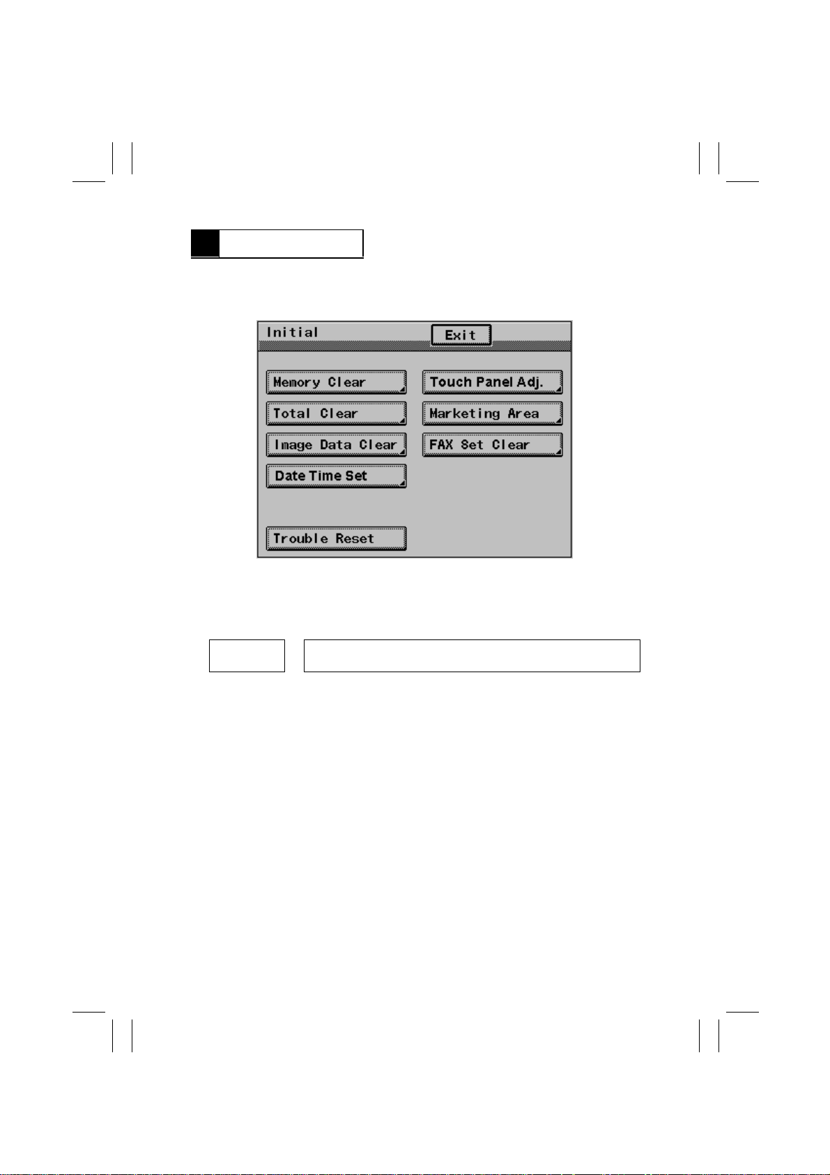
8-1. Initial Mode Menu Screen
1167S013CB
8-2. Initial Mode Function Setting Procedure
<Setting Procedure>
1. Enter the Initial mode by pressing the following keys in this order:
Warm Restart
Switch ON
2. Select the particular Initial mode function to be set.
3. Make the necessary settings by following the instructions given sequentially on the
screen.
✽
The function selected is highlighted.
<Exiting the Mode>
•
Touch [Exit] on the Initial mode screen to go back to the Basic screen.
Enter “3” from the 10-Key Pad when “. ” appears at the center on the
➡
left side of the screen while the start-up screen is being displayed.
S-42
Page 46
FrameMaker Ver.5.5(PC) Di350 SWITCHES ON PWBs/TECH. REP. SE TTINGS
Highlighted
98.11.25
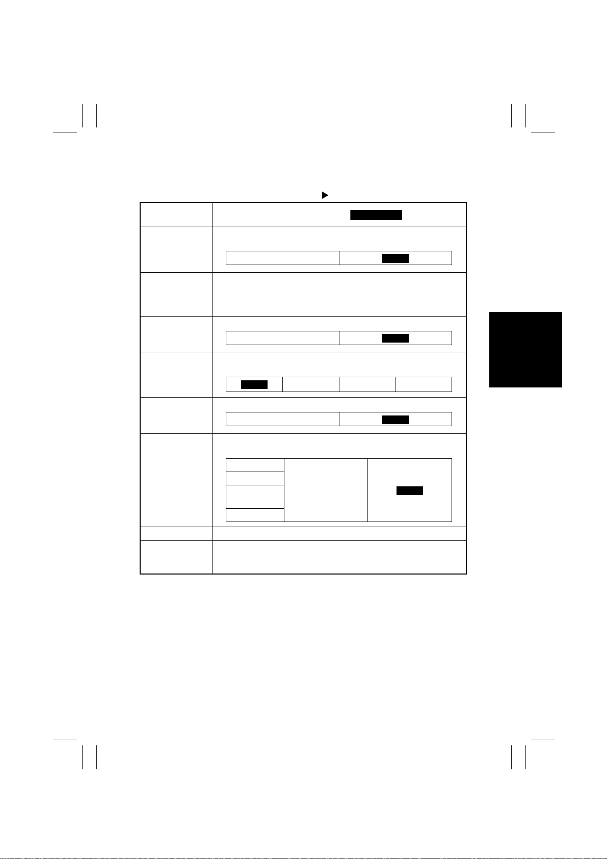
8-3. Settings in the Initial Mode
Tech. Rep. Mode Initial
Touch Panel
Display
Memory Clear Clears all data except the electronic counters, Adjust, Copy Track-
related, and DT-related settings.
Setting (The default is ).
Yes
NO
Touch Panel Adj. Corrects deviation in the sensitive area of the Touch Panel.
Total Clear Clears all of the electronic counters and Copy Track-related data.
Marketing Area Selects the settings for the fixed zoom ratios, paper sizes, and others
Image Data Clear Clears the image data stored in file memory of the MFB Board.
FAX Set Clear Clears the fax-related settings.
Date Time Set Sets the time-of-day and date.
Trouble Reset Resets all malfunctions including the Fusing ones (C05XX).
<Procedure>
Sequentially touch the four points marked with + on the screen as
instructed by the arrow.
Yes
according to the marketing area.
MJ
✽
Two or more items can be selected.
Own Setting
The Address
Transmission
Manage
Soft Switch
✽
Malfunctions other than Fusing ones can be reset by turning OFF
and ON the Power Switch and opening and closing the Side Cover.
MC MH
Yes
Yes
NO
Others
NO
NO
S-43
 Loading...