

Page 1
PagePro™9100 Series
.minolta-qms.com
1750053-001A
Service Manual
The essentials of imaging
www.minolta-qms.com
Page 2

Trademarks
The following are registered trademarks of MINOLTA-QMS, Inc.: QMS and the
MINOLTA-QMS logo. Minolta, and PagePro are trademarks of Minolta Co., Ltd.
Other product names mentioned in this guide may also be trademarks or
registered trademarks of their respective owners.
Proprietary Statement
The digitally encoded software included with your printer is Copyrighted © 2002
by MINOLTA-QMS, Inc. All Rights Reserved. This software may not be
reproduced, modified, displayed, transferred, or copied in any form or in any
manner or on
any media, in whole or in part, without the express written permission of
MINOLTA-QMS, Inc.
Copyright Notice
This manual is Copyrighted © 2002 by MINOLTA-QMS, Inc., One Magnum Pass,
Mobile, AL 36618. All Rights Reserved. This document may not be copied, in
whole or part, nor transferred to any other media or language, without written
permission of MINOLTA-QMS, Inc.
Manual Notice
MINOLTA-QMS, Inc. reserves the right to make changes to this manual and to the
equipment described herein without notice. Considerable effort has been made to
ensure that this manual is free of inaccuracies and omissions. However,
MINOLTA-QMS, Inc. makes no warranty of any kind including, but not limited to,
any implied warranties of merchantability and fitness for a particular purpose with
regard to this manual. MINOLTA-QMS, Inc. assumes no responsibility for, or
liability for, errors contained in this manual or for incidental, special, or
consequential damages arising out of the furnishing of this manual, or the use of
this manual in operating the equipment, or in connection with the performance of
the equipment when so operated.
Page 3

CONTENTS
1. Safety Precautions for Inspection and Service ............................................................. 1
1-1. Outlines of safety precautions ............................................................................. 1
1-2. Warning ............................................................................................................... 1
1-3. Caution ................................................................................................................ 4
1-4. Other precautions ................................................................................................. 6
1-5. Precautions for service ........................................................................................ 8
1-6. Safety information ............................................................................................... 11
(1) Laser Safety ................................................................................................ 11
(2) Internal Laser Radiation ............................................................................. 11
1-7. Laser safety label ................................................................................................. 14
1-8. Laser caution label ............................................................................................... 14
1-9. Precautions for handling the equipment .............................................................. 14
2. INSTALLATION ......................................................................................................... 15
2-1. Installation environment ...................................................................................... 15
2-2. Usage environment .............................................................................................. 16
2-3. Installing the power supply ................................................................................. 16
2-4. Space requirements .............................................................................................. 17
(1) Standard ...................................................................................................... 17
(2) With options installed ................................................................................. 17
3. GENERAL INFORMATION ..................................................................................... 19
3-1. Specifications ...................................................................................................... 19
(1) Printer ....................................................................................................... 19
(2) 500-sheet lower feed unit (optional) ........................................................... 22
(3) Duplex unit (optional) ................................................................................ 23
(4) 4-bin mailbox (optional) ............................................................................. 23
3-2. Parts identification ............................................................................................... 24
3-3. Component diagram ............................................................................................ 26
3-4. Drive system ........................................................................................................ 27
(1) Overview of the drive system for the standard configuration .................... 27
(2) Diagram of the drive system for the standard configuration ...................... 28
(3) Overview of the drive system when options are installed .......................... 29
3-5. Electrical components layout .............................................................................. 30
(1) Printer ....................................................................................................... 30
(2) Lower feed unit (optional) .......................................................................... 32
(3) Duplex unit (optional) ................................................................................ 32
(4) 4-bin mailbox (optional) ............................................................................. 33
3-6. Electrical components functions .......................................................................... 34
(1) Printer ....................................................................................................... 34
(2) Lower feed unit (optional) .......................................................................... 35
(3) Duplex unit (optional) ................................................................................ 36
(4) 4-bin mailbox (optional) ............................................................................. 36
1
i
Page 4

(5) PWB-A (main control board) ..................................................................... 37
(6) PWB-D (new-imaging-cartridge detection board) ..................................... 38
(7) PU1 (power supply board ) ......................................................................... 38
(8) HV1 (high voltage unit ) ............................................................................. 39
(9) PWB-G (toner-empty detection board) ......................................................40
(10) PWB-H (paper full detection board) .......................................................... 40
(11) PWB-O (control panel board) ..................................................................... 40
(12) PWB-A (control board of the lower feed unit) ........................................... 41
(13) PWB-A (DUP) (control board of the duplex unit) ..................................... 41
(14) PWB-A (control board of the 4-bin mailbox) ............................................ 42
3-7. Video interface .................................................................................................... 43
(1) Overview .................................................................................................... 43
(2) Signal descriptions ...................................................................................... 44
3-8. Timing chart ........................................................................................................ 45
(1) Pre-process sequence .................................................................................. 45
(2) Print (print interval) sequence .................................................................... 46
(3) Post-process sequence ................................................................................ 46
4. MECHANICAL/ELECTRICAL ..................................................................................47
4-1. Paper path ............................................................................................................ 47
(1) Standard configuration ............................................................................... 47
(2) With options installed ................................................................................. 49
4-2. Paper take-up section ........................................................................................... 50
(1) Multipurpose paper tray: paper take-up mechanisms & process ................ 50
(2) Multipurpose paper tray: paper feed retry control ...................................... 52
(3) Multipurpose paper tray: paper empty detection mechanism ..................... 53
(4) Multipurpose paper tray: paper near-empty detection mechanism ............ 54
(5) Universal paper cassette (first through fourth paper cassettes):
paper take-up mechanism ........................................................................... 55
(6) Universal paper cassette (first paper cassette): paper feed retry control .... 55
(7) Lower feed unit (second through fourth paper cassettes): paper feed
retry control ................................................................................................ 56
(8) Universal paper cassette (first paper cassette): paper empty
detection mechanism .................................................................................. 57
(9) Universal paper cassette (second through fourth paper cassettes):
paper empty detection mechanism ............................................................. 58
(10) Universal paper cassette (first through fourth paper cassettes): paper
near-empty detection mechanism ............................................................... 59
(11) Universal paper cassette: paper size detection mechanism ........................ 60
4-3. Imaging cartridge ................................................................................................. 61
(1) Overview .................................................................................................... 61
(2) Toner empty detection ................................................................................ 63
4-4. Drum charging ..................................................................................................... 65
4-5. Laser exposure ..................................................................................................... 66
4-6. Development ........................................................................................................ 67
4-7. Image transfer ...................................................................................................... 68
4-8. Fusing section ...................................................................................................... 69
ii
Page 5

(1) Fusing temperature control circuit .............................................................. 70
(2) Heater lamp control .................................................................................... 70
(3) Overview of temperature control modes during stand-by .......................... 71
(4) Temperature control mode during stand-by: mode 1 ................................. 71
(5) Temperature control mode during stand-by: mode 2 ................................. 71
(6) Temperature control mode during stand-by: mode 3 ................................. 71
(7) Temperature control modes during printing ............................................... 72
(8) Temperature control: software protection .................................................. 73
(9) Temperature control: hardware protection ................................................. 73
(10) Temperature control: overheat protection .................................................. 73
4-9. Paper exit section ................................................................................................. 74
(1) Paper-full detection mechanism ................................................................. 75
(2) Paper output roller drive-switching mechanism ......................................... 76
(3) Paper-output-swiching mechanism ............................................................ 77
4-10. Duplex section (optional duplex unit) ................................................................. 78
(1) Overview .................................................................................................... 78
(2) Single-sided printing mechanism ............................................................... 79
(3) Double-sided printing mechanism .............................................................. 80
4-11. Sorting section (optional 4-bin mailbox) ............................................................. 81
(1) Drive mechanism ........................................................................................ 81
(2) Paper-switching mechanism ....................................................................... 82
(3) Bin-switching mechanism .......................................................................... 83
(4) Fed paper detection mechanism ................................................................. 84
(5) Full mailbin detection mechanism .............................................................. 84
5. MAINTENANCE/DISASSEMBLY ............................................................................ 85
5-1. Precautions for maintenance/disassembly ........................................................... 85
(1) Precautions for disassembly ...................................................................... 85
(2) Parts that must not be touched .................................................................... 85
(3) During transportation/storage the PWBs with MOS ICs: .......................... 85
(4) During replacement the PWBs with MOS ICs: .......................................... 85
(5) During Inspection the PWBs with MOS ICs: ............................................. 86
(6) During transportation/storage the imaging cartridge: ................................. 86
(7) Handling the imaging cartridge: ................................................................. 86
5-2. Cleaning schedule ................................................................................................ 87
5-3. Maintenance schedule ......................................................................................... 87
5-4. Required service tools ......................................................................................... 87
5-5. List of screws used .............................................................................................. 88
5-6. Printer disassembly procedures ........................................................................... 89
(1) Disassembly procedure chart ...................................................................... 89
(2) Pre-disassembly preparation 1 (removing the imaging cartridge) ............. 90
(3) Pre-disassembly preparation 2 (removing the multi-purpose paper tray) .. 91
(4) Pre-disassembly preparation 3 (removing the first paper cassette) ............ 92
(5) Pre-disassembly preparation 4 (removing the paper-full
detection board) ..........................................................................................93
(6) Pre-disassembly preparation 5 (removing the fusing unit) ......................... 94
(7) Replacing the exhaust filter ........................................................................ 96
1
iii
Page 6

(8) Replacing the paper take-up roller of the multi-purpose paper tray ........... 97
(9) Replacing the toner empty detection board (PWB-G) ................................ 98
(10) Replacing the paper empty sensor (PC4) and the paper near-empty
sensor (PC5) for the multi-purpose paper tray ........................................... 99
(11) Replacing the paper take-up solenoid (SL1) of the multi-purpose tray ..... 101
(12) Replacing the paper empty sensor (PC6) for the first paper cassette ......... 102
(13) Replacing the paper take-up rollers and the paper-separating roller
for the first paper cassette and the expansion paper cassettes .................... 103
(14) Replacing the heater (H1), thermostat (TS1), thermal fuse (TF1),
thermistor 1 (TH1), and heat roller ............................................................. 107
(15) Replacing the paper output sensor (PC3) of the fusing section .................. 115
(16) Replacing the image transfer roller unit ..................................................... 116
(17) Replacing the new-imaging-cartridge detection board (PWB-D) .............. 117
(18) Removing the outer covers .........................................................................118
(19) Replacing the control panel ........................................................................ 120
(20) Removing the shield ................................................................................... 121
(21) Replacing thermistor 2 (TH2) ..................................................................... 122
(22) Replacing the humidity sensor (HS1) ......................................................... 122
(23) Replacing the power supply unit fan motor ................................................ 123
(24) Replacing interlock switch 1 (S2) .............................................................. 124
(25) Replacing the main control board (PWB-A) .............................................. 125
(26) Replacing the print head unit ...................................................................... 127
(27) Replacing the ozone fan motor (M6) .......................................................... 128
(28) Replacing the power supply board (PU1) ................................................... 129
(29) Replacing the high voltage unit (HV1) ....................................................... 130
(30) Replacing the power switch (S1) ................................................................ 131
(31) Replacing interlock switch 2 (S3) .............................................................. 132
(32) Replacing the main motor (M1) and imaging cartridge drive motor (M2) 133
(33) Replacing the paper size detection switch (S4), the paper empty sensor
(PC6), and the paper take-up clutch (CL2) for the first paper cassette ...... 134
(34) Replacing the fusing fan motor (M3) ......................................................... 136
(35) Replacing the transport roller clutch (CL1) and the paper sensor (PC1)
of the image transfer section ....................................................................... 137
5-7. Duplex unit disassembly procedures ................................................................... 139
(1) Replacing the transport motor (M1), the switchback motor (M2),
the control board (PWB-A), and the duplex cover switch (PC1) ............... 139
5-8. 500-sheet lower feed unit disassembly procedures ............................................. 141
(1) Replacing the control board (PWB-A) ....................................................... 141
(2) Replacing the paper take-up clutch (CL1) and the paper take-up
motor (M1) ................................................................................................. 142
(3) Replacing the paper sensor (PC1) .............................................................. 143
(4) Replacing the paper empty sensor (PC2) ................................................... 144
(5) Replacing the paper size detection switch (S1) and the paper
near-empty sensor (PC3) ............................................................................ 145
5-9. 4-bin mailbox disassembly procedures ................................................................146
(1) Replacing the lower transport sensor (PC9) ............................................... 146
iv
Page 7

(2) Replacing the sensors of mailbins 1 and 3 ................................................. 147
(3) Replacing the sensors of mailbin 2 ............................................................. 148
(4) Replacing the sensors of mailbin 4 and the cover sensor ........................... 149
(5) Replacing the set sensor (PC12) and the control board (PWB-A) ............. 151
(6) Replacing the transport motor (M1) and the solenoids .............................. 152
6. ADJUSTMENT ............................................................................................................ 155
6-1. Adjustment of image registration ........................................................................ 155
7. TROUBLESHOOTING ............................................................................................... 157
7-1. Paper misfeed detection ...................................................................................... 157
(1) Detecting paper remaining in the machine ................................................ 157
(2) Detecting a paper misfeed while feeding ................................................... 157
(3) Operation when a paper misfeed is detected .............................................. 158
(4) Conditions under which a paper misfeed is detected ................................. 158
(5) Procedure for resetting after a paper misfeed is detected ........................... 160
7-2. Malfunction detection ..........................................................................................161
(1) Laser malfunction - Service Call 10 H-Sync .............................................. 161
(2) Polygon motor malfunction - Service Call 0A Polygon Motor .................. 161
(3) Fusing malfunctions - Service Call 18 Fuser Warmup .............................. 161
(4) Power supply unit fan motor malfunction
- Service Call 0C Power Supply ................................................................. 161
(5) Ozone fan motor malfunction - Service Call 0D Power Supply Fan 2 ..... 161
(6) Fusing fan motor malfunction - Service Call 0B Internal Fan ................... 162
(7) Image transfer voltage error - Service Call 0F High Voltage .................... 162
(8) Main motor malfunction - Service Call 08 Main Motor ............................ 162
(9) Imaging cartridge drive motor malfunction
- Service Call 09 IC Motor ......................................................................... 162
(10) 4-bin mailbox transmission error - Service Call 02 I/F Communication ... 162
7-3. Troubleshooting for paper misfeeds .................................................................... 163
(1) Paper misfeed when the power switch is turned on ................................... 163
(2) Paper misfeed between the paper feed-in section and the
transport section .......................................................................................... 163
(3) Paper misfeed between the transport section and the paper
feed-out section .......................................................................................... 164
(4) Paper jam display messages and associated sections ................................. 165
7-4. Troubleshooting for operation malfunctions ....................................................... 166
(1) Hardware errors .......................................................................................... 166
(2) No power .................................................................................................... 166
7-5. Image quality troubleshooting ............................................................................. 167
8. Parts Listing ............................................................................................................ 173
9. Wiring Diagram.............................................................................................................. 213
1
v
Page 8

vi
Page 9
1. SAFETY PRECAUTIONS FOR INSPECTION AND
SERVICE
1-1. Outlines of safety precautions
When performing inspection and service procedures, observe the following precautions to prevent
accidents and ensure utmost safety.
Depending on the model, some of the precautions given do not apply.
✽
Different markings are used to denote specific meanings as detailed below.
Indicates a potentially hazardous situation which, if not avoided, could
WARNING
CAUTION
The following graphic symbols are used to give instructions that need to be observed.
Used to call the service technician’s attention to what is graphically represented inside the
marking (including a warning).
Used to prohibit the service technician from doing what is graphically represented inside
the marking.
Used to instruct the service technician to do what is graphically represented inside the
marking.
result in death or serious injury.
Indicates a potentially hazardous situation which, if not avoided, may
result in minor or moderate injury. It may also be used to alert against
unsafe practices.
1
1-2. Warning
WARNING
1. Always observe precautions.
.
• Parts requiring special attention in this product include a label containing the mark
shown on the left plus precautionary notes. Be sure to observe the precautions.
• Be sure to observe the “Safety Information” given in the Operator’s Manual.
2. Before starting any procedures, be sure to unplug the power cord.
• This product contains a high-voltage unit and a circuit with a large current capacity that
may cause an electric shock or burn.
• The product also contains parts that can jerk suddenly and cause injury.
• This product uses a laser. Laser beam leakage may cause eye damage or blindness.
1
SAFETY PRECAUTIONS FOR INSPECTION AND SERVICE
Page 10

3. Use the specified parts
.
• For replacement parts, always use the genuine parts specified in the manufacturer’s
parts manual. Installing a wrong or unauthorized part could cause dielectric breakdown,
overload, or undermine safety devices, resulting in possible electrical shock or fire.
• Replace a blown electrical fuse or thermal fuse with its corresponding genuine part
specified in the manufacturer’s parts manual. Installing a fuse of a different make or rating could lead to a possible fire. If a thermal fuse blows frequently, the temperature control system may have a problem and action must be taken to eliminate the cause of the
problem.
4. Handle the power cord with care and never use a multiple outlet.
• Do not break, crush or otherwise damage the power cord. Placing a heavy object on the
power cord, or pulling or bending it may damage it, resulting in a possible fire or electrical shock.
• Do not use a multiple outlet to which any other appliance or machine is connected.
• Be sure the power outlet meets or exceeds the specified capacity.
5. Be careful with the high-voltage parts.
• A part marked with the symbol shown on the left carries a high voltage. Touching it
could result in an electrical shock or burn. Be sure to unplug the power cord before servicing this part or the parts near it.
6. Do not work with wet hands.
• Do not unplug or plug in the power cord, or perform any kind of service or inspection
with wet hands. Doing so could result in an electrical shock.
7. Do not touch a high-temperature part.
• A part marked with the symbol shown on the left and other parts such as the exposure
lamp and fusing roller can be very hot while the machine is energized. Touching them
may result in a burn.
• Wait until these parts have cooled down before replacing them or any surrounding parts.
8. Maintain a grounded connection at all times. (This item may not apply in the USA.)
• Be sure to connect the ground wire to the ground terminal even when performing an
inspection or repair. Without proper grounding, electrical leakage could result in an
electrical shock or fire.
• Never connect the ground wire to a gas pipe, water pipe, telephone ground wire, or a
lightning conductor.
2
Page 11

9. Do not modify the product.
• Modifying this product in a manner not authorized by the manufacturer may result in a
fire or electrical shock. If this product uses a laser. Laser beam leakage may cause eye
damage or blindness.
10. Restore all parts and harnesses to their original positions.
• To promote safety and prevent product damage, make sure the harnesses are returned to
their original positions and properly secured in their clamps and saddles in order to
avoid hot parts, high-voltage parts, sharp edges, or being crushed.
• To promote safety, make sure that all tubing and other insulating materials are returned
to their original positions. Make sure that floating components mounted on the circuit
boards are at their correct distance and position off the boards.
1
SAFETY PRECAUTIONS FOR INSPECTION AND SERVICE
3
Page 12
1-3. Caution
CAUTION
1. Precautions for Service Jobs
• A toothed washer and spring washer, if used originally, must be reinstalled. Omitting
them may result in contact failure which could cause an electric shock or fire.
• When reassembling parts, make sure that the correct screws (size, type) are used in the
correct places. Using the wrong screw could lead to stripped threads, poorly secured
parts, poor insulating or grounding, and result in a malfunction, electric shock or injury.
• Take great care to avoid personal injury from possible burrs and sharp edges on the
parts, frames and chassis of the product.
• When moving the product or removing an option, use care not to injure your back or
allow your hands to be caught in mechanisms.
2. Precautions for Servicing with Covers and Parts Removed
• Wherever feasible, keep all parts and covers mounted when energizing the product.
• If energizing the product with a cover removed is absolutely unavoidable, do not touch
any exposed live parts and use care not to allow your clothing to be caught in the moving parts. Never leave a product in this condition unattended.
• Never place disassembled parts or a container of liquid on the product. Parts falling into,
or the liquid spilling inside, the mechanism could result in an electric shock or fire.
• Never use a flammable spray near the product. This could result in a fire.
• Make sure the power cord is unplugged before removing or installing circuit boards or
plugging in or unplugging connectors.
• Always use the interlock switch actuating jig to actuate an interlock switch when a
cover is opened or removed. The use of folded paper or some other object may damage
the interlock switch mechanism, possibly resulting in an electric shock, injury or blindness.
3. Precautions for the Working Environment
t
• The product must be placed on a flat, level surface that is stable and secure.
• Never place this product or its parts on an unsteady or tilting workbench when servicing.
• Provide good ventilation at regular intervals if a service job must be done in a confined
space for a long period of time.
• Avoid dusty locations and places exposed to oil or steam.
• Avoid working positions that may block the ventilation ports of the product.
4
Page 13

4. Precautions for Handling Batteries (Lithium, Nickel-Cadmium, etc.)
• Replace a rundown battery with the same type as specified in the manufacturer’s parts
manual.
• Before installing a new battery, make sure of the correct polarity of the installation or
the battery could burst.
• Dispose of used batteries according to the local regulations. Never dispose of them at
the user’s premises or attempt to try to discharge one.
5. Precautions for the Laser Beam (Only for Products Employing a Laser)
• Removing the cover marked with the following caution label could lead to possible
exposure to the laser beam, resulting in eye damage or blindness. Be sure to unplug the
power cord before removing this cover.
• If removing this cover while the power is ON is unavoidable, be sure to wear protective
laser goggles that meet specifications.
• Make sure that no one enters the room when the machine is in this condition.
• When handling the laser unit, observe the “Precautions for Handling Laser Equipment.”
1
SAFETY PRECAUTIONS FOR INSPECTION AND SERVICE
5
Page 14

1-4. Other precautions
Other Precautions
• When handling circuit boards, observe the “HANDLING of PWBs.”
• The PC Drum is a very delicate component. Observe the precautions given in “HANDLING OF
THE PC DRUM” because mishandling may result in serious image problems.
• Note that replacement of a circuit board may call for readjustments or resetting of particular
items, or software installation.
Used Batteries Precautions
ALL Areas
Danger of explosion if battery is incorrectly replaced.
Replace only with the same or equivalent type recommended by the manufacturer.
Dispose of used batteries according to the manufacturer’s instructions.
Germany
Explosionsgefahr bei unsachgemäßem Austausch der Batterie.
Ersatz nur durch denselben oder einen vom Hersteller empfohlenen gleichwertigen Typ.
Entsorgung gebrauchter Batterien nach Angaben des Herstellers.
France
Il y a danger d’explosion s’il y a remplacement incorrect de la batterie.
Remplacer uniquement avec une batterie du même type ou d’un type équivalent recommandé par le
constructeur.
Mettre au rebut les batteries usagées conformément aux instructions du fabricant.
Denmark
ADVARSEL!
Lithiumbatteri - Eksplosionsfare ved fejlagtig håndtering.
Udskiftning må kun ske med batteri af samme fabrikat og type.
Levér det brugte batteri tilbage til leverandøren.
Finland, Sweden
Paristo voi räjähtää, jos se on virheellisesti asennettu.
Vaihda paristo ainoastaan laitevalmistajan suosittelemaan tyyppiin.
Hävitä käytetty paristo valmistajan ohjeiden mukaisesti.
CAUTION
VORSICHT!
ATTENTION
VA R O l T U S
Explosionsfara vid felaktigt batteribyte.
Använd samma batterityp eller en ekvivalent typ som rekommenderas av apparattillverkaren.
Kassera använt batteri enligt fabrikantens instruktion.
VA R N I N G
6
Page 15

Norway
ADVARSEL
Eksplosjonsfare ved feilaktig skifte av batteri.
Benytt samme batteritype eller en tilsvarende type anbefalt av apparatfabrikanten.
Brukte batterier kasseres i henhold til fabrikantens instruksjoner.
1
SAFETY PRECAUTIONS FOR INSPECTION AND SERVICE
7
Page 16

1-5. Precautions for service
When performing inspection and service procedures, observe the following precautions to prevent
mishandling of the machine and its parts.
Depending on the model, some of the precautions do not apply.
✽
Precautions Before Service
• When the user is using a word processor or personal computer from a wall outlet of the same line,
take necessary steps to prevent the circuit breaker from opening due to overloads.
• Never disturb the LAN by breaking or making a network connection, altering termination, installing or removing networking hardware or software, or shutting down networked devices without
the knowledge and express permission of the network administrator or the shop supervisor.
How to Use this Book
1. DIS/REASSEMBLY, ADJUSTMENT
• To reassemble the product, reverse the order of disassembly unless otherwise specified.
2. TROUBLESHOOTING
• If a component on a PWB or any other functional unit including a motor is defective, the text only
instructs you to replace the whole PWB or functional unit and does not give troubleshooting procedures applicable within the defective unit.
• All troubleshooting procedures contained herein assume that there are no breaks in the harnesses
and cords and all connectors are plugged into the right positions.
• The procedures preclude possible malfunctions due to noise and other external causes.
Precautions for Service
• Check the area surrounding the service site for any signs of damage, wear or need of repair.
• Keep all disassembled parts in good order and keep tools under control so that none will be lost or
damaged.
• After completing a service job, perform a safety check. Make sure that all parts, wiring and
screws are returned to their original positions.
• Do not pull out the toner hopper while the toner bottle is turning. This could result in a damaged
motor or locking mechanism.
• If the product is to be run with the front door open, make sure that the toner hopper is in the
locked position.
• Do not use an air gun or vacuum cleaner for cleaning the ATDC Sensor and other sensors, as they
can cause electrostatic destruction. Use a blower brush and cloth. If a unit containing these sensors is to be cleaned, first remove the sensors from the unit.
8
Page 17

Precautions for Dis/Reassembly
• Be sure to unplug the printer from the outlet before attempting to service the printer.
• The basic rule is not to operate the printer anytime during disassembly. If it is absolutely necessary to run the printer with its covers removed, use care not to allow your clothing to be caught in
revolving parts such as the timing belt and gears.
• Before attempting to replace parts and unplug connectors, make sure that the power cord of the
printer has been unplugged from the wall outlet.
• While the product is energized, do not unplug or plug connectors into the circuit boards or harnesses.
• Never use flammable sprays near the printer.
• A used battery should be disposed of according to the local regulations and never be discarded
casually or left unattended at the user’s premises.
• When reassembling parts, make sure that the correct screws (size, type) and toothed washer are
used in the correct places.
• If it becomes necessary to replace the thermal fuse or any other fuse mounted on a board, be sure
to use one of the rating marked on the blown fuse. Always note the rating marked on the fuse, as
the rating and mounting site or number used are subject to change without notice.
Precautions for Circuit Inspection
• Never create a closed circuit across connector pins except those specified in the text and on the
printed circuit.
• When creating a closed circuit and measuring a voltage across connector pins specified in the text,
be sure to use the GND wire.
Handling of PWBs
1. During Transportation/Storage:
• During transportation or when in storage, new P.W. Boards must not be indiscriminately removed
from their protective conductive bags.
• Do not store or place P.W. Boards in a location exposed to direct sunlight and high temperature.
• When it becomes absolutely necessary to remove a Board from its conductive bag or case, always
place it on its conductive mat in an area as free as possible from static electricity.
• Do not touch the pins of the ICs with your bare hands.
• Protect the PWBs from any external force so that they are not bent or damaged.
1
SAFETY PRECAUTIONS FOR INSPECTION AND SERVICE
2. During Inspection/Replacement:
• Avoid checking the IC directly with a multimeter; use connectors on the Board.
• Never create a closed circuit across IC pins with a metal tool.
• Before unplugging connectors from the P.W. Boards, make sure that the power cord has been
unplugged from the outlet.
• When removing a Board from its conductive bag or conductive case, do not touch the pins of the
ICs or the printed pattern. Place it in position by holding only the edges of the Board.
• When touching the PWB, wear a wrist strap and connect its cord to a securely grounded place
whenever possible. If you cannot wear a wrist strap, touch a metal part to discharge static electricity before touching the PWB.
9
Page 18
• Note that replacement of a PWB may call for readjustments or resetting of particular items.
Handling of Other Parts
• The magnet roller generates a strong magnetic field. Do not bring it near a watch, floppy disk,
magnetic card, or CRT tube.
Handling of the Imaging Cartridge
Only for Products Employing an Imaging Cartridge.
✽
1. During Transportation/Storage:
• The storage temperature is in the range between –20°C and +40°C.
• In summer, avoid leaving the Imaging Cartridge in a car for a long time.
2. Handling:
• Store the Imaging Cartridge in a place that is not exposed to direct sunlight.
3. Precautionary Information on the PC Drum Inside the Imaging Cartridge:
• Use care not to contaminate the surface of the PC Drum with oil-base solvent, fingerprints, and
other foreign matter.
• Do not scratch the surface of the PC Drum.
• Do not attempt to wipe clean the surface of the PC Drum.
4. Be sure to keep the imaging cartridge out of the reach of children. Ingesting contents of the
imaging cartridge is harmful to your health.
WARNING
Do not throw toner or the toner bottle into a fire. Toner expelled from the fire may
cause burns.
10
Page 19
1-6. Safety information
(1) Laser Safety
• This is a digital machine certified as a Class 1 laser product. There is no possibility of danger from
the laser, provided the machine is serviced according to the instructions in this manual.
(2) Internal Laser Radiation
semiconductor laser specifications
Maximum power of the laser diode 15 mW
Maximum average radiation power
Wavelength 775-795 nm
• This product employs a Class 3b laser diode that emits an invisible laser beam.
• The print head section consists of two units: the print head unit and the mirror unit. The laser
diode and a polygon mirror are incorporated into the print head unit. A laser-beam-reflecting mirror is incorporated into the mirror unit.
• The laser beam is emitted from the print head unit, passes through the mirror unit, then is radiated
into the interior of the printer through the laser aperture of the mirror unit.
• The print head section (print head unit and mirror unit) is not a field service item. Therefore, it
must not be disassembled or adjusted under any circumstance.
(at laser aperture of mirror unit
(at laser Aperture of print head unit)
37 µW
70 µW
Laser Aperture ofthe Print head unit
)
1
SAFETY PRECAUTIONS FOR INSPECTION AND SERVICE
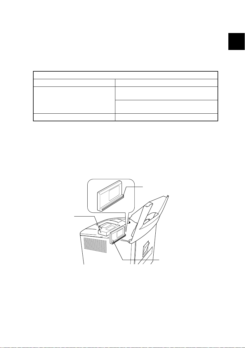
Print head unit
Mirror unit
This figure shows the view inside the Rear Upper Cover with the Imaging Cartridge
removed.
11
Page 20

the USA, Canada
(CDRH Regulation)
• This machine is certified as a Class I Laser product under Radiation Performance Stan-dard
according to the Food, Drug and Cosmetic Act of 1990. Compliance is mandatory for Laser products marketed in the United States and is reported to the Center for Devices and Radiological
Health (CDRH) of the U.S. Food and Drug Administration of the U.S. Department of Health and
Human Services (DHHS). This means that the device does not produce hazardous laser radiation.
• The label shown to page 22 indicates compliance with the CDRH regulations and must be
attached to laser products marketed in the United States.
CAUTION
Use of controls, adjustments or performance of procedures other than those specified in this manual may result in hazardous radiation exposure.
Semiconductor laser
Maximum power of the laser diode 15 mW
Wavelength 775-795 nm
All Areas
CAUTION
Use of controls, adjustments or performance of procedures other than those specified in this manual may result in hazardous radiation exposure.
Semiconductor laser
Maximum power of the laser diode 15 mW
Wavelength 775-795 nm
Denmark
ADVARSEL
Usynlig laserstråling ved åbning, når sikkerhedsafbrydere er ude af funktion.
Undgå udsættelse for stråling. Klasse 1 laser produkt der opfylder IEC60825 sikkerheds kravene.
Halvlederlaser
Laserdiodens højeste styrke 15 mW
bølgelængden 775-795 nm
12
Page 21

Finland, Sweden
LUOKAN 1 LASERLAITE
KLASS 1 LASER APPARAT
VAROITUS!
Laitteen käyttäminen muulla kuin tässä käyttöohjeessa mainitulla tavalla saattaa altistaa käyttäjän
turvallisuusluokan 1 ylittävälle näkymättömälle lasersäteilylle.
Puolijohdelaser
Laserdiodin suurin teho 15 mW
Aallonpituus 775-795 nm
VARNING!
Om apparaten används på annat sätt än i denna bruksanvisning specificerats, kan användaren
utsättas för osynlig laserstrålning, som överskrider gränsen för laserklass 1.
halvledarlaser
Den maximala effekten för laserdioden 15 mW
våglängden 775-795 nm
VARO!
Avattaessa ja suojalukitus ohitettaessa olet alttiina näkymättomälle lasersäteilylle. Älä katso
säteeseen.
VARNING!
Osynlig laserstråining när denna del är öppnad och spärren är urkopplad. Betrakta ej stråien.
1
SAFETY PRECAUTIONS FOR INSPECTION AND SERVICE
Norway
ADVERSEL
Dersom apparatet brukes på annen måte enn spesifisert i denne bruksanvisning, kan brukeren
utsettes för unsynlig laserstrålning, som overskrider grensen for laser klass 1.
Halvleder laser
Maksimal effekt till laserdiode 15 mW
Bølgelengde 775-795 nm
13
Page 22
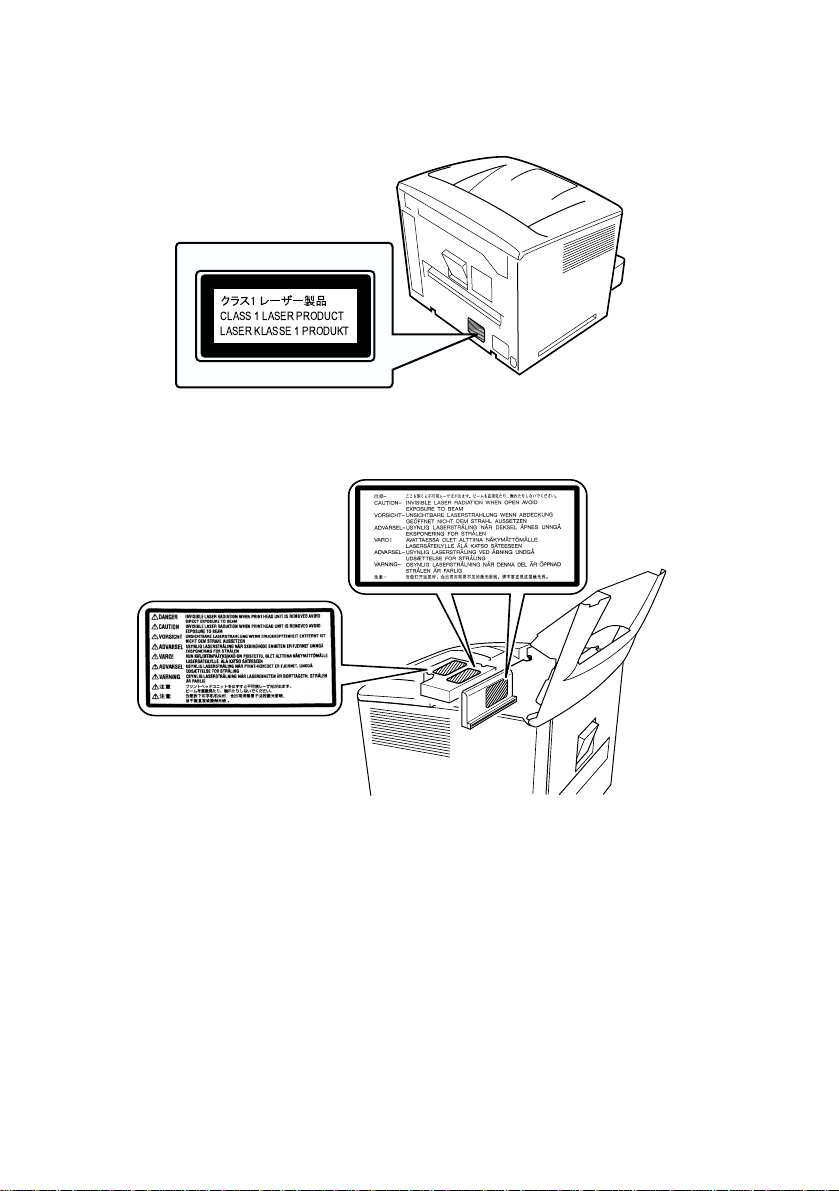
1-7. Laser safety label
• A laser safety label is attached to the outside of the machine as shown below.
CLASS 1 LASER PRODUCT
LASER KLASSE 1 PRODUKT
1-8. Laser caution label
• Three laser caution labels are attached to the inside of the machine as shown below.
1-9. Precautions for handling the equipment
• When laser protective goggles are to be used, select ones with a lens conforming to the above
specifications.
• When a disassembly job needs to be performed in the laser beam path, such as when working
around the print head unit and PC Drum, be sure first to turn the printer OFF.
• If the job requires that the printer be left ON, take off your watch and ring and wear laser protective goggles.
• A highly reflective tool can be dangerous if it is brought into the laser beam path. Use utmost care
when handling tools on the user’s premises.
14
Page 23
2. INSTALLATION
2-1. Installation environment
When installing the printer, please avoid the types of locations listed below, both for safety considerations and to avoid breakdowns.
• Areas with high temperatures or humidity, or with low temperatures and humidity.
• Areas where the temperature and/or humidity fluctuate sharply.
• Places where the printer will be in direct sunlight.
• Areas near a cooler, heater, ventilation opening or in the direct path of wind.
• Areas near oil stoves or other heat-generating equipment.
• Locations with poor ventilation.
• Areas where water is likely to fall on the equipment or electrical leakage is likely.
• Areas where corrosive gases (ammonia gases, etc.) are present.
• Areas where there is a high volume of dust, dirt and vibration.
• Areas where the floor is not sufficiently strong or is not level.
• Areas containing volatile and flammable materials and curtains.
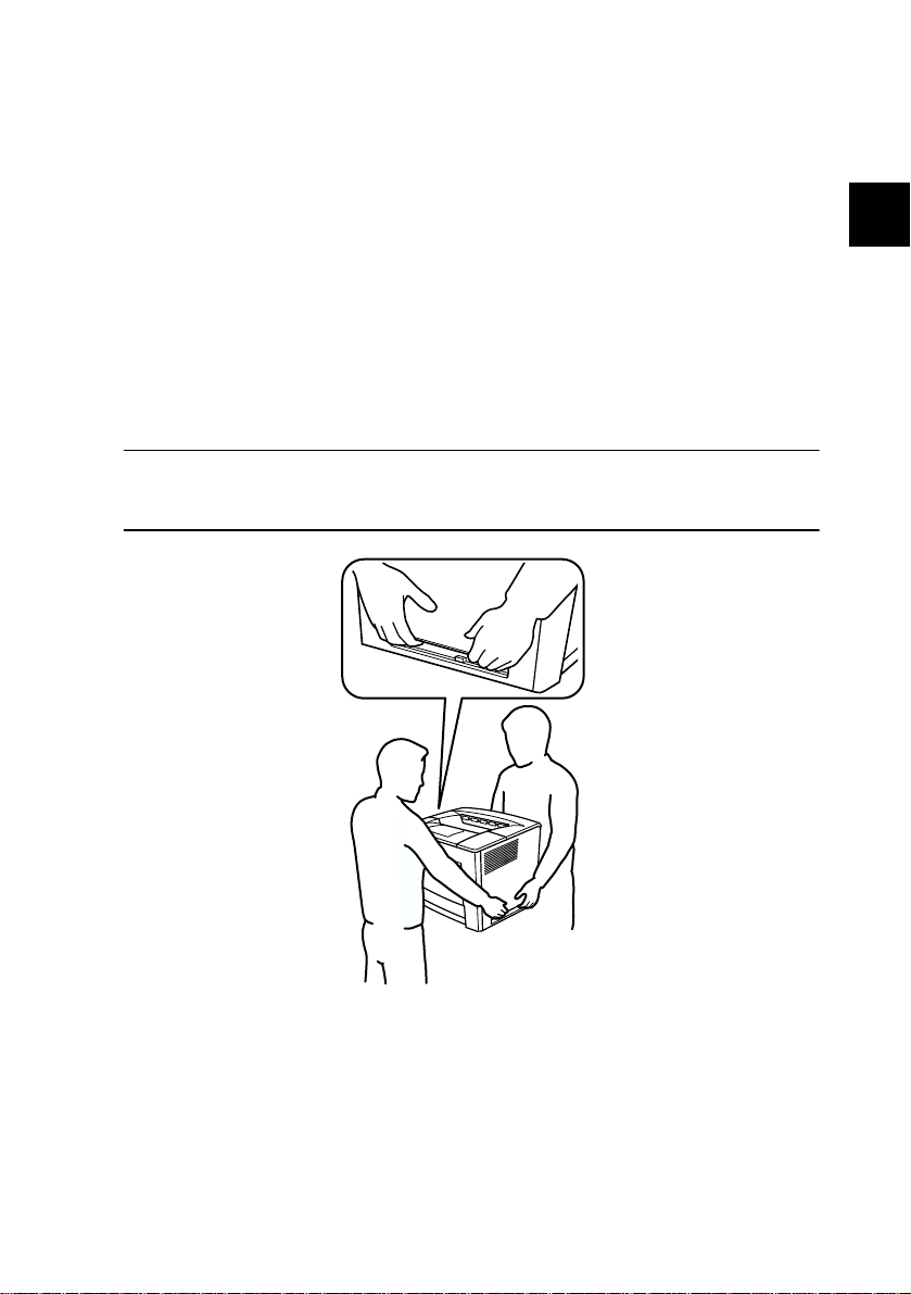
War ni ng
Two people are required to lift the printer. Hold it as shown in the illustration. Be careful not to
strain your back when lifting the printer.
2
INSTALLATION
15
Page 24

2-2. Usage environment
In order to make sure the printer operates properly, please make sure the ambient environment satisfies the following requirements:
Temperature 10-35°C ;50 °F-95 °F
Temperature fluctuation ±10°C or ±18°F per hour or less
Humidity 15-85%RH
Humidity fluctuation ±20% RH per hour or less
2-3. Installing the power supply
• Do not plug the power cord into a power outlet via an extension cord supplying electricity to more
than one unit.
• Do not connect the printer to a power outlet used for other equipment or appliances. More than
one appliance connected to a single outlet could cause a drop or surge in the electrical supply,
resulting in operational problems for the printer.
Voltage fluctuation Specified voltage: ±10%
Frequency fluctuation Specified frequency: ±3Hz
The following items should be checked periodically:
• Make sure the power supply plugs do not feel warm.
• Power supply cords should be free of cracks and scratches.
• Power supply plugs should be firmly plugged into outlets.
16
Page 25
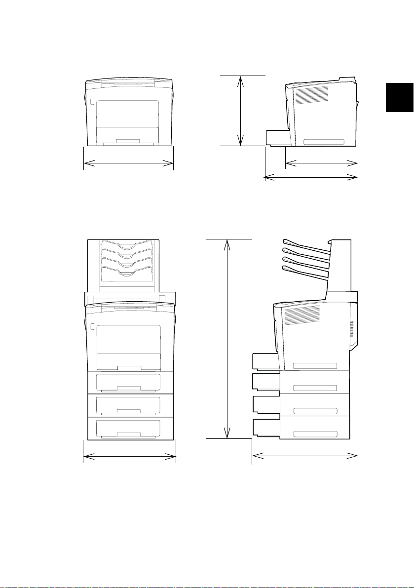
2-4. Space requirements
(1) Standard
423 mm
(16-3/4 in)
539 mm(21-1/4 in)
(2) With options installed
Installed options: Lower feeder unit (3 levels), duplex unit, and 4-bin mailbox.
1,082 mm
(42-1/2 in)
448 mm(17-3/4 in)
566 mm(22-1/4 in)
2
*1
INSTALLATION
539 mm(21-1/4in)
611 mm(24 in)*1
*1: With the media trays installed
17
Page 26

18
Page 27

3. GENERAL INFORMATION
3-1. Specifications
(1) Printer
Typ e
Exposure method
Printing method
Print resolution
Media sizes
Media types
Desktop laser beam printer
Laser diode + Polygon mirror scanning
Electrophotographic
600 dpi (dots/inch)
A5 to A3/Half Letter to Ledger
A3 (297 mm × 420 mm/11.7” x 16.5”)
B4 (257 mm × 364 mm/10.1” x 14.3”)
Folio (210 mm × 330 mm/8.27” x 13”)
A4 (210 mm × 297 mm/8.2” x 11.7”)
JIS-B5 (182 mm × 257 mm/7.2” x 10.1”)
ISO-B5 (176 mm × 250 mm/6.6” x 9.8”)
A5 (148 mm × 210 mm/5.9” x 8.3”)
Ledger (279.4 mm x 432 mm/11” × 17”)
Legal (215.9 mm x 355.6 mm/8.5” × 14”)
G-Legal (215.9 mm x 330.2 mm/8.5 × 13)
Letter (215.9 mm x 279.4 mm/8.5” × 11”)
G-Letter (203.2 mm x 266.7 mm/8” × 10.5”)
Executive (184.15 mm x 266.7 mm/7.25” × 10.5”)
Statement (139.7 mm x 215.9 mm/5.5” × 8.5”)*1,
Japanese Postcard (100 mm x 148 mm/3.9” x 5.8”)
Com 10 (105 mm x 241.3 mm/4.1”x 9.5”)
DL (110 mm x 220 mm/4.3” x 8.7”)
Monarch (98 mm x 191 mm/3.9” x 7.5”)
C5 (162 mm x 229 mm/6.4” x 9”)
C6 (114 mm x 162 mm/4.5” x 6.4”)*
8 Kai (260 mm x 370 mm/10.24” x 14.57”)
16 Kai (185 mm x 260 mm/7.3” x 10.24”)
32 Kai (130 mm x 185 mm/5.12” x 7.3”)
*1
Multipurpose paper tray only
2
Plain paper (60 to 90 g/m
Recycled paper (60 to 90 g/m
Transparencies
Thick paper
*1
Multipurpose paper tray only
*
*
(91 to 163 g/m2; 24 to 43 lbs.), Post cards
; 16 to 24 lbs.)
, Letterheads*, Envelopes*, Label sheets*
*
*
*
*
2
; 16 to 24 lbs.)
*
*
*
*
*
*
3
GENERAL INFORMATION
*
*
*
19
Page 28

First-page print time
Multi-page print
speed
Warm-up time
System speed
Paper feed-in
method
Paper capacity
Paper feed-out
Drum-charging
method
Developing method
Development density
control
Image transfer
method
PC Drum
PC Drum cleaning
method
Paper separation
Fusing method
Single-sided prints
Multipurpose paper tray: Less than 10 seconds *
Universal paper cassette: Less than 10 seconds *
Double-sided prints
Multipurpose paper tray*: Less than 15 seconds *
Universal paper cassette*: Less than 14.5 seconds *
2
*
With A4 or Letter paper.
Single-sided prints
Multipurpose paper tray/A4: 35 ppm
Multipurpose paper tray/Letter: 34.5 ppm
Double-sided prints
Multipurpose paper tray/A4: 26 ppm
Multipurpose paper tray/Letter: 25.6 ppm
Less than 70 seconds*
Recovery time from power save mode: Within 30 seconds*
3
At a room temperature of 23 °C (73.4 °F) and at the rated voltage
*
160.0 mm/s
2-way (maximum 5-way)*
Multipurpose paper tray
Universal paper cassette
Lower feeder unit (optional)*
4
*
Can be expanded to as much as a 5-way system by installing up to three optional Lower
feeder units
Multipurpose paper tray
When using paper with a weight of 16 to 90 lbs (60 - 163 g/m
2
): 200 sheets
Universal paper cassette
2
When using paper with a weight of 16 to 24 lbs (60 - 90 g/m
): 500 sheets
With recommended paper
Face-down
Output tray capacity
When using paper with a weight of 16 to 24 lbs (60 - 90 g/m
2
): 500 sheets
With recommended paper
Needle electrode/scorotron system
Single-element developing system (S MicroToning developing system)
Bias adjustment system
Roller transfer system
OPC (Organic Photoconductor)
Blade system
Mechanical separation by means of paper separator fingers
Heated roller fusing system
20
Page 29

Dimensions
Dimensions
Wei ght
Rated input power
supply voltage
Frequency
Amperage
Power consumption
Acoustic noise
Operating environment
Imaging cartridge
life
Standard configuration
Width: 539 mm(21-1/4 in)
Depth: 448 mm(17-3/4 in) with out the Universal paper cassette
566 mm(22-1/4 in) with the Universal paper cassette installed
Height: 423 mm(16-3/4 in)
With options installed
(with three Lower feeder unit and the duplex unit installed)
Width: 539 mm(21-1/4 in)
Depth: 611 mm(24 in)
Height: 762 mm(30 in)
With options installed
(with three lower feeder units, the duplex unit and the 4-bin mailbox installed)
Width: 539 mm(21-1/4 in)
Depth: 611 mm(24 in)
Height: 1,082 mm(42-1/2 in)
28.0 kg(61-3/4 lbs.) or less*
Imaging cartridge: Approx. 2.5 kg(5-1/2 lbs.)
5
*
Weight of the standard configuration does not include the imaging cartridge.
AC 120 V (operation guaranteed)
AC 230 V (operation guaranteed)
50/60 Hz ±3 Hz
AC 120 V :10A or less
AC 230 V :5A or less
Maximum power consumption: 1,150 W or less*
Average power consumption while printing: 850 W or less
Average power consumption during stand-by: 350 W or less
Average power consumption with the heater off: 40 W or less
Average power consumption in power save mode: 150 W or less
6
At a room temperature of 23 °C(73.4 °F); except when the heater is on
*
During stand-by: 38 dB or less*
While printing: 57 dB or less*
7
Average sound level in four directions with the standard configuration
*
Temperature
10 to 35 °C(50 to 95 °F)
Humidity
15-85%RH
Start-up imaging cartridge:
Average 6,000 or more printer (multi-page printing; black/white ratio=5%)
Replacement imaging cartridge:
Average 15,000 or more prints (multi-page printing; black/white ratio=5%)
3
GENERAL INFORMATION
Standard accessories
(one each )
Options
Power cord
Imaging cartridge
Lower feeder unit (Up to 3 can be installed)
Duplex unit
4-bin Mailbox
21
Page 30

(2) 500-sheet lower feed unit (optional)
Name
Typ e
Installation method
Media types
Media sizes
Paper cassette
capacity
Paper separation
mechanism in the
paper feed-in section
Power source
Drive source
Dimensions
Wei ght
Standard accessories
500-Sheet lower feed unit
Expansion paper feed unit (stacking type)
Secured at the top/bottom
Plain paper 16 to 24 lbs (60 - 90 g/m
Universal
A3 (297 mm × 420 mm/11.7” x 16.5”)
B4 (257 mm × 364 mm/10.1” x 14.3”)
A4 (210 mm × 297 mm/8.2” x 11.7”)
JIS-B5 (182 mm × 257 mm/7.2” x 10.1”)
Ledger (279.4 mm x 432 mm/11” × 17”)
Legal (215.9 mm x 355.6 mm/8.5” × 14”)
Letter (215.9 mm x 279.4 mm/8.5” × 11”)
G-Letter (203.2 mm x 266.7 mm/8” × 10.5”)
G-Legal (215.9 mm x 330.2 mm/8.5 × 13)
When using paper with a weight of 16 to 24 lbs (60 - 90 g/m
Pathway roller paper separation system with torque limiter
Supplied by the printer (DC24 V, DC5 V)
Step motor
Width: 512 mm(20-1/4 in)
Depth: 551 mm(21-3/4 in)
Height: 134 mm(5-1/4 in); 110 mm(4-1/4 in) /unit when stacked
Approx. 9.2 kg(20-1/4 lbs.)
Universal paper cassette
2
), Recycled paper 16 to 24 lbs (60 - 90 g/m2)
2
): 500 sheets
22
Page 31

(3) Duplex unit (optional)
Name
Typ e
Installation method
Media types
Media sizes
Power source
Drive source
Dimensions
Wei ght
Duplex unit
Reverse-circulating sheet-refeeding mechanism
Attached to the back of the printer
Plain paper 16 to 24 lbs (60 - 90 g/m
Recycled paper 16 to 24 lbs (60 - 90 g/m
A3 (297 mm × 420 mm/11.7” x 16.5”)
B4 (257 mm × 364 mm/10.1” x 14.3”)
A4 (210 mm × 297 mm/8.2” x 11.7”)
JIS-B5 (182 mm × 257 mm/7.2” x 10.1”)
A5 (148 mm × 210 mm/5.9” x 8.3”)
Ledger (279.4 mm x 432 mm/11” × 17”)
Legal (215.9 mm x 355.6 mm/8.5” × 14”)
G-Legal (215.9 mm x 330.2 mm/8.5 × 13)
Letter (215.9 mm x 279.4 mm/8.5” × 11”)
G-Letter (203.2 mm x 266.7 mm/8” × 10.5”)
Executive (184.15 mm x 266.7 mm/7.25” × 10.5”)
Statement (139.7 mm x 215.9 mm/5.5” × 8.5”)
*1
Multipurpose paper tray only
Supplied by the printer(DC24 V, DC5 V)
Step motor
Width: 100 mm (4 in)
Depth: 415 mm (16-1/4 in)
Height: 280 mm (11 in)
Approx. 2.0 kg (4-1/2 lbs.)
(4) 4-bin mailbox (optional)
2
)
2
)
3
*1
*
*
GENERAL INFORMATION
Name
Installation method
Number of mailbins
Capacity per mailbin
media types
media sizes
Power source
Dimensions
Wei ght
4-bin mailbox
Attached to the top of the printer
4 mailbins
50 sheets (80 g/m
Plain paper 16 to 24 lbs (60 - 90 g/m
Recycled paper 16 to 24 lbs (60 - 90 g/m
B5 to A3/Letter to Ledger
Supplied by the printer (DC24 V, DC5 V)
Width: 513 mm (20-1/4 in)
Depth: 159 mm (6-1/4 in)
Height: 335 mm (13-1/4 in)
5.5 kg(12 lbs.) or less (with out the Transport unit)
Transport unit: 3.0 kg (6-1/2 lbs.) or less
2
;21-1/4 lbs.)
2
),
2
)
23
Page 32

3-2. Parts identification
9
10
1
2
3
4
5
1 Face-down output tray
2 Power switch (S1)
3 Multipurpose paper tray (MP paper tray)
4 Universal paper cassette (first paper cassette)
5 Lower feeder unit (second through fourth media trays (optional))
6 Control panel
7 Top rear cover release button
8 Transport unit (optional)
9 4-bin mailbox (optional)
10 Imaging cartridge (IC)
8
7
6
24
Page 33

3
1 Duplex unit (optional)
2 Power cord socket
3 Power cord
1
3
GENERAL INFORMATION
2
25
Page 34

3-3. Component diagram
1
I
2
3
G
4
H
F
D
E
B
11
10
9
8
C
7
A
A
A Paper take-up section 1 4-bin mailbox
B Developing section 2 Fusing unit
C Exposure section 3 Duplex unit
D Drum-charging section 4 Image transfer unit
E Image transfer section 5 second through fourth media trays
F Fusing section 6 first paper cassette
G Paper exit section 7 Multipurpose paper tray
H Duplex section 8 Power supply unit
I Sorting section 9 Print head unit
10 Mirror unit
11 Imaging cartridge
6
5
4128G548AA
26
Page 35

3-4. Drive system
(1) Overview of the drive system for the standard configuration
• The rollers in the imaging cartridge are driven by the imaging cartridge drive motor (M2).
• The rollers of the Multipurpose paper tray, first paper cassette, image transfer unit, and fusing unit
are driven by the main motor (M1) via the corresponding gears.
1
2
3
4
5
6
7
8
91011
1 Paper
2 Paper output roller
3 Heat roller
4PC Drum
5 Image transfer roller
6 Registration roller (image transfer section)
7 Main motor (M1)
8 Transport roller
9 Paper take-up roller for the first paper cassette
10 Paper take-up roller for the Multipurpose paper tray
11 Imaging cartridge drive motor (M2)
3
GENERAL INFORMATION
27
Page 36

(2) Diagram of the drive system for the standard configuration
1
2
3
4
5
7
6
1 Paper output roller
2 Heat roller
3PC Drum
4 Transport roller clutch of the image transfer section
5 Transport roller of the paper feed-in section
6 Paper take-up roller for the first paper cassette
7 Main motor (M1)
8 Paper take-up roller for the multipurpose paper tray
9 Imaging cartridge drive motor (M2)
28
8
9
Page 37

(3) Overview of the drive system when options are installed
• The second through fourth Lower feeder units are equipped with motors for transporting paper
(paper take-up motor M1). When transporting paper from an optional paper cassette, the paper
take-up roller and transport roller of the optional paper cassette are driven by the paper take-up
motor installed in the paper cassette unit. In addition, when printing from a lower optional paper
cassette, the paper take-up motors of the upper optional paper cassette units also drive their transport rollers. For example, when printing from the fourth optional paper cassette, the paper take-up
motors of the second and third lower feeder units also drive their transport rollers.
• By installing the optional duplex unit, the drive source for the paper output roller in the printer’s
fusing unit is switched from the main motor (M1) of the printer to the switchback motor (M2) of
the duplex unit.
• The transport rollers and the feed-back roller of the duplex unit are driven by the transport motor
(M1) of the duplex unit.
• The bin output roller and the transport rollers of the 4-bin mailbox are driven by the transport
motor (M1) of the 4-bin mailbox.
3
10
11
1
2
3
4
5
6
7
8
9
1 Transport motor of the 4-bin mailbox
(M1)
2 Bin output roller
3 Transport roller
4 Switchback motor of the duplex unit (M2)
5 Upper transport roller
6 Lower transport roller
7 Transport motor of the duplex unit (M1)
8 Feed-back roller
9 Transport roller
10 Paper take-up roller
11 Paper take-up motor (M1) of the lower
feed unit
GENERAL INFORMATION
29
Page 38

3-5. Electrical components layout
(1) Printer
PWB-H
TS1
TF1
PWB-G
S1
H1
R2
PC5
PC3
M3
TH1
R1
M1
CL2
CL1 Transport roller clutch of the image transfer section
CL2 Paper take-up clutch for the first paper cassette
H1 Heater
HS1 Humidity sensor
HV1 High voltage unit
M1 Main motor
M2 Imaging cartridge drive motor
M3 Fusing fan motor
M4 Power supply unit fan motor
M5 Polygon motor
M6 Ozone fan motor
PC1 Paper sensor of the image transfer section
PC3 Paper output sensor
PC4 Paper empty sensor for the multipurpose paper tray
CL1
M2
S3
PWB-D
PC7
PC1
SL1
HV1
S4
PC4
M6
M5
PU1
S2
PWB-O
M4
PWB-A
TH2
HS1
30
Page 39

PC5 Paper near-empty sensor for the multipurpose paper tray
PC6 Paper empty sensor for the first paper cassette
PC7 Paper near-empty sensor for the first paper cassette
PU1 Power supply board
PWB-A Main control board
PWB-D New-imaging-cartridge detection board
PWB-G Toner empty detection board
PWB-H Paper full detection board
PWB-O Control panel board
R1 Resistor 1
R2 Resistor 2
S1 Power switch
S2 Interlock switch 1
S3 Interlock switch 2
S4 Paper size detection switch for the first paper cassette
SL1 Paper take-up solenoid for the multipurpose paper tray
TF1 Thermal fuse
TH1 Thermistor 1
TH2 Thermistor 2
TS1 Thermostat
3
GENERAL INFORMATION
31
Page 40

(2) Lower feed unit (optional)
M1
CL1
PC3
S1
CL1 Paper take-up clutch
M1 Paper take-up motor
PC1 Paper sensor
PC2 Paper empty sensor
PC3 Paper near-empty sensor
PWB-A Control board
S1 Paper size detection switch
(3) Duplex unit (optional)
PC1
PC2
PWB-A
M2
PC2
PWB-A
M1
M1 Transport motor
M2 Switchback motor
PC1 Duplex cover switch
PC2 Duplex unit paper sensor (on PWB-A)
PWB-A Control board of the duplex unit
PC1
32
Page 41

(4) 4-bin mailbox (optional)
PC8
PC11
M1
PWB-A
SL4
SL3
SL2
SL1
PC12
M1 Transport motor
PC1~4 Bin empty sensor 1~ 4
PC5~PC8 Bin full sensor 1~ 4
PC9 Lower transport sensor
PC10 Upper transport sensor
PC11 Cover sensor
PC12 Set sensor
PWB-A Control board
SL1 Entrance guide switching solenoid
SL2~SL4 Bin entrance switching solenoid
PC4
PC7
PC1
PC3
PC10
3
PC6
PC5
PC2
PC9
GENERAL INFORMATION
33
Page 42

3-6. Electrical components functions
(1) Printer
Symbol Name Function
CL1 Transport roller clutch of the
image transfer section
CL2 Paper take-up clutch for the first
paper cassette
H1 Heater Heats the heat roller.
HS1 Humidity sensor Detects the humidity within the machine, and sends that data to the
HV1 High voltage unit Steps up the voltage of the direct current (DC) output from the
M1 Main motor Provides the driving force for each part of the printer; main drive
M2 Imaging cartridge drive motor Drives the imaging cartridge.
M3 Fusing fan motor Cools the fusing section and the inside of the machine. In addition,
M4 Power supply unit fan motor Absorbs outside air and cools the power supply section and the
M5 Polygon motor (within the print
head unit)
M6 Ozone fan motor Expels air from inside the machine to the outside. In addition, the
PC1 Paper sensor of the image trans-
fer section
PC3 Paper output sensor Detects whether paper has been fed out by the transport roller.
PC4 Paper empty sensor for the multi-
purpose paper tray
PC5 Paper near-empty sensor for the
multipurpose paper tray
PC6 Paper empty sensor for the first
paper cassette
PC7 Paper near-empty sensor for the
first paper cassette
PU1 Power supply board Converts the power supply voltage from alternating current (AC)
PWB-A Main control board Controls all printer operations.
PWB-D New-imaging-cartridge detec-
tion board
PWB-G Toner empty detection board Detects whether the toner in the imaging cartridge is empty.
PWB-H Paper full detection boad Detects the amount of paper that has been fed into the face-down
Transmits the driving force from the main motor to the transport
roller of the image transfer section.
Transmits the driving force from the main motor to the paper takeup roller of the first paper cassette.
main control board.
power supply board to a high voltage, and supplies it to the drumcharging section, the image transfer section and the developing
section.
source.
the paper being printed is drawn toward the image transfer unit.
(suction effect)
print head unit section. In addition, sends ozone, generated within
the machine, to the ozone fan motor (M6).
A regular hexahedron polygon mirror rotates at a high speed, causing the laser to irradiate the surface of the PC drum in the main
scanning direction.
ozone filter attached to the fan removes any ozone generated
within the machine.
Detects whether paper has been loaded and whether the paper has
been transported.
Detects whether there is no paper in the multipurpose paper tray.
Detects whether there is almost no paper in the multipurpose paper
tray.
Detects whether there is no paper in the first paper cassette.
Detects whether there is almost no paper in the first paper cassette.
to direct current (DC) and outputs it. The alternating current is supplied by the heater (H1).
Detects the record information for the imaging cartridge.
output tray. PS3 is mounted on board.
34
Page 43

Symbol Name Function
PWB-O Control panel boad Operates the printer through the operation keys and indicates the
R1 Resistors Prevents poor image transfer, and prevents noise from being generR2
S1 Power switch Switches on and off the power.
S2 Interlock switch 1 Detects whether the top rear cover is open or closed, and interrupts
S3 Interlock switch 2 Interrupts the alternating current (AC) output power to the heater
S4 Paper size detection switch for
the first paper cassette
SL1 Paper take-up solenoid for the
multipurpose paper tray
TF1 Thermal fuse Interrupts the electric conduction to the heater (H1) when there is
TH1 Thermistor 1 Detects the temperature on the surface of the heat roller, and sends
TH2 Thermistor 2 Detects the atmospheric temperature within the machine, and
status of the printer through the indicator and message display.
ated.
the DC 24 V direct current (DC) output power if the cover is open.
(H1) if the top rear cover is open.
Detects the size of the paper loaded into the first paper cassette.
Transmits the driving force from the main motor to the paper takeup roller for the multipurpose paper tray.
an abnormally high temperature in the fusing section.
that data to the main control board.
changes developing bias DC voltage to match
TS1 Thermostat Controls the temperature of the heat roller surface. If the tempera-
ture exceeds 450 °C, then the circuit conducting electricity to the
heater (H1), the DC 24 V circuit and the relays are forcibly cut.
(2) Lower feed unit (optional)
Symbol Name Function
CL1 Paper take-up clutch Transmits the driving force from the paper take-up motor to the
M1 Paper take-up motor Drives the paper take-up roller and the transport roller.
PC1 Paper sensor Detects whether paper has been loaded and whether the paper has
PC2 Paper empty sensor Detects whether there is no paper in the cassette.
PC3 Paper near-empty sensor Detects whether there is almost no paper in the cassette.
PWB-A Control board Receives control signals and power from the printer’s main control
S1 Paper size detection switch Detects the size of the paper loaded into the cassette.
paper take-up roller of the lower feed unit.
been transported.
board PWB-A, and sends them to the electrical components within
the lower feed unit.
3
GENERAL INFORMATION
35
Page 44

(3) Duplex unit (optional)
Symbol Name Function
M1 Transport motor Drives the feed-back roller and the transport roller.
M2 Switchback motor Rotates the paper output roller in the printer’s fusing unit in both
PC1 Duplex cover switch Detects whether the duplex cover is open or closed, and stops the
PC2 Duplex unit paper sensor Detects whether paper has been fed into the duplex unit.
PWB-A Control board of the duplex unit Receives control signals and power from the printer’s main control
directions, and feeds the paper back into the duplex unit.
functions of the duplex unit if its cover is open.
board PWB-A, and sends them to the electrical components within
the duplex unit.
(4) 4-bin mailbox (optional)
Symbol Name Function
M1 Transport motor Drives the bin output roller and the transport roller of the 4-bin
PC1 Bin empty sensor 1 Detects whether paper has been fed into the bin.
PC2 Bin empty sensor 2
PC3 Bin empty sensor 3
PC4 Bin empty sensor 4
PC5 Bin full sensor 1 Detects whether the paper fed into the mailbin has reached the
PC6 Bin full sensor 2
PC7 Bin full sensor 3
PC8 Bin full sensor 4
PC9 Lower transport sensor Detects whether paper has been fed from the printer.
PC10 Upper transport sensor Detects whether paper has been transported to a mailbin.
PC11 Cover sensor Detects whether the 4-bin mailbox cover is open or closed, and
PC12 Set sensor Detects whether the 4-bin mailbox unit is open or closed, and
PWB-A Control board of the 4-bin mail-
box
SL1 Entrance guide switching sole-
noid
SL2 Bin entra nce switching solenoid 1Moves the bin entrance switch, and directs the transported paper
SL3 Bin entra nce switching solenoid
2
SL4 Bin entra nce switching solenoid
3
mailbox.
maximum capacity.
stops the functions of the 4-bin mailbox if its cover is open.
stops the functions of the 4-bin mailbox if it is slid open.
Receives control signals and power from the printer’s main con-
trol board PWB-A, and sends them to the electrical components
within the 4-bin mailbox.
Moves the entrance guide, and directs the paper fed from the
printer into the 4-bin mailbox.
to each mailbin.
36
Page 45

(5) PWB-A (main control board)
PJ11 PJ12 PJ13 PJ8 PJ9
PJ7
PJ15
PJ5
PJ21
PJ16
PJ6
PJ14
PJ10
F1
PJ17
VR1
PJ1
3
PJ22
PJ4
PJ23
PJ2 PJ3
F1 Fuse (rated: 15 A, 250 V)
PJ1 To the printer controller
PJ2 To the fusing section and the transport section
PJ3 To the relay section for the multipurpose paper tray
PJ4 To the lower feed unit
PJ5 To the new-imaging-cartridge detection board
PJ6 To the laser diode
PJ7 To the high voltage unit
PJ8 To the polygon motor
PJ9 To the main motor and the imaging cartridge drive motor
PJ10 To power supply section 1
PJ11 To power supply section 2
PJ12 To power supply section 3
PJ13 To the ozone fan motor
PJ14 To the left side of the printer
PJ15 To the paper size detection board for the multipurpose paper tray
PJ16 To the duplex unit
PJ17 To the 4-bin mailbox
PJ21 To the paper full detection board
PJ22 To the control panel board
PJ23 To the humidity sensor
VR1 Dial for adjusting the image registration margin (refer to chapter 6.)
GENERAL INFORMATION
37
Page 46

(6) PWB-D (new-imaging-cartridge detection board)
PJ1
PJ1 To the main control board
(7) PU1 (power supply board )
VR1
AC_N
CN1
AC_L To the interlock switch 1 section primary
AC_N To the interlock switch 1 section primary
CN1 To the power switch section
CN4 To the interlock switch 1 section secondary
CN5 To the main control board
CN6 To the main control board
CN7 To the main control board
F1 Fuse (rated: 10 A, 125 V)
F2 Fuse (rated: 15 A, 250 V)
VR1 Factory adjustments (do not adjust.)
VR131 Factory adjustments (do not adjust.)
VR151 Factory adjustments (do not adjust.)
VR53 Factory adjustments (do not adjust.)
AC_L
F2
F1
VR53
VR151
VR131
CN6
CN5
CN7
CN4
38
Page 47

(8) HV1 (high voltage unit )
E
G
BL
B
B To the bias and discharge seal
BL To the paper take-up roller, blade 1 and blade 2
C(PJ1-CHV) To the drum-charging section
CN1 To the main control board
E To the discharge needle
G To the grid mesh
T(PJ1-THV) To the image transfer section
VR101 Factory adjustments (do not adjust.)
VR201 Factory adjustments (do not adjust.)
VR301 Factory adjustments (do not adjust.)
VR302 Factory adjustments (do not adjust.)
VR401 Factory adjustments (do not adjust.)
VR402 Factory adjustments (do not adjust.)
VR403 Factory adjustments (do not adjust.)
VR501 Factory adjustments (do not adjust.)
C
T
VR101
VR201
CN1
VR403
VR402
VR401
VR302
VR301
3
VR501
GENERAL INFORMATION
39
Page 48

(9) PWB-G (toner-empty detection board)
PJ1 To the main control board
VR1 Dial for factory adjustments (do not adjust.)
(10) PWB-H (paper full detection board)
PJ1
VR1
PJ1 To the main control board
PS3 Paper full detection sensor
(11) PWB-O (control panel board)
LCD1 Message display
LED1 to LED3 Message indicators
PJ2 To the main control board(printer)
SW1 to SW8 Control keys
PS3
LCD1
LED3
SW4 SW3 SW2 SW1
SW8 SW7 SW6 SW5
LED2 LED1
PJ1
PJ2
40
Page 49

(12) PWB-A (control board of the lower feed unit)
PJ1
PJ1 To the main control board
PJ2 To the unit below
PJ3 To the paper near-empty sensor and the paper size detection switch
PJ4 To the paper jam detection sensor and the paper empty sensor
PJ5 To the paper take-up motor and the paper take-up clutch
(13) PWB-A (DUP) (control board of the duplex unit)
PJ5
PJ2
PJ3
PJ2
PJ1
PJ4
PC1
PJ4
3
GENERAL INFORMATION
PJ3
PC1 To the duplex unit paper sensor
PJ1 To the main control board
PJ2 To the transport motor
PJ3 To the switchback motor
PJ4 To the duplex cover switch
41
Page 50

(14) PWB-A (control board of the 4-bin mailbox)
CN106 CN102 CN107
CN103
CN101
CN108
CN104
CN109
CN110 CN105CN100 FU100
CN101 To the cover sensor, bin empty sensor 4, and bin full sensor 4
CN100 To the main control board
CN102 To bin empty sensor 3 and bin full sensor 3
CN103 To the upper transport sensor, bin empty sensor 2, and bin full sensor 2
CN104 To bin empty sensor 1 and bin full sensor 1
CN105 To the lower transport sensor
CN106 To the transport motor
CN107 To bin entrance switching solenoid 3
CN108 To bin entrance switching solenoid 2
CN109 To bin entrance switching solenoid 1
CN110 To the entrance guide switching solenoid
FU100 Fuse (rated: 1 A, 125 V)
42
Page 51

3-7. Video interface
(1) Overview
• The video interface consists of 12 signal wires and the power supply source, as shown below.
• The signal wires include those for image data signals for transmitting images, synchronous signals, signals for observing the status of the power supply, serial transmission signals for obtaining
a detailed status of the printer, and reset signals.
.
/ CPRDY
/ CTBSY
/ CMD
/ SRCLK
/ RESET
3
Controller
/ EPRDY
/ PRRDY
/ TOD
/ ETBSY
/ STS
/ HSYNC
/ VIDEO
Main Control Boad
PWB-A
Print Head Unit
Laser Control Boad
PWB-B
+5V
+3.3V
GND
Power Unit
PU1
GENERAL INFORMATION
43
Page 52

(2) Signal descriptions
There are 12 interface signals, which are divided into 5 categories according to their function.
No. Signal Name Code Function Category
1 /Controller
power ready
2 /Engine power
ready
3 /Printer ready /PRRDY This signal indicates that the printer is ready to
4 /Top of data /TOD This is the synchronous signal of the vertical
5 /Horizontal syn-
chronous
6 /Video /VIDEO This is the image data signal.
7 /Controller sta-
tus busy
8 /Engine status
busy
9 /Command /CMD This signal is used when transmitting 8-bit
10 /Status /STS This signal is used when the main control board
11 /Serial clock /SRCLK
12 /Reset /RESET This signal resets the printer hardware.
/CPRDY This signal indicates that the controller is ready
to send signals to and receive them from the
main control board (PWB-A).
/EPRDY This signal indicates that the main control board
(PWB-A) is ready to send signals to and receive
them from the controller.
print.
scanning direction (sub-scanning direction) for
beginning printing of one page.
/HSYNC This is the synchronous signal of the horizontal
scanning direction (main scanning direction) for
beginning printing of each line.
/CTBSY This signal indicates that the controller is send-
ing commands to the main control board (PWBA).
/ETBSY This signal indicates that the main control board
(PWB-A) is using the /STS signal, and sending
the status to the controller.
serial information (commands) to the main control board (PWB-A).
(PWB-A) sends 8-bit serial information (commands) to the controller.
This synchronous clock signal is used when the
controller sends commands to the main control
board (PWB-A), and when the main control
board (PWB-A) sends the status to the controller.
Signals for activating
the video interface.
Signals that indicate
the printer status.
Signals for printing
images.
Signals for serial
transmission between
the controller and the
main control board.
44
Page 53

3-8. Timing chart
(1) Pre-process sequence
• The processing devices around the PC drum are started up, and the surface of the PC drum is
charged with an exposable uniform electric potential.
• When the pre-process sequence is finished, the operation continues with the print (print interval)
sequence.
.
Polygon motor (M5)
Paper sensor of the image
transfer section (PC1)
Transport roller
Imaging cartridge
drive motor (M2)
Exposure
Drum charging, Bias and
discharge seal - (DC) output
Bias and discharge seal (DC) output voltage setting
Bias and discharge seal (AC) output
Image transfer
OFF
OFF
OFF
OFF
OFF
OFF
OFF
OFF
Execution condition: print ON
Start condition: When the process start timing is reached when receiving a print
Pre-process sequence
1
ON
2
ON
APC
2
ON
2
-
4
ON
7
ON
4
ON
5
ON
+
3
8
TOD output permission
6
3
GENERAL INFORMATION
1: Polygon motor ON
2: Imaging cartridge drive motor ON, charge, image transfer, grid, discharge; Remote of
sheet and discharge needle ON
3: Image transfer voltageoutput
4: Developing bias DC remote ON, according to the detected temperature
5: Developing bias AC remote ON
6: TOD output permitted
7: Transport roller ON
8: Switch the image transfer current
45
Page 54

(2) Print (print interval) sequence
• In order to suppress image quality problems from occurring, the process control is switched when
printing and during the print interval.
Print(print interval)sequence
Paper sensor of the
image transfer section (PC1)
Transport roller
B (DC) output voltage setting
B (AC) output
Image transfer
ON
ON
ON
ON
OFF
Print
Print interval
1
OFF
OFF
Print value
Print interval
Print
4
ON
ON
OFF
ON
Post-process sequence start judgment
Post-process sequence start judgment
OFF
Print value
1: Begin mode switching from print to print interval
2: Image transfer current (print interval) ON
3: Post-process sequence shift judgment
3: Change developing bias DC voltage to match <thermistor 2> and <image density
setting>
4: Change image transfer current to match paper size, media and print area
(3) Post-process sequence
• Before stopping the processing devices around the PC drum, the PC drum and image transfer
roller is cleaned.
• The processing devices around the PC drum are stopped, and the print operation is finished.
Post-process sequence
Imaging cartridge
drive motor
C, B (DC) output
B (DC) output voltage setting
B (AC) output
Image transfer
ON
ON
ON
ON
OFF
OFF
OFF
Condition for starting post-process: When the fed paper has passed through all of the image transfer
section, and when a paper feed cancel request has been received
Condition for deferring post-process: When the first sheet of paper is waiting to be fed after the process has started
1: Image transfer (-) output, developing bias DC remote OFF, and developing bias
AC remote OFF
2: Imaging cartridge drive motor OFF, Charge, image transfer, grid, discharge; Remote of
sheet and discharge needle OFF
46
Page 55

4. MECHANICAL/ELECTRICAL
4-1. Paper path
(1) Standard configuration
• Paper can be fed into the printer either from the multipurpose tray (paper capacity: 200 sheets) or
the universal paper cassette unit (paper capacity: 500 sheets).
• The paper fed by the paper take-up roller is transported to the transport roller of the image transfer
section
fed out into the face-down output tray.
1
the image transfer roller
→
the fusing roller
→
the paper output roller, then finally
→
15
14
4
2
G
3
4
5
F
D
C
6
7
8
9
10
A Paper take-up section 1 Paper output roller
B Developing section 2 Paper output sensor (PC3)
C Exposure section 3 Heat roller
D Drum-charging section 4 PC Drum
E Image transfer section 5 Image transfer roller
F Fusing section 6 Transport roller (image transfer section)
G Paper exit section 7 Paper sensor of the image transfer section (PC1)
E
B
A
8 Transport roller (first paper cassette)
9 Paper take-up roller for the first paper cassette
10 Paper near-empty sensor for the first paper cassette (PC7)
11 Paper near-empty sensor for the multipurpose paper tray (PC5)
13
12
11
MECHANICAL/ELECTRICAL
47
Page 56

(continued from previous page)
12 Paper empty sensor for the first paper cassette (PC6)
13 Paper take-up roller for the multipurpose paper tray
14 Face-down output tray
15 Paper full detection board (PWB-H) (PS3 is mounted on board)
48
Page 57

(2) With options installed
• By installing up to three optional lower feeder units (paper capacity: 500 sheets), the printer can
be expanded to have a maximum of 5 paper sources.
• Double-sided printing is possible if the optional duplex unit is installed.
• The printouts can be sorted by installing the optional 4-bin mailbox.
• When double-sided printing is selected, the paper is transported to the transport roller of the
image transfer section → the image transfer roller → the fusing roller → the paper output roller →
the upper transport roller of the duplex unit → the lower transport roller of the duplex unit → the
feed-back roller of the duplex unit → the transport roller of the image transfer section → the
image transfer roller → the fusing roller → the paper output roller, then finally fed out into the
face-down output tray.
• If sorted printing is selected, the paper is transported to the transport roller of the image transfer
section → the image transfer roller → the fusing roller → the lower transport roller of the 4-bin
mailbox → the upper transport roller of the 4-bin mailbox → the paper output roller, then finally
fed out into the mailbin trays.
4
10
11
12
13
1
I
H Duplex section
I Sorting section
2
3
4
H
5
6
1 Bin output roller
2 Upper transport sensor (PC10)
3 Lower transport sensor (PC9)
4 Lower transport roller
5 Upper transport roller
6 Duplex unit paper sensor (PC2)
7 Lower transport roller
8 Feed-back roller
9 Paper empty sensor (PC2)
10 Transport roller
11 Paper take-up roller
MECHANICAL/ELECTRICAL
7
8
9
49
Page 58

4-2. Paper take-up section
(1) Multipurpose paper tray: paper take-up mechanisms & process
11
1
2
3
4
5
6
1 Paper take-up roller 7 Paper-separating pad
2 Paper 8 Paper empty/paper near-empty actuator
3 Paper take-up roller drive shaft 9 Paper-lifting plate
4 Unit drive gear 10 Cam
5 Paper take-up roller drive gear 11 Transport roller
6 Paper take-up solenoid (SL1)
1. When the paper take-up solenoid (SL1) is activated, the solenoid locking catch that secures the
paper take-up roller drive gear, attached to the paper take-up roller shaft, in a fixed position is
released by the cam of the paper take-up roller drive gear.
2. The paper take-up roller drive gear is rotated by the spring attached to it, and linked to the unit
drive gear.
10
9
8
7
1
2
1 Paper take-up roller drive gear 3 Unit drive gear
2 Paper take-up solenoid (SL1) 4 Spring
50
4
3
Page 59

3. The driving force from the main motor (M1) is transmitted from the unit drive gear to rotate the
paper take-up roller shaft.
1
1 Cam 3 Paper-lifting plate
2 Paper take-up roller 4 Multipurpose paper tray
4. The cam attached to the paper take-up roller shaft rotates, allowing the paper-lifting plate to be
raised by the spring.
5. The paper take-up roller, attached to the paper take-up roller shaft, rotates once, the pick-up surface of the paper take-up roller contacts the paper, and then the paper is fed to the transport
roller.
A fixed separating pad is used to separate the paper, preventing other sheets of paper from being
fed together with the first.
6. The transport roller attached to the paper take-up roller shaft feeds the paper into the printer.
7. When the paper take-up roller drive gear is rotated once, the driving force from the main motor
is released by the missing teeth, causing the rotation to stop.
8. The locking catch of the paper take-up solenoid (SL1) secures the paper take-up roller drive gear
in place.
2
34
4
MECHANICAL/ELECTRICAL
51
Page 60

(2) Multipurpose paper tray: paper feed retry control
• If the paper feed operation began, but the paper take-up roller was not able to pick up the paper,
instead of concluding that a paper jam occurred, the paper feed operation is performed again
(paper feed retry function).
• If the second attempt of the paper feed operation (first paper feed retry) fails, the paper feed operation is performed one more time.
• If no paper was fed and the paper sensor of the image transfer section (PC1) could not detect the
leading edge of the paper during the third attempt of the paper feed operation (second paper feed
retry), the printer concludes that a paper jam occurred.
• The paper feed operation is attempted three times, including the initial attempt.
Paper feed
Initial paper
retries
feed operation
52
Page 61

(3) Multipurpose paper tray: paper empty detection mechanism
• The multipurpose paper tray is equipped with a paper empty sensor (PC4), which monitors the
amount of paper remaining in the multipurpose tray.
• If paper is present in the tray, the actuator is pressed down by the paper. (The actuator is attached
to the same shaft as the paper near-empty sensor.)
1
2
1 Paper empty actuator (toward the back) 2 Paper near-empty actuator (toward the front)
• Since the actuator does not interrupt the sensor light, the sensor light passes through, enabling the
sensor to determine that paper is present in the multipurpose paper tray.
• If there is no paper, the actuator is raised by the spring, blocking the sensor light. If the sensor
light is interrupted for 0.5 seconds or more, the sensor determines that there is no paper.
4
MECHANICAL/ELECTRICAL
1 Paper (when full)
2 Actuator (paper empty status)
3 Actuator (paper full status)
4 Paper empty sensor (PC4)
1 32 4
53
Page 62

(4) Multipurpose paper tray: paper near-empty detection mechanism
• The multipurpose paper tray is equipped with a paper near-empty sensor (PC5), which monitors
the amount of paper remaining while printing.
• If there is a sufficient amount of paper remaining, the actuator is pressed down by the paper. (The
actuator is the same as that for the paper empty sensor.)
• Since the actuator does not interrupt the sensor light, the sensor light passes through, enabling the
sensor to determine that a sufficient amount of paper remains.
• If there is not much paper left, the actuator is raised by the spring, blocking the sensor light. When
the sensor light is interrupted, the sensor determines that there is little paper remaining (nearempty).
• The sensor detects a near-empty state when approximately 50 sheets of paper (normal paper,
2
) remain. However, the amount of paper detected fluctuates depending on the weight of
64 g/m
the paper.
Note
Since the paper near-empty condition is only monitored while printing, the actuator blocking the
sensor light during stand-by is not considered a paper near-empty condition.
1
1 Paper (when near-empty)
2 Actuator (paper full status)
3 Actuator (paper near-empty status)
4 Paper near-empty sensor (PC5)
23
54
4
Page 63

(5) Universal paper cassette (first through fourth paper cassettes): paper take-up mecha-
nism
• When the paper cassette is inserted into the printer, the lock for the paper-lifting plate is released,
and the paper-lifting plate is raised by the spring.
• When the paper take-up clutch for the first paper cassette is activated, the driving force from the
main motor is transmitted to the drive gear attached to the paper take-up roller shaft, and the paper
take-up roller shaft is rotated.
• The paper take-up roller attached to the paper take-up roller shaft is rotated, feeding the paper into
the printer. A paper-separating roller is used to separate the paper, preventing other sheets of paper
from being fed together with the first.
• When the paper cassette is pulled out of the printer, the paper-lifting plate is lowered by the cassette-mounting rail, then locked into place.
123
4
4
1 Paper-separating roller
2 Paper take-up roller
3 Paper-lifting plate
4 Spring
(6) Universal paper cassette (first paper cassette): paper feed retry control
• If the paper feed operation has already begun, but the paper take-up roller was not able to pick up
the paper, instead of concluding that a paper misfeed has occurred, the paper feed operation is performed again (paper feed retry function).
• If no paper was fed and the paper sensor of the image transfer section (PC1) could not detect the
leading edge of the paper during the second attempt of the paper feed operation (paper feed retry),
the printer concludes that a paper misfeed has occurred.
• The paper feed operation is attempted twice, including the initial attempt.
Initial paper
feed operation
Paper feed
retries
55
MECHANICAL/ELECTRICAL
Page 64

(7) Lower feed unit (second through fourth paper cassettes): paper feed retry control
• If the paper feed operation has already begun, but the paper take-up roller was not able to pick up
the paper, instead of concluding that a paper misfeed has occurred, the paper feed operation is performed again (paper feed retry function).
• If the second attempt of the paper feed operation (first paper feed retry) fails, the paper feed operation is performed one more time.
• If no paper was fed and the paper sensor of the image transfer section (PC1) could not detect the
leading edge of the paper during the third attempt of the paper feed operation (second paper feed
retry), the printer concludes that a paper misfeed has occurred.
• The paper feed operation is attempted three times, including the initial attempt.
Initial paper
feed operation
Paper feed retries
56
Page 65

(8) Universal paper cassette (first paper cassette): paper empty detection mechanism
• The paper empty sensor for the first paper cassette (PC6) is installed below the multipurpose tray
to monitor the amount of paper remaining in the universal paper cassette (first paper cassette).
• If paper is present in the cassette, light from the emitter of the paper empty sensor for the first
paper cassette (PC6) reflects off the paper. If the sensor receiver picks up the reflected light, the
sensor determines that paper is present in the cassette.
1
A
B
A Sensor light (emitted light) 1 Paper empty sensor for the first paper cassette (PC6)
B Sensor light (reflected light) 2 Paper
3 Paper-lifting plate (paper full status)
• If there is no paper in the cassette, the light from the paper empty sensor of the first paper cassette
is absorbed by the light-absorbing material affixed to the bottom of the cassette, resulting in sensor not detecting reflected light. If the sensor light is interrupted for 0.5 seconds or more, the sensor determines that there is no paper.
123
A
2
3
4
MECHANICAL/ELECTRICAL
1 Paper empty sensor for the first paper cassette (PC6)
2 Sensor light pass-through window
3 Paper-lifting plate (paper empty status)
4 Light-absorbing material
57
4
Page 66

(9) Universal paper cassette (second through fourth paper cassettes): paper empty detection
mechanism
• The paper empty detection mechanism for monitoring the amount of paper remaining in the second through fourth optional paper cassettes is the same as that for the first paper cassette.
• The difference from the first paper cassette is the mounting location of the paper empty sensor
(PC2). In the paper empty detection mechanism for the first paper cassette, the paper empty sensor is mounted below the multipurpose tray; however, in the other paper cassettes, it is mounted
on the top of the expansion paper cassette unit.
1 Paper empty sensor (PC2))
2 Paper near-empty sensor (PC3)
1
2
58
Page 67

(10) Universal paper cassette (first through fourth paper cassettes): paper near-empty detec-
tion mechanism
• A paper near-empty sensor (PC7) (see page 48, item #10) is installed in the mounting section of
the first paper cassette in order to monitor the amount of paper remaining in the first paper cassette. In addition, the paper near-empty sensor (PC3) is installed in the top of the lower feed unit
to monitor the amount of paper remaining in the second through fourth expansion cassettes.
• When paper is present in the cassette, the paper-lifting plate is lowered so that the actuator is not
raised. Since the actuator does not interrupt the sensor light, the sensor light passes through,
enabling the sensor to determine that paper is present.
• If there is not much paper left, the paper-lifting plate is raised, lifting the actuator, which blocks
the sensor light. If the sensor light is interrupted for 0.5 seconds or more, the sensor determines
that there is little paper remaining.
2
1
1 Paper near-empty sensor actuator
2 Paper empty sensor
3 Paper-lifting plate
Note
When the paper empty sensor detects an empty status one or more times while the actuator is not
blocking the sensor for 0.5 seconds or more, it is not considered a near-empty condition.
3
4
MECHANICAL/ELECTRICAL
59
Page 68

(11) Universal paper cassette: paper size detection mechanism
• A paper size detection mechanism for the first paper cassette is mounted in the universal paper
cassette and the mounting section of the first paper cassette.
The setting of the paper size detection levers on the left side of the universal paper cassette
changes according to the installation location of the paper trailing-edge guide, positioned to match
the size of the paper loaded.
• When the universal paper cassette is inserted into the printer, the paper size detection levers press
the paper size detection switch (S4) depending on the paper size.
• The paper size detection switch (S4) consists of four linked switches. The size of the paper loaded
into the cassette is detected based on the combination of ON/OFF settings of the paper size detection switch (S4).
• When the universal paper cassette is pulled out from the printer, all paper size detection levers are
set to OFF, and it detects that the universal paper cassette is not installed.
1
2
S4-4
S4-3
S4-2
S4-1
1 Paper size detection switch (S4)
2 Paper size detection levers
Media
sizes
S4-1 OFF OFF OFF OFF OFF OFF OFF OFF ON ON ON ON ON ON ON ON
S4-2 OFF OFF OFF OFF ON ON ON ON OFF OFF OFF OFF ON ON ON ON
S4-3 OFF OFF ON ON OFF OFF ON ON OFF OFF ON ON OFF OFF ON ON
S4-4 OFF ON OFF ON OFF ON OFF ON OFF ON OFF ON OFF ON OFF ON
No cassette
G
B4 11X17 Letter A4C A3 Legal B5C
Letter
60
Page 69

4-3. Imaging cartridge
(1) Overview
The imaging cartridge integrates the functions for charging, developing, cleaning, toner supply and
waste toner storage.
16
15
14
13
1
12
11
10
2
9
3
Name Function
1 PC drum A latent image is created on the surface with a laser, developing is per-
2 Image transfer roller (printer’s
image transfer section)
3 Developing roller The developing roller is rotated so that toner is transferred to the surface
4 PC drum protective cover Covers and protects the surface of the PC drum when the imaging car-
5 Toner supply roller Transfers toner to the developing roller.
6 Toner buffer section Stores toner transferred by the toner supply roller.
7 Toner control plate Uniformly distributes a thin layer of toner on the developing roller. The
8 LED light pass-through win-
dow
9 Toner-agitating blade Agitates the toner in the toner hoppers and sends the toner to the buffer
4
5
formed by the developing roller, and the developed image is transferred
to the surface of the paper.
Transfers the toner image from the PC drum to the paper.
of the PC drum for development.
tridge is removed from the printer.
toner is negatively charged when fed between the toner control plate and
the developing roller.
Allows LED light from the toner empty sensor to penetrate.
section.
6
7
8
4
MECHANICAL/ELECTRICAL
61
Page 70

Name Function
10 Mirror LED light from the toner empty sensor is reflected when only a small
11 Toner hopper section Stores toner.
12 Laser beam Path of the laser beam emitted from the print head section.
13 Waste toner collection section Stores collected waste toner.
14 Charger Charges the PC drum.
15 Cleaning blade Scrapes off toner remaining on the PC drum (waste toner) after transfer-
16 Waste toner collection blade Collects the waste toner scraped off by the cleaning blade.
amount of toner remains.
ring the image to paper.
62
Page 71

(2) Toner empty detection
• The toner near-empty status is detected by the toner empty sensor LED and the photo sensor on
the toner empty detection board (PWB-G).
• The sensor light is emitted from the toner empty sensor LED onto the mirror in the toner hopper.
PWB-G
PJ1
1
2
1 Toner empty sensor (receiver; PQ1) 2 Toner empty sensor (emitter; D1)
• When there is a sufficient amount of toner remaining in the hopper, light from the LED is blocked
by the toner and is not picked up by the photo sensor receiver, enabling the photo sensor to determine that toner is present.
• When only a small amount of toner remains in the hopper, the LED light passes through and
reflects off the mirror. The reflected LED light is picked up by the photo sensor.
When the amount of toner is sufficient When the toner is nearly empty
PQ1
D1
R1
VR1
4
7
6
5
A
A
1,2
1 Toner empty sensor (emitter; D1) A Sensor light (emitted light)
2 Toner empty sensor (receiver; PQ1) B Sensor light (reflected light)
3 Toner empty detection board (PWB-G)
4 Sensor light pass-through window
5 Toner
6 Toner-agitating blade
7Mirror
4
3
B
63
MECHANICAL/ELECTRICAL
Page 72

• The length of time that the photo sensor picks up the light is used to calculate the toner empty status of the hopper.
• The state in which the sensor detection voltage continues to be below specification during a
period of time exceeding specification and an agitation cycle is detected is considered a toner
near-empty condition.
Agitation cycle Agitation cycle
Sensor detection
timing
Sensor detection
value (V)
Specification
value
Time exceeding
specification
Time exceeding
specification
Time (ms)
• A toner empty status is considered to have been reached as soon as one of the following conditions occurs after the toner near-empty status has been detected.
1 When the equivalent of 1,200 sheets have been printed (A4 size, black/white ratio=5%) after the toner near-
empty status has been detected.
2 When the equivalent of 800 sheets have been printed (1 print/job) after the toner near-empty status has been
detected.
64
Page 73

4-4. Drum charging
• The surface of the PC drum is charged with static electricity before laser exposure.
• A needle electrode/scorotron system is used as the charging method by the charger.
• The needle electrode is directed at the surface of the PC drum and the DC (-) corona is discharged.
• The surface of the PC drum is evenly charged because of the grid voltage DC (-) applied by the
grid mesh.
1
1PC Drum
2Grid mesh
3 Needle electrode
4Charger
2
3
4
4
MECHANICAL/ELECTRICAL
65
Page 74

4-5. Laser exposure
• A latent electrostatic image is created on the PC drum by the laser beam emitted from the print
head unit.
• The laser beam is emitted from the laser aperture of the print head unit into the mirror unit.
• The laser beam that penetrated the mirror unit is emitted into the imaging cartridge through the
laser aperture of the mirror unit via two mirrors.
• The laser beam that penetrated the imaging cartridge is radiated onto the surface of the PC drum.
4567
2
3
1
8
9
10
Print head unit (Top view)
11
10
7
5
1 PC Drum 7 Polygon motor (M5)
2 Imaging cartridge 8 Mirror unit
3 Laser aperture of the mirror unit 9 Mirror (lower)
4 Mirror (upper) 10 Laser beam
5 Laser aperture of the print head unit 11 Laser diode
6 Print head unit (PH)
66
Page 75

4-6. Development
Buffer
section
Hopper
section
8
Toner is applied to the latent electrostatic image on the PC drum and a toner image (actual image) is
formed.
1011
9
8
1
2
3
7
4
5
1PC Drum
2 Discharge seal
3 Developing roller
4 Buffer section
5 Toner supply roller
6 Toner-agitating blade
7 Hopper section
8 Toner supply outlets
9 Blade 1
10 Blade 2
11 Smoke barrier film
6
4
MECHANICAL/ELECTRICAL
• New toner is filled into the hopper section.
• Toner in the hopper section is fed into the buffer section through the supply outlets due to the
rotating action of the toner-agitating blade. There are six toner supply outlets in the barrier wall
between the hopper section and the buffer section.
67
Page 76

4-7. Image transfer
• Image transfer is the process of transferring to paper the toner image created on the PC drum during the development process.
• For the image transfer method, roller image transfer is used instead of corona image transfer.
• With the roller image transfer method, very little ozone is generated due to corona discharge. In
addition, there is no blurring during image transfer since the paper is always pressed between the
PC drum and the image transfer roller.
• During image transfer, since the toner applied to the PC drum is negatively charged, a positive
charge is applied to the image transfer roller. Because of the positive charge transferred to the
back of the paper, the toner on the PC drum is transferred to the front of the paper.
• While cleaning the PC drum and at the beginning of printing, a negative charge is applied to the
image transfer roller so that toner does not adhere to it (the PC drum and the image transfer roller
normally contact each other even when not printing), and instead the toner returns to the PC drum.
• The residual electric potential in the paper is dissipated by the discharge needle.
4
1
1 Discharge needle
2 Image transfer roller
3 Paper
4PC Drum
2
3
68
Page 77

4-8. Fusing section
• The toner transferred to the paper during the image transfer process is fused to the paper.
• A heat roller system is used as the fusing method. The toner is fused to the paper as it is pressed
between the compression roller and the heat roller, heated by the heater lamp.
1
2
7
6
1 Entrance guide
2 Paper output roller
3 Paper separator of the fusing section
4 Heat roller
5 Heater (H1)
6 Paper
7 Compression roller
3
4
4
5
MECHANICAL/ELECTRICAL
69
Page 78

(1) Fusing temperature control circuit
• Thermistor 1 (TH1) detects the surface temperature of the fusing heat roller and inputs the analog
voltage into the main control board (PWB-A). According to the temperature detected by thermistor 1 (TH1), the main control board (PWB-A) outputs the heater lamp ON/OFF signal to turn
ON (lit) or OFF (not lit) the control of the temperature in the fusing section.
Thermal fuse TF1
Thermistor 1
Interlock
switch S3
LN
24V
T
riode AC
switch
24V
Power switch S1
LIVE NEUTRAL
(2) Heater lamp control
Heater H1
TH1
Power supply board
PU1
24V
Relay
Thermostat TS1
Heat roller
Main control board PWB-A
CPU
A/D
Hardware
protection
circuit
Heater
remote
ON/OFF1
FUSER_RL
Heater lamp
ON
OFF
Warm-up
200 C
Stand-by Stand-by Stand-byPower save
Printing
200 C
190 C
mode
140 C
70
Page 79

(3) Overview of temperature control modes during stand-by
When warm-up is finished, but printing is not started, the temperature is controlled with the modes
described below, then goes into stand-by.
Mode Temperature control
Mode 1 At 200 °C (392 °F) for 5 minutes (300 s)
Mode 2 Lowers the temperature from 200 °C to 185 °C ( 392 °F to 365 °F) in 60 seconds
Mode 3 185 °C (365 °F)
(4) Temperature control mode during stand-by: mode 1
The surface temperature of the heat roller during stand-by is maintained at 200 °C ( 392 °F). This
mode continues for 5 minutes (300 s), and then the mode switches to mode 2.
(5) Temperature control mode during stand-by: mode 2
The surface temperature of the heat roller during stand-by is lowered from 200 °C to about 185 °C
( 392 °F to 365 °F) in 60 seconds. After the 60 seconds of this mode have finished, the control mode
switches to mode 3.
(6) Temperature control mode during stand-by: mode 3
The surface temperature of the heat roller during stand-by is maintained at 185 °C (365 °F). This
mode is maintained unless an error occurs or the top cover is opened.
Warm-up
Thermistor detected temperature
4
200 C
190 C
185 C
Heat roller temperature
100 C
Mode 1: 300 s
MECHANICAL/ELECTRICAL
Mode 3
Mode 2: 60 s
71
Page 80

(7) Temperature control modes during printing
During printing, the temperature is controlled with the modes described below.
Mode Temperature control
Mode 1 At <X> °C for <Y> seconds
Mode 2 Lowers the temperature from <X> °C to <Z> °C in 60 seconds
Mode 3 <Z> °C
Media Time <Y>
Ordinary paper (single-sided/double-sided), thick paper, postcards,
overhead projector transparencies
Ordinary paper (small-sized, single-sided/double-sided), postcards
(small-sized)
Thick paper (small-sized) 180 s
Media Temperature <X> Temperature <Z>
Ordinary paper (single-sided), thick paper, postcards, overhead projector transparencies
Ordinary paper (double-sided) 180 °C/356 °F
Ordinary paper (small-sized, single-sided/double-sided) 170 °C/338 °F
Thick paper 210 °C/410 °F
Thick paper (small-sized) 210 °C/410 °F 190 °C/374 °F
Postcards, postcards (small-sized) 210 °C/410 °F 200 °C/392 °F
Overhead projector transparencies 175 °C/347 °F
Overhead projector transparencies (small-sized) 165 °C/329 °F
300 s
60 s
200 °C/392 °F
190 °C/374 °F
Thermistor 1 (TH1) detected temperature
Heat roller temperature
<X> C
<Z> C
100 C
Mode 1: <Y> s
Mode 2: 60 s
Mode 3
72
Page 81

(8) Temperature control: software protection
• If thermistor 1 (TH1) detected a high-temperature malfunction but the heater (H1) is not turned
OFF, the heater (H1) will be forcibly turned OFF (not lit) when the surface temperature of the heat
roller exceeds 230 °C (446 °F).
(9) Temperature control: hardware protection
• If, for some reason, the software protection is not activated (for example, if the microcomputer
loses control or malfunctions), the DC 24 V circuit for the heater remote is cut when the surface
temperature of the heat roller exceeds 250 °C (482 °F).
(10) Temperature control: overheat protection
• If, for some reason, the hardware protection is not activated (for example, if thermistor 1 is incorrect or is damaged), the thermostat (TS1) is activated when the temperature of the nip section of
the heat roller surface exceeds 450 °C (842 °F), and then the circuit conducting electricity to the
heater (H1), the DC 24 V circuit and the relays are forcibly cut.
• As an added protection, if, for some reason, the thermostat (TS1) is not activated, the thermal fuse
is cut when the temperature of the nip section of the heat roller surface exceeds 450 °C (842 °F),
and the circuit conducting electricity to the heater lamp is forcibly cut.
Note
If the thermostat (TS1) is activated, it must be replaced, and not used again. (thermostat recovery
temperature: 0 °C (32 °F)
Temperature
500 C
450 C
400 C
Overheat protection: less than 450 C
Heat roller surface temperature
4
MECHANICAL/ELECTRICAL
250 C
230 C
200 C
190 C
Hardware protection: 250 C
Temperature
control:190 C
Software protection: 230 C
73
Page 82

4-9. Paper exit section
• The paper output roller is driven by the main motor (M1) and rotated in the normal direction
(paper output direction: counterclockwise). The paper is fed out into the face-down output tray
with the printed side facing down.
1
2
1 Entrance guide
2 Paper output sensor actuator
3 Paper output roll
4 Face-down output tray
5 Discharge brush
6 Paper output roller
6
5
4
3
74
Page 83

(1) Paper-full detection mechanism
• The actuator of the paper-full detection sensor (PS3) is raised by the paper fed with the heat roller.
The raised actuator allows the sensor light to pass through.
• When paper is fed into the face-down output tray, the actuator returns to its original position
through its own weight, interrupting the sensor light.
• As the paper fed into the face-down output tray increases, when the actuator angle decreases to
20° or more and after the length of time that the sensor light has passed through exceeds 8 seconds, it is determined that the tray is full.
4
1 Paper-full detection sensor actuator
2 Paper
3 Paper-full detection sensor (PS3)
MECHANICAL/ELECTRICAL
75
Page 84

(2) Paper output roller drive-switching mechanism
• When the optional duplex unit is installed, the paper output idler lever of the duplex unit raises the
drive gear assembly of the fusing unit. The raised drive gear assembly is linked with the drive
gear of the switchback motor (M2) in the duplex unit. This switches the drive source of the paper
output roller from the main motor (M1) to the switchback motor (M2) of the duplex unit.
1 Drive gear
2 Switchback motor (M2)
3 Paper output idler lever
4 Drive gear assembly.
76
Page 85

(3) Paper-output-swiching mechanism
• When the entrance guide lever of the optional 4-bin mailbox presses down on the entrance guide
of the fusing unit, the angle of the entrance guide changes. Instead of the fed paper being transported by the paper output roller, it is fed out to the mailbin directed by the entrance guide.
4
1
3
2
4
MECHANICAL/ELECTRICAL
1 Paper
2 Entrance guide lever
3 Entrance guide
4 Entrance guide switching solenoid
77
Page 86

4-10. Duplex section (optional duplex unit)
(1) Overview
• The paper output roller is driven by the main motor (M1) via the duplex lever assembly, and
rotated in the normal direction (paper output direction: counterclockwise).
• By installing the optional duplex unit, the paper output idler lever of the duplex unit raises the
drive gear assembly. of the fusing unit. The raised drive gear assembly is linked with the drive
gear of the switchback motor (M2) in the duplex unit. This switches the drive source of the paper
output roller from the main motor (M1) to the switchback motor (M2) of the duplex unit. Therefore, the paper output roller can rotate in the normal direction (paper output direction: counterclockwise) or in reverse (paper feed direction: clockwise).
9
1 Switchback motor (M2)
2 Paper output idler lever
3 Upper transport roller
4 Duplex unit paper sensor
5 Lower transport roller
6 Transport motor (M1)
7 Face-down output tray
8 Paper output roller
9 Connection gear
10 Drive gear assembly.
10
8
7
1
2
3
4
5
78
Page 87

(2) Single-sided printing mechanism
• The actuator of the paper output sensor (PC3) is raised by the paper fed by the heat roller, blocking the sensor light. When the sensor light is interrupted, the sensor determines that paper is
present.
• The switchback motor (M2) of the duplex unit rotates in reverse, which rotates the paper output
roller of the fusing unit in the normal direction (paper feed direction), to transport the paper into
the face-down output tray.
• The paper fed by the paper output roller contacts the discharge brush on the top rear cover, and
any residual electric potential in the paper is dissipated.
• With the paper passing through, the actuator of the paper output sensor (PC3) is lowered. Since
the actuator no longer blocks the sensor light and allows it to pass through, the sensor determines
that the paper has been outputted.
• The paper is fed out to the face-down output tray.
4
1
2
3
1 Paper output sensor (PC3)
2 Switchback motor (M2)
3 Transport motor (M1)
4 Paper
5 Face-down output tray
6 Discharge brush
7 Paper output roller
7
6
5
MECHANICAL/ELECTRICAL
4
79
Page 88

(3) Double-sided printing mechanism
• With the paper passing by the paper output sensor (PC3), the actuator of the paper output sensor
(PC3) is lowered. Since the actuator no longer blocks the sensor light and allows it to pass
through, the sensor detects that the paper has passed.
• The switchback motor (M2) of the duplex unit switches to rotating in the normal direction, which
rotates the paper output roller of the fusing unit in reverse, to feed the paper back into the duplex
unit (switchback).
• The transport motor (M1) of the duplex unit rotates, which rotates the upper transport roller, lower
transport roller, and the feed-back roller. The upper transport roller transports the paper to the center of the duplex unit.
• The actuator of the duplex unit paper sensor (PC2) is lowered by the paper fed by the upper transport roller, blocking the sensor light. When the sensor light is interrupted, the duplex unit paper
sensor (PC2) detects the paper.
• The lower transport roller transports the paper to the feed-back roller.
• The feed-back roller transports the paper to the transport roller of the printer.
• With the paper passing through, the actuator of the duplex unit paper sensor (PC2) is raised. Since
the actuator no longer blocks the sensor light and allows it to pass through, the duplex unit paper
sensor (PC2) determines that the paper has been fed again from the duplex unit.
• Afterwards, the control is the same as with single-sided printing.
1
2
3
4
1 Upper transport roller
2 Duplex unit paper sensor (PC2)
3 Lower transport roller
4 Feed-back roller
5 Paper
6 Transport roller
6
5
80
Page 89

4-11. Sorting section (optional 4-bin mailbox)
(1) Drive mechanism
• If the paper arrives in front of the entrance guide in the paper feed-out section of the printer, the
transport motor (M1) of the 4-bin mailbox rotates, rotating the transport roller and bin output
roller via timing belts.
• When the trailing edge of the last page passes the lower transport sensor (PC9) or the upper transport sensor (PC10), the transport motor stops.
6
1
2
3
4
MECHANICAL/ELECTRICAL
4
1 Bin output roller (mailbin 4)
2 Bin output roller (mailbin 3)
3 Bin output roller (mailbin 2)
4 Bin output roller (mailbin 1)
5 Transport roller
6 Transport motor (M1)
5
81
Page 90

(2) Paper-switching mechanism
• When the entrance guide switching solenoid (SL1) is activated, and the entrance guide lever of
the 4-bin mailbox presses down on the entrance guide of the fusing unit, the position of the
entrance guide switches.
• At the same timer, the transport motor (M1) of the 4-bin mailbox starts rotating.
• The paper fed out from the printer is directed into a mailbin by the entrance guide.
• The paper is transported into the mailbin by the transport roller (M1).
4
1
3
2
1 Paper
2 Entrance guide lever
3 Entrance guide
4 Entrance guide switching solenoid (SL1)
82
Page 91

(3) Bin-switching mechanism
• When the bin entrance switch solenoid (SL2 through SL4) is activated, the position of the bin
entrance switch changes.
• The fed paper is directed into the mailbin by the bin entrance switch.
• The fed paper is transported to the mailbin by the bin output roller.
1
1 Bin entrance switch
2 Bin output roller
3 Mailbin
4 Paper
5 Bin entrance switching solenoid (SL2 through SL4)
5
4
2
3
4
MECHANICAL/ELECTRICAL
83
Page 92

(4) Fed paper detection mechanism
4
4
• The 4-bin mailbox is equipped with bin empty sensors (PC1~PC4), which monitor whether paper
is present in the mailbins.
• When there is no paper in the mailbin, the actuator is in the lowered position. A lowered actuator
blocks the sensor light, enabling the bin empty sensor to determine that there is no paper in the
mailbin.
• When paper is present in the mailbin, the actuator is raised by the paper. A raised actuator allows
the sensor light to pass through, enabling the bin empty sensor to determine that paper is present
in the mailbin.
12
3
1 Actuator
2 Bin empty sensor (PC1~PC4)
3 Mailbin
4 Paper
(5) Full mailbin detection mechanism
• The 4-bin mailbox is equipped with bin full sensors (PC5~PC8), which monitor the amount of
paper in the mailbins.
• When there is not too much paper in the mailbin, the actuator is in the lowered position. A lowered actuator allows the sensor light to pass through, enabling the bin full sensor to determine that
there are not too many sheets of paper present in the mailbin.
• When the number of sheets in the mailbin exceed the specification (50 sheets of paper with a
weight of 80 g/m2), the actuator is raised by the paper. A raised actuator blocks the sensor light,
enabling the bin full sensor to determine that the number of sheets in the mailbin have reached the
specification.
12
1 Actuator
2 Bin full sensors (PC5~PC8)
3 Mailbin
4 Paper
3
84
Page 93

5. MAINTENANCE/DISASSEMBLY
5-1. Precautions for maintenance/disassembly
(1) Precautions for disassembly
Observe the following precautions whenever servicing the printer.
• Be sure to unplug the printer from the outlet before attempting to service the printer.
• To reassemble the printer, reverse the order of disassembly unless otherwise specified.
• The basic rule is not to operate the printer anytime during disassembly. If it is absolutely necessary to run the printer with its covers removed, use care not to allow your clothing to be caught in
revolving parts such as the gears, rollers and motor.
• Never touch the terminals of electrical parts or high-voltage parts such as the high voltage unit.
• Be sure to handle the fusing unit carefully as the unit is still hot for a while after the printer is
stopped.
• Always unplug connectors by holding the connector housing.
• Be sure to use the fuse of the specified rating
• Do not forget to install the ground wire or ground plate to ensure positive conduction. Install the
screw with a toothed washer in the right position at reassembly.
(2) Parts that must not be touched
• Never disassemble or adjust the print head unit or the mirror unit.
• Never remove, disassemble, or adjust the parts with mounting screws that are painted red.
(3) During transportation/storage the PWBs with MOS ICs:
The following precautions must be observed when handling circuit boards with MOS (metal oxide
semiconductor) ICs.
• During transportation or when in storage, new circuit boards must not be indiscriminately
removed from their protective conductive bags.
• Do not store or place circuit boards in a location exposed to direct sunlight.
• When it becomes absolutely necessary to remove a board from its conductive bag or case, always
place it on its conductive mat in an area as free as possible from static electricity.
5
MAINTENANCE/DISASSEMBLY
(4) During replacement the PWBs with MOS ICs:
• Before unplugging connectors from the circuit boards, make sure that the power cord has been
unplugged from the power outlet.
• When removing a board from its conductive bag or case, do not touch the pins of the ICs or the
printed pattern. Place it in position by holding only the edges of the board.
• Before plugging connectors into the board, make sure that the power cord has been unplugged
from the power outlet.
85
Page 94

(5) During Inspection the PWBs with MOS ICs:
• Avoid checking the IC directly with a multi-meter; use connectors on the board.
• Never create a closed circuit across IC pins with a metal tool.
• Where it is absolutely necessary to touch the ICs and other electrical components on the board, be
sure to ground your body.
(6) During transportation/storage the imaging cartridge:
• Use the specified carton whenever moving or storing the imaging cartridge.
• The storage temperature is in the range between -20
(7) Handling the imaging cartridge:
• As the P.C. drum is extremely sensitive to light fatigue and takes long time to recover sensitivity,
never open the protection cover or expose the P.C. drum to direct sunlight for long periods time.
• Use care not to contaminate the surface of the P.C. drum with oil-base solvent, fingerprints, and
other foreign matter.
• Do not scratch the surface of the P.C. drum.
C/-4 °F and +40°C/104 °F.
°
86
Page 95

5-2. Cleaning schedule
Part name Cleaning cycle
Paper take-up roller (multi-purpose paper tray of the printer) When a paper misfeed occurs
Image transfer roller unit (printer) When a malfunction such as poor image
Transport roller (optional duplex unit) When a paper transport error occurs
Transport roller (optional lower feed unit) When a paper transport error occurs
Transport roller (optional 4-bin mailbox) When a paper transport error occurs
transferring occurs
5-3. Maintenance schedule
Part name
Start-up imaging cartridge (includes the
exhaust filter)
Replacement imaging cartridge (include the
exhaust filter)
Paper take-up roller (multi-purpose paper
tray of the printer)
Paper take-up roller (lower feed unit of the
printer)
Paper-separating roller (lower feed unit of
the printer)
Image transfer roller unit (printer) Approximately 150,000 prints
Fusing unit (printer) Approximately 500,000 prints Approximately 300,000 prints
Paper take-up roller (optional lower feed
unit)
Paper-separating roller (optional lower feed
unit)
Replacement cycle
(multi-page printing)
Average: approximately 6,000
or more prints
Average: approximately
15,000 or more prints
Minimum: approximately
12,000 or more prints
Approximately 150,000 prints
Approximately 200,000 prints
Approximately 200,000 prints
Replacement cycle
(single-page printing)
Average: approximately
12,000 or more prints
Minimum: approximately
9,600 or more prints
*The imaging cartridge is a user-replaceable item.
5-4. Required service tools
Tools
Phillips screwdriver (No. 1)Phillips screwdriver (No. 2)Stubby screwdriver (Phil-
lips)
Flat screwdriver
5
MAINTENANCE/DISASSEMBLY
Radio pliers Wrench (4 mm) Core driver
87
Page 96

5-5. List of screws used
Illust. No. Type Illust. No. Type Illust. No. Type
0509
0513
0601
1305
1308
1309
1318
1607
1602
1801
2505 Screw
Pin 3334 Tapping screw 5129 Bolt
Screw 3403 Tapping screw
3501
3504
3524
Screw
Screw (with
toothed
washer)
3541
Tapping screw 5903 Screw
3542
3544
3546
3547
3701
3704
3705
3708
3709
3716
Tapping screw
3717
3727
3730
3734
3803
3906
3907
Tapping screw
3914
3929
5901
5902
9102
9107
9109
9112
9115
9301
Screw
E-clip
C-clip (resin)
Screw (with
2911
spring washer)
3104 Tapping screw 4501 Screw
4021 Tapping screw
88
Page 97

5-6. Printer disassembly procedures
(1) Disassembly procedure chart
Imaging cartridge
(Pre-disassembly preparation 1): p.90
Multi-purpose(MP) paper tray
(Pre-disassembly preparation 2): p.91
1st. paper cassette
(Pre-disassembly preparation 3): p.92
Paper full detection boad(PWB-H)
(Pre-disassembly preparation 4): p.93
Fusing unit
(Pre-disassembly preparation 5): p.94
Image transfer roller unit: p.116
New-imaging-cartridge
detection board (PWB-D): p.117
Outer covers: p.118
Right cover
Top front cover
Rear cover
Left cover
Front cover
Exhaust filter: p.96
Paper take-up roller of the MP paper tray
: p.97
Toner empty detection board (PWB-G)
: p.98
Paper empty sensor (PC4) for the MP
paper tray: p.99
Paper near-empty sensor (PC5) for
the MP paper tray: p.99
Paper take-up solenoid (SL1) of the MP
paper tray: p.101
Paper empty sensor (PC6) for the 1st.
paper cassette: p.102
Paper take-up rollers and
the paper-separating roller for the 1st.
paper cassette and the expansion paper
cassettes: p.103
Heater (H1): p.107
Thermostat (TS1): p.107
Thermal fuse (TF1): p.107
Thermistor 1 (TH1): p.107
Heat roller:p.107
Paper output sensor (PC3): p.115
Control panel: p.120
Shield: p.121
Ozone fan motor (M6): p.128
Power supply board (PU1): p.129
High voltage unit(HV1): p.130
Power switch (S1): p.131
Interlock switch 2 (S3): p.132
Main motor (M1): p.133
Imaging cartridge drive motor (M2): p.133
Left rail ass'y.
Fusing fan motor (M3): p.136
Image transfer unit
Thermistor 2 (TH2): p.122
(HS1): p.122
Power supply unit fan motor (M4): p.123
Interlock switch 1 (S2): p.124
Main control board (PWB-A): p.125
Print head unit: p.127
Paper size detection switch (S4) for the 1st.
paper cassette: p.134
Paper empty sensor (PC6) for the 1st. paper
cassette: p.134
Paper take-up clutch (CL2) for the 1st. paper
cassette: p.134
Transport roller clutch (CL1): p.137
Paper sensor (PC1) of the image transfer
section: p.137
5
MAINTENANCE/DISASSEMBLY
89
Page 98

(2) Pre-disassembly preparation 1 (removing the imaging cartridge)
Before disassembling the machine, the following units need to be removed as pre-disassembly preparation.
• Imaging cartridge
• Multi-purpose paper tray
• first paper cassette
• Fusing unit
1. Press the top rear cover release button, and then fully open the top cover.
2. Lower the top rear cover stopper to secure the top cover.
3. Remove the imaging cartridge.
3
2
1
1 Imaging cartridge 3 Top rear cover stopper
2 Top rear cover
Note
• Before closing the top rear cover, be sure to release its stopper, carefully return the top rear cover
to its lowered position, and then securely close it. If the top rear cover is closed without first
releasing the stopper, the cover may be damaged.
• Be sure to also replace the exhaust filter when the imaging cartridge is replaced. If the printer is
used with a dusty filter, the cooling efficiency of the inside of the printer is reduced, resulting in
damage to or malfunction of the printer. The exhaust filter is not needed when a duplex unit is
attached.
90
Page 99

(3) Pre-disassembly preparation 2 (removing the multi-purpose paper tray)
1. Swing open the lower transport guide.
2. Open the multi-purpose paper tray.
3. Remove the multi-purpose paper tray stopper (three tabs).
4. Raise the tab on the locking shaft for the multi-purpose paper tray, and then pull up on the locking shaft.
5. Remove the multi-purpose paper tray.
3
4
1
5
2
1 Multi-purpose paper tray
2 Multi-purpose paper tray stopper
3 Lower transport guide
4 Locking shaft for the multi-purpose paper tray
MAINTENANCE/DISASSEMBLY
91
Page 100

(4) Pre-disassembly preparation 3 (removing the first paper cassette)
1. Pull out the first paper cassette about 100 mm.
2. Press in the cassette release buttons on both sides of the cassette, and then remove the first paper
cassette.
2
1
1 first paper cassette
2 Cassette release button
92
 Loading...