

Page 1

FrameMaker Ver.5.5(PC) PF-106 OPTION FOR Di350
98.09.02
PF-106
SERVICE MANUAL
14413
Page 2

FrameMaker Ver.5.5(PC) PF-106 OPTION FOR Di350
98.09.02
CONTENTS
GENERAL, MECHANICAL/ELECTRICAL
1. SPECIFICATIONS ........................................................................................... M-1
2. PART IDENTIFICATION ..................................................................................M-2
3. CROSS-SECTIONAL VIEW ............................................................................M-3
4. DRIVE SYSTEM ..............................................................................................M-4
5. ELECTRICAL COMPONENTS LAYOUT ........................................................M-5
6. MECHANICAL OPERATIONS .........................................................................M-6
6-1. Vertical Transport Drive Mechanism ........................................................M-6
6-2. Paper Take-Up Mechanism .....................................................................M-7
6-3. Paper Take-Up Retry Control ..................................................................M-13
6-4. Paper Separating Mechanism .................................................................M-13
6-5. Paper Pressure Releasing Mechanism ................................................... M-14
6-6. Paper Take-Up Roll Retracting Mechanism ............................................M-14
6-7. Edge Guides and Trailing Edge Stop ...................................................... M-15
6-8. Paper Size Setting ...................................................................................M-15
6-9. LCC-in-Position Detection ................ ............................... ........................M-16
6-10.Lifting Mechanism ....................................................................................M-16
6-11.Paper Near Empty Detection ...................................................................M-19
6-12.Paper Empty Detection ............................................................................M-19
6-13.Paper Dehumidifying Heaters (Option) ....................................................M-20
DIS/REASSEMBLY, ADJUSTMENT
1. DISASSEMBLY ...............................................................................................D-1
1-1. Removal of Exterior Parts ........................................................................D-1
1-2. Removal of the Paper Take-Up Unit .............................. ..........................D-2
1-3. Removal of the Paper Take-Up Rolls ................................ ......................D-3
1-4. Removal of the Feed Roll, Separator Roll and Torque Limiter Assy. ......D-5
1-5. Cleaning of the Paper Take-Up Roll ...................... ............................... ...D-5
1-6. Cleaning of the Feed Roll and Separator Roll .........................................D-5
1-7. Cleaning of the Vertical Transport Roller/Rolls ............................... .........D-6
1-8. Cleaning of the Roll with a Torque Limiter .......................................... .....D-6
2. ADJUSTMENT .................................................................................................D-7
2-1. CD Registration Adjustment (Printer) .................... ..................................D-7
MISFEED/MALFUNCTION DETECTION
1. MISFEED DETECTION .............................. ........................... ..........................T-1
1-1. Misfeed Detecting Sensor Layout .............................. ..............................T-1
1-2. Types of Misfeed and Misfeed Detection Timings ...................................T-2
2. MALFUNCTION DETECTION ................................ .............................. ...........T-3
i
Page 3

FrameMaker Ver.5.5(PC) PF-106 OPTION FOR Di350
98.09.02
GENERAL,
MECHANICAL/ELECTRICAL
Page 4

FrameMaker Ver.5.5(PC) PF-106 OPTION FOR Di350
98.09.02
1 SPECIFICATIONS
Type : Front Loading Type LCC
Type of Paper : Plain paper (60 to 90 g/m² or 16 to 24 lbs.), recycled paper
Paper Size : A4C, B5C, Letter C (L: Lengthwise; C: Crosswise)
Registration : Center
Paper Capacity : 2500 sheets (1250 × 2)
Power Requirements : DC24V ±10%, DC5V ±10% (supplied from copier)
Power Consumption : 45W (If Paper Dehumidifying Heaters are installed,
Dimensions : 535 (W) × 544.7 (D) × 284 (H) or 21” (W) × 21-1/2” (D) ×
Weight : 16.7 kg or 36-3/4 lbs.
Environmental
Requirements
(60 to 90 g/m² or 16 to 24 lbs.)
Total: 75W.)
11-1/4” (H)
: Same as copier
M-1
Page 5
FrameMaker Ver.5.5(PC) PF-106 OPTION FOR Di350
98.09.02
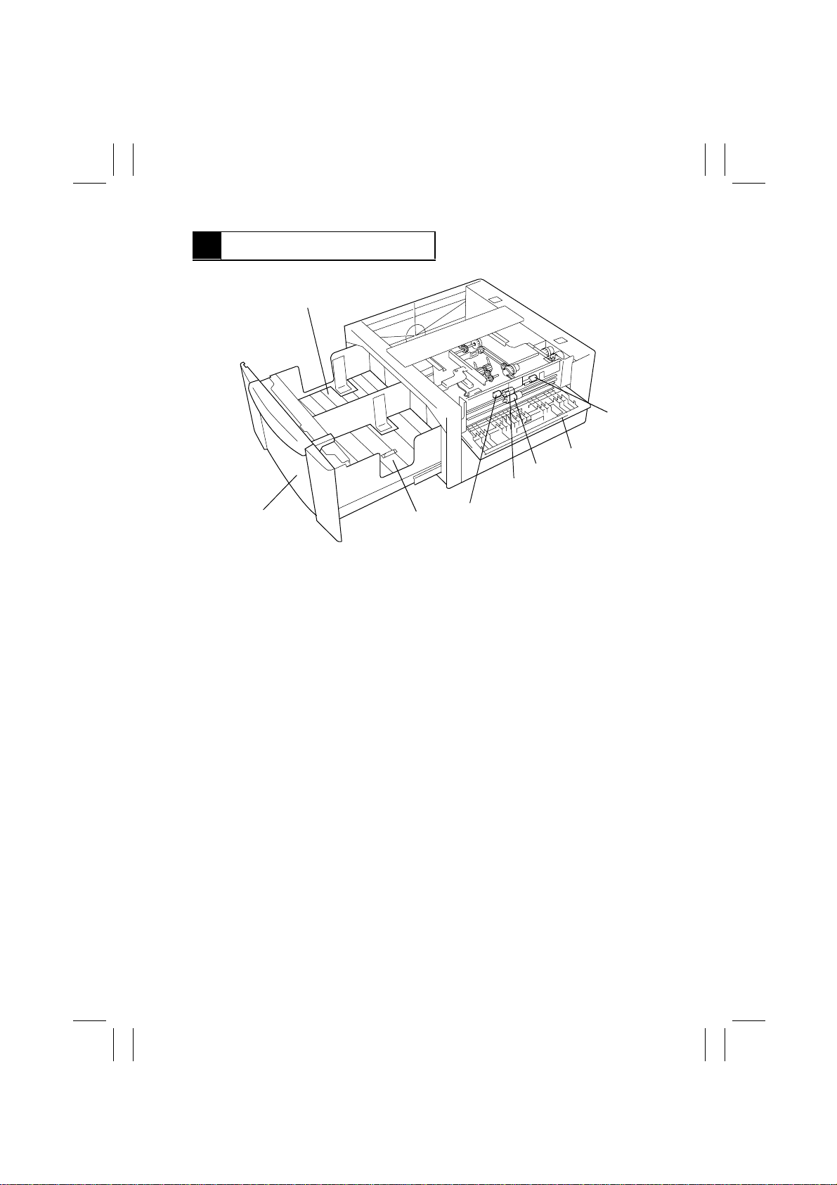
2 PART IDENTIFICATION
1
7
6
5
4
2
1. Lift 2
2. Front Cover
3. Lift 1
4. Feed Roll
3
5. Separator Roll
6. Side Cover
7. Vertical Transport Rolls
7
4496M001AB
M-2
Page 6
FrameMaker Ver.5.5(PC) PF-106 OPTION FOR Di350
98.09.02
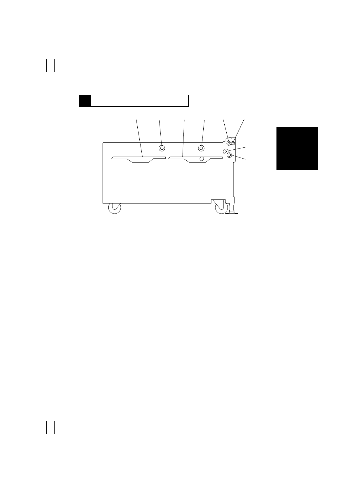
3 CROSS-SECTIONAL VIEW
12 3456
7
8
4496M002AC
1. Lift 2
2. Paper Take-Up Roll 2
3. Lift 1
4. Paper Take-Up Roll 1
5. Vertical Transport Roller
6. Vertical Transport Roll
7. Feed Roll
8. Separator Roll
M-3
Page 7
FrameMaker Ver.5.5(PC) PF-106 OPTION FOR Di350
98.09.02
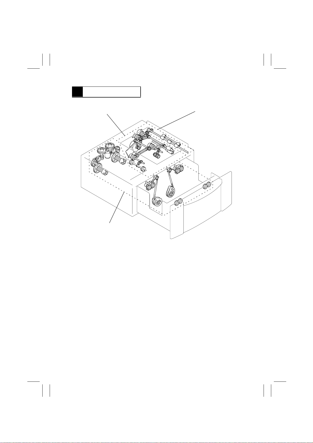
4 DRIVE SYSTEM
Paper Take-Up Drive Mechanism
Lift Drive Mechanism
Vertical Transport Drive Mechanism
4496M003AD
M-4
Page 8
FrameMaker Ver.5.5(PC) PF-106 OPTION FOR Di350
98.09.02
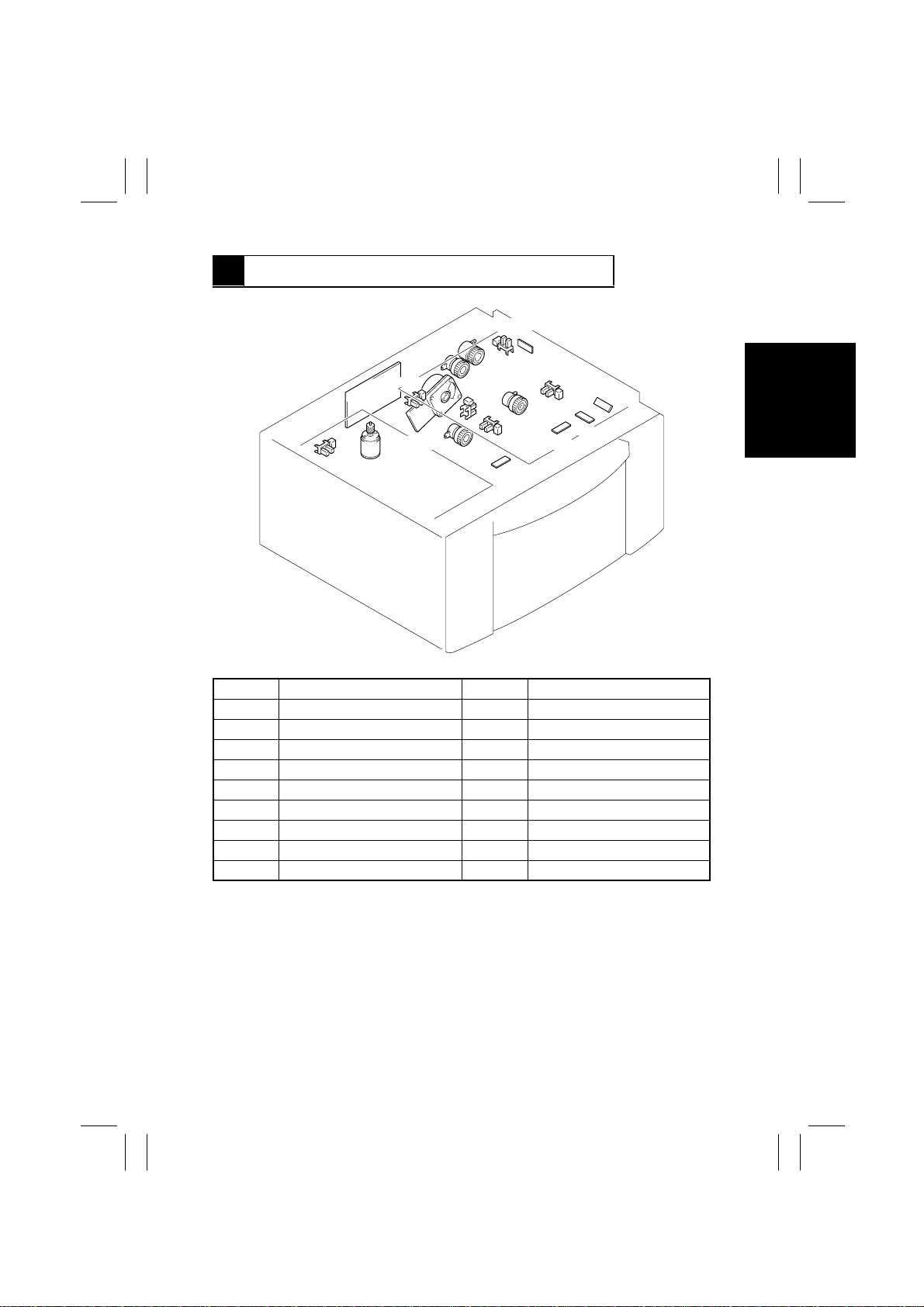
5 ELECTRICAL COMPONENTS LAYOUT
SIDE
RCL
P1CL
LS2
PPS2
RSEN
PPS1
LS1
S1
PPS0
4496M004AA
RS1
PWB-A
HMOT
RS2
EMOT
Symbol Name Symbol Name
PWB-A LCC Main Board PPS2 Paper Empty Sensor 2
HMOT LCC Transport Motor RSEN Registration Sensor
EMOT LCC Lift-Up Motor S1 Paper Standby Position Sensor
P1CL Take-Up Clutch 1 SIDE Side Cover Set Sensor
P2CL Take-Up Clutch 2 FRONT LCC Set Sensor
BCL Separator Clutch RS1 Paper Near Empty Sensor 1
RCL Registration Clutch RS2 Paper Near Empty Sensor 2
PPS0 LCC Take-Up Sensor LS1 Lift-Up Sensor 1
PPS1 Paper Empty Sensor 1 LS2 Lift-Up Sensor 2
BCL
FRONT
P2CL
M-5
Page 9
FrameMaker Ver.5.5(PC) PF-106 OPTION FOR Di350
98.09.02
6 MECHANICAL OPERATIONS
6-1. Vertical Transport Drive Mechanism
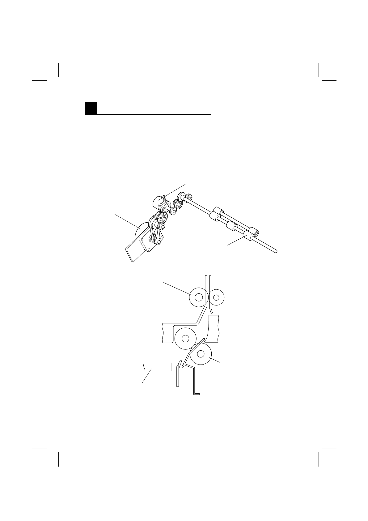
1. Vertical Transport Drive Operation
•
The Vertical Transport Roller is driven by LCC Transport Motor HMOT.
•
The driving force of HMOT is transmitted via a gear train and Registration Clutch RCL to
the Vertical Transport Roller which feeds the paper from Lift 1 or 2 to the copier.
•
Because of the long paper path from Lift 2 involved, skew tends to occur in the paper fed
from Lift 2. Registration Clutch RCL forms a loop in the paper between the Separator
Roll and Vertical Transport Roller, thereby correcting the skew.
Registration Clutch RCL
LCC Transport Motor HMOT
Vertical Transport Roller
Lift 1
Vertical Transport Roller
4496M005AA
Separator Roll
4496M022AA
M-6
Page 10
FrameMaker Ver.5.5(PC) PF-106 OPTION FOR Di350
98.09.02
2. Control of LCC Transport Motor HMOT
A DC motor is used as HMOT which is energized and deenergized by the output signals f ed
through pins 7 to 10 and 12 of CN6 by way of LCC Main Board PWB-A by the Master Board
of the copier.
6-2. Paper Take-Up Mechanism
•
The paper take-up mechanism takes up a sheet of paper from the paper stack on each
lift and feeds it to the Vertical Transport Roller.
•
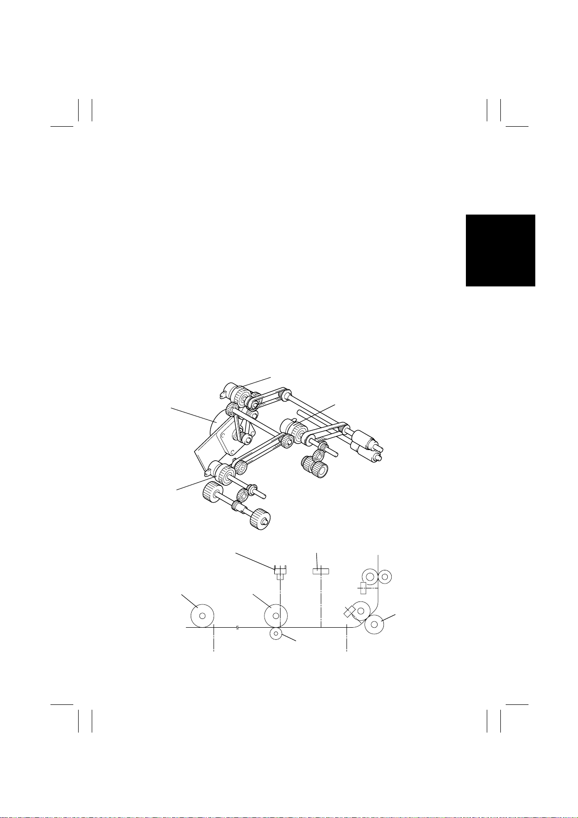
A paper take-up sequence is performed when drive from LCC Transport Motor HMOT is
transmitted via Take-Up Clutch 1/2 P1CL/P2CL to Paper Take-Up Roll 1/2. When Lift 1
runs out of paper, paper is then fed from Lift 2.
•
Mounted beneath Paper Take-Up Roll 1 of Lift 1 is a roll with a torque limiter that prevents
a double feed of the last two sheets of paper.
•
Paper Take-Up Roll 1 is active when paper is fed from Lift 1.
•
When paper is fed from Lift 2, both Paper Take-Up Roll 1 and 2 are active to perform the
paper take-up sequence. In that case, P aper Empty Sensor 1 PPS1 detects that a sheet
of paper has been properly fed through Paper Take-Up Roll 1.
•
The sheet of paper taken up from Lift 1/2 is temporarily stopped at the Paper Standby
Position Sensor to minimize variations in the position of the leading edge of the paper.
When drive is transmitted by Separator Clutch BCL to the Separator Roll, the sheet of
paper is then transported to the Vertical Transport Section.
Separator Clutch BCL
LCC Transport Motor
HMOT
Take-Up Clutch 2
P2CL
Paper Empty Sensor 1 PPS1
Paper Take-Up
Roll 2
Paper Take-Up
Roll 1
Roll with a Torque Limiter
Take-Up Clutch 1 P1CL
4496M006AC
LCC Take-Up Sensor PPS0
Separator Roll
4496M021AB
M-7
Page 11
FrameMaker Ver.5.5(PC) PF-106 OPTION FOR Di350
98.09.02
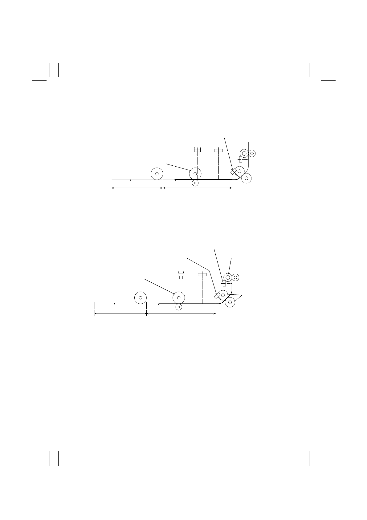
1. Paper take-up from Lift 1
A. After Lift 1 has completed its lifting motion, Paper Take-Up Roll 1 is driven to take up
and feed a sheet of paper until the paper blocks Paper Standby Position Sensor S1.
This serves as the standby position of the paper.
Paper Standby Position Sensor S1
Paper Take-Up Roll 1
Lift 2 Lift 1
4496M030AC
B. When a Paper Take-Up signal is received from the copier, the Separator/Feed Rolls and
Paper Take-Up Roll 1 are driven to transport the paper up to Registration Sensor
RSEN. After RSEN has been blocked, the paper is transported a little further to reach
the Vertical Transport Roller, plus form a registration loop, bef ore being brought to a
stop.
Registration Sensor RSEN
Paper Standby Position
Vertical Transport Roller
Sensor S1
Paper Take-Up Roll 1
Separator/Feed
Roll
Lift 2 Lift 1
4496M026AB
M-8
Page 12
FrameMaker Ver.5.5(PC) PF-106 OPTION FOR Di350
98.09.02
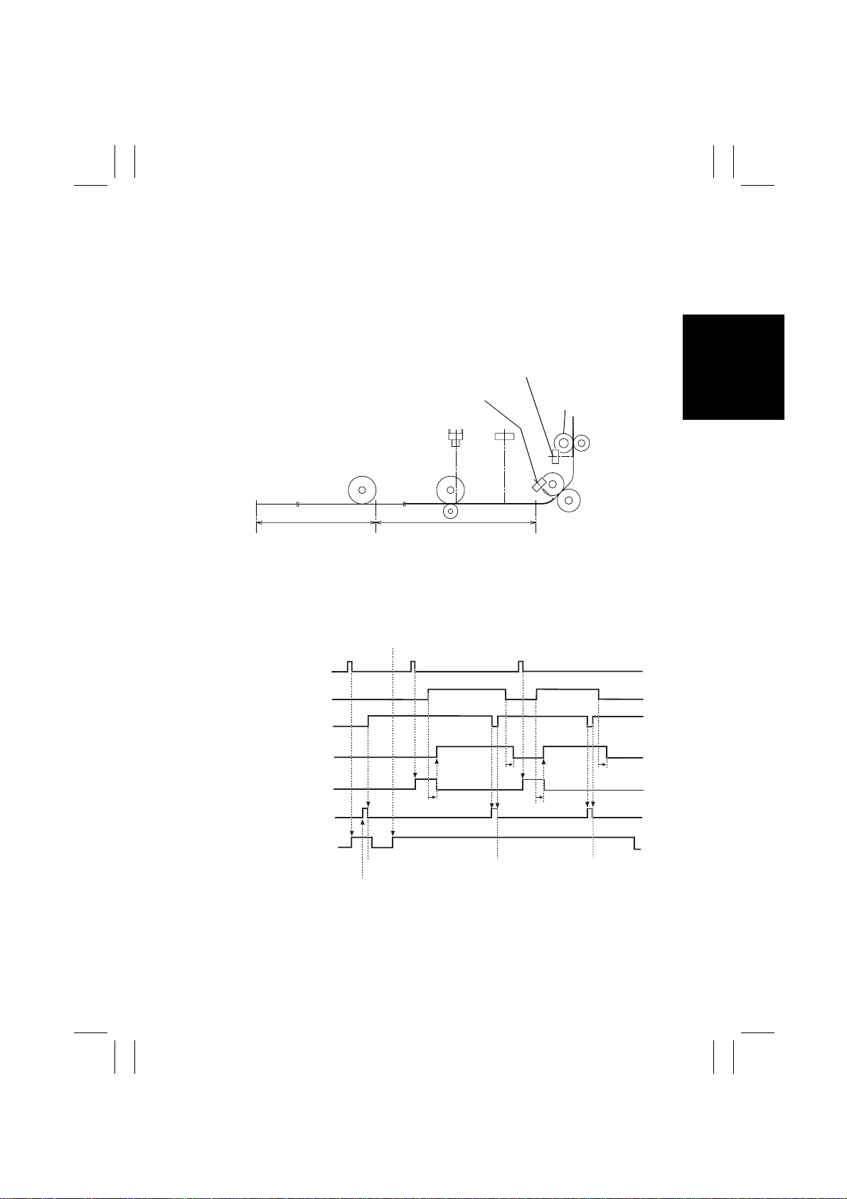
C. The Vertical Transport Roller is driven to transport the paper to the copier. When the
trailing edge of the paper being transported by the Vertical Transpor t Roller unblocks
Paper Standby Position Sensor S1, the subsequent sheet of paper is transported to the
standby position and the LCC waits for the next Paper Take-Up signal to be received.
D. Registration Clutch RCL is deenergized a given period of time after the trailing edge of
the paper being taken up has unblocked Registration Sensor RSEN. The next Paper
Take-Up signal is transmitted after the timer, which is started as the Vertical Transport
Roller starts moving for the preceding sheet of paper, has run out.
Registration Sensor
RSEN
Paper Standby Position
Sensor S1
Vertical T ransport
Roller
Lift 2 Lift 1
4496M027AC
E. The steps B to D are repeated to transport paper from Lift 1.
Taking up and feeding two sheets of paper from Lift 1
Start Key ON
Paper Take-Up Signal P aper Take-Up Signal
Standby Position
After Lift 1 Has Completed Lifting Motion
Copier Signal
Registration Sensor
RSEN
Paper Standby Position
Sensor S1
Registration Clutch
RCL
Separator Clutch
BCL
Take-Up Clutch 1
P1CL
LCC T ransport Motor
HMOT
Operation
Enable Signal
ON
OFF
H
L
H
L
ON
OFF
ON
OFF
ON
OFF
ON
OFF
M-9
Standby Position
Standby Position
4496T07MCB
Page 13
FrameMaker Ver.5.5(PC) PF-106 OPTION FOR Di350
98.09.02
2. Paper take-up from Lift 2
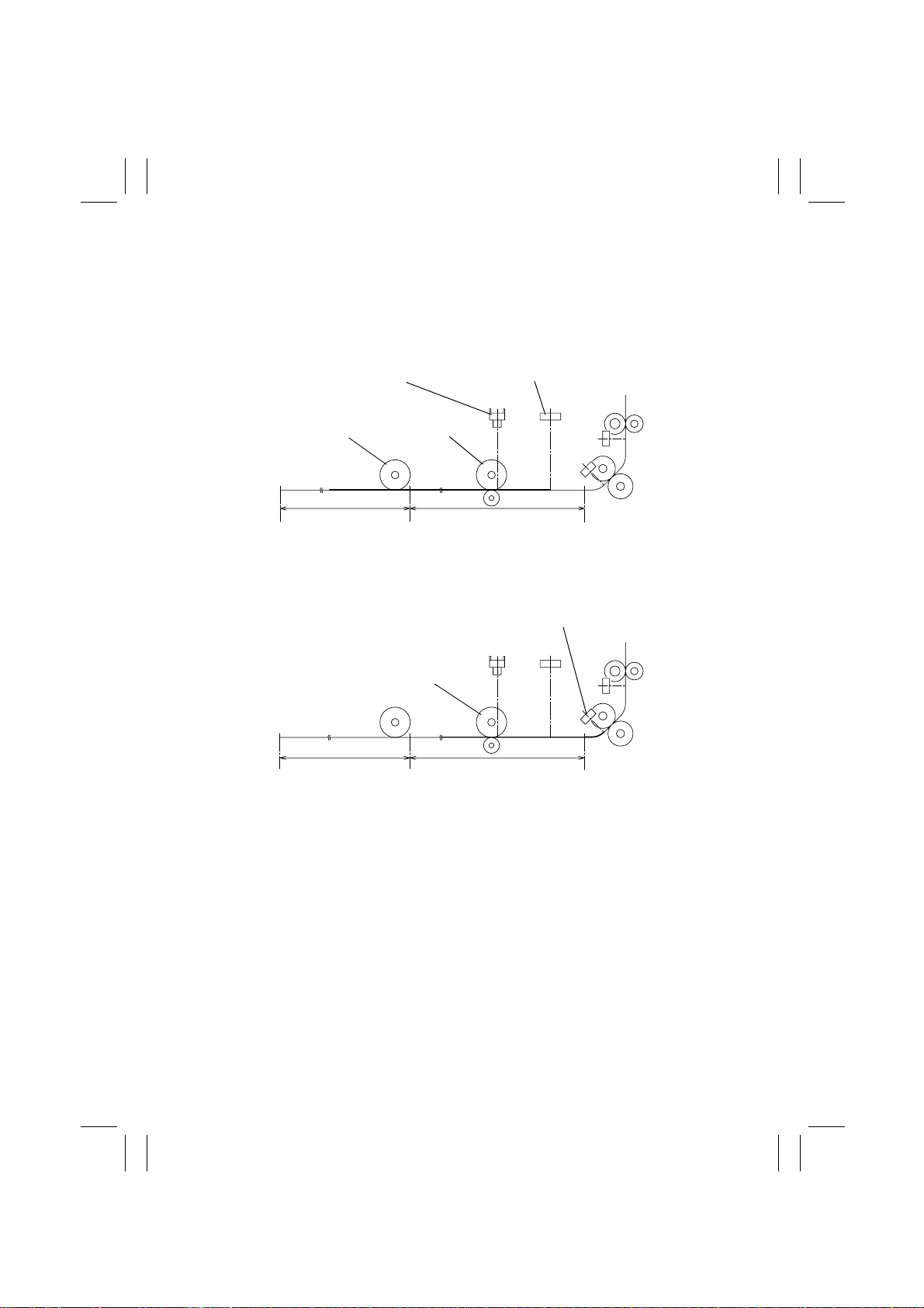
A. When all sheets of paper have been taken up and fed in from Lift 1, Lift 1 is placed in
the top level position to serve as part of the paper path for paper feeding from Lift 2.
B. When the trailing edge of the last sheet of paper from Lift 1 unbl ocks Paper Empty Sen-
sor 1 PPS1, both Paper Take-Up Roll 1 and 2 start turning.
C. The sheet of paper is transported by driving both Paper Take-Up Roll 1 and 2 up to a
point at which LCC Take-Up Sensor PPS0 is blocked.
Paper Empty Sensor 1 PPS1 LCC Take-Up Sensor PPS0
Paper Take-Up
Roll 2
Paper Take-Up
Roll 1
Lift 1Lift 2
4496M028AC
D. Paper Ta ke-Up Roll 1 is driven to transport the paper located at PPS0 up to a point at
which Paper Standby P osition Sensor S1 is blocked. This serves as the standby posi-
tion of the paper.
Paper Standby Position Sensor S1
Paper Take-Up
Roll 1
Lift 2 Lift 1
4496M030AC
M-10
Page 14
FrameMaker Ver.5.5(PC) PF-106 OPTION FOR Di350
98.09.02
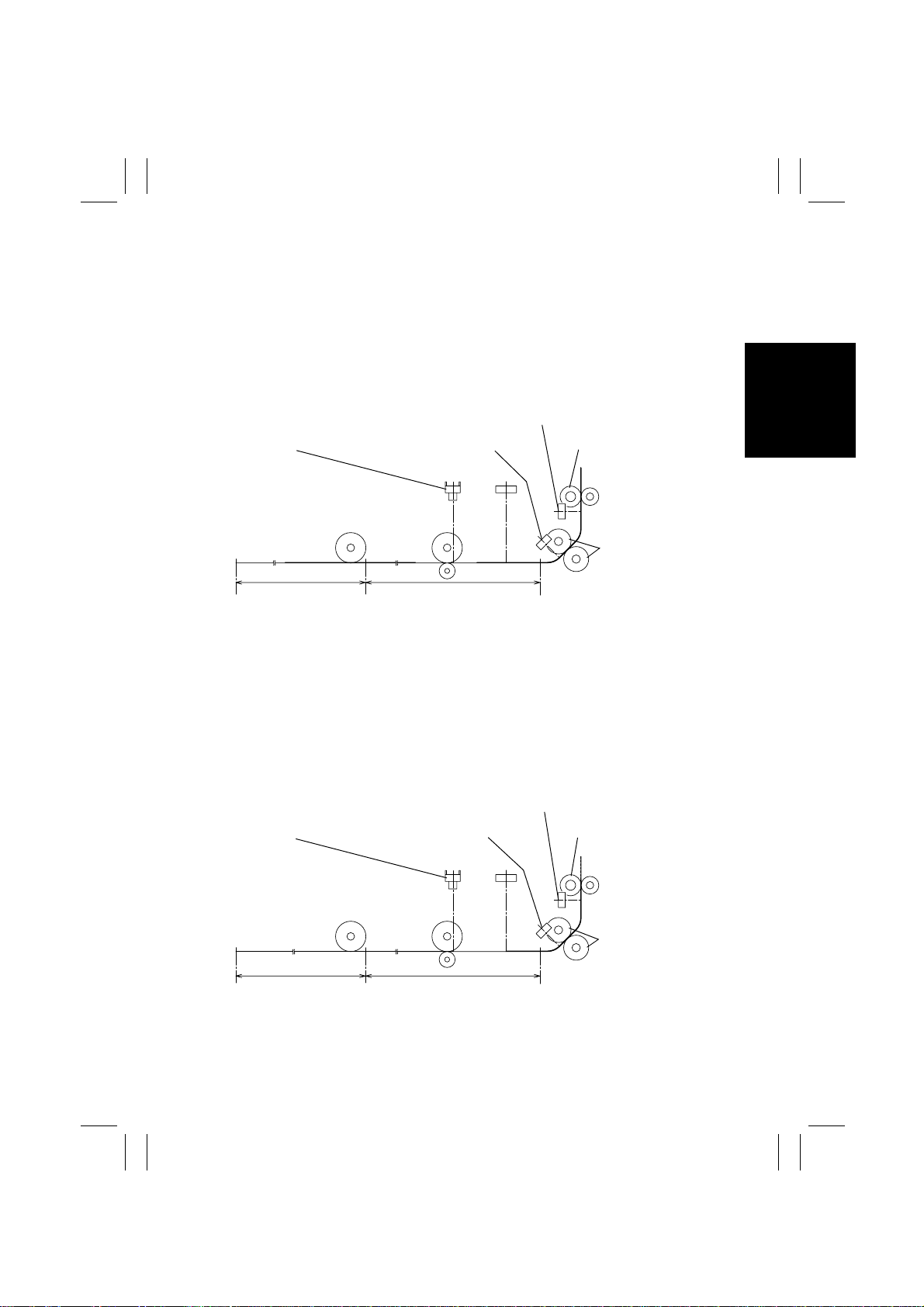
E. When a Paper Take-Up signal is received from the copier, the Separator/Feed Rolls and
Paper Take-Up Roll 1 are driven to transport the paper up to Registration Sensor
RSEN. After RSEN has been blocked, the paper is transported a little further to reach
the Vertical Transport Roller, plus form a registration loop, bef ore being brought to a
stop.
F. The Vertical Transport Roller is driven to transport the paper to the copier. When the
trailing edge of the paper being transported by the Vertical Transpor t Roller unblocks
Paper Empty Sensor 1 PPS1, Paper Take-Up Roll 1 and 2 are driven to transport the
subsequent sheet of paper to a position at which PPS1 is blocked.
Registration Sensor RSEN
Paper Empty Sensor 1
PPS1
Paper Standby Position
Sensor S1
Vertical Transpor t Roller
Separator/Feed
Roll
Lift 2 Lift 1
4496M029AC
G. A given period of time after the trailing edge of the preceding sheet of paper has
unblocked LCC Take-Up Sensor PPS0, the subsequent sheet of paper located at PPS1
is transported to the standby position. LCC then waits for the next Paper Take-Up signal
to be received.
If no paper is present at the point at which the trailing edge of the preceding sheet of
paper is supposed to block S1 when the subsequent sheet of paper blocks PPS1, the
subsequent sheet of paper is transported to the standby position without being stopped
and the LCC waits for the next Paper Take-Up signal.
Registration Sensor RSEN
PPS1
Paper Standby Position
Sensor S1
Vertical T ransport RollerPaper Empty Sensor 1
Separator/Feed
Roll
Lift 2 Lift 1
4496M025AC
M-11
Page 15
FrameMaker Ver.5.5(PC) PF-106 OPTION FOR Di350
98.09.02
H. Registration Clutch RCL is deenergized a given period of time after the trailing edge of
the paper being taken up has unblocked Registration Sensor RSEN. The next Paper
Take-Up signal is transmitted after the timer, which is started as the Vertical Transport
Roller starts moving for the preceding sheet of paper, has run out.
I. The steps E to H are repeated to transport paper from Lift 2.
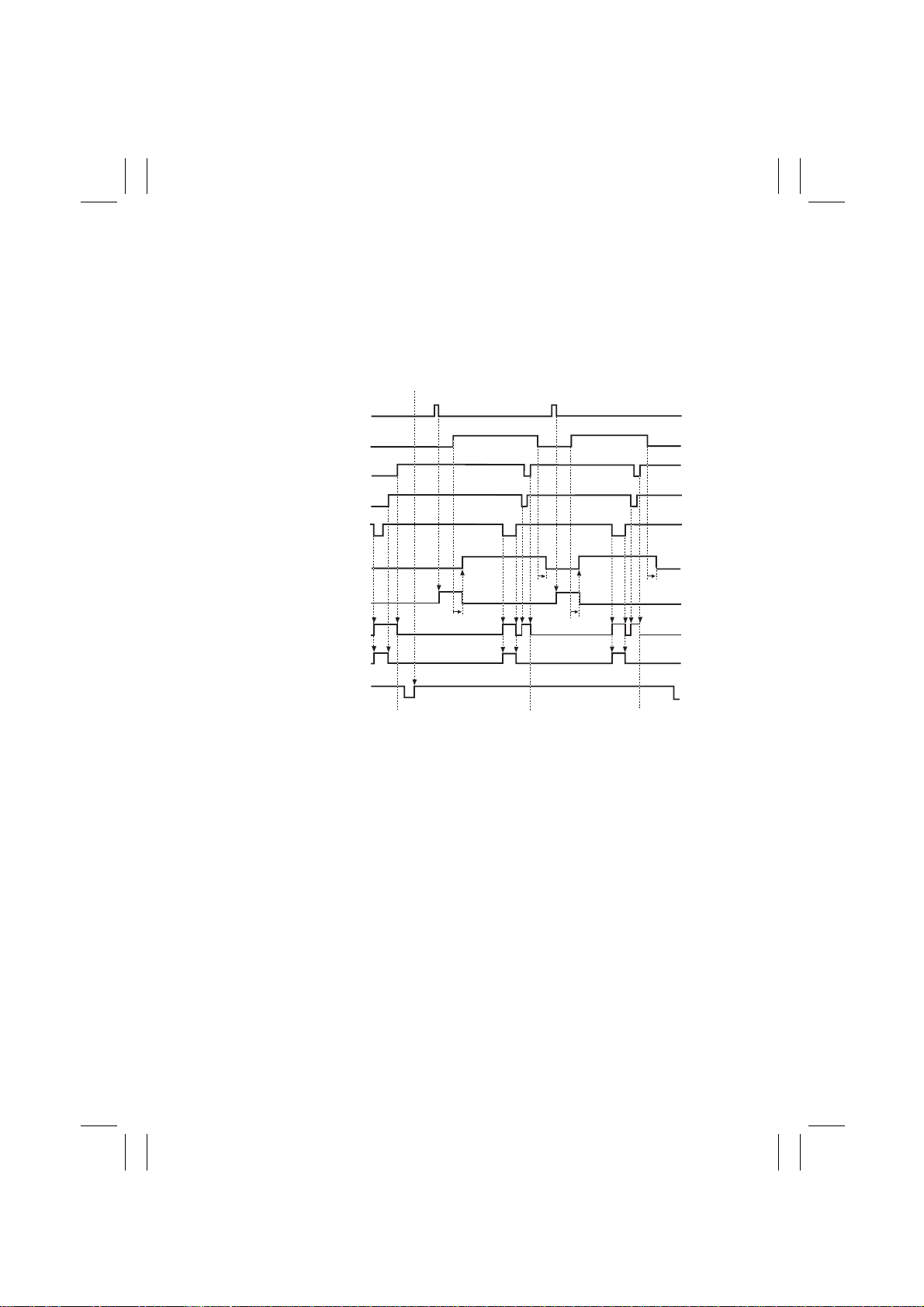
Taking up and feeding two sheets of paper from Lift 2
Start Key ON
Copier Signal
Registration Sensor
RSEN
Paper Standby Position
Sensor S1
LCC T ake-Up Sensor
PPS0
Paper Empty Sensor 1
PPS1
Registration Clutch
RCL
Separator Clutch
BCL
Take-Up Clutch 1
P1CL
Take-Up Clutch 2
P2CL
LCC T ransport Motor
HMOT
ON
OFF
H
L
H
L
H
L
H
L
ON
OFF
ON
OFF
ON
OFF
ON
OFF
ON
OFF
Standby Position
Paper Take-Up Signal P aper Take-Up Signal
Standby Position Standby Position
4496T08MCB
M-12
Page 16
FrameMaker Ver.5.5(PC) PF-106 OPTION FOR Di350
98.09.02
6-3. Paper Take-Up Retry Control
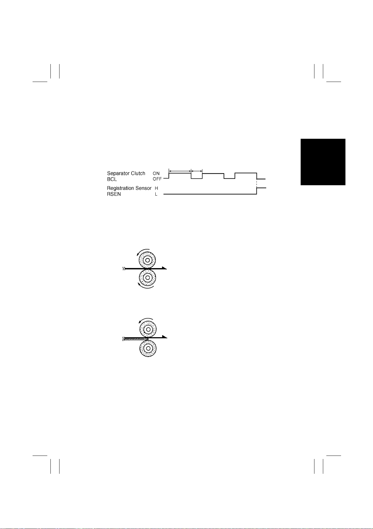
To minimize the occurrence of paper misfeed due to a slippery P aper Take-Up Roll, Separator Clutch BCL is energized a second time if a sheet of paper fails to reach Registration
Sensor RSEN within a given period of time after BCL has first been energized.
The control timing is as follows.
A paper misfeed results if the sheet of paper does not reach the Registration Sensor even
after three paper take-up sequences.
4496T09MCB
6-4. Paper Separating Mechanism
The paper separating mechanism employs a system with a torque limiter that is fitted to the
Separator Roll shaft and stops the Separator Roll when there is a change in friction
between the Feed and Separator Rolls.
<Normal Feeding>
When only one sheet of paper is fed, the friction
Feed Roll
Paper
Separator Roll
4425M012AA
Driven or stationary
coefficient on the top side of the paper is equal to
that on the underside. Driven by the Feed Roll,
the paper drives the Separator Roll. This causes
the paper to be sent to the Vertical Transport Section.
The friction coefficient varies for dif ferent ambient
conditions and types of paper being used, which
often causes the Separator Roll to be stationary.
<Double Feeding>
Feed Roll
1st Sheet of Paper
2nd Sheet of Paper
Separator Roll
4425M013AA
Stationary
Since the friction coefficient between the underside of the second sheet of paper and Separator
Roll is greater than that between the first and second sheets of paper, the Separator Roll is not
driven and holds the second sheet of paper at the
nip, allowing only the first sheet of paper to be f ed
to the Vertical Transport Section.
M-13
Page 17
FrameMaker Ver.5.5(PC) PF-106 OPTION FOR Di350
98.09.02
6-5. Paper Pressure Releasing Mechanism
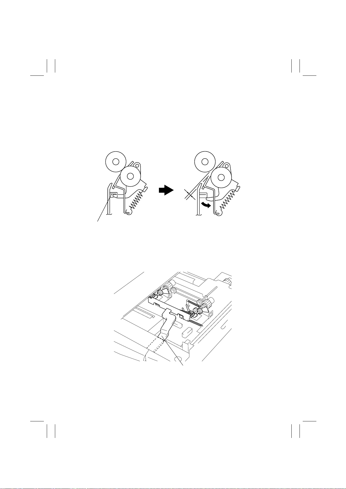
•
The LCC is provided with a mechanism that releases the pressure between the F eed and
Separator Rolls and between the paper and Paper Take-Up Roll when the LCC is slid out
of the copier.
•
The pressure between the Feed and Separator Rolls is released by the Separator Roll
Assy and the Pressure Release Rail above the rail on the paper take-up end. When LCC
is pulled out, the Pressure Release Rail pushes the Separator Roll Assy downward, thus
releasing the pressure between the Feed and Separator Roll.
4496M007AB 4496M008AB
Pressure Release Rail
6-6. Paper Take-Up Roll Retracting Mechanism
The pressure between the paper and Paper Take-Up Roll is released by the projection on
the back side of the Front Cover, Pressure Release Lever, and Paper Take-Up Roll Assy.
When the LCC is slid out, it releases the Pressure Release Lever, which pushes the P aper
Take-Up Roll upward to release pressure between the paper and Paper Take-Up Roll.
4496M009AA
Pressure Release Lever
M-14
Page 18
FrameMaker Ver.5.5(PC) PF-106 OPTION FOR Di350
98.09.02
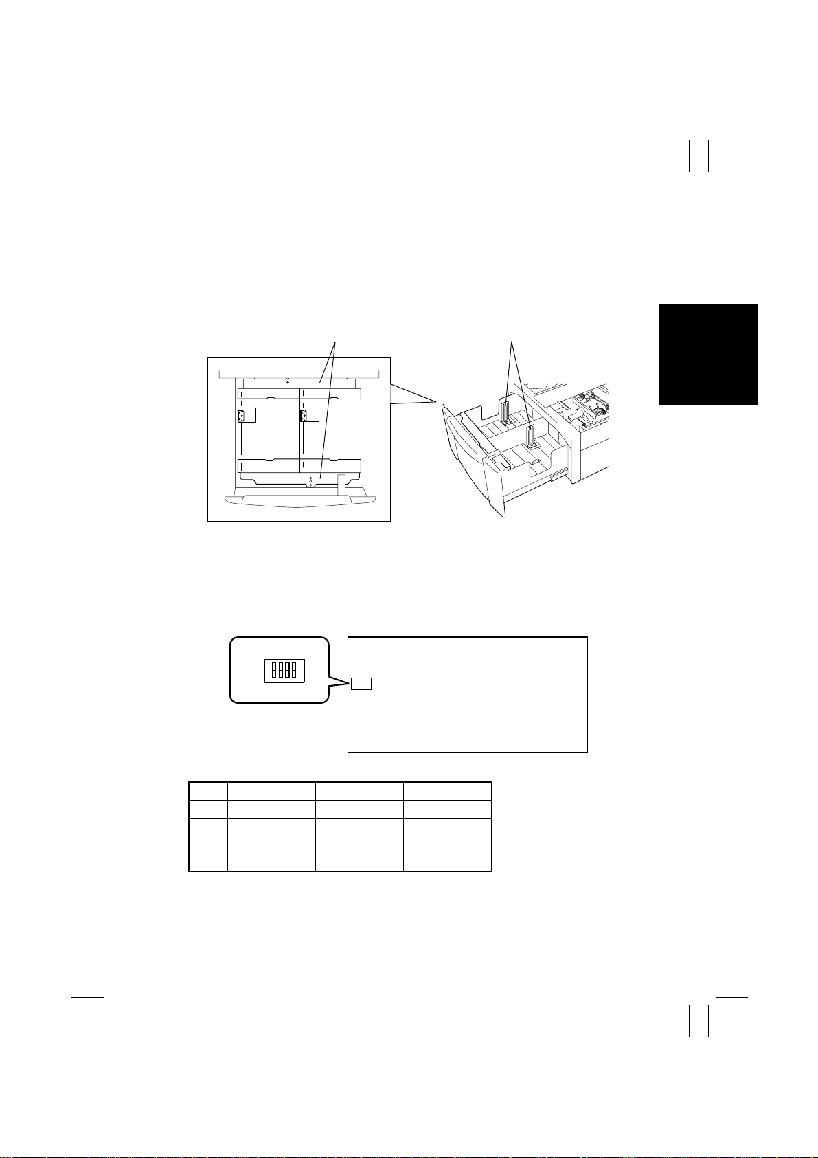
6-7. Edge Guides and Trailing Edge Stop
The Trailing Edge Stop is screwed into position (not used for Letter crosswise).
Edge Guides can be slid into any desired position.
Whenever the positions of t he Edge Guides and Trailing Edge Stop have been changed, be
sure to perform the paper size setting procedure. (See “Paper Size Setting” that follows.)
✽
The inch area LCC can be set for Letter crosswise only.
Edge Guides Trailing Edge Stops
4496M010AA
4496M011AA
6-8. Paper Size Setting
The paper sizes that can be set are A4 crosswise, B5 crosswise , and Letter crosswise .
After the positions of the Edge Guides and Trailing Edge Stop have been changed, place
the DIP switch keys on LCC Main Board PWB-A in the corresponding positions according
to the current paper size.
SW1
ON
1234
OFF
SW1 Letter Crosswise A4 Crosswise B5 Crosswise
1 OFF ON OFF
2 OFF OFF ON
3 OFF OFF OFF
4 OFF OFF OFF
PWB-A
4496M019AB
M-15
Page 19
FrameMaker Ver.5.5(PC) PF-106 OPTION FOR Di350
98.09.02
6-9. LCC-in-Position Detection
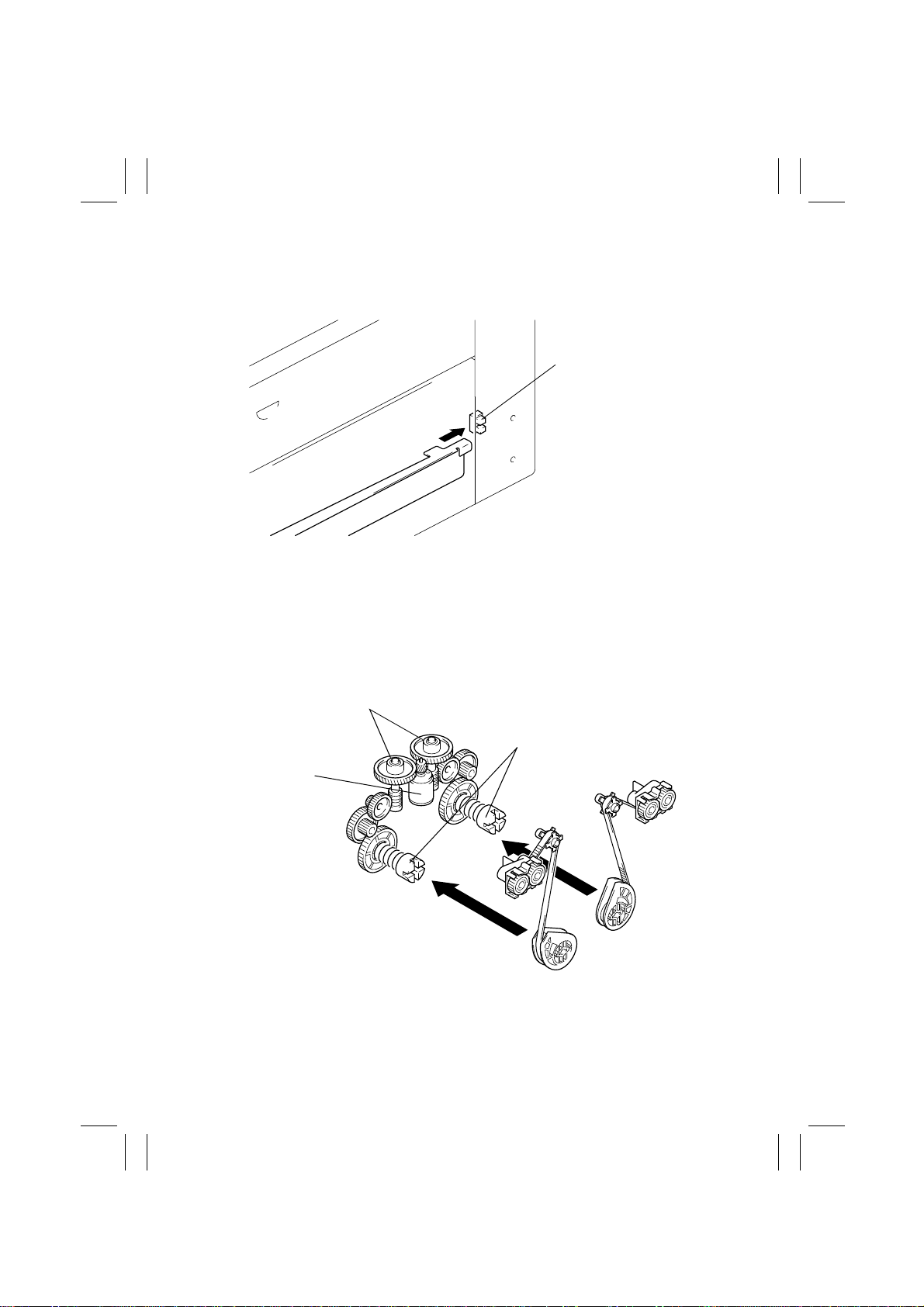
The LCC is detected at its closed position when the light blocking plate provided on the rear
end of the right rail blocks LCC Set Sensor FRONT.
LCC Set Sensor FRONT
4496M012AA
6-10. Lifting Mechanism
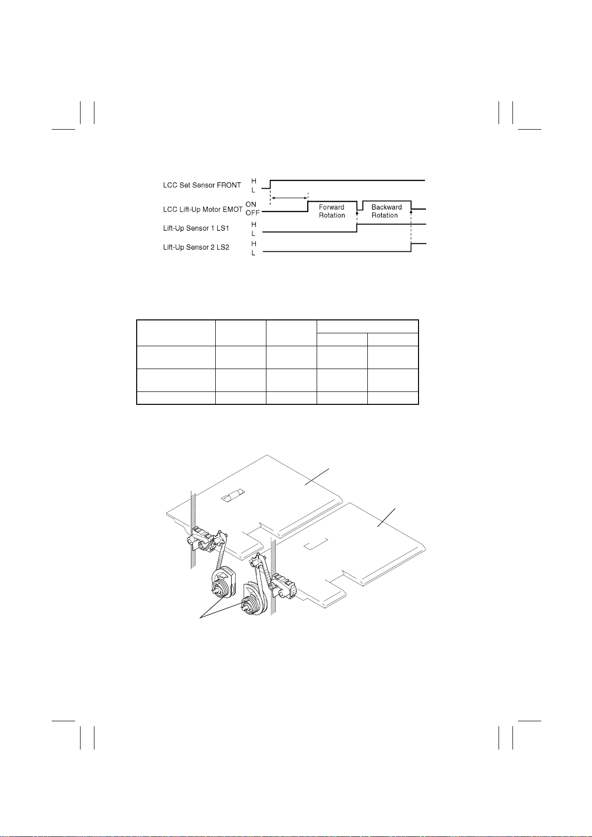
When the LCC is slid into the copier, the couplings are engaged. When LCC Lift-Up Motor
EMOT turns forward and backward, its drive is transmitted via a one-way gear and gear
train to raise Lift 1 and Lift 2, in that order.
A one-way gear is in each of the Lift 1 and 2 drive mechanisms. When EMOT turns forward, its drive is transmitted to Lift 1 and when the motor turns backward, its drive is transmitted to Lift 2.
One-Way Gears
LCC Lift-Up Motor
EMOT
Couplings
4496M013AB
M-16
Page 20
FrameMaker Ver.5.5(PC) PF-106 OPTION FOR Di350
98.09.02
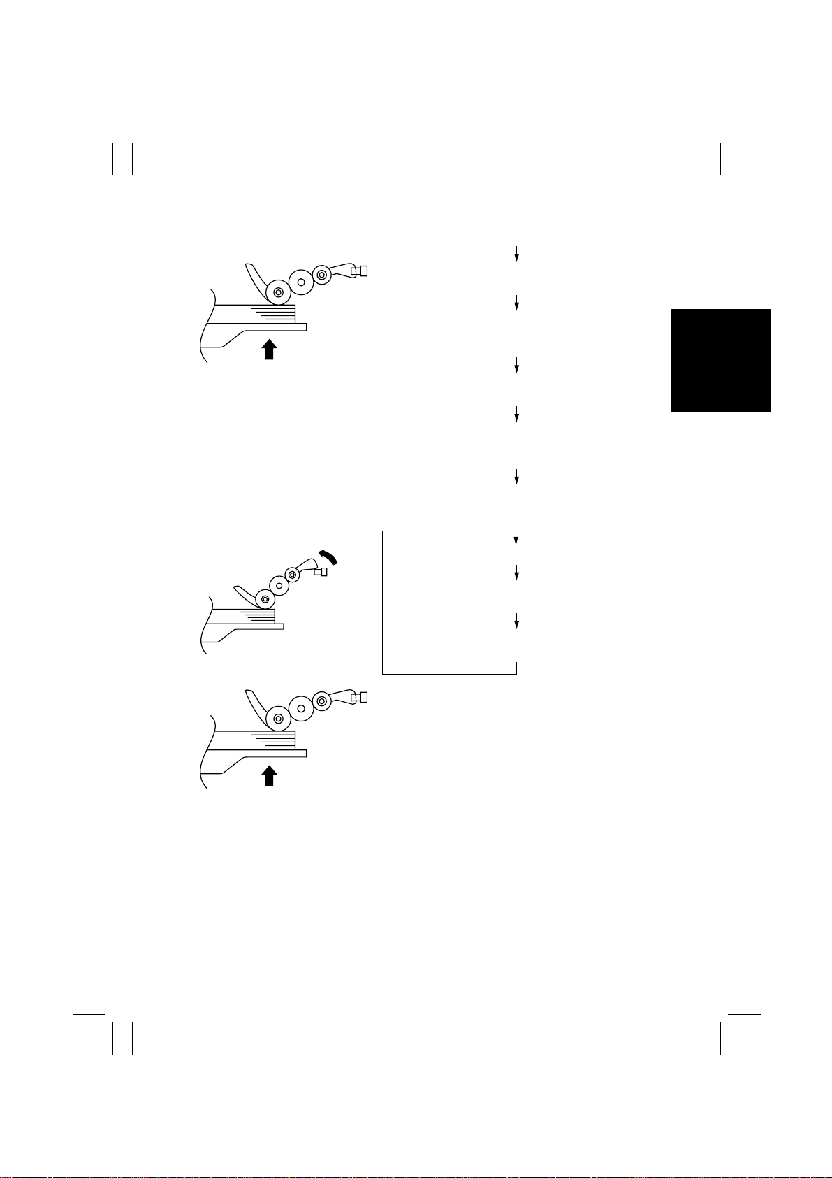
When LCC is Slid in:
During a Copy Cycle:
4496M014AB
4496M015AB
LCC Set Sensor FRONT is blocked.
LCC Lift-Up Motor EMOT turns forward to raise
Lift 1.
The paper stack causes the light blocking plate of
the Paper Take-Up Roll 1 Assy to block Lift-Up
Sensor 1 LS1.
EMOT is deenergized and then energized to start
turning backward, thereby raising Lift 2.
The paper stack causes the light blocking plate of
the Paper Take-Up Roll 2 Assy to block Lift-Up
Sensor 2 LS2.
EMOT is deenergized.
Paper is consumed as copy cycles are run.
The Paper Take-Up Roll gradually lowers,
unblocking the Lift-Up Sensor.
EMOT is energized and the Lift is raised. This lifts
the paper stack to block the Lift-Up Sensor.
4496M014AB
Both Lift 1 and 2 perform these sequences of operations to keep a given pressure between
the paper and Paper Take-Up Roll.
1. Lift 1 and 2 Ascent Conditions
•
The LCC is slid into position.
•
The Lift-Up Sensor is unblocked whil e a paper take-up sequence is being carried out with
paper present on the Lift.
2. Lift 1 and 2 Stop Conditions
•
The Lift-Up Sensor is blocked.
•
The Lift-Up Sensor is blocked while the paper stack top level posi tion is being corrected.
M-17
Page 21
FrameMaker Ver.5.5(PC) PF-106 OPTION FOR Di350
98.09.02
When LCC is Slid in:
4496T10MCB
3. LCC Lift-Up Motor EMOT Control
LCC Lift-Up Motor EMOT is a DC motor. It is energized or deenergized and its direction of
rotation is determined by the Motor Control signals applied from the copier’s Master Board
to pins 1 and 2 of CN5 of LCC Main Board PWB-A.
EMOT Lift 1 Lift 2
Energized
(Forward Rotation)
Energized
(Backward Rotation)
Ascent Stop H L
Stop Ascent L H
CN5
12
Deenergized Stop Stop L L
4. Descent Motion
When the LCC is slid out of the copier, Lift 1 and 2 are lowered. To absorb shocks that
would otherwise be applied during the descent motion, springs are loaded in the rear side
of the LCC.
Lift 1
Lift 2
4496M024AA
Springs
M-18
Page 22
FrameMaker Ver.5.5(PC) PF-106 OPTION FOR Di350
98.09.02
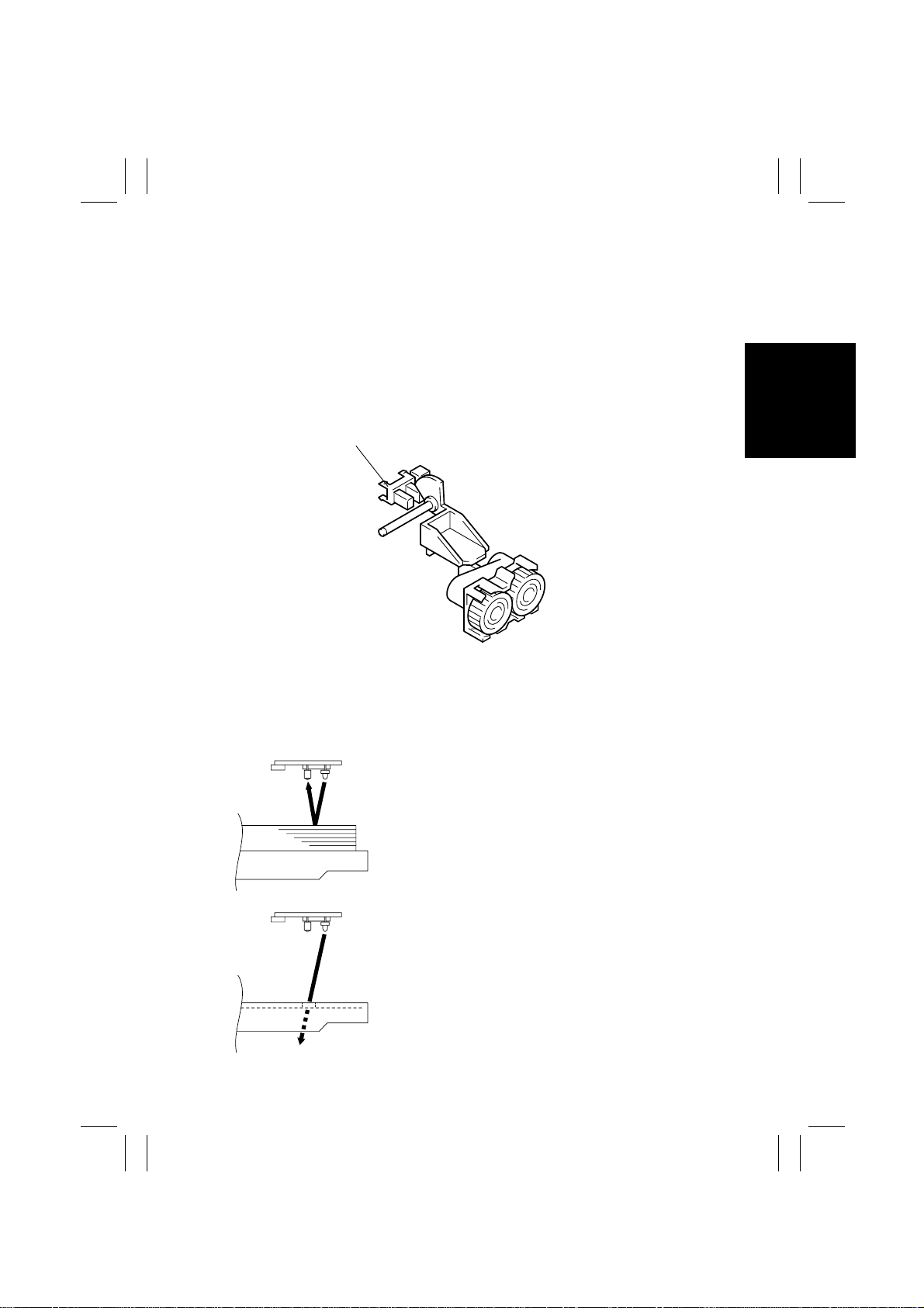
6-11. Paper Near Empty Detection
A paper-near-empty condition is detected by sensing the height of Lift 1 or Lift 2. When
paper is consumed during a copy cycle, Lift 1 or 2 gradually mov es up. This eventually
blocks the Paper Near Empty Sensor, at which timing the copier determines that the LCC
will soon run out of paper (the amount of paper (80 g/m
sheets) and gives a corresponding message on the Touch Panel.
Since the amount of paper still av ai lab le for use varies while a paper tak e-up sequence is i n
progress, detection is made at a timing when the Paper Take-Up Roll is in the retracted
position.
Paper Near Empty Sensor 1/2
RS1/RS2
2
) still available for use is 100 ±50
4496M023AA
6-12. Paper Empty Detection
A paper-empty condition is detected by a reflector type photosensor, Paper Empty Sensor
1 PPS1 and Paper Empty Sensor 2 PPS2, installed in the Paper Take-Up Unit. When a
paper-empty condition is detected, the corresponding message is displayed on the Touc h
Panel.
•
When Paper is Loaded
The light from the LED of Paper Empty Sensor 1
PPS1 or Paper Empty Sensor 2 PPS2 is
reflected, with which the copier determines that
there is paper in LCC.
4496M018AA
•
When No Paper is Loaded
The light from the LED of Paper Empty Sensor 1
PPS1 or Paper Empty Sensor 2 PPS2 is not
reflected, with which the copier determines that
there is no paper loaded in the LCC.
4496M017AA
M-19
Page 23
FrameMaker Ver.5.5(PC) PF-106 OPTION FOR Di350
98.09.02
Panel Display
Lift 1
Paper-near-empty Paper-empty
Lift 2
❍
: Paper-near-empty display : Paper-empty display
Paper-near-empty
Paper-empty
❍❍
❍
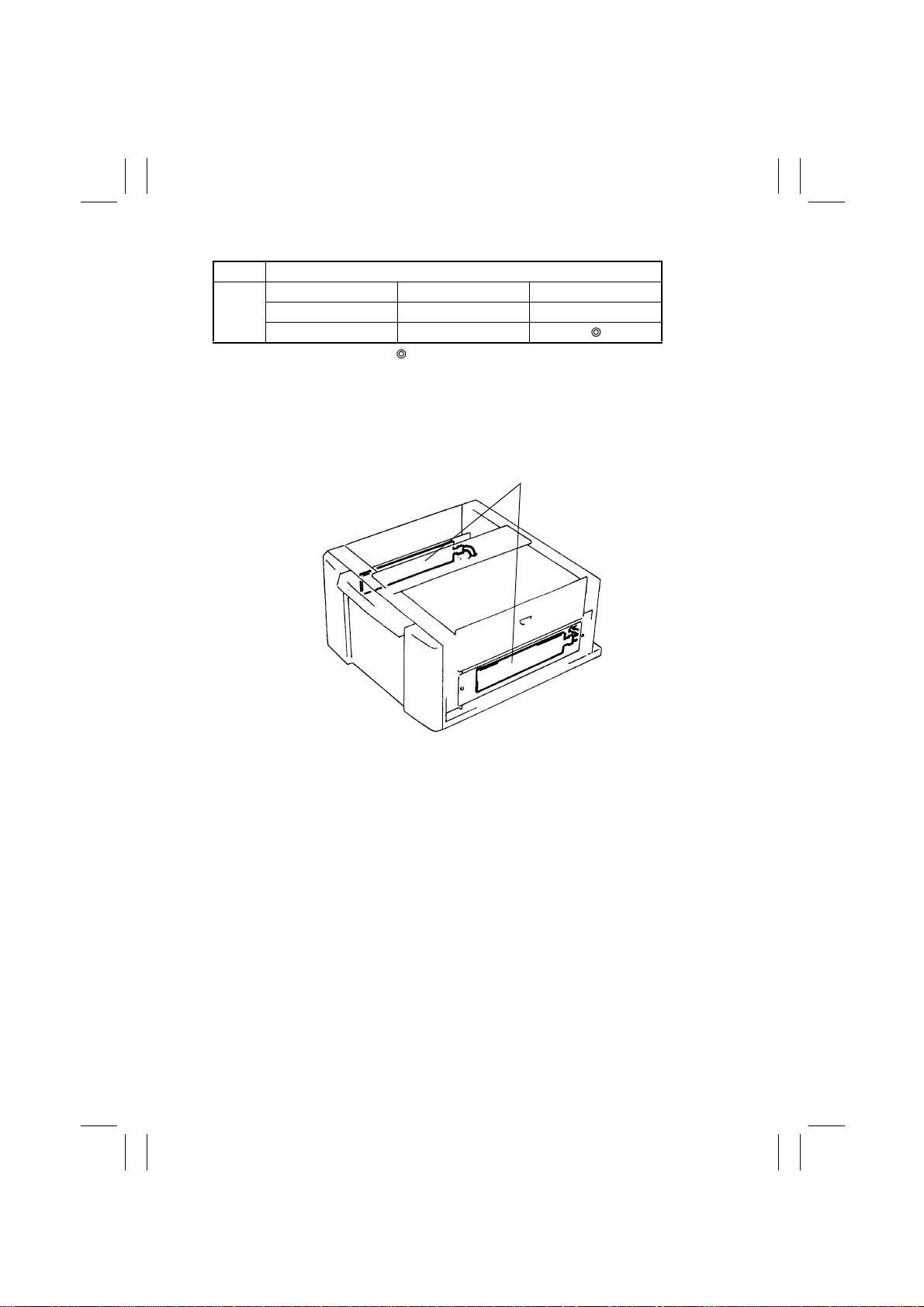
6-13. Paper Dehumidifying Heaters (Option)
To prevent paper passage performance from being degraded by damp paper under highly
humid conditions, Paper Dehumidifier Heaters are mounted on both sides of the LCC. As
long as the power cord is plugged in, these heaters are kept ON at all times.
Paper Dehumidifying Heaters
M-20
4496M031AA
Page 24

FrameMaker Ver.5.5(PC) PF-106 OPTION FOR Di350
98.09.02
DIS/REASSEMBLY,
ADJUSTMENT
Page 25
FrameMaker Ver.5.5(PC) PF-106 OPTION FOR Di350
98.09.02
1 DISASSEMBLY
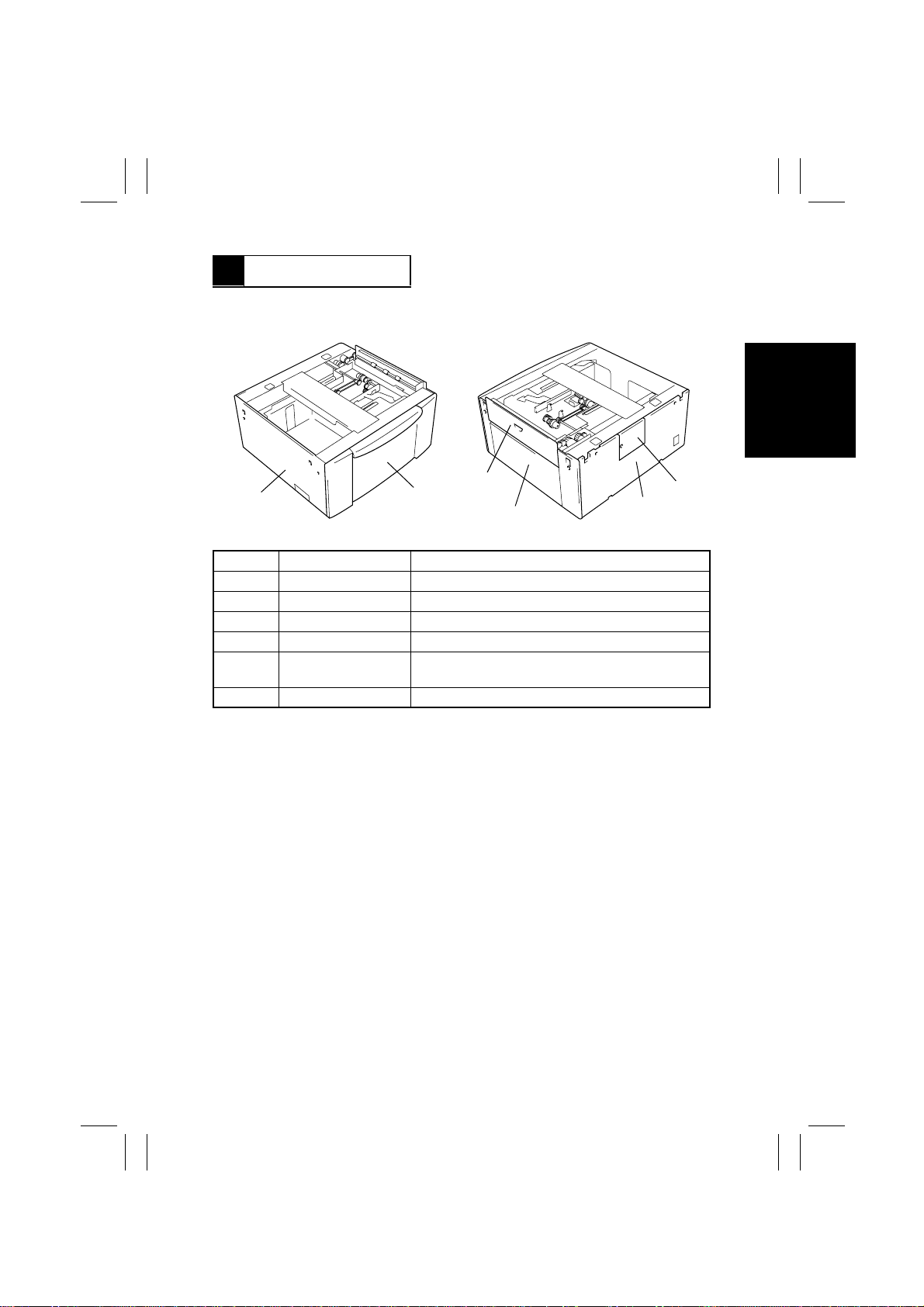
1-1. Removal of Exterior Parts
1
No. Part Name Removal Steps
1 Left Cover Remove two screws.
2 Front Cover Slide out the LCC and remove three screws.
3 Side Panel Open the Side Panel.
4 Right Cover Remove two screws.
5 Rear Cover
6 Maintenance Panel Remove one screw.
2
4496D001AA
After the Maintenance Panel has been removed,
remove four screws.
3
4
6
5
4496D002AA
D-1
Page 26
FrameMaker Ver.5.5(PC) PF-106 OPTION FOR Di350
98.09.02
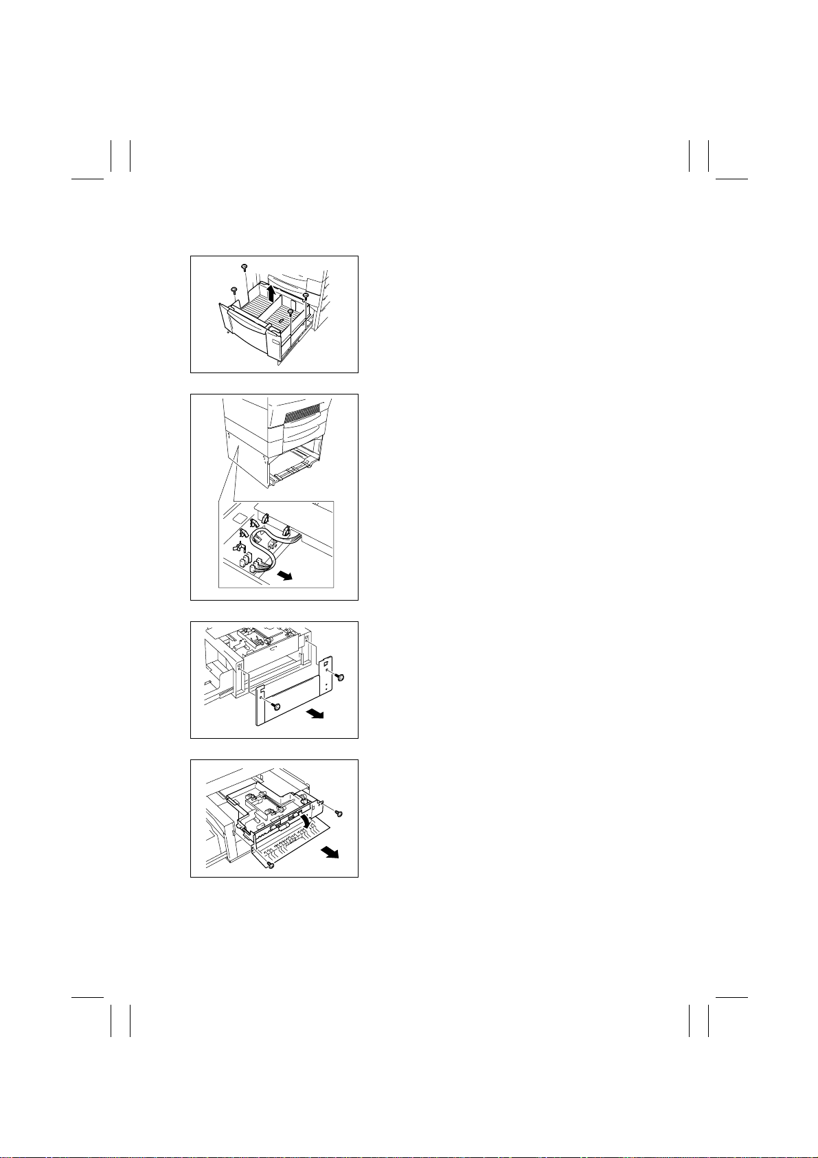
1-2. Removal of the Paper Take-Up Unit
1. Remove the LCC.
4496D003AB
2. Unplug three connectors and remove the harness from five cord clamps.
4496D004AB
4496D005AB
4496D006AB
3. Remove two screws and the Right Cover.
4. Open the Side Panel.
5. Remove two screws and the Paper Take-Up
Unit.
D-2
Page 27
FrameMaker Ver.5.5(PC) PF-106 OPTION FOR Di350
98.09.02
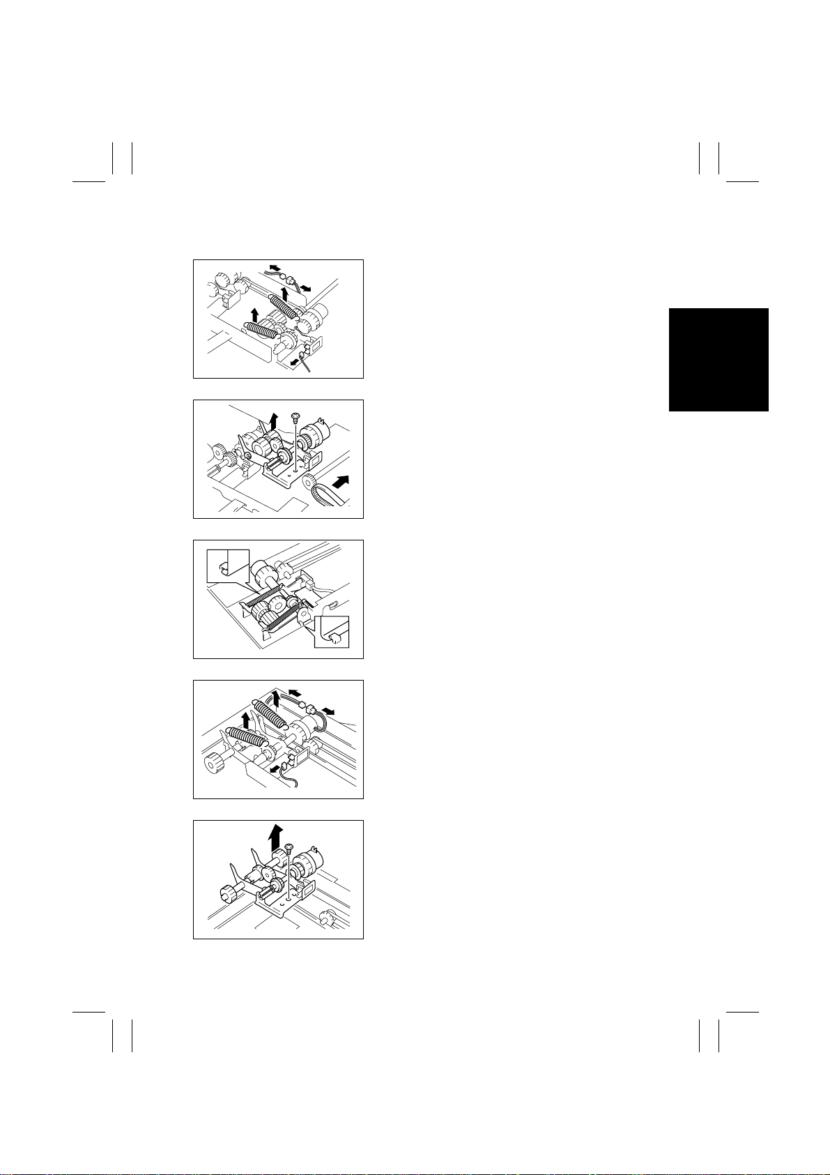
1-3. Removal of the Paper Take-Up Rolls
1. Remove the Paper Take-Up Unit.
2. Unplug one connector of Lift-Up Sensor 1 and
another of Take-Up Clutch 1 of the right Paper
Take-Up Roll Assy.
3. Unhook two springs.
4496D007AC
4. Remove one screw and, while removing the timing belt toward the clutch side, remov e the right
Paper Take-Up Roll Assy.
4496D008AC
4496D011AC
4496D009AD
4496D010AD
When mounting the right Paper Take-Up Roll Assy,
fit the ends of the assy into position as shown.
5. Unplug one connector of Lift-Up Sensor 2 and
another of Take-Up Clutch 2 of the left Paper
Take-Up Roll Assy.
6. Unhook two springs.
7. Remove one screw and the left Paper Take-Up
Roll Assy.
D-3
Page 28
FrameMaker Ver.5.5(PC) PF-106 OPTION FOR Di350
98.09.02
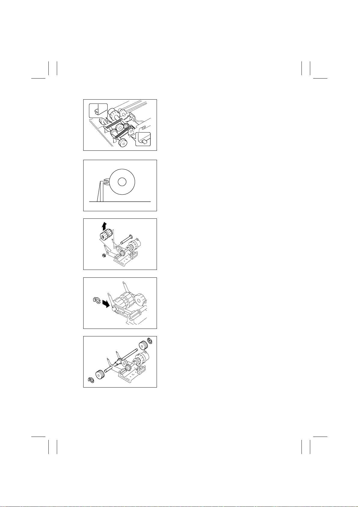
When mounting the left Paper Take-Up Roll Assy, fit
the ends of the assy into position as shown.
4496D011AD
When mounting the Paper Tak e-Up Roll Assys, fit
the Take-Up Clutch into position as shown.
4496D012AB
8. Snap off one C-clip from the Paper Take-Up Roll
1 shaft.
9. Take the shaft and Paper Take-Up Roll 1 apart.
4496D013AC
4496D014AC
4496D013AD
When mounting Paper Take-Up Roll 1, face the Cclip as shown.
10. Snap off two C-clips and take off Paper Take-Up
Roll 2.
D-4
Page 29
FrameMaker Ver.5.5(PC) PF-106 OPTION FOR Di350
98.09.02
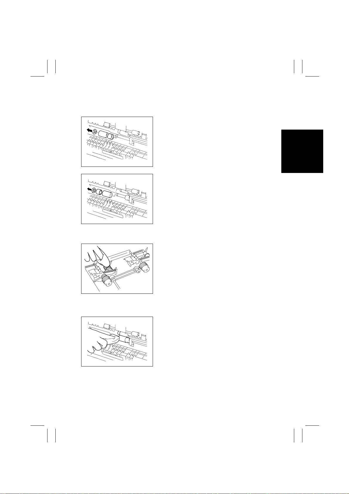
1-4. Removal of the Feed Roll, Separator Roll and Torque Limiter
Assy.
1. Open the Side Cover.
2. Snap off one C-clip from the Separator Roll shaft
and remove the Separator Roll and Torque Limiter Assy.
4496D023AA
3. Snap off one C-clip from the Feed Roll shaft and
remove the Feed Roll.
4496D016AB
1-5. Cleaning of the Paper Take-Up Roll
1. Remove the Paper Take-Up Unit.
2. Wipe the surface of Paper Take-Up Roll 1 & 2
clean with a soft cloth dampened with alcohol.
4496D017AC
1-6. Cleaning of the Feed Roll and Separator Roll
1. Open the Side Panel.
2. Wipe the surface of the Feed/Separator Roll
clean with a soft cloth dampened with alcohol.
4496D018AA
D-5
Page 30
FrameMaker Ver.5.5(PC) PF-106 OPTION FOR Di350
98.09.02
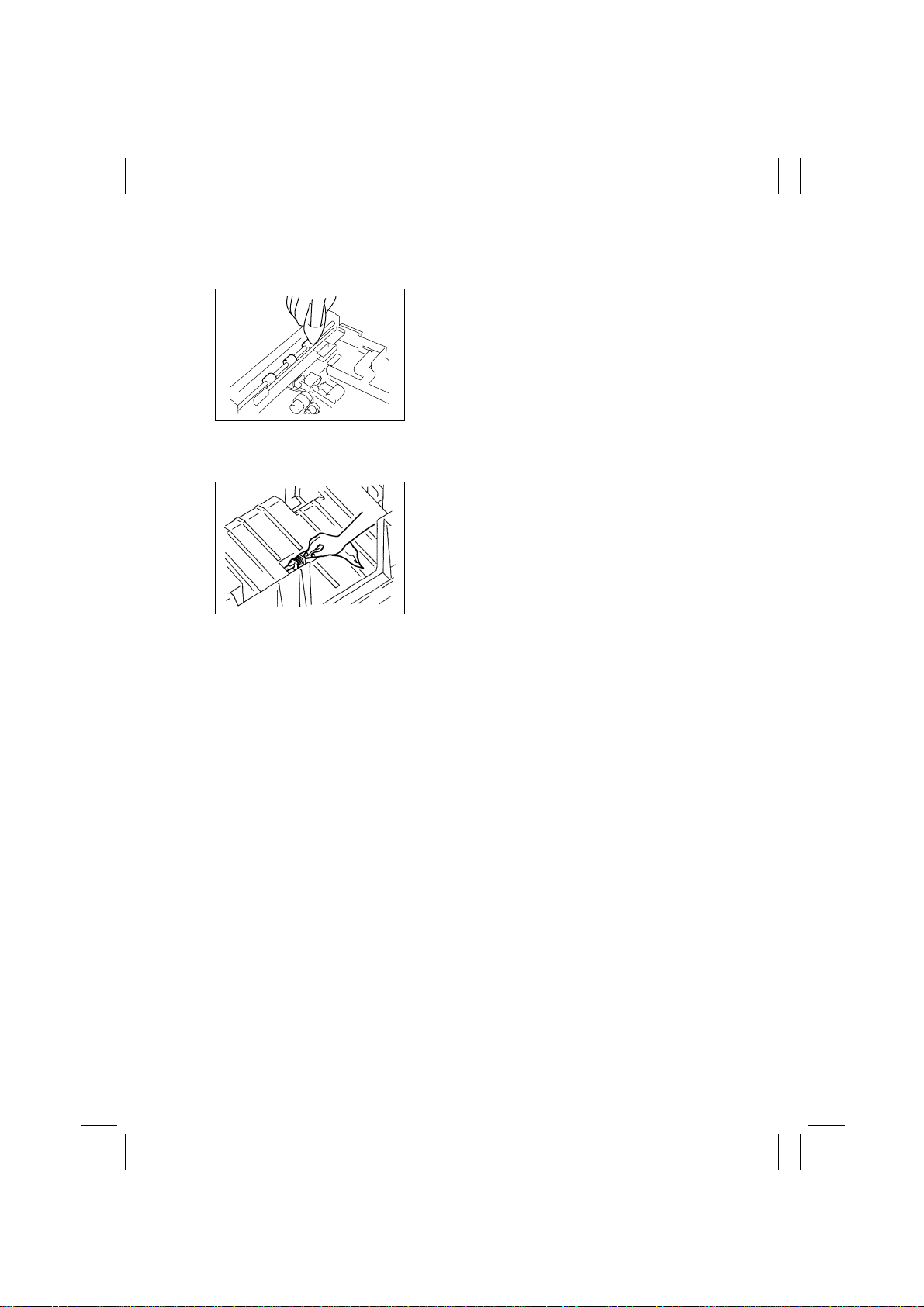
1-7. Cleaning of the Vertical Transport Roller/Rolls
1. Remove the Paper Take-Up Unit.
2. Wipe the surface of the Vertical Transport
Roller/Rolls clean with a soft cloth dampened
with alcohol.
4496D019AA
1-8. Cleaning of the Roll with a Torque Limiter
1. Slide out the LCC.
2. Wipe the surface of the Roll with a Torque Limiter clean with a soft cloth dampened with alcohol.
4496D022AA
D-6
Page 31
FrameMaker Ver.5.5(PC) PF-106 OPTION FOR Di350
98.09.02
2 ADJUSTMENT
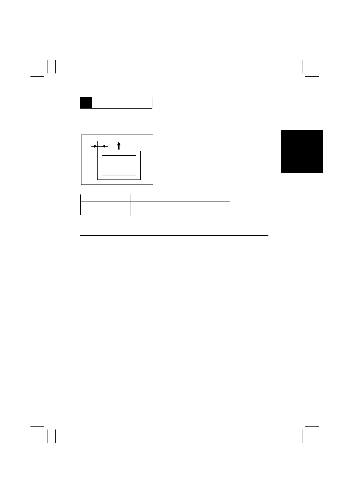
2-1. CD Registration Adjustment (Printer)
Requirement:
A
4486D046AA
Specifications Adjustment Mode Setting Range
A4C 10.0 ±2.0 mm
Letter C 10.0 ±2.0 mm
NOTE:
This adjustment should be made whenever the PH has been replaced with a new one.
Registration CD -4 to +4
Dimension A on the output test print should meet
the following specifications.
For the adjustment procedures, see ADJUSTMENT in the SERVICE MANUAL for the
copier.
D-7
Page 32

FrameMaker Ver.5.5(PC) PF-106 OPTION FOR Di350
98.09.02
MISFEED/MALFUNCTION
DETECTION
Page 33
FrameMaker Ver.5.5(PC) PF-106 OPTION FOR Di350
98.09.02
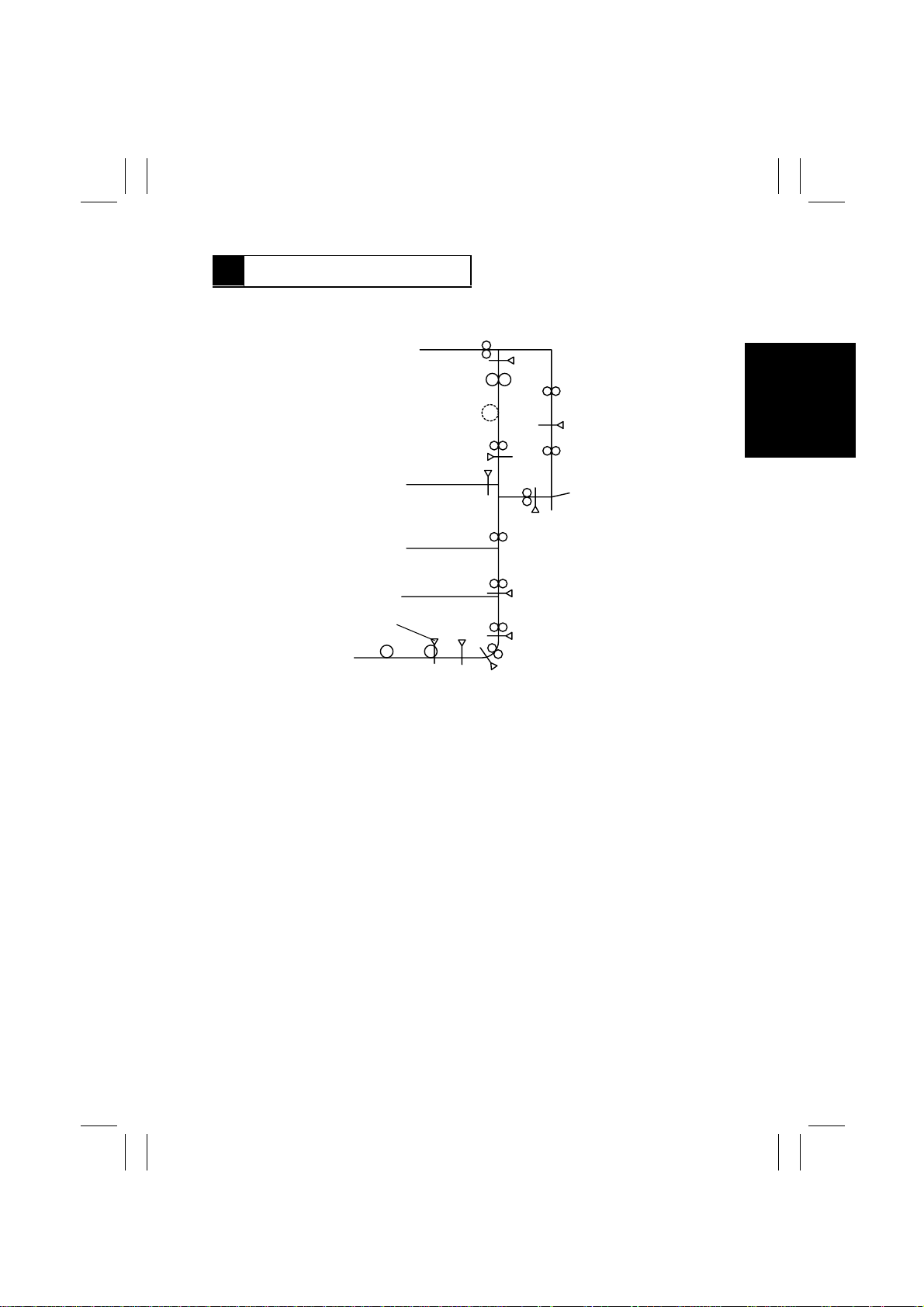
1 MISFEED DETECTION
1-1. Misfeed Detecting Sensor Layout
Synchronizing Roller Sensor PC2
Paper Empty Sensor 1 PPS1
Additional
1st drawer Take-Up Sensor (S3)
Registration Sensor RSEN
T-1
Paper Standby Position Sensor S1
4496M020AA
Page 34

FrameMaker Ver.5.5(PC) PF-106 OPTION FOR Di350
98.09.02
1-2. Types of Misfeed and Misfeed Detection Timings
Type Detection Timing
Paper left The output from Registration Sensor RSEN is blocked (H) when
Lift 1 paper take-up
failure detection
Lift 2 paper take-up
failure detection
Registration Sensor
paper leading edge
detection
Registration Sensor
paper trailing edge
detection
Vertical transport
paper leading edge
detection
Size error detection
the copier Power Switch is turned ON or a misfeed is reset.
Paper Standby Position Sensor S1 is not blocked (H) within a
given period of time after Take-Up Clutch 1 P1CL has been energized.
Paper Empty Sensor 1 PPS1 is not blocked (H) within a given
period of time after Take-Up Clutch 2 P2CL has been energized.
S1 is not blocked (H) within a given period of time after P1CL has
been energized.
RSEN is not blocked (H) within a given period of time after Separator Clutch BCL has been energized (after two paper take-up
retry sequences).
RSEN is not unblocked (L) within a given period of time after Registration Clutch RCL has been energized.
•
LCC only:
Synchronizing Roller Sensor PC2 is not unblocked (H) within a
given period of time after Registration Clutch RCL has been
turned ON.
•
Additional 1st drawer + LCC:
Take-Up Sensor S3 of the additional 1st drawer is not block ed (H)
within a given period of time after Registration Clutch RCL has
been turned ON.
•
LCC only:
The period of time is counted from when Synchronizing Roller
Clutch CL1 is energized to when Synchronizing Roller Sensor
PC2 is blocked (L). The difference between the detected length
and the paper size which has been recognized is more than ±20
mm.
✽
The detection
described on the
right is also made
during a 2-sided
copy cycle.
•
Additional 1st drawer + LCC:
The period of time is counted from when Take-Up Sensor S3 of
the additional 1st drawer is blocked (L) to when it is unblocked
(H). The difference between the detected length and the paper
size which has been recognized is more than ±20 mm.
T-2
Page 35

FrameMaker Ver.5.5(PC) PF-106 OPTION FOR Di350
98.09.02
2 MALFUNCTION DETECTION
Malfunction
Code
C0990 LCC Lift-Up Motor
C0991 Lift 1 ascent motion
C0995 LCC Transport Motor
C0999 Lift 2 ascent motion
C099D Communications
Description Detection Timing
EMOT failure to turn
failure
HMOT failure to turn
failure
error
The overcurrent detection circuit detects an overcurrent condition that lasts for a given period of time
while EMOT remains energized.
Lift-Up Sensor 1 LS1 is not blocked (H) within a
given period of time after EMOT has been energized
(Lift 1 has started moving up).
The HMOT Lock signal is not input for a given period
of time.
Lift-Up Sensor 2 LS2 is not blocked (H) within a
given period of time after EMOT has been energized
(Lift 2 has started moving up).
LCC becomes uncontrollable due to an error in communications between the LCC and copier.
T-3
 Loading...