

Page 1
FrameMaker Ver.5.5E(PC) Di350 GENERAL, MECHANICAL/ELECTRICAL
98.12.18
Di350
MECHANICAL/
ELECTRICAL
Page 2

FrameMaker Ver.5.5E(PC) Di350 GENERAL, MECHANICAL/ELECTRICAL
98.12.18
CONTENTS
1. CROSS-SECTIONAL VIEW ............................................................................M-1
2. COPYING PROCESS ......................................................................................M-2
3. DRIVE SYSTEM ..............................................................................................M-4
4. OPERATING SEQUENCE ..............................................................................M-5
5. CPU OVERRUN MONITOR FUNCTION .........................................................M-8
6. IMAGE STABILIZATION SYSTEM ..................................................................M-9
7. IMAGING CARTRIDGE (I/C) ...........................................................................M-10
7-1. I/C Drive Mechanism ..................................................... ............... ...........M-11
7-2. Identification and Life of I/C .....................................................................M-11
8. PC DRUM ........................................................................................................M-12
9. DRUM CHARGING ..........................................................................................M-13
10. ERASE LAMP ..................................................................................................M-14
11. IR SECTION ....................................................................................................M-15
11-1. Exposure Section: Construction and Function .......................................M-16
11-2. Image Processing Flow ..........................................................................M-17
11-3. Original Size Detection ...........................................................................M-18
11-4. Original Size Detection Timing ...............................................................M-20
11-5. Scanner and 2nd/3rd Mirrors Carriage Moving Mechanism ...................M-21
12. PH SECTION ...................................................................................................M-22
12-1. PH Components .....................................................................................M-23
12-2. Laser Emission Timing (SOS Signal) .....................................................M-24
13. DEVELOPING UNIT ........................................................................................M-25
13-1. Sleeve/Magnet Roller .............................................................................M-26
13-2. Developing Bias ......................................................................................M-27
13-3. ATDC Sensor ......................................................................................... M-28
13-4. Sub Hopper Toner Replenishing Mechanism .........................................M-29
13-5. Sub Hopper Toner Empty Detecting Mechanism ...................................M-30
13-6. Main Hopper Toner Replenishing Mechanism .......................................M-31
13-7. I/C Cooling Fan Motor ............................................................................M-32
13-8. Ozone Fan Motor ....................................................................................M-32
14. PAPER TAKE-UP/FEED SECTION ................................................................M-33
14-1. MP Cassette Paper Lifting Plate .............................................................M-33
14-2. MP Cassette-in-Position Detection .........................................................M-34
14-3. MP Cassette Paper Empty Detection .....................................................M-35
14-4. MP Cassette Paper Size Detection ........................................................M-36
14-5. Paper Take-Up Mechanism ............... ............................................ .........M-37
14-6. Manual Bypass Tray ...............................................................................M-37
14-7. Paper Take-Up Retry Mechanism ........................ ................ ..................M-38
15. SYNCHRONIZING ROLLERS .........................................................................M-39
15-1. Synchronizing Roller Drive Mechanism/Control .....................................M-39
15-2. Paper Dust Remover ..............................................................................M-40
16. IMAGE TRANSFER AND PAPER SEPARATION ...........................................M-41
17. PC DRUM PAPER SEPARATOR FINGERS ...................................................M-42
18. PC DRUM CLEANING .....................................................................................M-43
i
Page 3

FrameMaker Ver.5.5E(PC) Di350 GENERAL, MECHANICAL/ELECTRICAL
98.12.18
19. FUSING UNIT ..................................................................................................M-44
19-1. Drive Mechanism ....................................................................................M-45
19-2. Fusing Rollers Pressure Mechanism .................... ................ ................. .M-45
19-3. Fusing Temperature Control ...................................................................M-46
19-4. CPM Control ........................................................................................... M-47
20. PAPER EXIT UNIT ..........................................................................................M-48
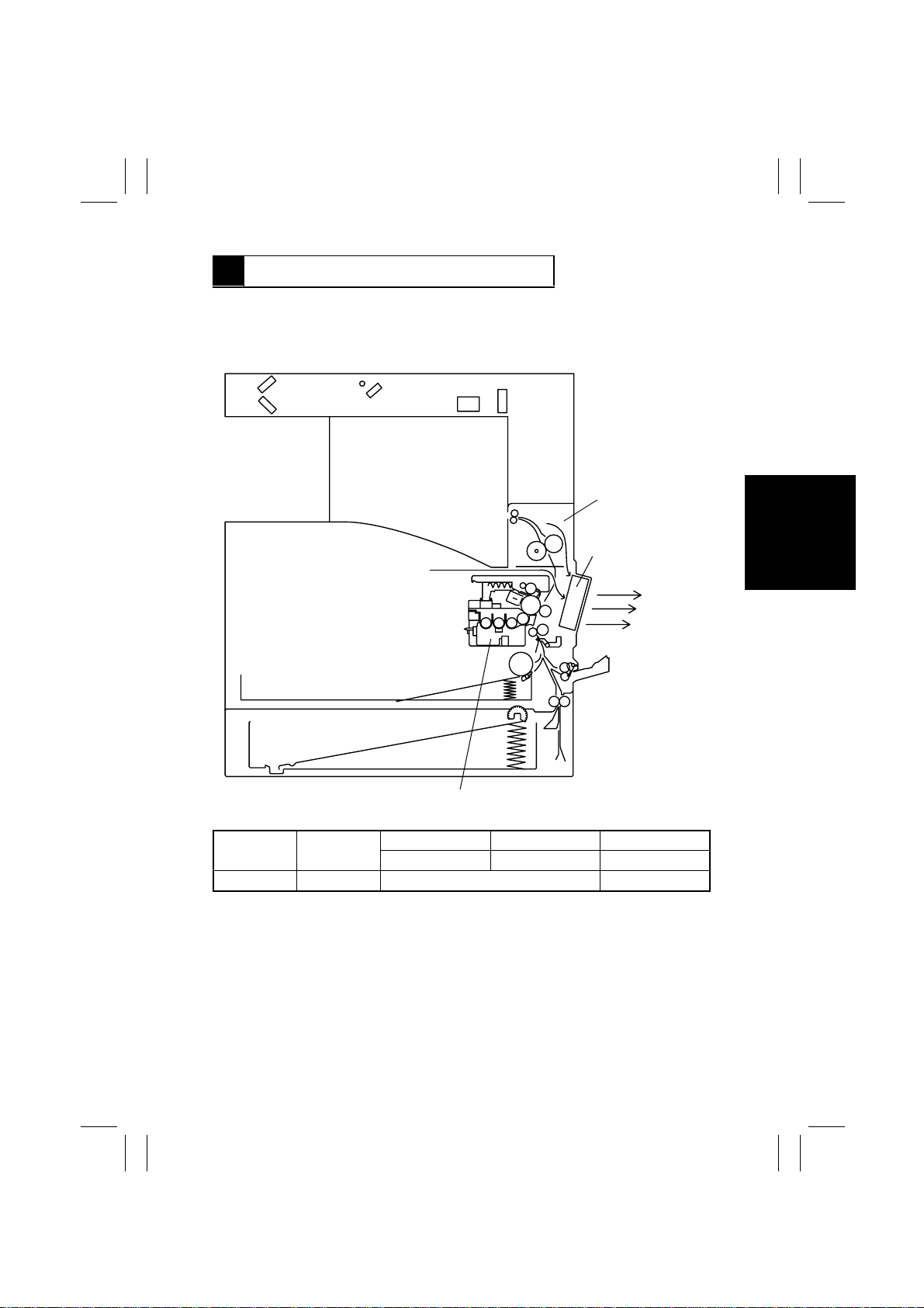
21. FUSING COOLING FAN MOTOR ...................................................................M-49
22. POWER UNIT COOLING FAN MOTOR ..........................................................M-50
ii
Page 4
FrameMaker Ver.5.5E(PC) Di350 GENERAL, MECHANICAL/ELECTRICAL
98.12.18
1171SBM0100A
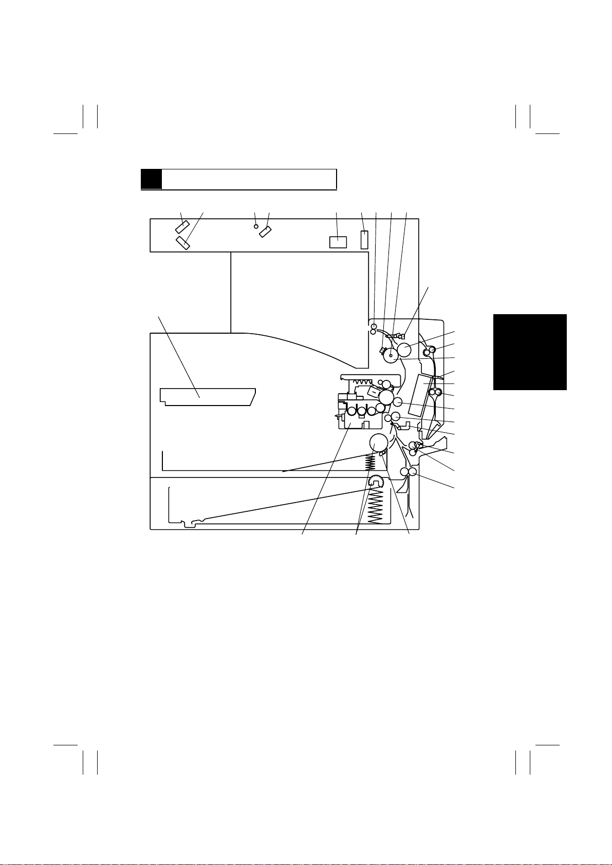
1 CROSS-SECTIONAL VIEW
12 5 6789
26
43
10
11
12
13
14
15
16
17
18
19
20
21
22
1. 2nd Mirror
2. 3rd Mirror
3. Exposure Lamp
4. 1st Mirror
5. Lens
6. CCD Unit
7. Paper Exit Roller
8. Fusing Roller Thermostat (TS1)
9. Fusing Roller Heater Lamp (H1)
10. Paper Exit Sensor (PC3)
11. Right Fusing Roller
12. Duplex Unit Transport Roller 1
13. Left Fusing Roller
14. Duplex Unit Transport Sensor (PI1)
2425
15. Fusing Cooling Fan Motor (M3)
16. Duplex Unit Transport Roller 2
17. Image Transfer Roller
18. Synchronizing Roller
19. Synchronizing Roller Sensor (PC2)
20. Manual Feed P aper Take-Up Sensor
(PC8)
21. Manual Feed Paper Take-Up Roll
22. Vertical Transport Roller
23. Paper Separator Pad
24. Paper Take-Up Roll
25. Imaging Cartridge (I/C)
26. PH Unit
23
M-1
1171M037AA
Page 5
FrameMaker Ver.5.5E(PC) Di350 GENERAL, MECHANICAL/ELECTRICAL
98.12.18
1171SBM0200A
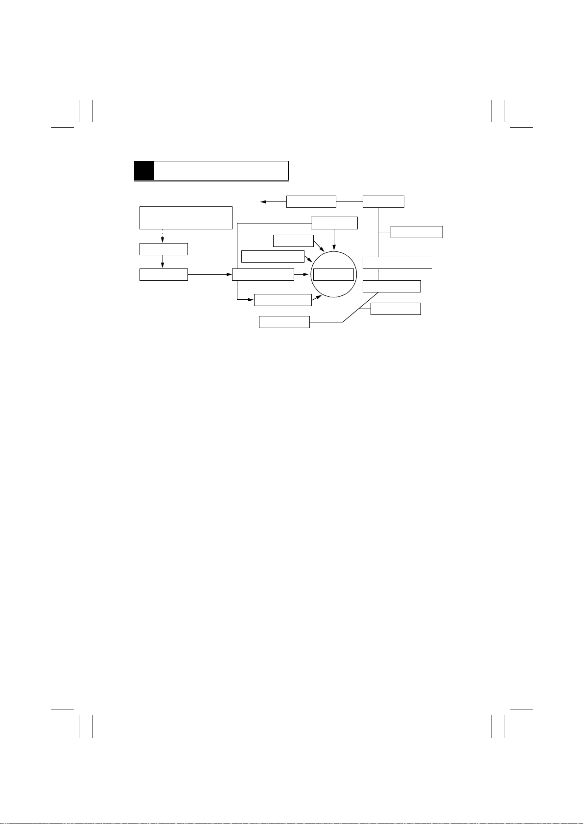
2 COPYING PROCESS
15. Paper Exit 14. Fusing
3. Photoelectric Conversion
Section
4. HGB Board
5. MFB Board 1. PC Drum
2. Drum Charging
6. Laser Exposure
13. Erase
7. Development
8. Paper Feed
1. PC Drum
•
The drum is an aluminum cylinder coated with photosensitive material on which an electrostatic latent image is produced.
2. Drum Charging
•
A scorotron charger employing a comb electrode generates a negative DC charged
layer on the surface of the PC Drum.
3. Photoelectric Conversion Section
•
The Exposure Lamp directs light onto the original. The light reflected off the original is
directed and resized by the mirrors and lens so as to produce a reduced-size image on
the CCD Sensor.
4. HGB Board
•
Converts an electric signal into a corresponding 8-bit digital image signal (A/D conversion), makes various corrections, and outputs the results to the MFB Board.
5. MFB Board
•
Compresses the image data received from the HGB Board, stores it, and uncompresses it.
6. Laser Exposure
•
The laser beam emitted from the LD (laser diode) strik es the surface of the PC Drum,
creating an electrostatic latent image.
7. Development
•
Negatively charged toner adheres to the latent image on the PC Drum surface, creating
a visible image.
8. Paper Feed
•
Feeds sheets of paper from the appropriate paper source.
9. Image Transfer
•
An Image Transfer Roller is used. A positiv e charge applied to the roller causes the visible image on the surface of the PC Drum to transfer onto the front side of the paper.
12. Cleaning
11. Duplex Unit
10. Paper Separation
9. Image Transfer
8. Paper Feed
M-2
Page 6

FrameMaker Ver.5.5E(PC) Di350 GENERAL, MECHANICAL/ELECTRICAL
98.12.18
10. Paper Separation
•
The PC Drum Separator Fingers remove paper from the surface of the PC Drum.
11. Duplex Unit
•
Makes 2-sided copies.
12. Cleaning
•
The Cleaning Blade scrapes residual toner off the surface of the PC Drum and the toner
is recycled back to the Developing Unit.
13. Erase
•
The PC Drum is exposed to light, which effectively removes any residual charge from
the drum surface.
14. Fusing
•
Heat and pressure applied by the Right and Left Fusing Rollers fuse toner on the paper.
15. Paper Exit
•
Feeds paper out of the copier.
M-3
Page 7
FrameMaker Ver.5.5E(PC) Di350 GENERAL, MECHANICAL/ELECTRICAL
98.12.18
1171SBM0300A
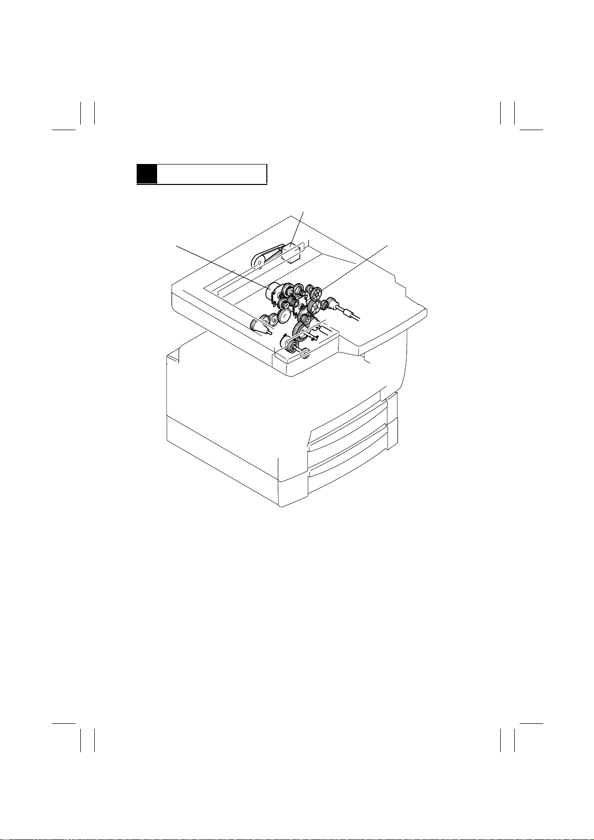
3 DRIVE SYSTEM
A
B
A. Scanner Motor (M5)
Drives the Scanner and 2nd/3rd Mirrors Carriage.
B. I/C Motor (M1)
Drives the I/C Unit.
C. Main Motor (M2)
Drives the Paper Take-Up Roll, Manual Feed Paper Take-Up Roll, Synchronizing
Roller, Image Transfer Roller, and Fusing Unit.
C
1171M024AB
M-4
Page 8

FrameMaker Ver.5.5E(PC) Di350 GENERAL, MECHANICAL/ELECTRICAL
98.12.18
1171SBM0400A
4 OPERATING SEQUENCE
A The power cord is plugged into the power outlet.
ON
The Power Supply Unit outputs DC24V for the Dehumidifying Heater (option).
B The Power Switch is turned ON.
ON
DC voltage output
ON
Control panel display
Approx.
560 msec.
C The warming-up cycle is completed.
ON
Main Motor
Power Unit Cooling Fan Motor turns
at full speed.
ON
Developing bias (DC)
Approx.
100 msec.
ON
Fusing Roller Heater Lamp
Approx. 20 sec.
ON
I/C Motor
ON
Image transfer output: - voltage
Approx.
700 msec.
ON
OFF
Predrive stops
Power Unit Cooling Fan Motor turns
at half speed.
Image transfer output:
+ voltage
Approx.
400 msec.
Approx.
400 msec.
Normal T/C
Abnormal T/C: approx. 31 sec.
ON
Image transfer output:
- voltage
ON
Image transfer output:
- voltage
OFF.
I/C Motor
Approx.
400 msec.
M-5
Approx.
400 msec.
T/C ratio is checked for abnormality
for approx. 28 sec.
ON
OFF
Image transfer output
Approx.
15 min.
Image transfer output:
+ voltage
OFF
Developing bias
(DC)
Page 9
FrameMaker Ver.5.5E(PC) Di350 GENERAL, MECHANICAL/ELECTRICAL
98.12.18
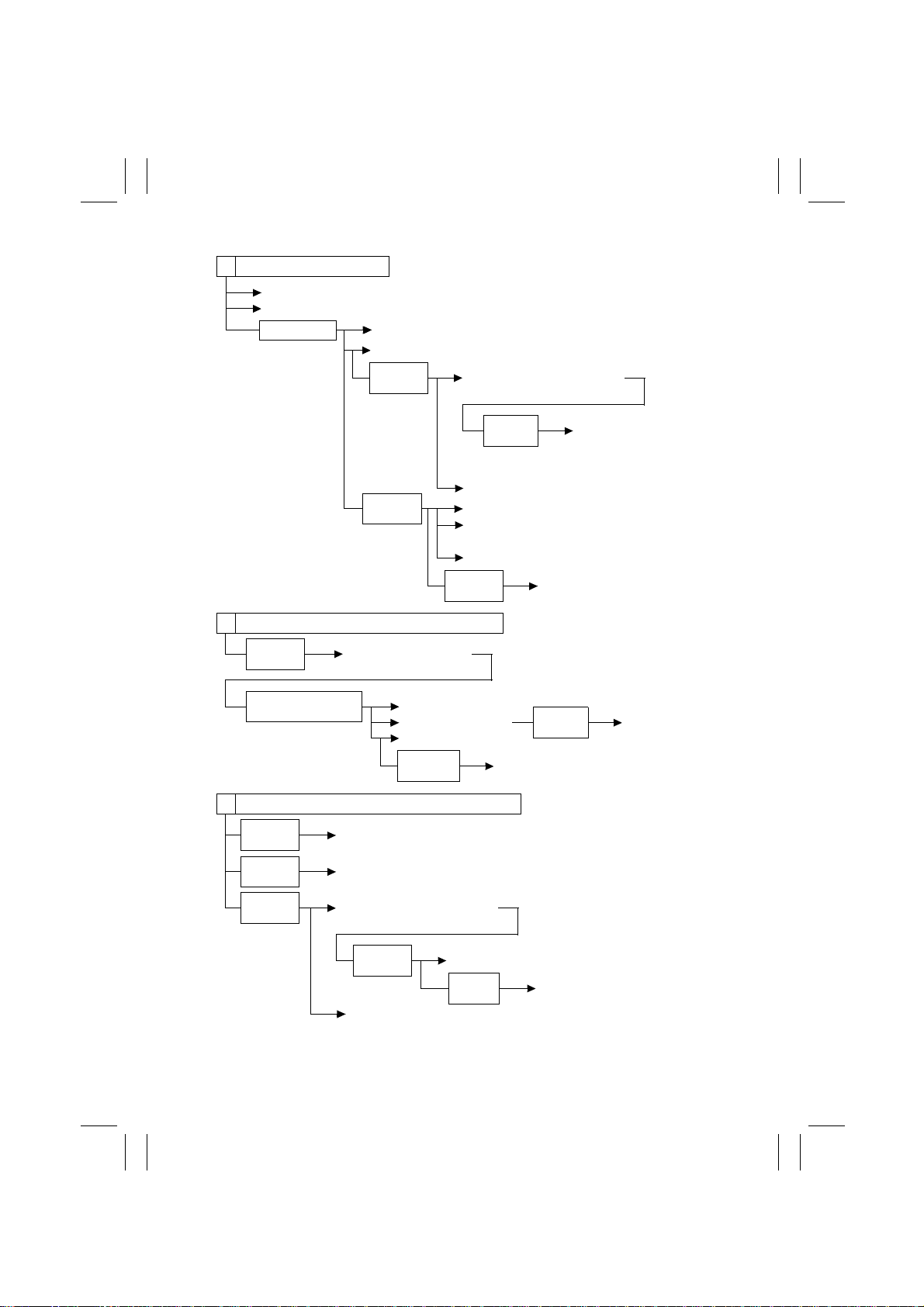
D The Start key is pressed.
ON
Polygon Motor
ON
Fusing Cooling Fan Motor
Approx. 6 sec.
ON
Laser
ON
Developing bias (DC)
Approx.
100 msec.
ON
Image transfer output: - voltage
Approx.
1.1 sec.
ON
I/C Motor
Approx.
140 msec.
ON
Main Motor
The Power Unit Cooling Fan Motor turns at full
speed.
The Ozone Fan Motor turns at full speed.
Approx.
700 msec.
E The Synchronizing Roller Sensor is activated.
Approx.
110 msec.
VSYNC signal ON:
approx. 50 msec. later
OFF
Paper Take-Up Solenoid
ON
ON
ON
Paper Take-Up Solenoid
Synchronizing Clutch
Developing bias (AC)
Approx.
160 msec.
ON
F The Synchronizing Roller Sensor is deactivated.
Approx.
130 msec.
Approx.
170 msec.
Approx.
320 msec.
OFF
Synchronizing Clutch
OFF
Developing bias (AC)
ON
Image transfer output: - voltage
ON
Image transfer current
value for non-printing
timing between sheets of
paper
ON
Paper Take-Up Solenoid
Approx.
90 msec.
Image transfer current value for printing
OFF
Paper Ta ke-Up
Solenoid
OFF
Approx.
650 msec.
Laser
OFF
I/C Motor
Approx.
15 min.
M-6
OFF
Developing bias (DC)
Page 10

FrameMaker Ver.5.5E(PC) Di350 GENERAL, MECHANICAL/ELECTRICAL
98.12.18
G The Paper Exit Sensor is deactivated.
Approx.
680 msec.
OFF
OFF
Main Motor
The Power Unit Cooling Fan Motor turns at half speed.
Polygon Motor
Approx. 10 sec.
Approx. 20 sec.
OFF
Ozone Fan Motor
OFF
Fusing Cooling Fan Motor
M-7
Page 11

FrameMaker Ver.5.5E(PC) Di350 GENERAL, MECHANICAL/ELECTRICAL
98.12.18
1171SBM0500A
5 CPU OVERRUN MONITOR FUNCTION
•
CPU Overrun Monitor Function (Watchdog Function)
The watchdog function is a self-monitoring function that determines whether any of the
CPUs mounted on the control board overrun.
•
If this function detects that a CPU overruns, the copier automatically resets the CPU,
thereby restarting the logic circuit and mechanism.
•
Even if a copier CPU operates erratically due to electrical noise, therefore, the copier is
able to recover from the faulty condition so that the number of visits made by the Tech.
Rep. for CPU overrun can be minimized.
•
Processing performed during watchdog function:
If a faulty condition is detected, the copier resets the CPU and performs a restart
sequence. Since this sequence of operations is performed even during a copy cycle, the
copier detects a sheet or sheets of paper left inside it as a misfeed while it is being
restarted.
M-8
Page 12
FrameMaker Ver.5.5E(PC) Di350 GENERAL, MECHANICAL/ELECTRICAL
98.12.18
1171SBM0600A
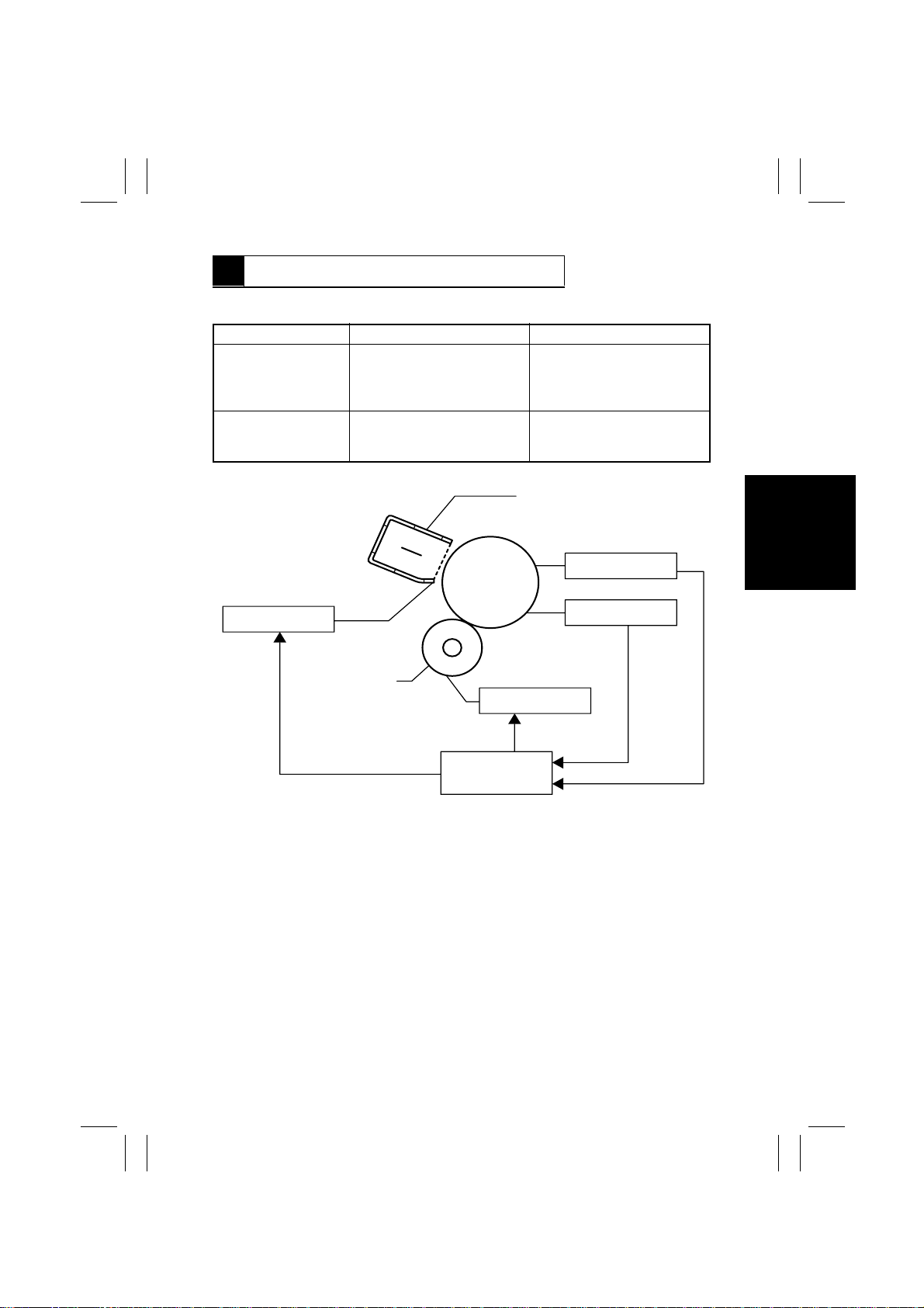
6 IMAGE STABILIZATION SYSTEM
•
The following image stabilization controls are provided to ensure stabilized copy image.
Item Purpose Control
PC Drum temperature
correction
PC Drum deterioration
correction
Grid Voltage: (Vg)
To compensate for any change
in ID due to changing PC Drum
temperatures.
To compensate for degraded
sensitivity caused by a deteriorating PC Drum.
PC Drum
The I/C Thermistor is used to
detect temperature and,
according to the detected temperature, Vg/Vb is corrected.
Corrects Vg according to the
period of time during which the
PC Drum has turned.
PC Drum Charge Corona
I/C Thermistor (TH2)
PC Drum Revolution
Counter
Sleeve/
Magnet Roller
Developing Bias: (Vb)
CPU
1171M028AA
M-9
Page 13
FrameMaker Ver.5.5E(PC) Di350 GENERAL, MECHANICAL/ELECTRICAL
98.12.18
1171SBM0700A
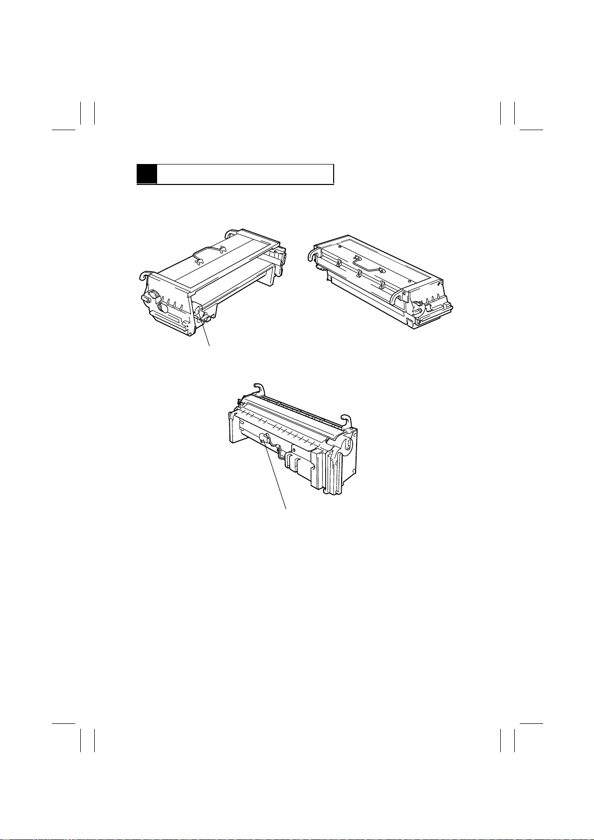
7 IMAGING CARTRIDGE (I/C)
•
This copier employs an Imaging Cartridge (“I/C” in this manual) that contains a PC Drum,
PC Drum Charge Corona, Developing Unit, and Cleaning Unit as one unit.
Toner Supply Port
1171M002AA
ATDC Sensor (E1)
1171M001AA
1171M003AA
M-10
Page 14
FrameMaker Ver.5.5E(PC) Di350 GENERAL, MECHANICAL/ELECTRICAL
98.12.18
1171SBM0701A
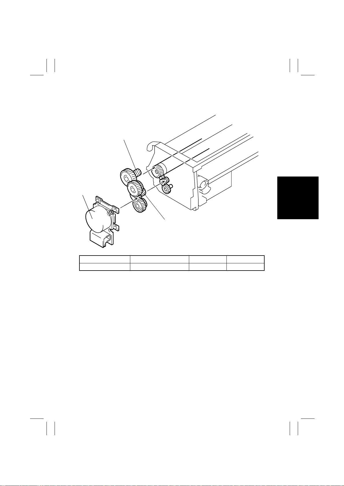
7-1. I/C Drive Mechanism
•
Drive from the I/C Motor is transmitted via a gear train to the PC Drum and Hopper.
PC Drum Drive Gear
I/C Motor (M1)
Hopper Drive Gear
1171M004AA
Electrical Component Control Signal ON OFF
M1 PJ16A-3 L H
1171SBM0702A
7-2. Identification and Life of I/C
•
When the Start key is pressed or the Side Cover is opened and closed, the copier determines whether the I/C is new or one which has been used previously.
•
The copier monitors the I/C life by storing in memory the period of time during which the
PC Drum has turned. The data is cleared when a new I/C is installed in the copier.
M-11
Page 15
FrameMaker Ver.5.5E(PC) Di350 GENERAL, MECHANICAL/ELECTRICAL
98.12.18
1171SBM0800A
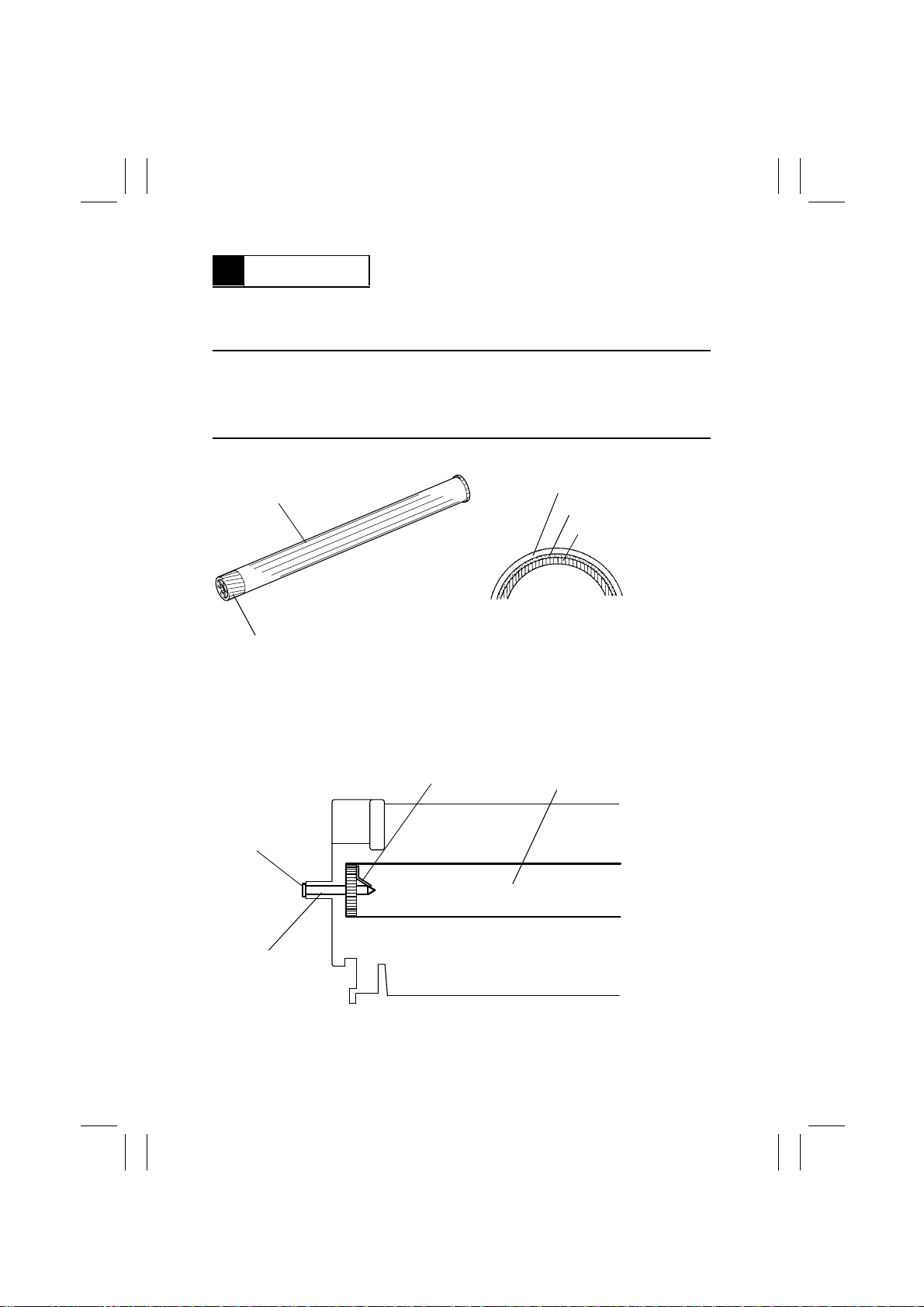
8 PC DRUM
•
The PC Drum used in this copier is the organic photoconductor (OPC) type.
The drum consists of an aluminum base coated with a charge generation la yer and a
charge transport layer.
Handling Precautions
Prolonged exposure to light can cause the photoconductor surface of the drum to suffer
light fatigue, resulting in a loss of photosensitivity. If the I/C is removed from the copier, it
should be wrapped in a soft, clean, opaque cloth or other protective covering to prevent
exposure to light.
PC Drum Cross-Section
PC Drum
Charge Transport Layer
Charge Generation Layer
Aluminum Base
1139M007AA1167M007AA
Gear
•
Grounding of the PC Drum
The PC Drum ground point is located inside and at the front end of the I/C as viewed
from the front of the copier and in constant contact with the Drum Holding Shaft. When
the I/C is installed in the copier, the Drum Holding Shaft contacts the ground point. This
provides for assured grounding of the PC Drum through the ground plate in the rear to
the frame of the copier.
Ground Point
Ground Plate
Shaft
PC Drum
1171M005AA
M-12
Page 16
FrameMaker Ver.5.5E(PC) Di350 GENERAL, MECHANICAL/ELECTRICAL
98.12.18
1171SBM0900A
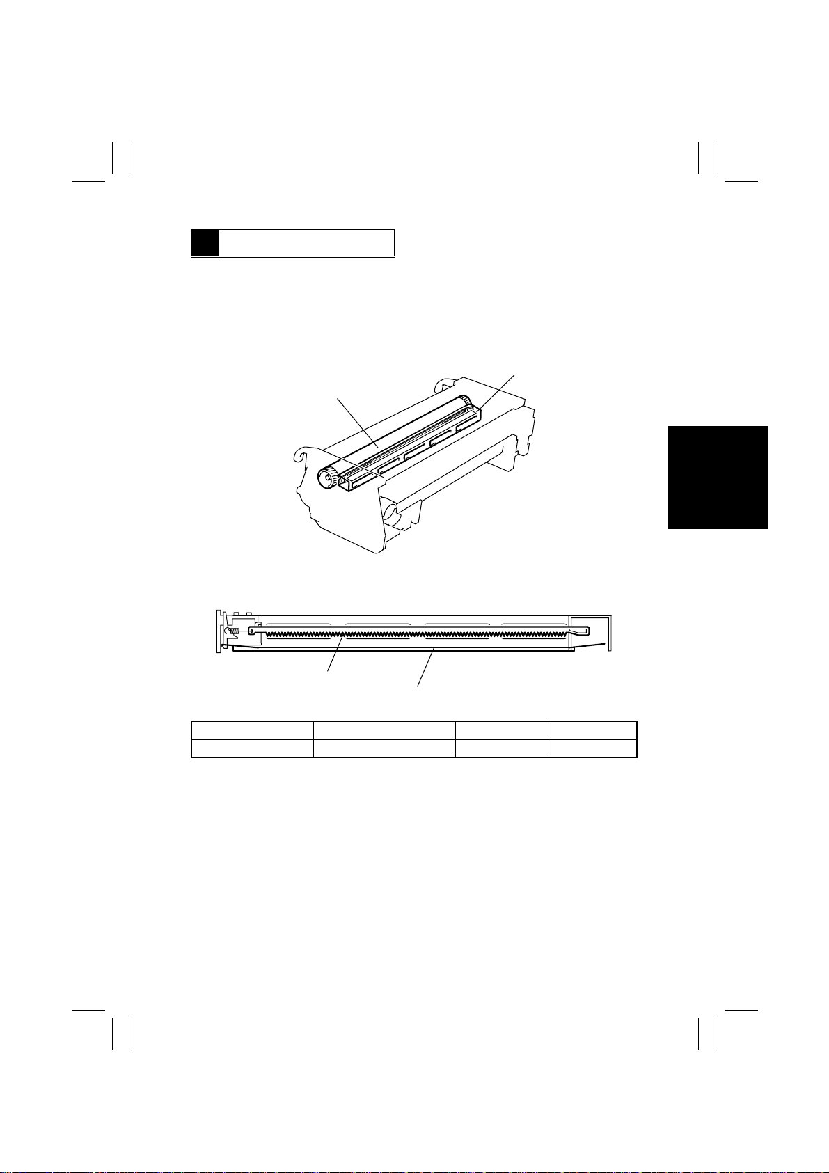
9 DRUM CHARGING
•
A scorotron charger system generates a negative DC corona discharge onto the PC
Drum surface. The grid mesh ensures uniform charging.
•
The grid voltage (Vg) applied to the grid mesh is controlled by the constant voltage circuitry within the High Voltage Unit. It is varied through image stabilization control.
•
To restrict ozone production, the copier uses a PC Drum Charge Corona with a comb
electrode.
PC Drum Charge Corona
PC Drum
1171M006AB
1171M008AC
Comb Electrode
Grid Mesh
Electrical Component Control Signal ON OFF
Drum charging output PJ14A-3A L H
M-13
Page 17
FrameMaker Ver.5.5E(PC) Di350 GENERAL, MECHANICAL/ELECTRICAL
98.12.18
1171SBM1000A
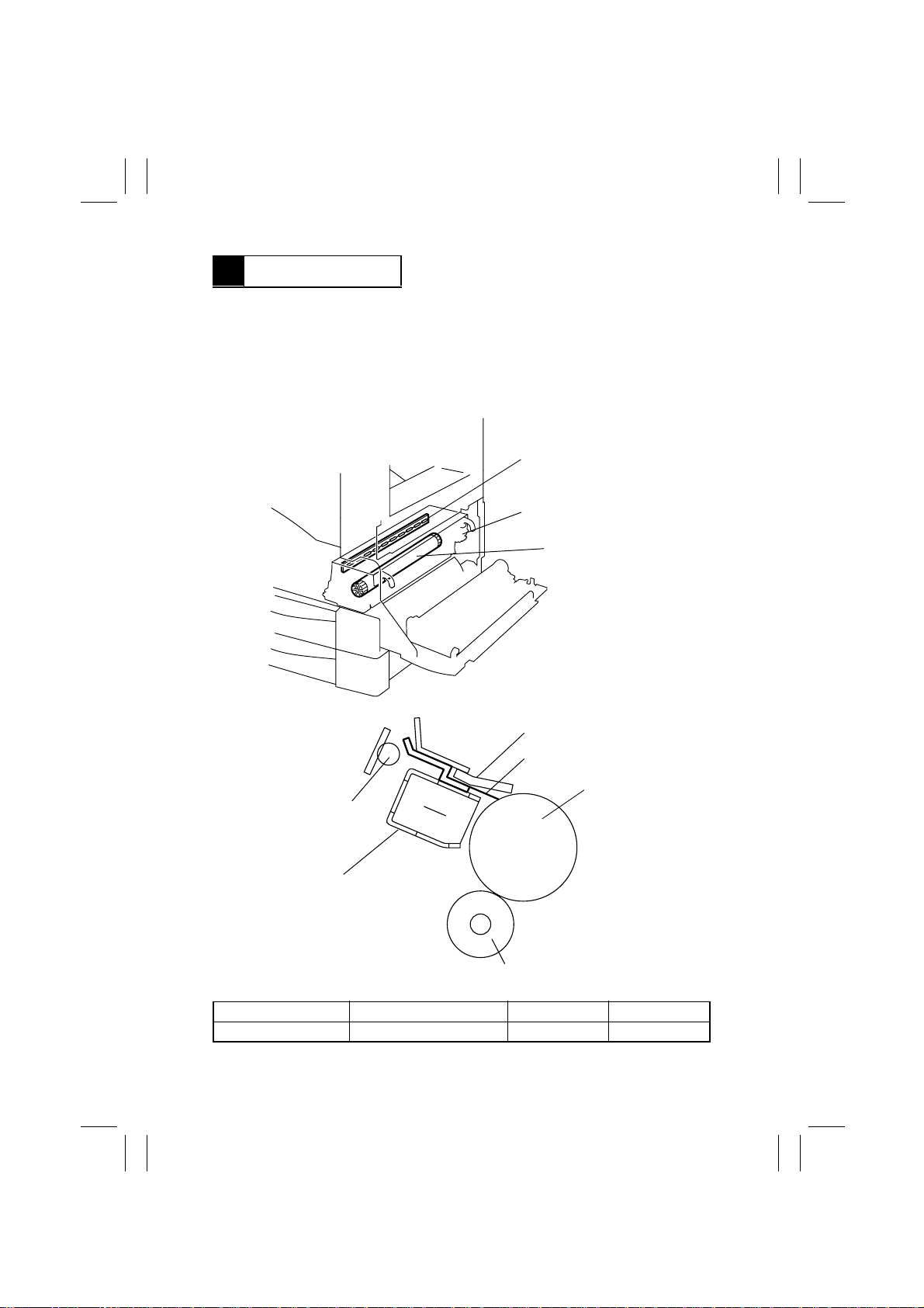
10 ERASE LAMP
•
Any potential remaining on the surface of the PC Drum is neutralized by both light from
the Erase Lamp and a DC negative voltage applied by the Charge Neutralizing Sheet.
•
The Charge Neutralizing Sheet applies a negative charge on the surface of the PC Drum
which is positively charged by the Image Transfer Roller. A volt age of -820V is applied to
the Charge Neutralizing Sheet from the High Voltage Unit. The Erase Lamp then illuminates the surface of the PC Drum to further neutralize it.
•
The Erase Lamp consists of ten tungsten lamps.
Erase Lamp (LA1)
I/C
PC Drum
1171M009AD
Cleaning Blade
Charge Neutralizing Sheet
PC Drum
Erase Lamp (LA1)
PC Drum Charge Corona
1171M010AD
Sleeve/Magnet Roller
Electrical Component Control Signal All lamps ON Standby ON
LA1 PJ11A-6A H L
M-14
Page 18
FrameMaker Ver.5.5E(PC) Di350 GENERAL, MECHANICAL/ELECTRICAL
98.12.18
1171SBM1100A
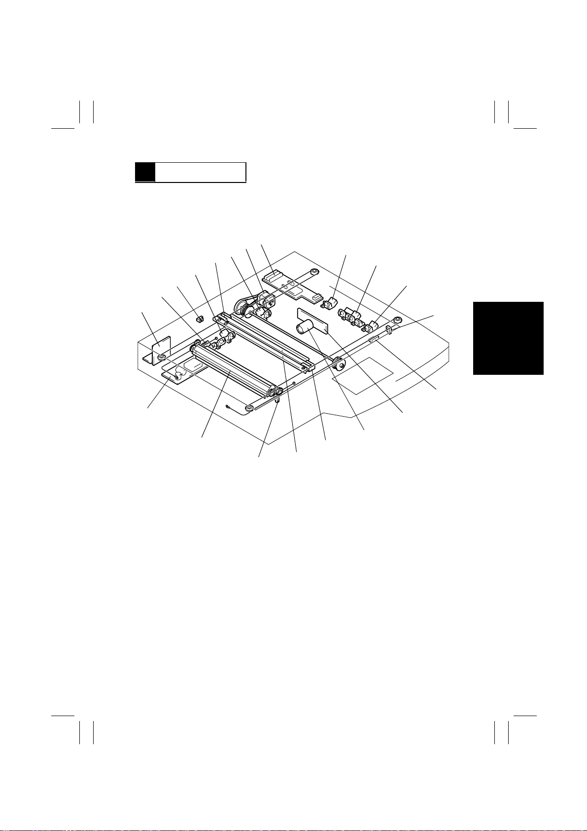
11 IR SECTION
•
Light reflected from the original passes through three mirrors and a lens to form a
reduced image on the CCD Sensor as the Scanner is moved by the Scanner Motor. The
CCD sensor converts the light pattern (image data) into an electrical image signal.
•
The electrical image signal is then output to the MFB Board.
8
7
6
5
4
3
2
1
9
10
11
12
20
19
18
1. BCR Board (BCR)
2. Original Size Detecting Sensor 5 (UN8)
3. Original Cover Detecting Sensor (PC14)
4. Original Size Detecting Sensor 4 (UN7)
5. Exposure Lamp (LA2)
6. Original Size Detecting Sensor 6 (UN9)
7. Scanner Motor (M5)
8. HGB Board (HGB)
9. Original Size Detecting Sensor 1 (UN4)
10. Original Size Detecting Sensor 2 (UN5)
11. Original Size Detecting Sensor 3 (UN6)
14
15
16
17
12. Scanner Home Position Sensor 1
(PC12)
13. Size Reset Switch (S5)
14. CCD Board (CCD)
15. Lens
16. Scanner
17. 1st Mirror
18. Scanner Home Position Sensor 2
(PC13)
19. 2nd/3rd Mirrors Carriage
20. Inverter Board (INV)
1167M110AD
13
M-15
Page 19
FrameMaker Ver.5.5E(PC) Di350 GENERAL, MECHANICAL/ELECTRICAL
98.12.18
1171SBM1101A
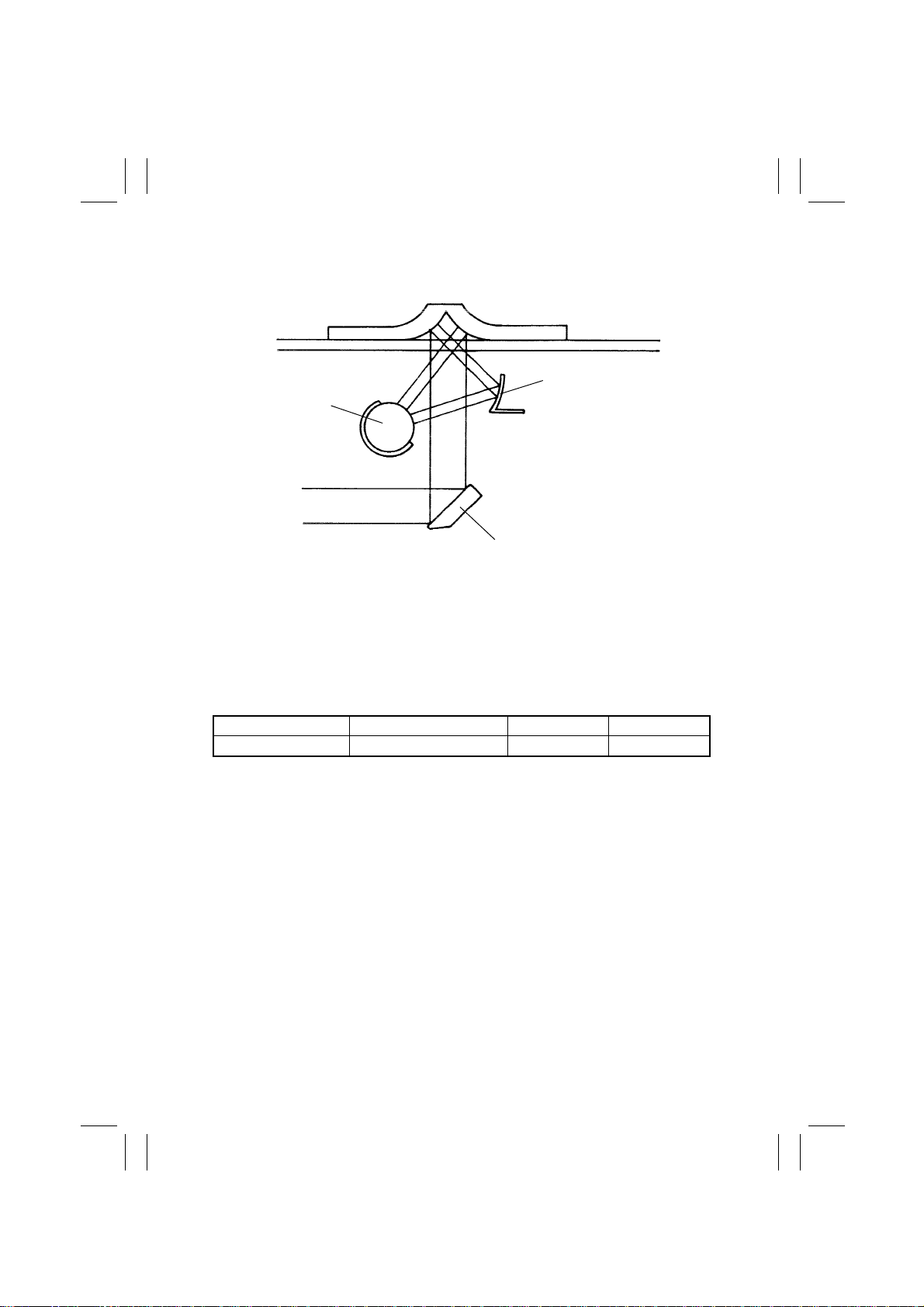
11-1. Exposure Section: Construction and Function
1. Auxiliary Reflector
2. Exposure Lamp
3. 1st Mirror
1. Auxiliary Reflector
When a book or other bound original is copied, the paper in the area near the binding
generally fails to come flush against the glass, so that the copy of these areas is generally too dark. The Auxiliary Reflector reduces this problem by reflecting light from the
Exposure Lamp onto these areas of the original.
2. Exposure Lamp
A fluorescent lamp is used to illuminate the original.
3. 1st Mirror
Directs the reflected light from the original to the 2nd Mirror.
Electrical Component Control Signal ON OFF
LA2 CN13BCR-1 L H
1167M089AA
M-16
Page 20
FrameMaker Ver.5.5E(PC) Di350 GENERAL, MECHANICAL/ELECTRICAL
98.12.18
1171SBM1102A
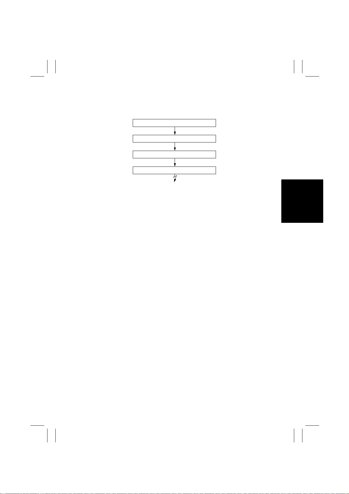
11-2. Image Processing Flow
•
Image processing is made up of the following blocks.
1. Photoelectric Conversion (CCD Sensor)
2. HGB Board
Transmitted over an optical cable.
3. MFB Board
4. PH (Laser Emission)
1. Photoelectric Conversion (CCD Sensor)
•
Light reflected off the original is received through mirrors and lens by the CCD Sensor
which, in turn, outputs the corresponding data to the HGB Board.
2. HGB Board
•
After converting the data received from the CCD to an analog signal, the board converts
it to 8-bit image data (A/D conversion). It further makes various corrections and outputs
the resultant image data to the MFB Board over an optical cable.
3. MFB Board
•
This board compresses the image data received from the HGB Board, stores it, and
uncompresses it.
•
The image memory has a standard capacity of 16MB and can be expanded up to 64MB
(optional).
4. PH
•
Emits a laser beam according to the image data provided by the MFB Board to expose
the surface of the PC Drum.
M-17
Page 21
FrameMaker Ver.5.5E(PC) Di350 GENERAL, MECHANICAL/ELECTRICAL
98.12.18
1171SBM1103A
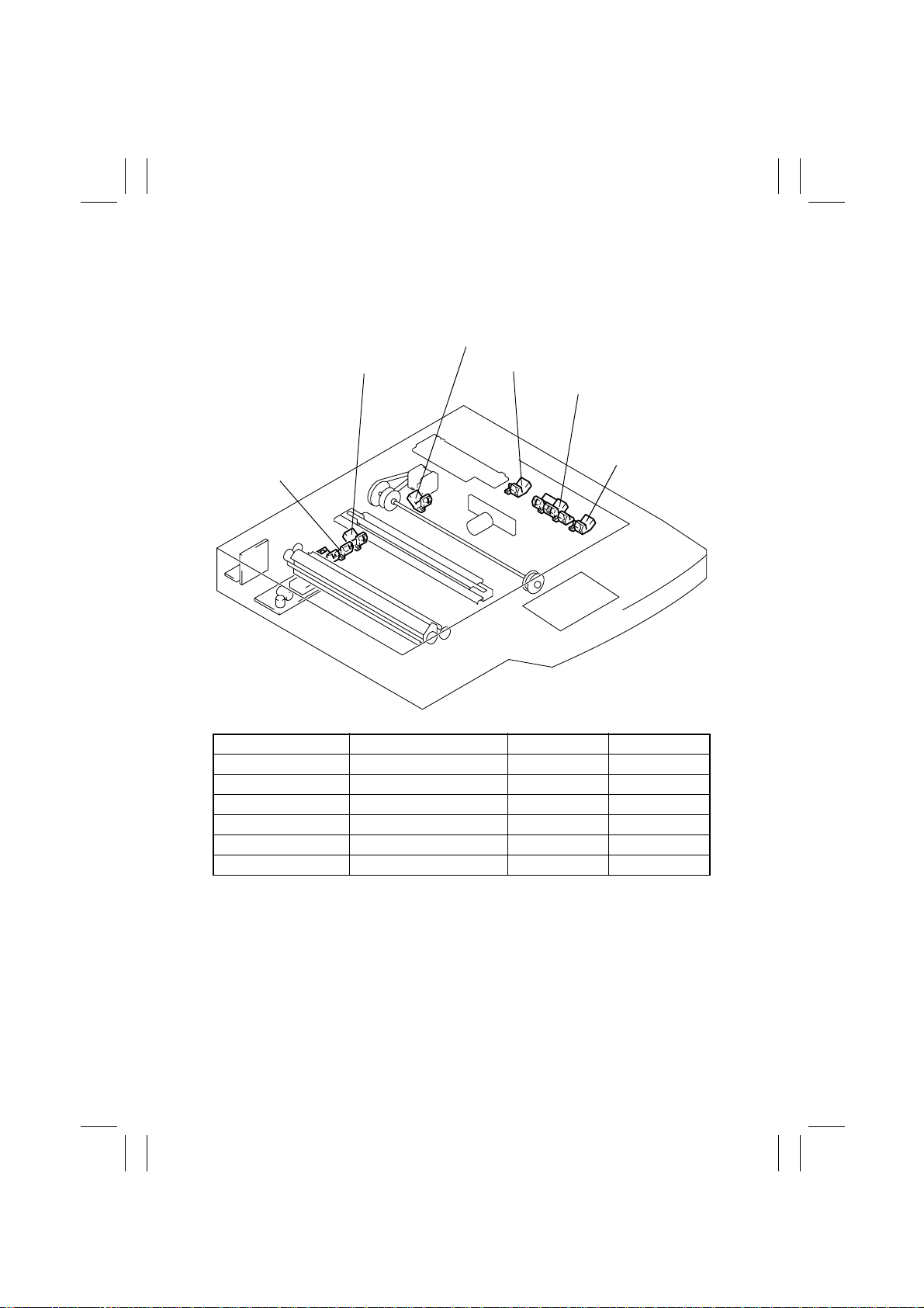
11-3. Original Size Detection
•
When the copier is in Auto Paper or Auto Size, the sensors mounted in the IR receive
light reflected off the original to allow the copier to determine the original size.
Original Size Detecting Sensor 6 (UN9)
Original Size Detecting Sensor 4
(UN7)
Original Size
Detecting Sensor
5 (UN8)
Original Size Detecting Sensor 1 (UN4)
Original Size Detecting Sensor 2
(UN5)
Original Size
Detecting Sensor
3 (UN6)
1171M025AD
Electrical Component Control Signal Blocked Unblocked
UN4 CN4BCR-4 L H
UN5 CN5BCR-7 L H
UN6 CN11HGB-4 L H
UN7 CN6BCR-4 L H
UN8 CN9HGB-1 L H
UN9 CN8BCR-4 L H
M-18
Page 22
FrameMaker Ver.5.5E(PC) Di350 GENERAL, MECHANICAL/ELECTRICAL
98.12.18
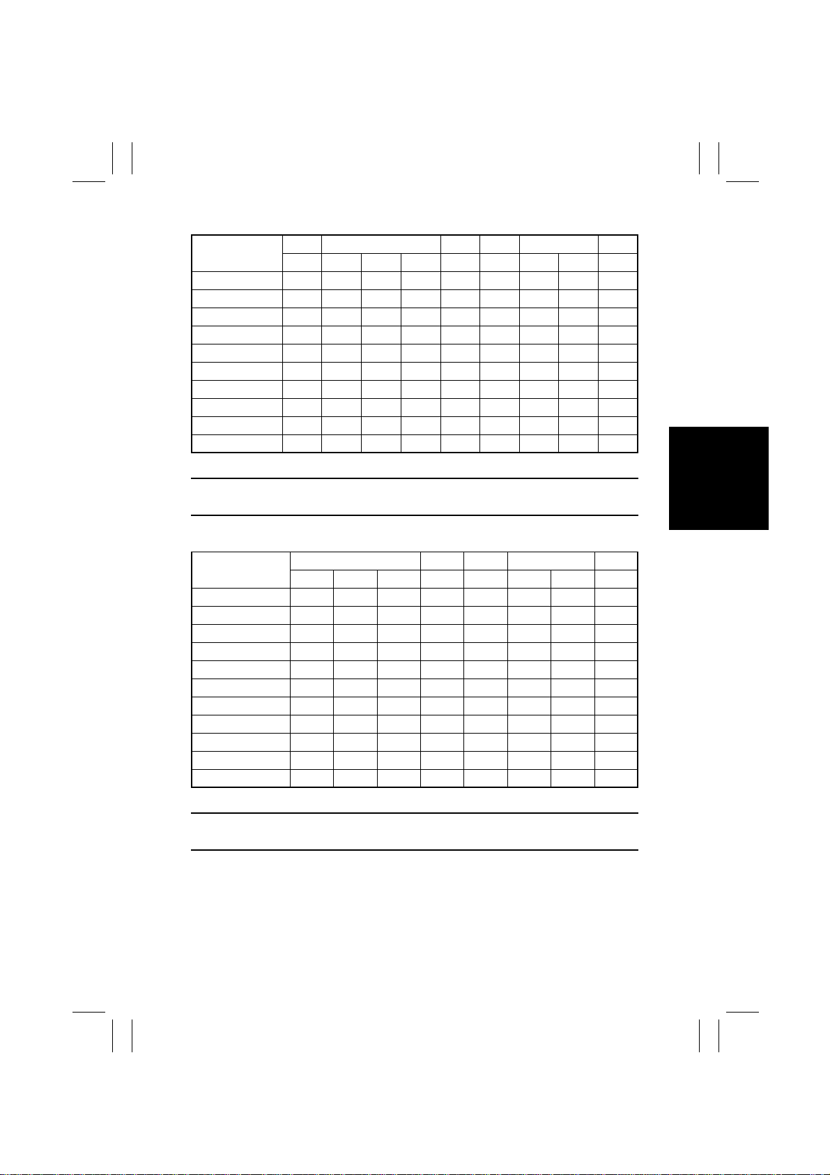
<Original Size Identification: Metric Areas>
Original Size
11” × 17”
A3L
A4L
A4C
A5L
B4L
FLS
Letter L
Letter C
Legal
❍
: Detected by sensor; L: Lengthwise; C: Crosswise
UN4 UN5 UN6 UN7 UN8 UN9
S1 S2 S3 S4 S5 S6 S7 S8 S9
❍❍❍❍ ❍❍❍❍
❍❍❍❍❍❍❍❍❍
❍❍ ❍ ❍
❍❍❍❍❍ ❍
❍❍❍ ❍❍❍❍
❍❍ ❍❍ ❍
❍❍ ❍
❍❍❍❍ ❍
❍❍ ❍❍❍❍
NOTE
UN4, UN6 and UN8 are options.
❍
<Original Size Identification: Inch Areas>
Original Size
11” × 17”
A3L
A4L
A4C
B4L
5-1/2” × 8-1/2”L
FLS
B5C
Letter L
Letter C
Legal
❍
: Detected by sensor; L: Lengthwise; C: Crosswise
UN5 UN6 UN7 UN8 UN9
S2 S3 S4 S5 S6 S7 S8 S9
❍❍❍ ❍❍❍❍
❍❍❍❍❍❍❍❍
❍❍❍
❍❍❍❍ ❍
❍❍ ❍❍❍❍
❍❍❍❍
❍❍ ❍
❍❍
❍❍❍ ❍
❍ ❍❍❍❍
NOTE
UN6, UN8 and UN9 are options.
❍
M-19
Page 23
FrameMaker Ver.5.5E(PC) Di350 GENERAL, MECHANICAL/ELECTRICAL
98.12.18
1171SBM1104A
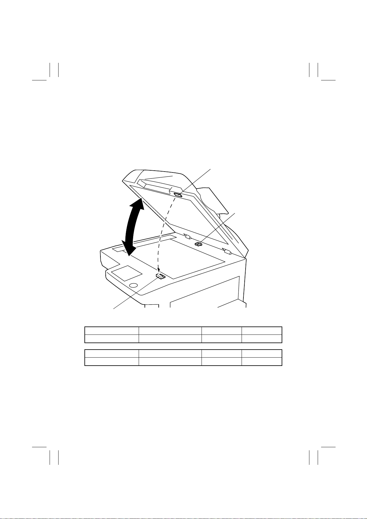
11-4. Original Size Detection Timing
The copier CPU affirms and resets the readings of the original size at the following timings.
•
Takes size readings:
When the Original Cover Detecting Sensor is deactivated.
•
Affirms size readings:
When the Start key is pressed with the Original Cover Detecting Sensor activated or the
Size Reset Switch deactuated.
•
Resets size readings:
When the Size Reset Switch is deactuated.
Magnet
Original Cover
Detecting Sensor
(PC14)
Size Reset Switch (S5)
Electrical Component Control Signal ON OFF
S5 CN9BCR-2 L H
Electrical Component Control Signal Unblocked Blocked
PC14 CN10BCR-2 L H
1167M113AB
M-20
Page 24
FrameMaker Ver.5.5E(PC) Di350 GENERAL, MECHANICAL/ELECTRICAL
98.12.18
1171SBM1105A
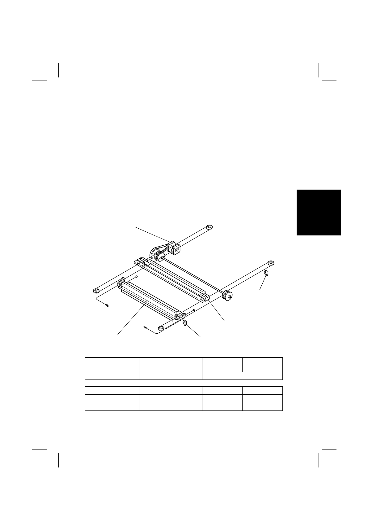
11-5. Scanner and 2nd/3rd Mirrors Carriage Moving Mechanism
<Scanner>
•
During a scan, the Scanner projects an even amount of light from the Exposure Lamp
onto the entire surface of the original. The light is reflected from the original to the 1st
Mirror of the scanner and then to the 2nd and 3rd Mirrors.
•
The Scanner is driven by the Scanner Motor and front and rear Scanner Drive Cables.
•
Scanner speed is determined by the set zoom ratio in reference to the full size mode.
•
The Scanner is at home position when Scanner Home Position Sensor 1 is blocked. This
position serves as the reference for the scan motion.
•
Scanner Home Position Sensor 2 determines the home position of the Scanner when
AF-7 is used.
<2nd/3rd Mirrors Carriage>
•
The 2nd and 3rd Mirrors are mounted to their holder at right angles to each other. They
direct the light reflected off the 1st Mirror through the lens to the CCD.
•
The 2nd/3rd Mirrors Carriage is also moved by the Scanner Drive Cables and pulleys
driven by the Scanner Motor. It travels at a speed half that of the Scanner, thereby keeping constant the optical path length between the Original Glass and lens.
Scanner Motor (M5)
Scanner Home
Position Sensor 1
(PC12)
Scanner
2nd/3rd Mirrors Carriage
Electrical Component Control Signal
M5 CN3BCR-1~3 Pulse output
Electrical Component Control Signal Blocked Unblocked
PC12 CN11BCR-1 L H
PC13 CN12BCR-1 L H
Scanner Home Position
Sensor 2 (PC13)
Forward
Rotation
1167M112AA
Backward
Rotation
M-21
Page 25
FrameMaker Ver.5.5E(PC) Di350 GENERAL, MECHANICAL/ELECTRICAL
98.12.18
1171SBM1200A
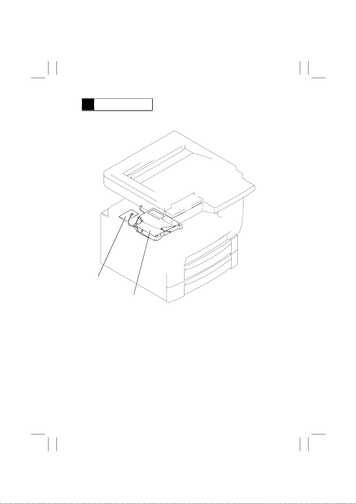
12 PH SECTION
•
Based on the image data output from the MFB Board, the LD (laser diode) is activated
and the corresponding light strikes the surface of the PC Drum.
Polygon Motor Drive
Board (UN3)
PH Unit
1171M035AA
M-22
Page 26
FrameMaker Ver.5.5E(PC) Di350 GENERAL, MECHANICAL/ELECTRICAL
98.12.18
1171SBM1201A
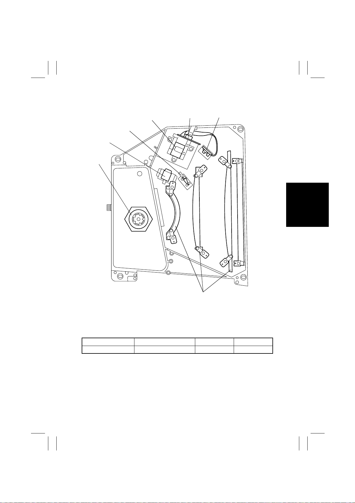
12-1. PH Components
4
3
2
1
5
6
7
1. Polygon Motor (M10)
2. Cylindrical Lens
3. SOS Mirror
4. Collimator Lens
Electrical Component Control Signal ON OFF
M10 PJ8A-3 L H
5. Laser Diode Board (PWB-B)
6. SOS Sensor
7. f-θ Lens
1167M023AC
M-23
Page 27
FrameMaker Ver.5.5E(PC) Di350 GENERAL, MECHANICAL/ELECTRICAL
98.12.18
1171SBM1202A
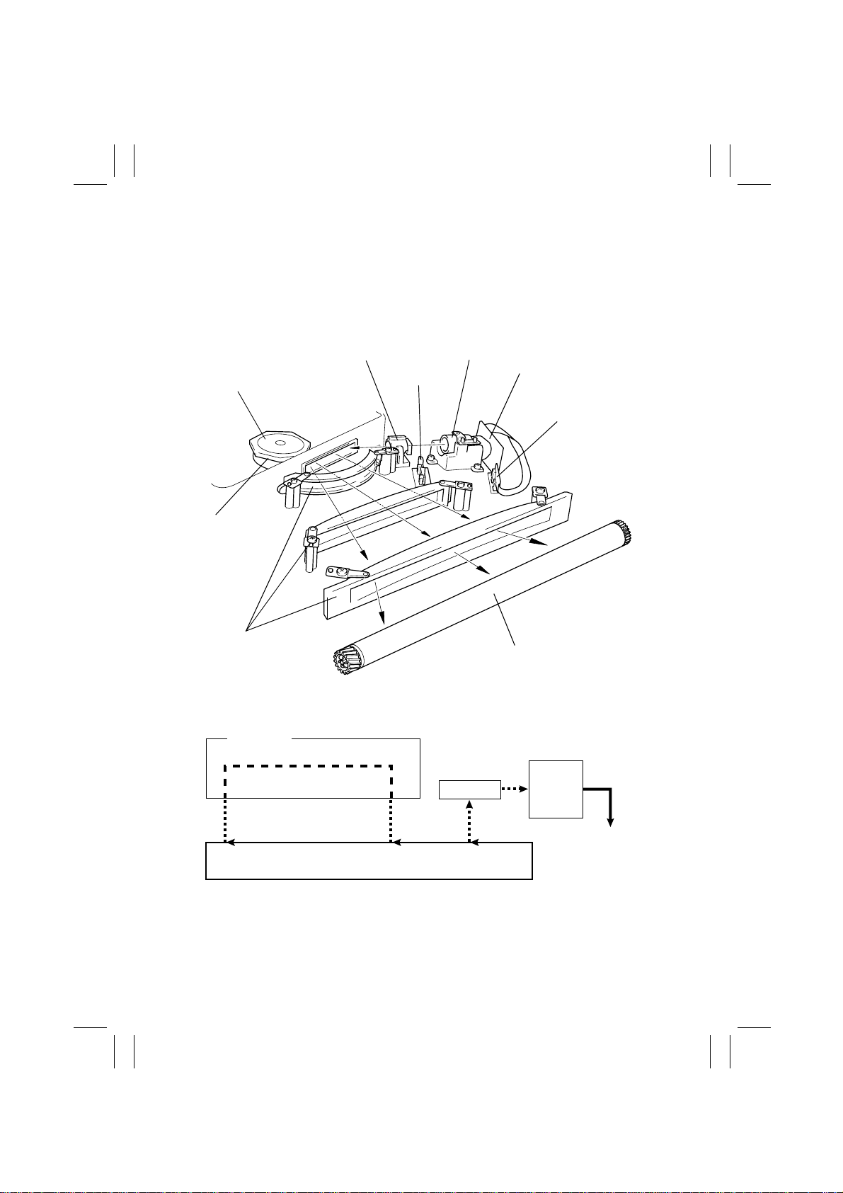
12-2. Laser Emission Timing (SOS Signal)
•
The signal output from the Master Board triggers the firing of the laser. The laser beam
travels to the Polygon Mirror, lens, and SOS Mirror to eventually hit the SOS Sensor,
which generates an SOS signal.
•
The SOS signal determines the laser emission timing for each line in the main scanning
direction.
Polygon Motor
(M10)
Polygon Mirror
f-θ Lens
PC Drum
Cylindrical Lens
SOS Mirror
Collimator Lens
Laser Diode Board
(PWB-B)
SOS Sensor
PC Drum
1167M024AD
SOS Mirror
A to B: LD activation
B to C: LD OFF
C to D: Laser beam exposure area according to the image data
M-24
SOS
Sensor
SOS Signal
ABCD
1171M038AA
Page 28
FrameMaker Ver.5.5E(PC) Di350 GENERAL, MECHANICAL/ELECTRICAL
98.12.18
1171SBM1300A
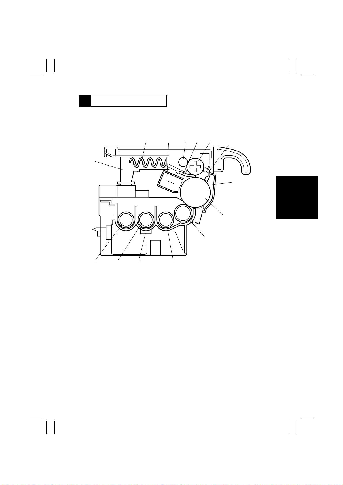
13 DEVELOPING UNIT
•
The Toner Conveying Rollers mix the toner and carrier particles together and carry the
toner/carrier mixture up to the Sleev e/Magnet Roller. The magnetic brush formed on the
surface of the roller allows the toner to come into contact with the charges on the surface
of the PC Drum, thus forming an electrostatic latent image.
12345
14
6
7
8
1. Spent Toner Recycling Coil
2. PC Drum Charge Corona
3. Spent Toner Feed Roller 2
4. Cleaning Blade
5. Spent Toner Feed Roller 1
6. PC Drum Paper Separator Finger
7. PC Drum Protective Shutter
9
1171M011AB
10111213
8. PC Drum
9. Sleeve/Magnet Roller
10. 1st Toner Conveying Roller
11. ATDC Sensor (E1)
12. 2nd Toner Conveying Roller
13. 3rd Toner Conveying Roller
14. Spent Toner Recycling Duct
M-25
Page 29

FrameMaker Ver.5.5E(PC) Di350 GENERAL, MECHANICAL/ELECTRICAL
98.12.18
1171SBM1301A
13-1. Sleeve/Magnet Roller
•
This copier employs the MT-HG system with a Sleeve/Magnet Roller having the following
magnetic characteristics.
•
Turning of the sleeve surrounding the Magnet Roller ensures that fresh developer from
the Developer Mixing Chamber is always being conveyed to the point of development
with respect to the PC Drum.
N1 : The point of development with the maximum magnetic flux density which
ensures that the carrier is firmly held onto the Sleeve Roller when toner is
attracted to the latent image.
S1, N2 : The magnetic flux density between these two poles is made low to ensure that
the developer remaining on the surface of the Sleeve Roller is smoothly recycled. They also prevent developer from scattering.
N3 : The developer brush is formed by this pole and its height is moderated before
the brush is regulated by the Doctor Blade.
S2a : This pole ensures that the developer is conveyed to the point of development
S2b : If developer is compacted and clogs at the Doctor Blade and, as a result, part
over the wide interval between N3 and N1.
of the surface of the Sleeve/Magnet Roller is not covered with developer, the
nearby developer around this pole with a weak magnetic force goes to those
uncovered areas. This helps prevent white lines from occurring on the copy.
S2a
S2b
N3
N1
N2
1171M027AA
PC Drum
S1
Sleeve/
Magnet Roller
1st Toner Conveying Roller
1167M076AB
M-26
Page 30
FrameMaker Ver.5.5E(PC) Di350 GENERAL, MECHANICAL/ELECTRICAL
98.12.18
1171SBM1302A
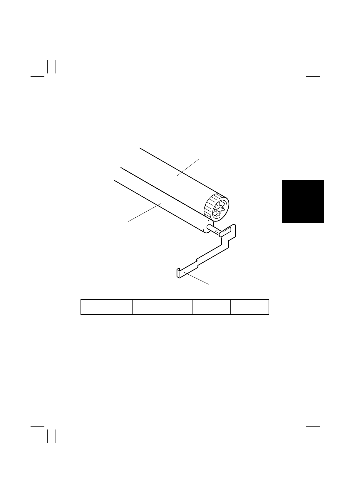
13-2. Developing Bias
•
The amount of toner attracted onto the surface of the PC Drum is controlled by varying
the developing bias voltage.
•
As the PC Drum deteriorates and its photoconductive layer begins to wear, it becomes
more sensitive to the increase in the amount of toner . As a countermeasure against this
problem, the developing bias v oltage is automatically s witched according to the PC Drum
temperature, thereby stabilizing the image quality level.
PC Drum
Sleeve/Magnet Roller
1171M012AB
Developing Bias Contact Terminal
Electrical Component Control Signal ON OFF
Vb PJ14A-1A L H
M-27
Page 31
FrameMaker Ver.5.5E(PC) Di350 GENERAL, MECHANICAL/ELECTRICAL
98.12.18
1171SBM1303A
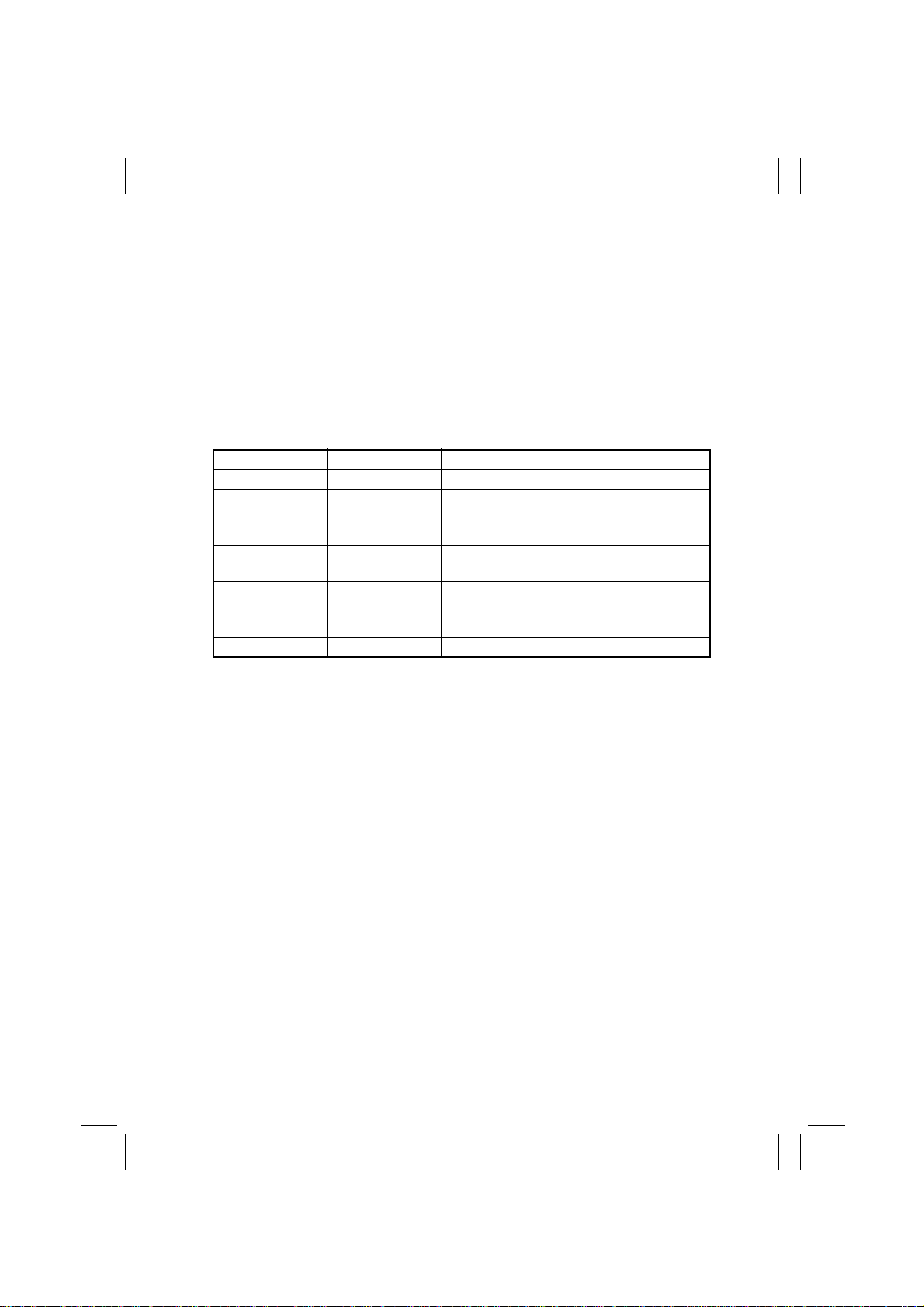
13-3. ATDC Sensor
•
The ATDC Sensor automatic adjustment is made when a new I/C is installed in the
copier. Toner replenishing control is thereafter controlled as detailed in the following.
1. ATDC Sensor Automatic Adjustment
•
The ATDC Sensor is automatically adjusted when a new I/C is loaded in the copier. During this sequence, the copier reads the sensor output value and sets it as the reference.
This reference value is stored in memory and used until the I/C reaches its service life.
2. Toner Replenishing Control
•
While the I/C Motor is turning, the A TDC Sensor samples T/C and, according to the readings, the copier provides the following controls.
T/C Ratio (%) Sampling Data (V) Control Details
More than 19 Less than 1.41 Defective ATDC Sensor
14 to 19 2.32 to 1.41 Toner replenished for 0 msec.
13 to 14 2.50 to 2.32
12 to 13 2.68 to 2.50
10 to 12 3.10 to 2.68
7 to 10 3.92 to 3.10 Passed onto the T/C recovery mode.
Less than 7 More than 3.92 Defective ATDC Sensor
✽
Toner replenishment represents the operation of the Sub Hopper Toner Replenishing
Motor.
Toner replenished for 54 msec. at intervals of
approx. 1 sec.
Toner replenished for 150 msec. at intervals of
approx. 1 sec.
Toner replenished for 378 msec. at intervals of
approx. 500 msec.
3. Toner Empty Control (T/C Recovery Mode)
•
When the control is passed onto the T/C recovery mode, the Sub Hopper Toner Replenishing Motor is energized to replenish the supply of toner into the Developing Unit and, if
T/C is recovered to a level of 14% or higher (2.32V or less) within 150 sec., it resets the
toner-empty condition.
M-28
Page 32
FrameMaker Ver.5.5E(PC) Di350 GENERAL, MECHANICAL/ELECTRICAL
98.12.18
1171SBM1304A
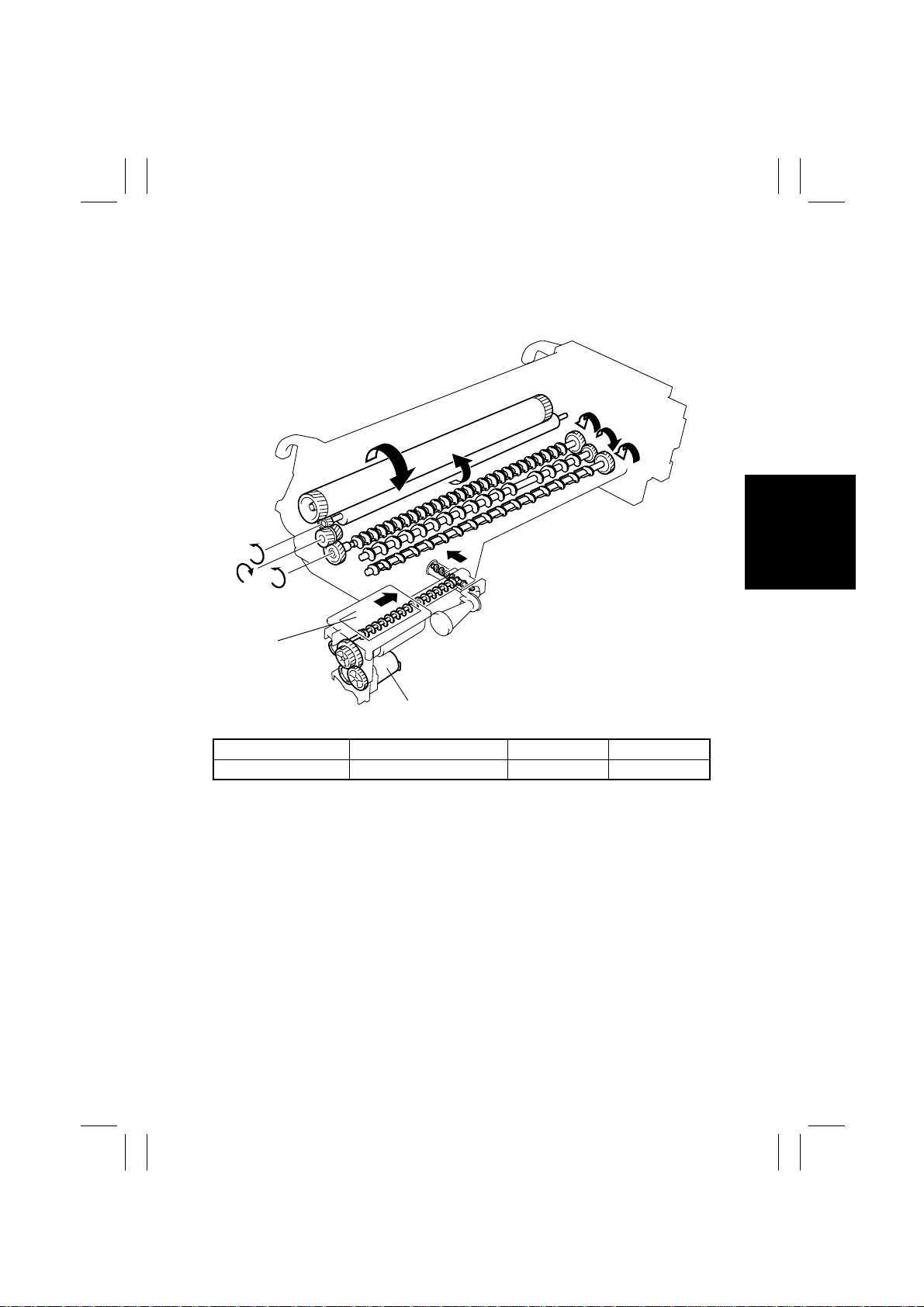
13-4. Sub Hopper Toner Replenishing Mechanism
•
Toner is replenished from the Sub Hopper to the Developing Unit by turning the Sub
Hopper Toner Replenishing Motor for the period of time controlled by the ATDC output
voltage (T/C).
Sub Hopper
1171M013AC
Sub Hopper Toner Replenishing Motor (M7)
Electrical Component Control Signal ON OFF
M7 PJ11A-8A DC24V L
M-29
Page 33
FrameMaker Ver.5.5E(PC) Di350 GENERAL, MECHANICAL/ELECTRICAL
98.12.18
1171SBM1305A
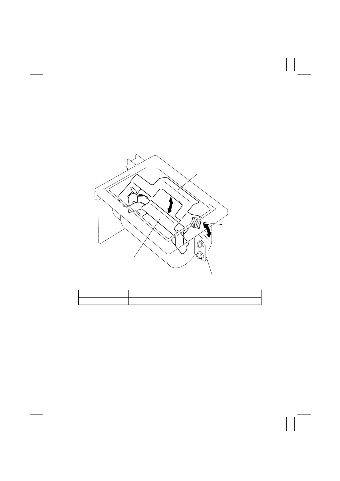
13-5. Sub Hopper Toner Empty Detecting Mechanism
•
A toner-empty condition in the Sub Hopper is detected by the Magnet Lever that moves
up and down as the Sub Hopper Toner Agitating Lever turns and actuates and deactuates the Sub Hopper Toner Empty Switch.
•
While the amount of toner in the Sub Hopper is more than the predetermined amount,
the Magnet Lever rests on the toner, keeping the Sub Hopper Toner Empty Switch deactuated even when the Sub Hopper Toner Agitating Lever turns. As toner is consumed,
the Magnet Lever lowers to eventually actuate the Sub Hopper Toner Empty Switch, at
which timing the copier detects a toner-empty condition in the Sub Hopper.
Magnet Lever
Magnet
Sub Hopper Toner Agitating Lever
1171M021AA
Sub Hopper Toner Empty Switch (S4)
Electrical Component Control Signal ON OFF
S4 PJ11A-7B L H
M-30
Page 34
FrameMaker Ver.5.5E(PC) Di350 GENERAL, MECHANICAL/ELECTRICAL
98.12.18
1171SBM1306A
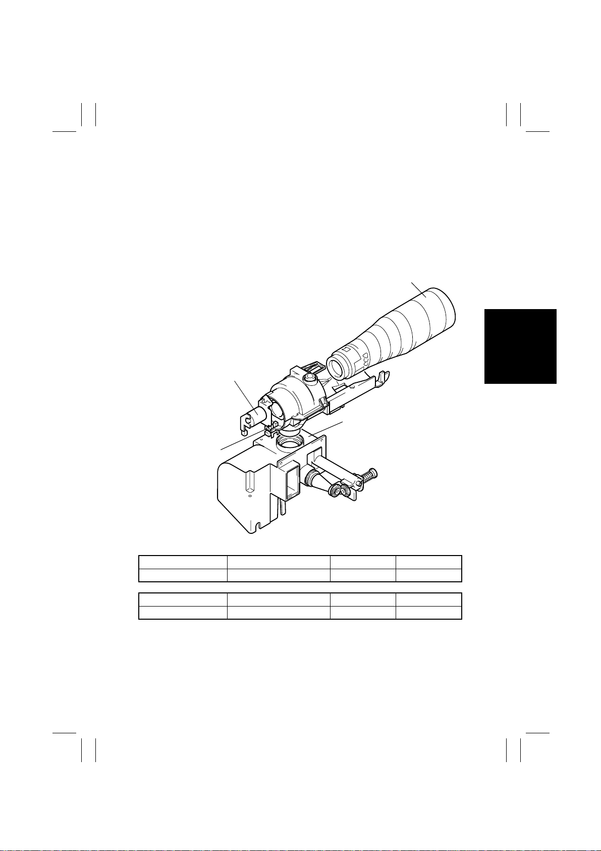
13-6. Main Hopper Toner Replenishing Mechanism
•
When a toner-empty condition in the Sub Hopper is detected, the Main Hopper Toner
Replenishing Motor is energized to turn the Toner Bottle, thereby supplying toner from
the Main Hopper to the Sub Hopper.
•
The Toner Bottle Home Position Sensor mounted on the coupling ensures that the Toner
Supply Port in the Toner Bottle is positioned at the top whenever the bottle is stopped.
•
The Toner Bottle Cover Sensor detects whether the Toner Bottle Cover is open. If the
cover is open, the copier does not authorize the initiation of a new copy cycle. If the
cover is opened during a copy cycle, the copier interrupts the cycle.
Toner Bottle
Main Hopper Toner
Replenishing Motor (M6)
Sub Hopper
Toner Bottle Home
Position Sensor (PC10)
1171M020AB
Electrical Component Control Signal ON OFF
M6 PJ11A-4A DC24V L
Electrical Component Control Signal Unblocked Blocked
PC10 PJ11A-2B L H
M-31
Page 35
FrameMaker Ver.5.5E(PC) Di350 GENERAL, MECHANICAL/ELECTRICAL
98.12.18
1171SBM1307A
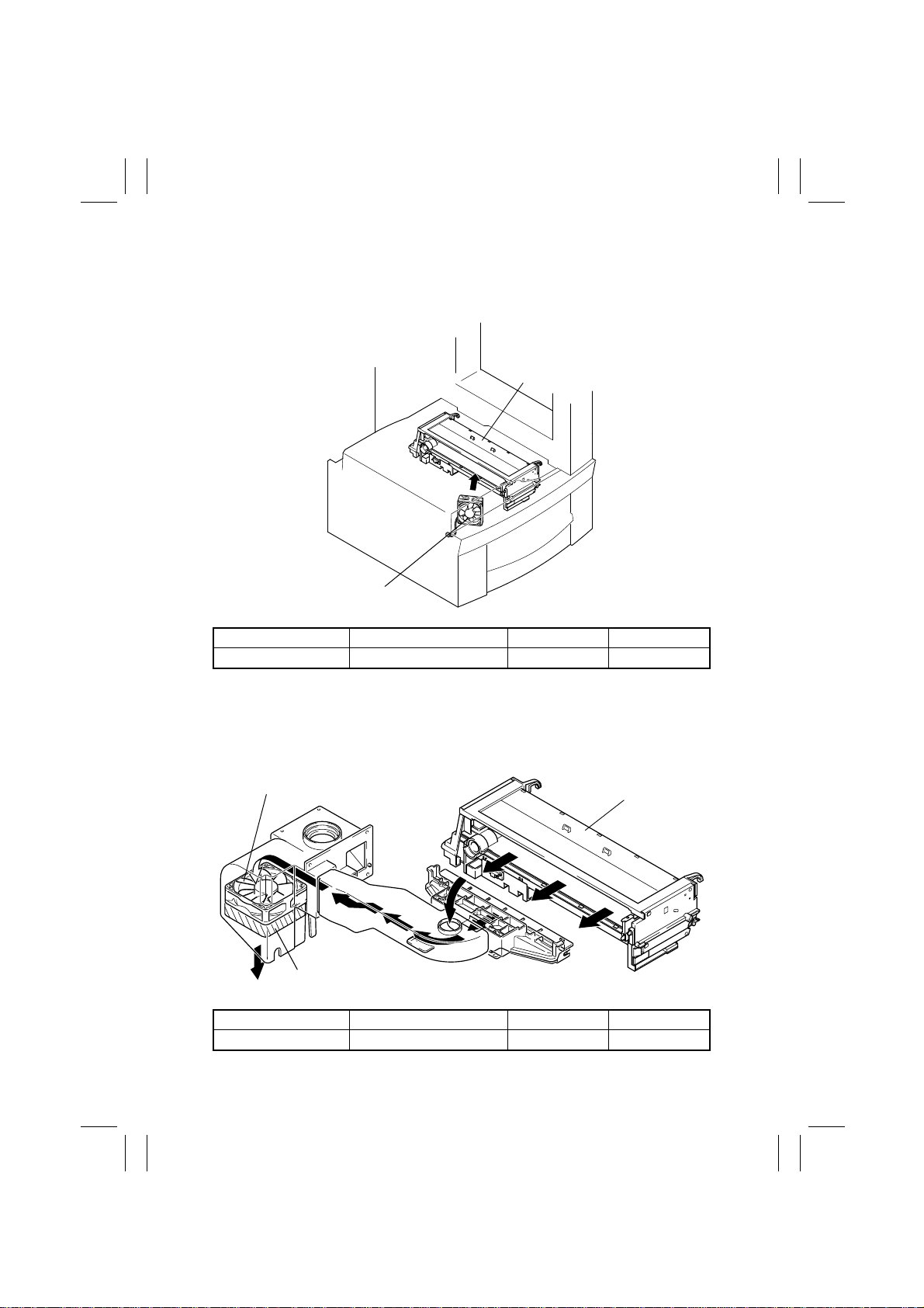
13-7. I/C Cooling Fan Motor
•
The I/C Cooling Fan Motor prevents the temperature inside the copier (around the entire
I/C) from rising inordinately.
I/C
I/C Cooling Fan
Motor (M9)
1171M032AB
Electrical Component Control Signal ON OFF
M9 PJ18A-10 DC24V L
1171SBM1308A
13-8. Ozone Fan Motor
•
Ozone produced by the PC Drum Charge Corona is absorbed by the Ozone Filter from
the air being drawn out of the copier by the Ozone Fan Motor.
Ozone Fan Motor (M8)
Ozone Filter
Electrical Component Control Signal ON OFF
M8 PJ11A-1A DC24V L
I/C
1171M023AC
M-32
Page 36
FrameMaker Ver.5.5E(PC) Di350 GENERAL, MECHANICAL/ELECTRICAL
98.12.18
1171SBM1400A
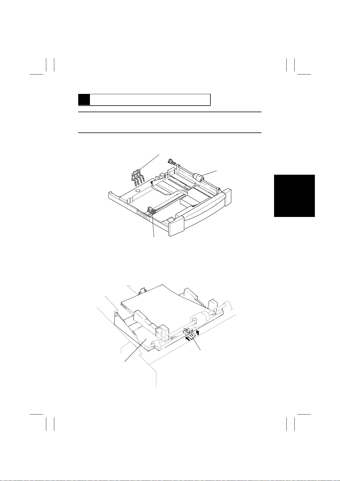
14 PAPER TAKE-UP/FEED SECTION
NOTE
•
For the details of the 2nd Cassette (500-Sheet Cassette), see the rele v ant option service
manual.
•
This copier employs the Multi-Purpose (MP) Cassette whose capacity is about 250
sheets (about 20 sheets for special paper).
Paper Size Detecting Board (PWB-I)
Paper Take-Up Roll
Trailing Edge Stop
1171SBM1401A
1167M055AA
14-1. MP Cassette Paper Lifting Plate
•
The Paper Lifting Plate installed in the MP Cassette is spring-loaded to push the paper
stack upward. When the cassette is slid into the copier, the lever located on the bottom
of the cassette and used to lock down the Paper Lifting Plate is pushed and unlocked,
allowing the Paper Lifting Plate to push the paper stack upward.
Lever
Paper Lifting Plate
1167M080AA
M-33
Page 37
FrameMaker Ver.5.5E(PC) Di350 GENERAL, MECHANICAL/ELECTRICAL
98.12.18
1171SBM1402A
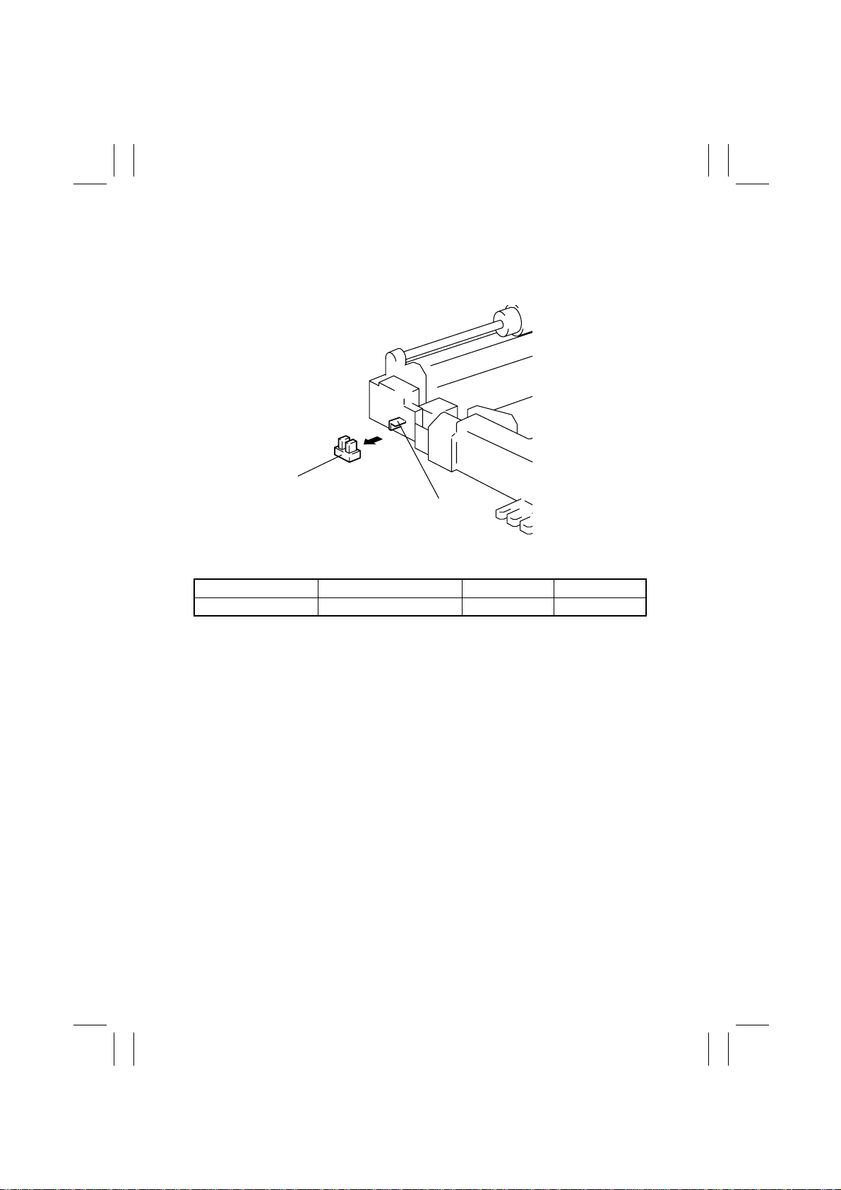
14-2. MP Cassette-in-Position Detection
•
When the MP Cassette is slid into the copier, the light blocking plate located in the rear of
the cassette blocks the Cassette Set Sensor and the copier determines that the MP Cassette has been slid into position.
Cassette Set Sensor (PC6)
Light Blocking Plate
1167M052AB
Electrical Component Control Signal Unblocked Blocked
PC6 PJ13A-5B H L
M-34
Page 38
FrameMaker Ver.5.5E(PC) Di350 GENERAL, MECHANICAL/ELECTRICAL
98.12.18
1171SBM1403A
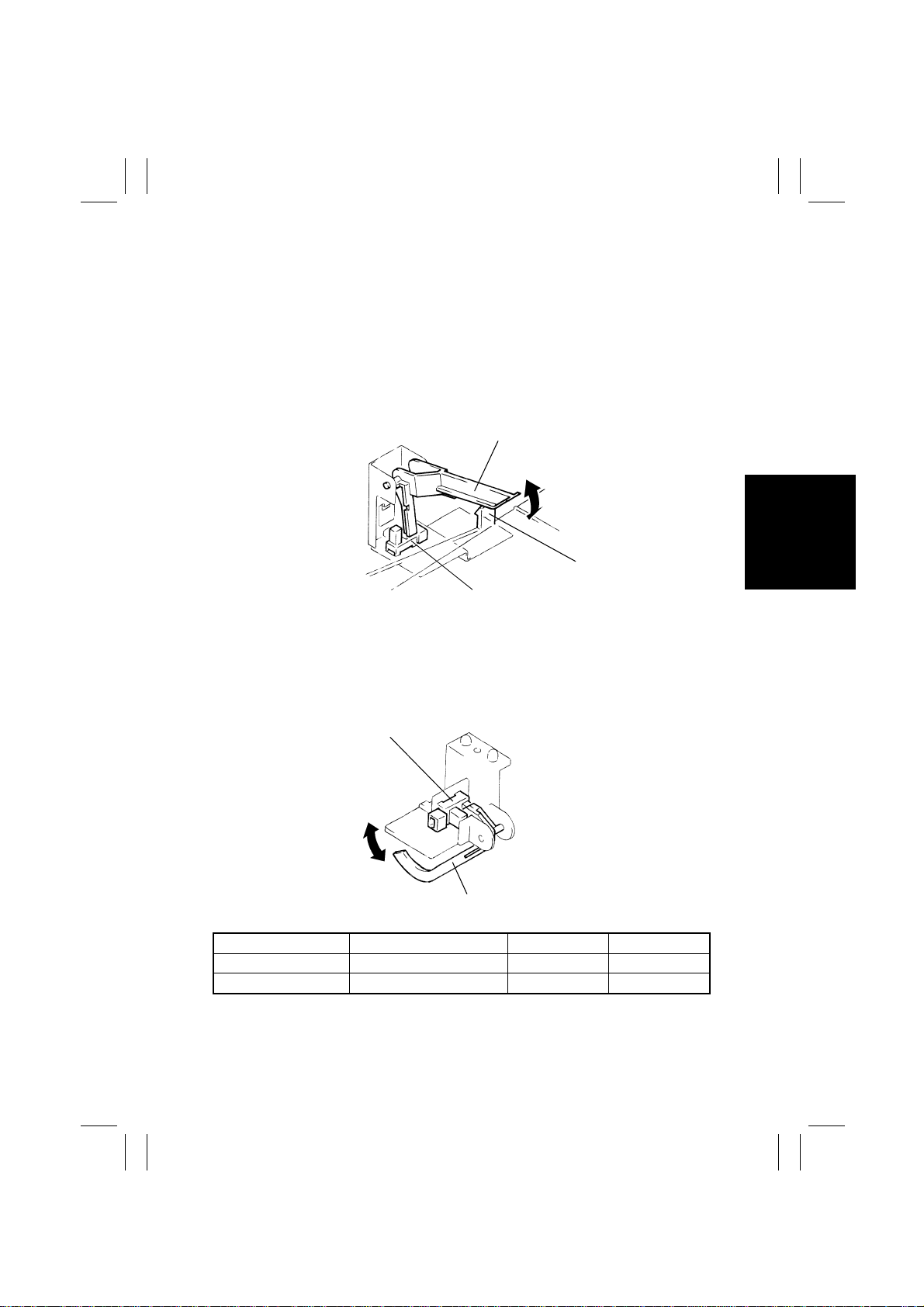
14-3. MP Cassette Paper Empty Detection
•
Two sensors are used in this copier: the Paper Empty Sensor detects a paper-empty
condition, while the Paper Near-Empty Sensor detects a paper near-empty condition.
Paper Near-Empty Detection:
•
A paper near-empty condition is detected as the paper is consumed and when the NearEmpty Lever lowers to eventually block the sensor (L).
•
At this time, the MP Cassette Paper Empty LED starts blinking.
•
A paper-empty condition results when about 50 more sheets of paper are used after the
near-empty condition has been detected.
Near-Empty Lever
Paper Lifting Lever
Paper Near-Empty
Sensor (PC4)
1167M071AC
Paper Empty Detection:
•
A paper-empty condition is detected as the paper is consumed and when the Empty
Lever lowers to eventually block the sensor (L).
•
At this time, the MP Cassette Paper Empty LED lights up steadily.
Paper Empty Sensor
(PC5)
Empty Lever
1167M073AD
Electrical Component Control Signal Unblocked Blocked
PC4 PJ14A-13A H L
PC5 PJ13A-2B H L
M-35
Page 39
FrameMaker Ver.5.5E(PC) Di350 GENERAL, MECHANICAL/ELECTRICAL
98.12.18
1171SBM1404A
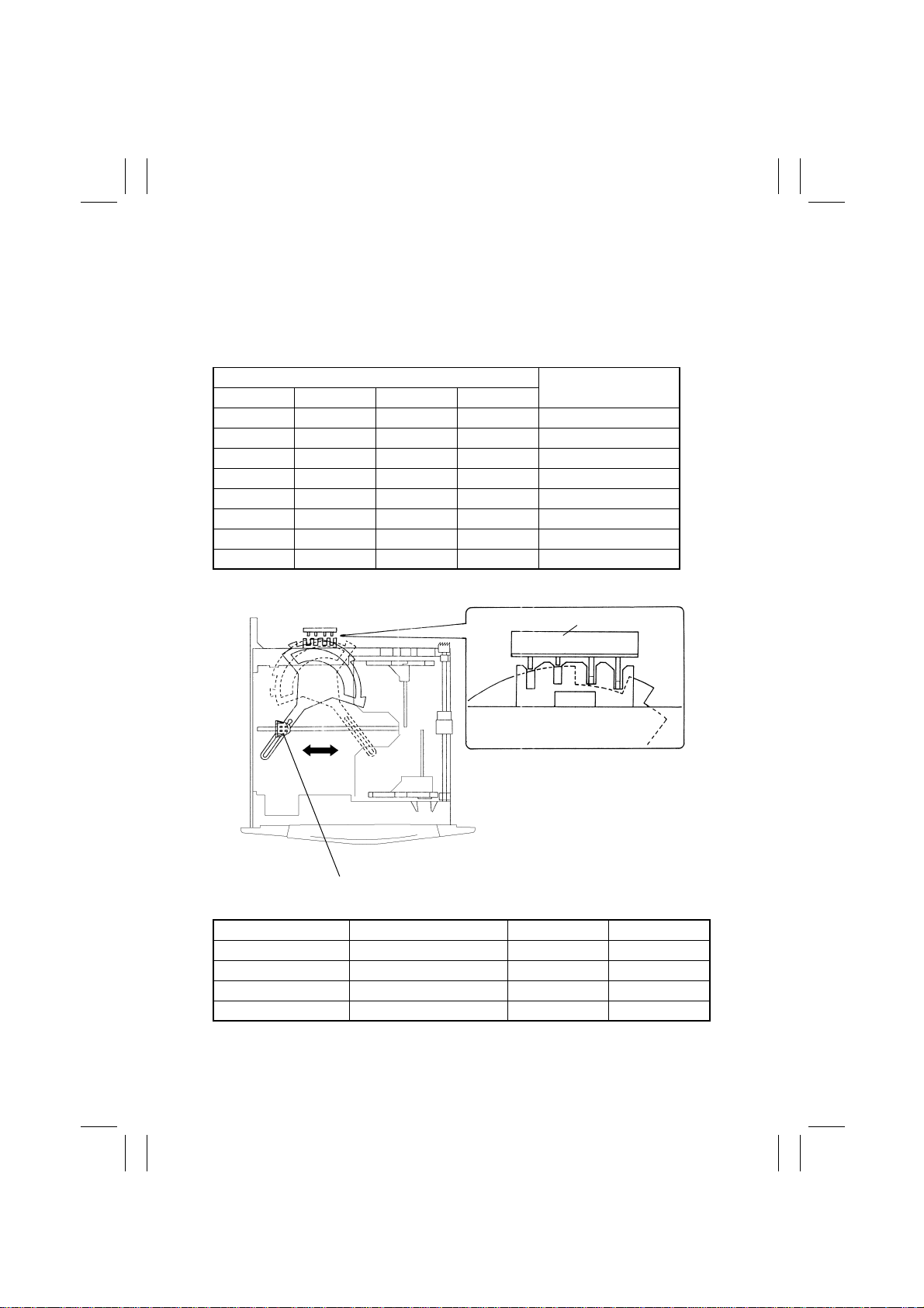
14-4. MP Cassette Paper Size Detection
•
The Paper Size Detecting Board detects the length of the paper (FD).
•
A lever is connected to the Trailing Edge Stop of the cassette and, as the stop is slid to
the size of the paper loaded in the cassette, the lever is moved to turn ON and OFF the
size detecting switches mounted on the copier side.
•
The control panel settings are necessary for any paper size other than the following.
Paper Size Detecting Switches (PWB-I)
1234
ON OFF OFF OFF A3L, 11”×17”L
OFF OFF OFF OFF B4L, 8-1/2”×14”L
OFF ON ON ON A4L
ON ON ON ON B5L, 8-1/2”×11”L
ON ON OFF OFF A4C/A5L
ON OFF OFF ON B5C
OFF ON OFF OFF A5C
ON ON ON OFF 8-1/2”×11”C
Paper Size Detecting Board (PWB-I)
12 34
Paper Size
Trailing Edge Stop
Electrical Component Control Signal ON OFF
PWB-I (1) PJ14A-1B L H
PWB-I (2) PJ14A-2B L H
PWB-I (3) PJ14A-3B L H
PWB-I (4) PJ14A-4B L H
1167M060AC
M-36
Page 40
FrameMaker Ver.5.5E(PC) Di350 GENERAL, MECHANICAL/ELECTRICAL
98.12.18
1171SBM1405A
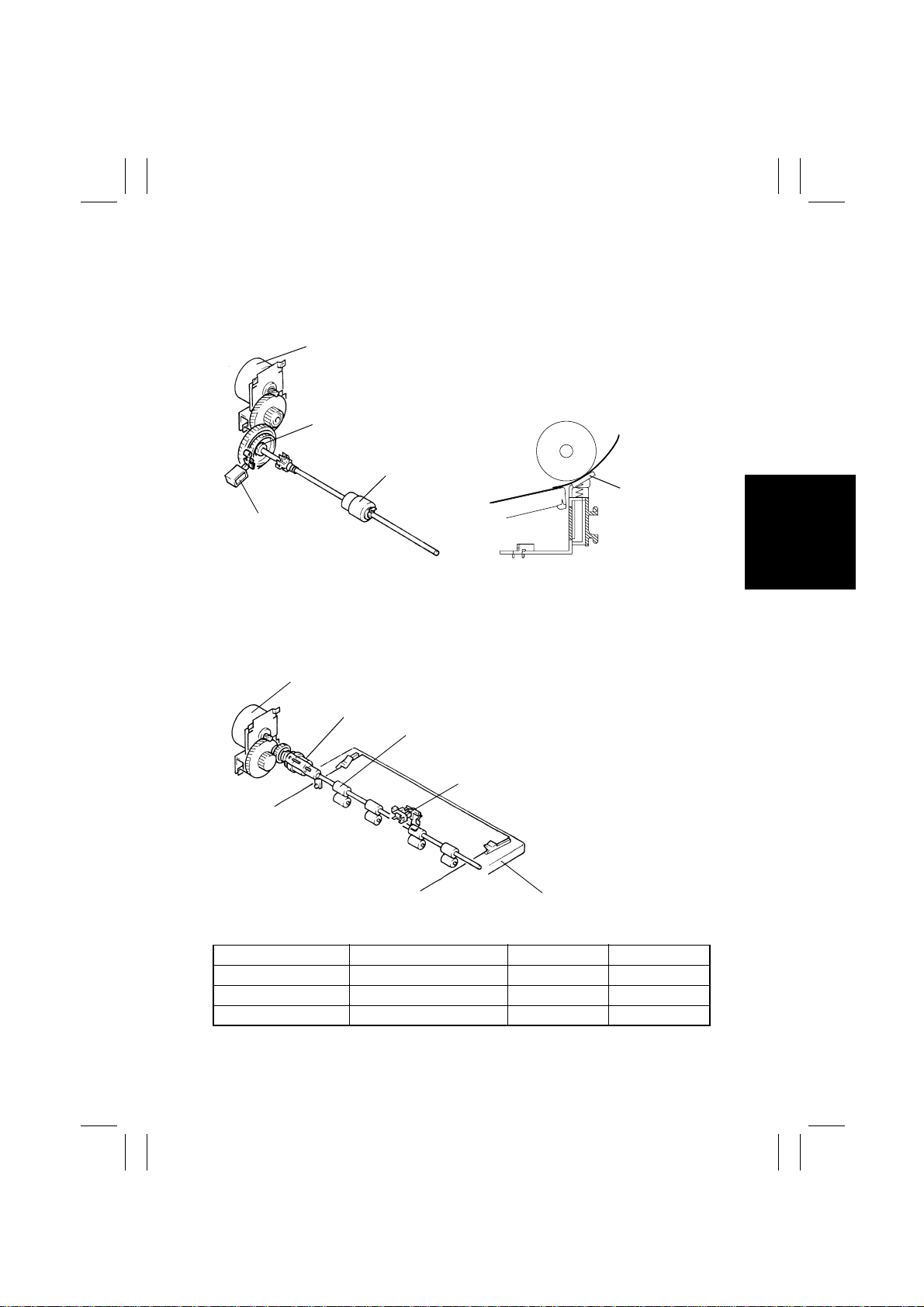
14-5. Paper Take-Up Mechanism
•
Drive from the Main Motor is transmitted to the Paper Take-Up Clutch (spring clutch) and,
by energizing the Paper Take-Up Solenoid, the Paper Take-Up Roll is turned.
•
The paper separating mechanism employs a Paper Separator Pad.
Main Motor (M2)
Paper Take-Up Clutch
Paper Take-Up Roll
Paper Separator
Paper Take-Up Sole-
Pad
noid (SL1)
1167M054AB1167M038AB
1171SBM1406A
14-6. Manual Bypass Tray
1. Construction of the Manual Bypass Tray
•
Drive from the Main Motor is transmitted to the Manual Paper Feed Take-Up Clutch and,
by energizing this clutch, the Manual Feed Paper Take-Up Roll is turned.
Main Motor (M2)
Manual Paper Feed Take-Up Clutch (CL3)
Manual Feed Paper Take-Up Roll
Manual Feed Paper Take-Up Sensor (PC8)
Manual Bypass Tray
1167M067AC
Electrical Component Control Signal ON OFF
M2 PJ16A-1 L H
SL1 PJ13A-13B L H
CL3 PJ4A-9A L H
M-37
Page 41
FrameMaker Ver.5.5E(PC) Di350 GENERAL, MECHANICAL/ELECTRICAL
98.12.18
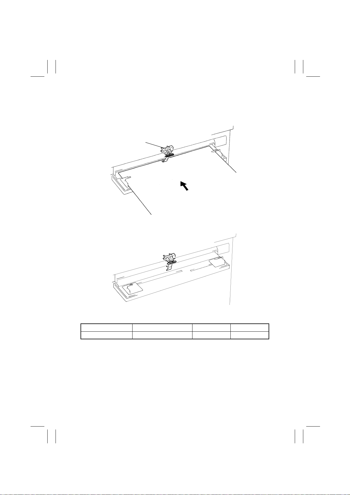
2. Manual Feed Paper Take-Up Detection
•
The Manual Feed P aper Take-Up Sensor detects a sheet of paper that is fed via the Manual Bypass Tray.
•
The size and type of the paper for manual feed are set on the control panel.
<Paper Present: Unblocked (H)>
Manual Feed Paper Take-Up Sensor (PC8)
1167M086AA
<Paper Not Present: Blocked (L)>
1167M085AA
Electrical Component Control Signal Unblocked Blocked
PC8 PJ4A-7B H L
1171SBM1407A
14-7. Paper Take-Up Retry Mechanism
•
To minimize the occurrence of a paper misfeed due to a slippery Paper Take-Up Roll, the
Paper Take-Up Solenoid is energized a second time if a sheet of paper fails to reach the
Synchronizing Roller Sensor within a given period of time after the solenoid has been
energized first.
•
A paper take-up misfeed results if the sheet of paper does not reach the Synchronizing
Roller Sensor even after two paper take-up sequences.
M-38
Page 42
FrameMaker Ver.5.5E(PC) Di350 GENERAL, MECHANICAL/ELECTRICAL
98.12.18
1171SBM1500A
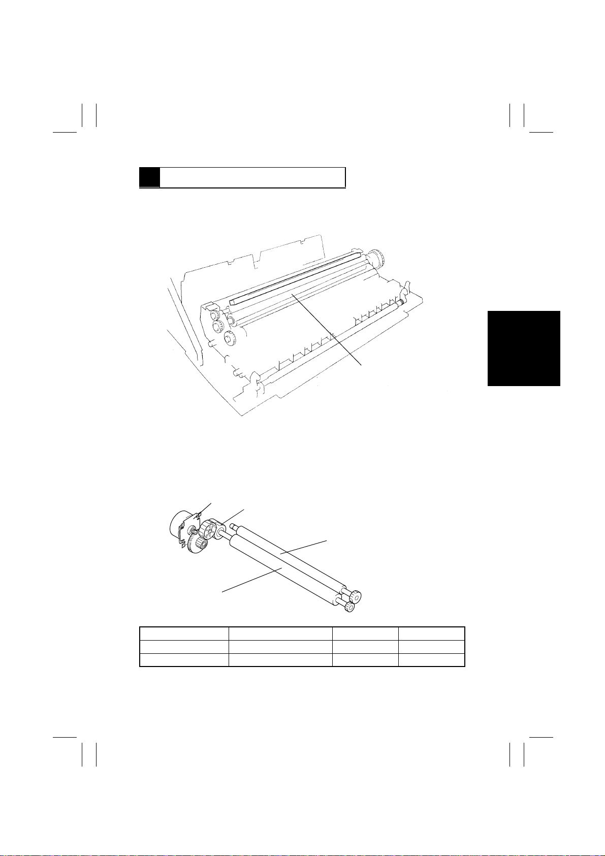
15 SYNCHRONIZING ROLLERS
•
The Synchronizing Rollers of this copier are located inside the Right Door. They are easily accessible for misfeed clearing by just opening the Right Door.
Synchronizing Roller
1171M029AA
1171SBM1501A
15-1. Synchronizing Roller Drive Mechanism/Control
•
The Synchronizing Rollers are turned by the drive from the Main Motor transmitted to the
Synchronizing Clutch.
•
The rollers are started when the Synchronizing Clutch is deenergized.
Main Motor (M2)
Right Synchronizing Roller
Electrical Component Control Signal ON OFF
M2 PJ16A-1 L H
CL1 PJ13A-2A L H
Synchronizing Clutch (CL1)
Left Synchronizing Roller
1167M064AA
M-39
Page 43
FrameMaker Ver.5.5E(PC) Di350 GENERAL, MECHANICAL/ELECTRICAL
98.12.18
1171SBM1502A
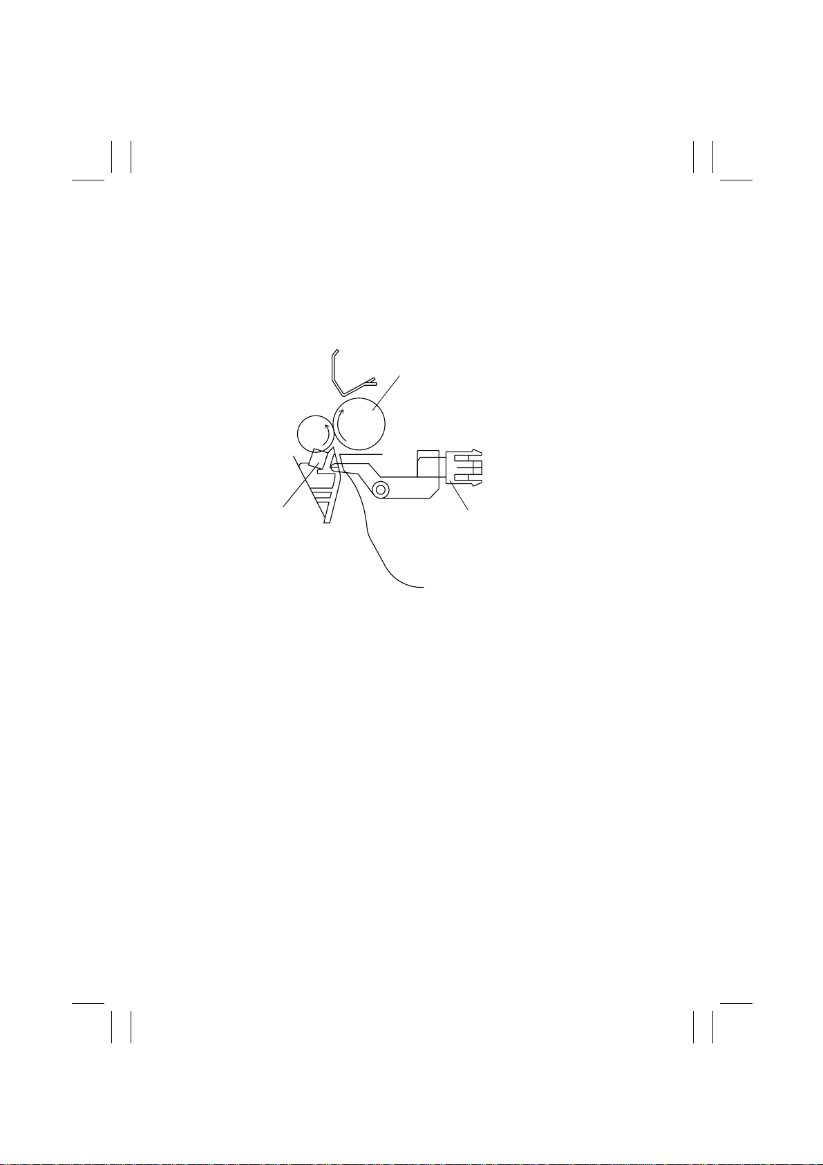
15-2. Paper Dust Remover
•
The Paper Dust Remov er is installed so that it makes contact with the Left Synchronizing
Roller. It is intended for preventing paper dust from sticking to the surface of the PC
Drum.
•
As the roller turns in contact with the Paper Dust Remover, triboelectric charging occurs,
which attracts paper dust from the paper that passes between the two rollers and the
dust is, in turn, transferred onto the Paper Dust Remover.
Synchronizing Roller
Paper Dust Remover
Synchronizing Roller Sensor (PC2)
1171M026AB
M-40
Page 44
FrameMaker Ver.5.5E(PC) Di350 GENERAL, MECHANICAL/ELECTRICAL
98.12.18
1171SBM1600A
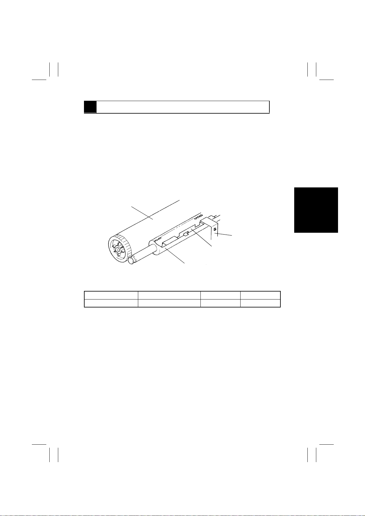
16 IMAGE TRANSFER AND PAPER SEPARATION
Image Transfer
•
This copier employs an Image Transfer Roller to transfer the image to the paper. The
High Voltage Unit applies an image transfer current to this roller. To ensure that image
transfer efficiency is stabilized, the image transfer current is automatically v aried according to the paper size, paper type, and the B/W ratio of the original.
•
To prevent toner from sticking to the Image Transfer Roller, an image transfer voltage of
-975V is applied to the roller for cleaning.
Paper Separation
•
To neutralize any charge left on the paper, to which the image has been transferred, the
High Voltage Unit applies a voltage of -1200V via a ground plate to the Charge Neutralizing Plate.
PC Drum
Ground Plate
Charge Neutralizing Plate
Image Transfer Roller
1167M082AA
Electrical Component Control Signal ON OFF
Image transfer output PJ14A-2A L H
M-41
Page 45
FrameMaker Ver.5.5E(PC) Di350 GENERAL, MECHANICAL/ELECTRICAL
98.12.18
1171SBM1700A
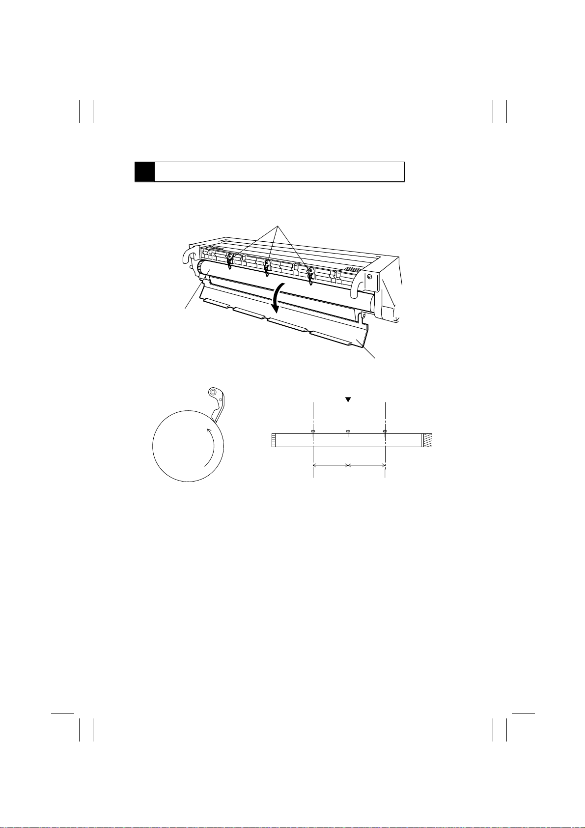
17 PC DRUM PAPER SEPARATOR FINGERS
•
The three PC Drum Paper Separator Fingers fitted to the I/C mechanically separate
paper from the surface of the PC Drum to ensure good and positive paper separation.
PC Drum Paper Separator Fingers
PC Drum
1171M014AA
PC Drum Protective Shutter
Paper Path Center
8.5cm
8.5cm
1167M053AC
M-42
Page 46
FrameMaker Ver.5.5E(PC) Di350 GENERAL, MECHANICAL/ELECTRICAL
98.12.18
1171SBM1800A
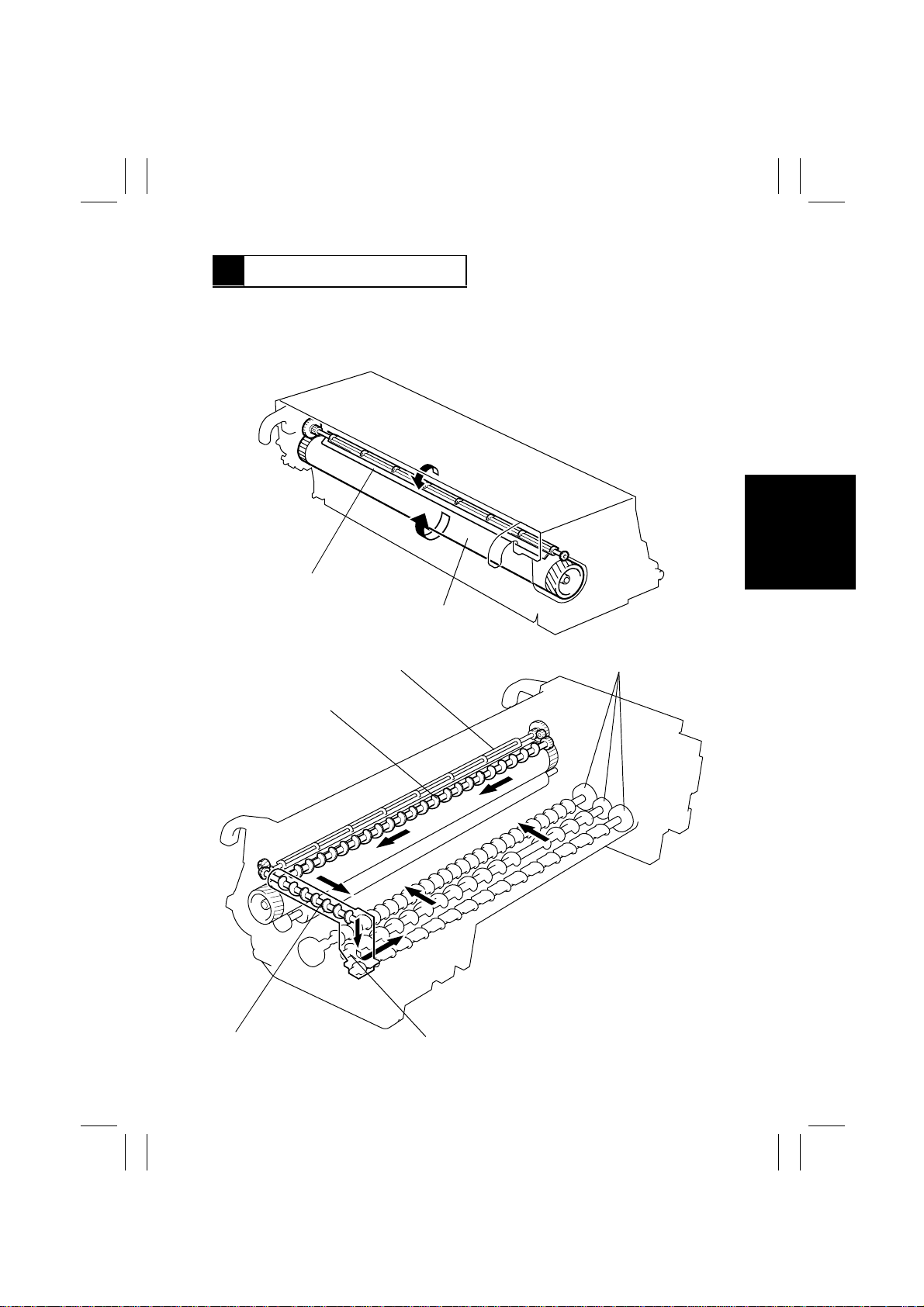
18 PC DRUM CLEANING
•
This copier employs a spent toner recycling mechanism. The Cleaning Blade which is
held pressed against the surface of the PC Drum scrapes residual toner off the surface.
The waste toner is conveyed by Spent Toner Feed Roller 1 and 2 to the Spent Toner
Recycling Duct and eventually back to the Developer Mixing Chamber.
Cleaning Blade
Spent Toner Feed Roller 1
Spent Toner Feed Roller 2
Spent Toner Recy cling Coil
PC Drum
Recycling Duct
1171M015AA
Toner Conveying Rollers
1171M016AA
M-43
Page 47
FrameMaker Ver.5.5E(PC) Di350 GENERAL, MECHANICAL/ELECTRICAL
98.12.18
1171SBM1900A
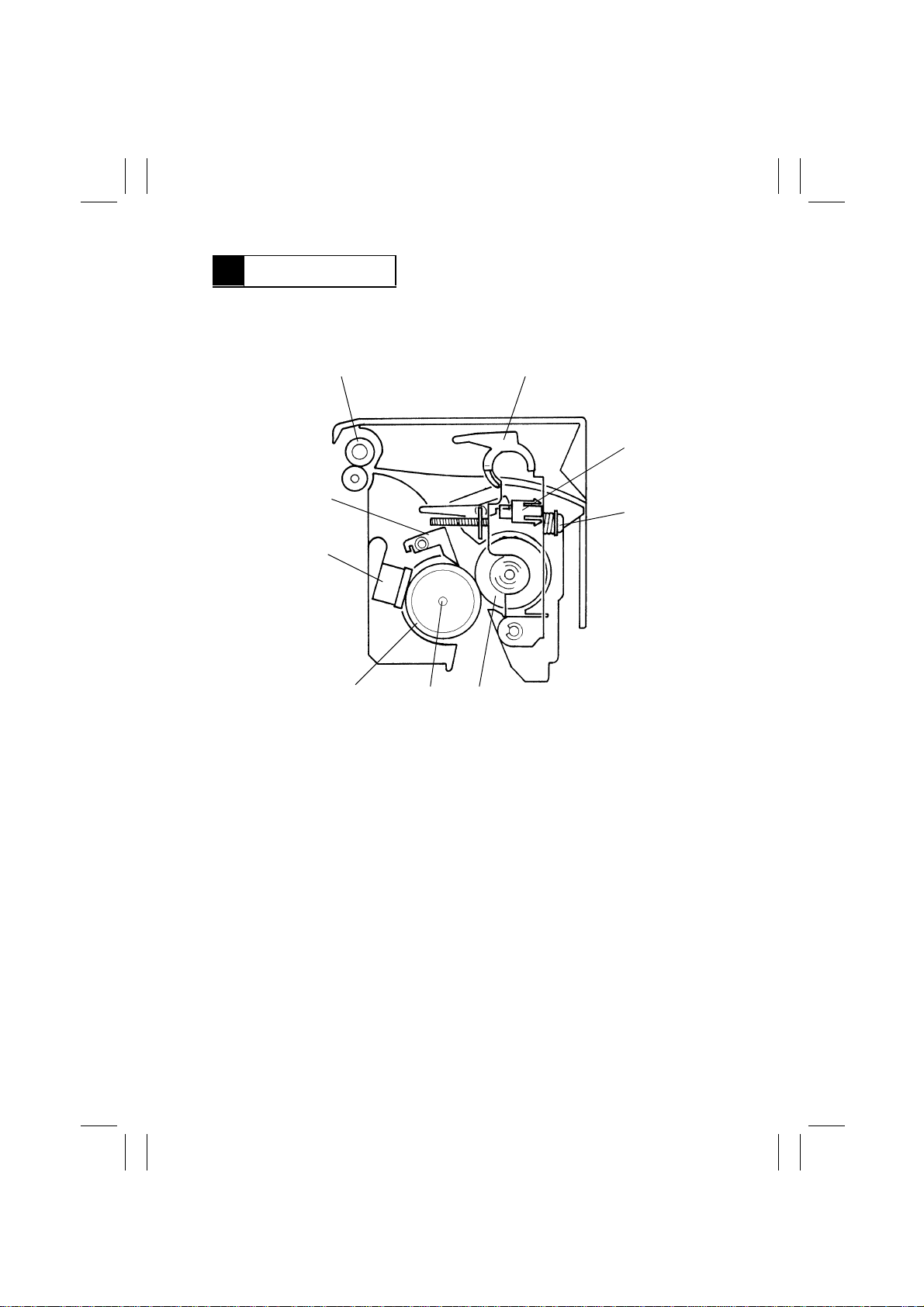
19 FUSING UNIT
•
The paper, to which the de v eloped image is y et to be fix ed, i s f ed through heated Left and
Right Fusing Rollers. The heat and pressure applied at this time fixes the image permanently to the paper.
12
3
9
8
7
1. Paper Exit Roller
2. Fusing Misfeed Clearing Lever
3. Paper Exit Sensor (PC3)
4. Pressure Spring
5. Right Fusing Roller
6
5
6. Fusing Roller Heater Lamp (H1)
7. Left Fusing Roller
8. Fusing Roller Thermostat (TS1)
9. Fusing Paper Separator Finger
4
1167M078AB
M-44
Page 48
FrameMaker Ver.5.5E(PC) Di350 GENERAL, MECHANICAL/ELECTRICAL
98.12.18
1171SBM1901A
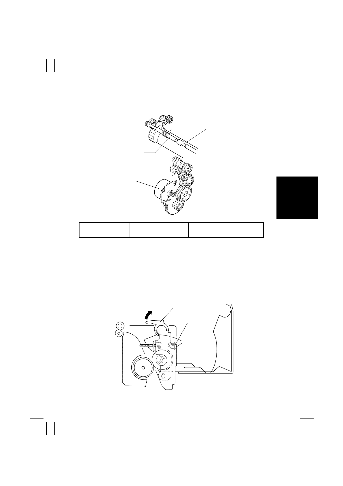
19-1. Drive Mechanism
•
Drive from the Main Motor is transmitted via a gear train to the Right Fusing Roller.
Right Fusing Roller
Paper Exit Roller
Main Motor (M2)
1167M057AB
Electrical Component Control Signal ON OFF
M2 PJ16A-1 L H
1171SBM1902A
19-2. Fusing Rollers Pressure Mechanism
•
To ensure that there is a certain width of area of contact between the Left and Right Fusing Rollers, pressure springs are installed.
•
The rollers are held pressed against each other at all times and they are released only
when servicing the copier or replacing parts.
•
The pressure between the two rollers is approx. 17 kg.
•
The rollers can be released by moving the Fusing Misfeed Clearing Lever in the direction
of the arrow.
Fusing Misfeed Clearing Lever
Pressure Spring
1167M077AF
M-45
Page 49
FrameMaker Ver.5.5E(PC) Di350 GENERAL, MECHANICAL/ELECTRICAL
98.12.18
1171SBM1903A
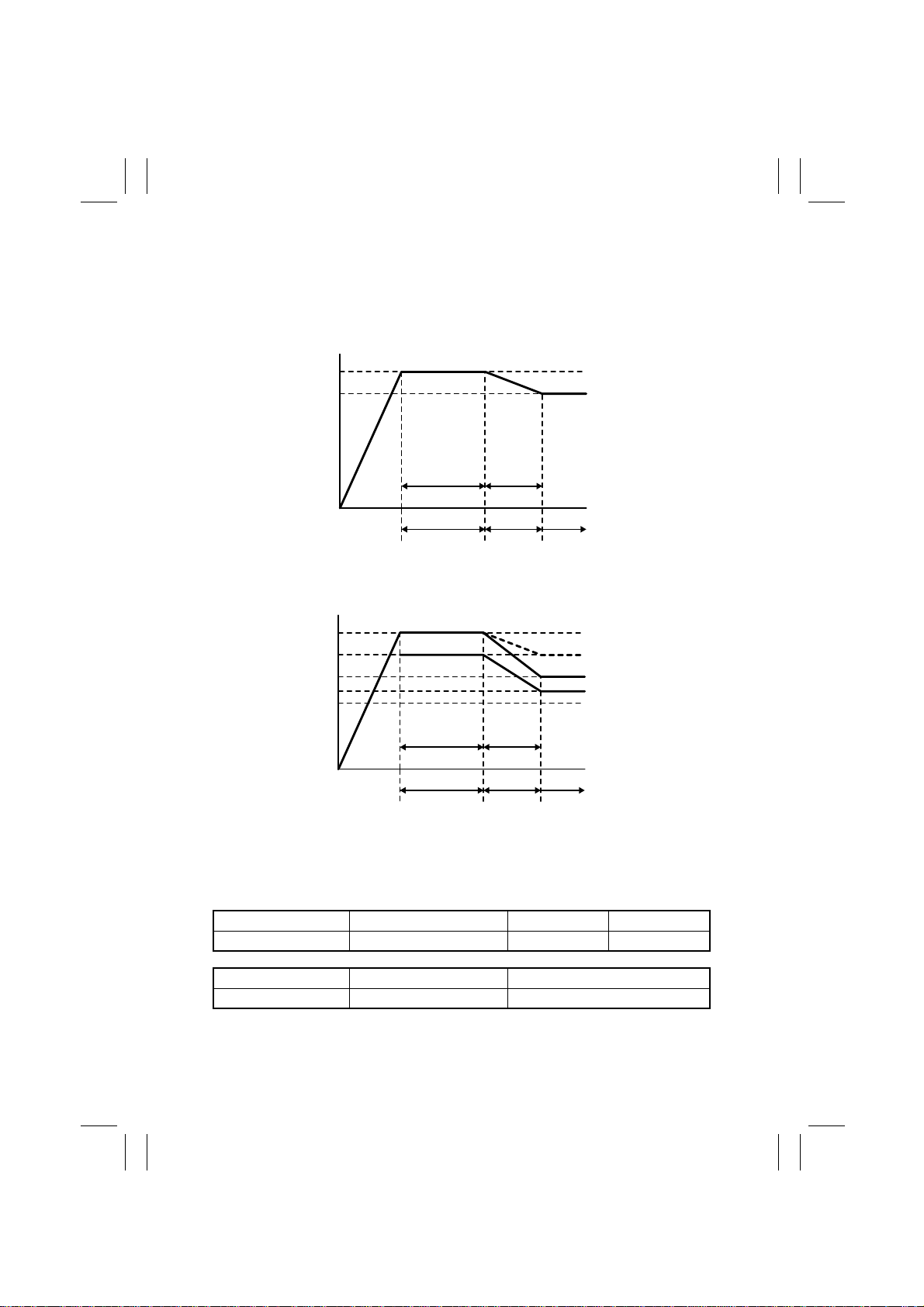
19-3. Fusing Temperature Control
•
The Fusing Roller Heater Lamp inside the Left Fusing Roller provides the following temperature control.
- Temperature Control During Standby State -
200
185
Approx.
1 min.
Warm-Up
Approx.
5 min.
Mode 1 Mode 2 Mode 3
Completed
(200°C)
1171M031AB
- Temperature Control During a Copy Cycle -
210
200
190
180
175
Approx.
5 min.
Approx.
1 min.
Special paper
Plain paper (1-sided)
Plain paper (2-sided)
Transparencies
Mode 1 Mode 2 Mode 3
1171M030AB
<Temperature Control>
•
The Fusing Roller Thermistor detects the surface temperature of the Left Fusing Roller.
It provides an analog voltage input to the Master Board allowing the copier to control the
fusing temperature.
Electrical Component Control Signal ON OFF
H1 PJ16A-8 L H
Electrical Component Control Signal Low Temp. ↔ High Temp.
TH1 PJ16A-5 Analog input
M-46
Page 50
FrameMaker Ver.5.5E(PC) Di350 GENERAL, MECHANICAL/ELECTRICAL
98.12.18
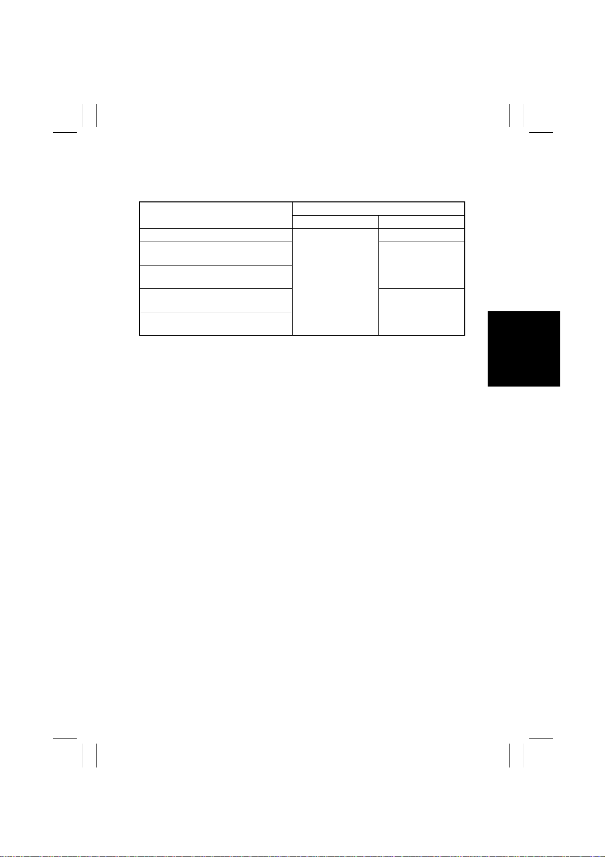
<Temperature Control by Mode>
•
The mode that is initiated following the completion of a warm-up cycle varies as detailed
below depending on the machine condition and the Fusing Roller temperature at the
restart of temperature control.
Machine Condition
Power is turned ON.
Temperature control is interrupted during
warm-up.
Temperature control is interrupted during
mode 1.
Temperature control is interrupted during
mode 2.
Temperature control is interrupted during
mode 3.
1171SBM1904A
Fusing Roller Temperature
Less than 100°C 100°C or higher
Mode 2
Mode 1
Mode 1
Mode 2
19-4. CPM Control
•
As a measure to prevent the temper ature on the edges of the Fusing Rollers (over which
no part of paper passes) from rising in a multi-copy cycle using small size paper (width of
250 mm or less), the paper feed interval is made greater.
<Control>
•
If a sheet of small size paper is taken up and f ed in during mode 1, control is switched to
mode 2.
•
The number of sheets of small size paper that are fed through is counted.
<Timing>
•
The counter reaches 30.
•
The plain/special paper counter reaches N specified below:
If the control is in mode 1 or mode 2 when the counter starts counting, N = 30.
If the control is in mode 3 when the counter starts counting, N = 100.
<Resetting>
•
If a period of 2 min. or more elapses, during which the counter does not count up after
the counter has started counting, the counter is cleared resetting the CPM control.
M-47
Page 51
FrameMaker Ver.5.5E(PC) Di350 GENERAL, MECHANICAL/ELECTRICAL
98.12.18
1171SBM2000A
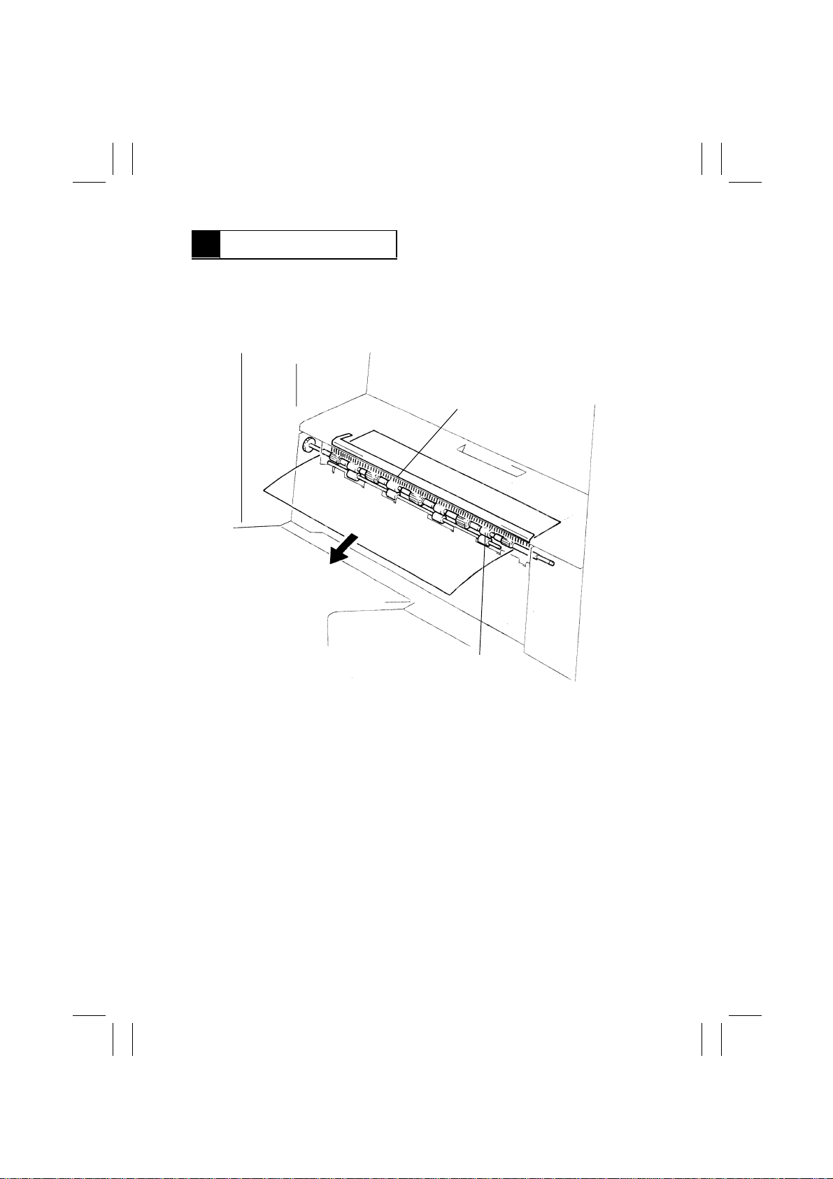
20 PAPER EXIT UNIT
•
The Paper Exit Roller feeds the paper , to which the de v el oped image has been fixed, out
of the copier. The Charge Neutralizing Brush touches the surface of the sheet of paper
being fed out of the Fusing Unit to neutralize any static charge left on it. This effectively
prevents two sheets of paper fed out of the copier from sticking to each other due to
static charge.
Charge Neutralizing Brush
M-48
Paper Exit Roller
1167M061AC
Page 52
FrameMaker Ver.5.5E(PC) Di350 GENERAL, MECHANICAL/ELECTRICAL
98.12.18
1171SBM2100A
21 FUSING COOLING FAN MOTOR
•
The Fusing Cooling Fan Motor located in the Right Door prevents the temperature of the
Fusing Unit Cover and the area above the I/C from rising inordinately. The motor also
draws the paper after it has been separated from the PC Drum onto the transport guide
to ensure that it is stably and smoothly fed into the Fusing Unit.
Fusing Unit
Fusing Cooling Fan
Motor (M3)
I/C
Electrical
Component
M3 PJ13A-3A Pulse output L
Control
Signal
During Copy Cycle In Standby During Warm-Up
Full speed Half speed Stop
1171M022AC
M-49
Page 53
FrameMaker Ver.5.5E(PC) Di350 GENERAL, MECHANICAL/ELECTRICAL
98.12.18
1171SBM2200A
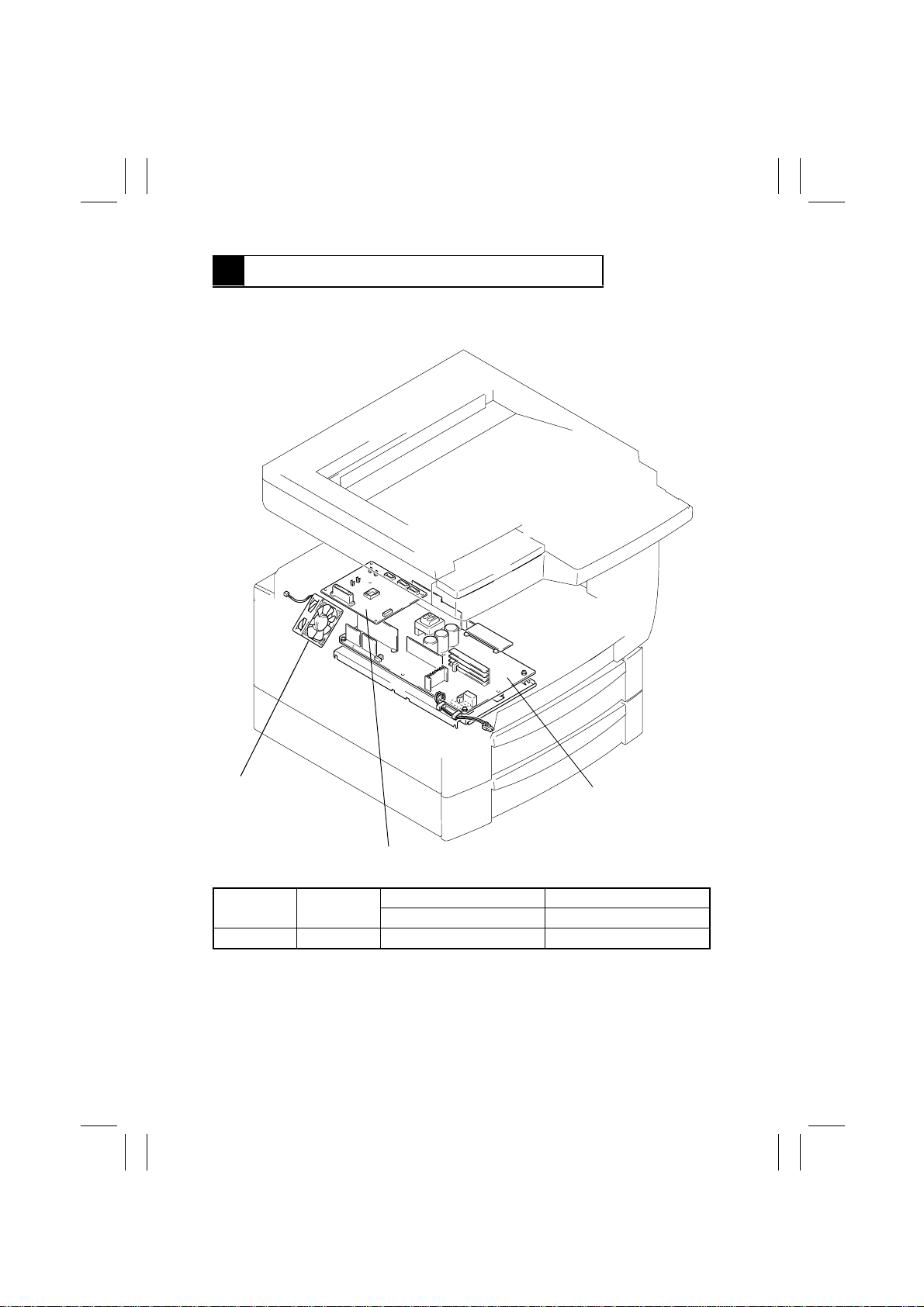
22 POWER UNIT COOLING FAN MOTOR
•
The Power Unit Cooling Fan Motor prevents the temperature at the Power Supply Unit
and the Polygon Motor in the PH from rising inordinately.
Power Unit Cooling
Fan Motor (M4)
Master Board (PWB-A)
Electrical
Component
M4 PJ6A-2 DC24V DC10V
Control
Signal
While Main Motor is Turning In Standby
Full speed Half speed
Power Supply Unit 1 (PU1)
M-50
1171M034AA
 Loading...