

Page 1

17500XX-001
1750061-001A
Page 2

Trademarks
The following are registered trademarks of MINOLTA-QMS, Inc.: QMS and the
MINOLTA-QMS logo. Minolta, and PagePro are trademarks of Minolta Co., Ltd.
Other product names mentioned in this guide may also be trademarks or
registered trademarks of their respective owners.
Proprietary Statement
The digitally encoded software included with your printer is Copyrighted © 2002
by MINOLTA-QMS, Inc. All Rights Reserved. This software may not be
reproduced, modified, displayed, transferred, or copied in any form or in any
manner or on
any media, in whole or in part, without the express written permission of
MINOLTA-QMS, Inc.
Copyright Notice
This manual is Copyrighted © 2003 by MINOLTA-QMS, Inc., One Magnum Pass,
Mobile, AL 36618. All Rights Reserved. This document may not be copied, in
whole or part, nor transferred to any other media or language, without written
permission of MINOLTA-QMS, Inc.
Manual Notice
MINOLTA-QMS, Inc. reserves the right to make changes to this manual and to the equip-
ment described herein without notice. Considerable effort has been made to
ensure that this manual is free of inaccuracies and omissions. However,
Inc. makes no warranty of any kind including, but not limited to, any implied warranties of merchantability and fitness for a particular purpose with regard to this
manual.
tained in this manual or for incidental, special, or consequential damages arising
out of the furnishing of this manual, or the use of this manual in operating the
equipment, or in connection with the performance of the equipment when so operated.
MINOLTA-QMS, Inc. assumes no responsibility for, or liability for, errors con-
MINOLTA-QMS,
2
Page 3
1. SAFETY PRECAUTIONS FOR INSPECTION AND SERVICE
• When performing inspection and service procedures, observe the following precautions
to prevent accidents and ensure utmost safety.
✽ Depending on the model, some of the precautions given in the following do not apply.
• Different markings are used to denote specific meanings as detailed below.
WARNING
• Indicates a potentially hazardous situation which, if not avoided, could result in death or
serious injury.
CAUTION
• Indicates a potentially hazardous situation which, if not avoided, may result in minor or
moderate injury. It may also be used to alert against unsafe practices.
• The following graphic symbols are used to give instructions that need to be observed.
Used to call the service technician attention to what is graphically represented
inside the marking (including a warning).
Used to prohibit the service technician from doing what is graphically represented
inside the marking.
Used to instruct the service technician to do what is graphically represented
inside the marking.
1-1. Warning
1. Always observe precautions.
• Parts requiring special attention in this product will include a label containing
the mark shown on the left plus precautionary notes. Be sure to observe the
precautions.
• Be sure to observe the “Safety Information” given in the Operator’s Manual.
WARNING
3
Page 4
WARNING
2. Before starting the procedures, be sure to unplug the power cord.
• This product contains a high-voltage unit and a circuit with a large current
capacity that may cause an electric shock or burn.
• The product also contains parts that can jerk suddenly and cause injury.
• If this product uses a laser, laser beam leakage may cause eye damage or
blindness.
3. Do not throw toner or the toner bottle into a fire.
• Do not throw toner or the Toner Bottle (Imaging Cartridge, Toner Cartridge) into
a fire. Toner expelled from the fire may cause burns.
4. Use the specified parts.
• For replacement parts, always use the genuine parts specified in the manufacturer’s parts manual. Installing a wrong or unauthorized part could cause
dielectric breakdown, overload, or undermine safety devices resulting in possible electric shock or fire.
• Replace a blown electrical fuse or thermal fuse with its corresponding genuine
part specified in the manufacturer’s parts manual. Installing a fuse of a different
make or rating could lead to a possible fire. If a thermal fuse blows frequently,
the temperature control system may have a problem and action must be taken
to eliminate the cause of the problem.
5. Handle the power cord with care and never use a multiple outlet.
• Do not break, crush or otherwise damage the power cord. Placing a heavy
object on the power cord, or pulling or bending it may damage it, resulting in a
possible fire or electric shock.
• Do not use a multiple outlet to which any other appliance or machine is connected.
• Be sure the power outlet meets or exceeds the specified capacity.
• Use only the power cord supplied in the package. If a power cord is not supplied, only use the power cord and plug that is specified in POWER CORD
INSTRUCTION. Failure to use this cord could result in a fire or electrical shock.
• Use the power cord supplied in the package only for this machine and NEVER
use it for any other product. Failure to observe this precaution could result in a
fire or electrical shock.
6. Be careful with the high-voltage parts.
• A part marked with the symbol shown on the left carries a high voltage. Touching it could result in an electric shock or burn. Be sure to unplug the power cord
before servicing this part or the parts near it.
7. Do not work with wet hands.
• Do not unplug or plug in the power cord, or perform any kind of service or
inspection with wet hands. Doing so could result in an electric shock.
4
Page 5
WARNING
8. Do not touch a high-temperature part.
• A part marked with the symbol shown on the left and other parts such as the
exposure lamp and fusing roller can be very hot while the machine is energized. Touching them may result in a burn.
• Wait until these parts have cooled down before replacing them or any surrounding parts.
9. Maintain a grounded connection at all times.
• Connect the power cord to an electrical outlet that is equipped with a grounding
terminal.
10. Do not remodel the product.
• Modifying this product in a manner not authorized by the manufacturer may
result in a fire or electric shock. If this product uses a laser, laser beam leakage
may cause eye damage or blindness.
11. Restore all parts and harnesses to their original positions.
• To promote safety and prevent product damage, make sure the harnesses are
returned to their original positions and properly secured in their clamps and
saddles in order to avoid hot parts, high-voltage parts, sharp edges, or being
crushed.
• To promote safety, make sure that all tubing and other insulating materials are
returned to their original positions. Make sure that floating components
mounted on the circuit boards are at their correct distance and position off the
boards.
1-2. Caution
1. Precautions for Service Jobs.
• A star washer and spring washer, if used originally, must be reinstalled. Omitting them may result in contact failure which could cause an electric shock or
fire.
• When reassembling parts, make sure that the correct screws (size, type) are
used in the correct places. Using the wrong screw could lead to stripped
threads, poorly secured parts, poor insulating or grounding, and result in a malfunction, electric shock or injury.
• Take great care to avoid personal injury from possible burrs and sharp edges
on the parts, frames and chassis of the product.
• When moving the product or removing an option, use care not to injure your
back or allow your hands to be caught in mechanisms.
CAUTION
5
Page 6
CAUTION
2. Precautions for Servicing with Covers and Parts Removed.
• Wherever feasible, keep all parts and covers mounted when energizing the
product.
• If energizing the product with a cover removed is absolutely unavoidable, do
not touch any exposed live parts and use care not to allow your clothing to be
caught in the moving parts. Never leave a product in this condition unattended.
• Never place disassembled parts or a container of liquid on the product. Parts
falling into, or the liquid spilling inside, the mechanism could result in an electric shock or fire.
• Never use a flammable spray near the product. This could result in a fire.
• Make sure the power cord is unplugged before removing or installing circuit
boards or plugging in or unplugging connectors.
• Always use the interlock switch actuating jig to actuate an interlock switch
when a cover is opened or removed. The use of folded paper or some other
object may damage the interlock switch mechanism, possibly resulting in an
electric shock, injury or blindness.
3. Precautions for the Working Environment.
• The product must be placed on a flat, level surface that is stable and secure.
• Never place this product or its parts on an unsteady or tilting workbench when
servicing.
• Provide good ventilation at regular intervals if a service job must be done in a
confined space for a long period of time.
• Avoid dusty locations and places exposed to oil or steam.
• Avoid working positions that may block the ventilation ports of the product.
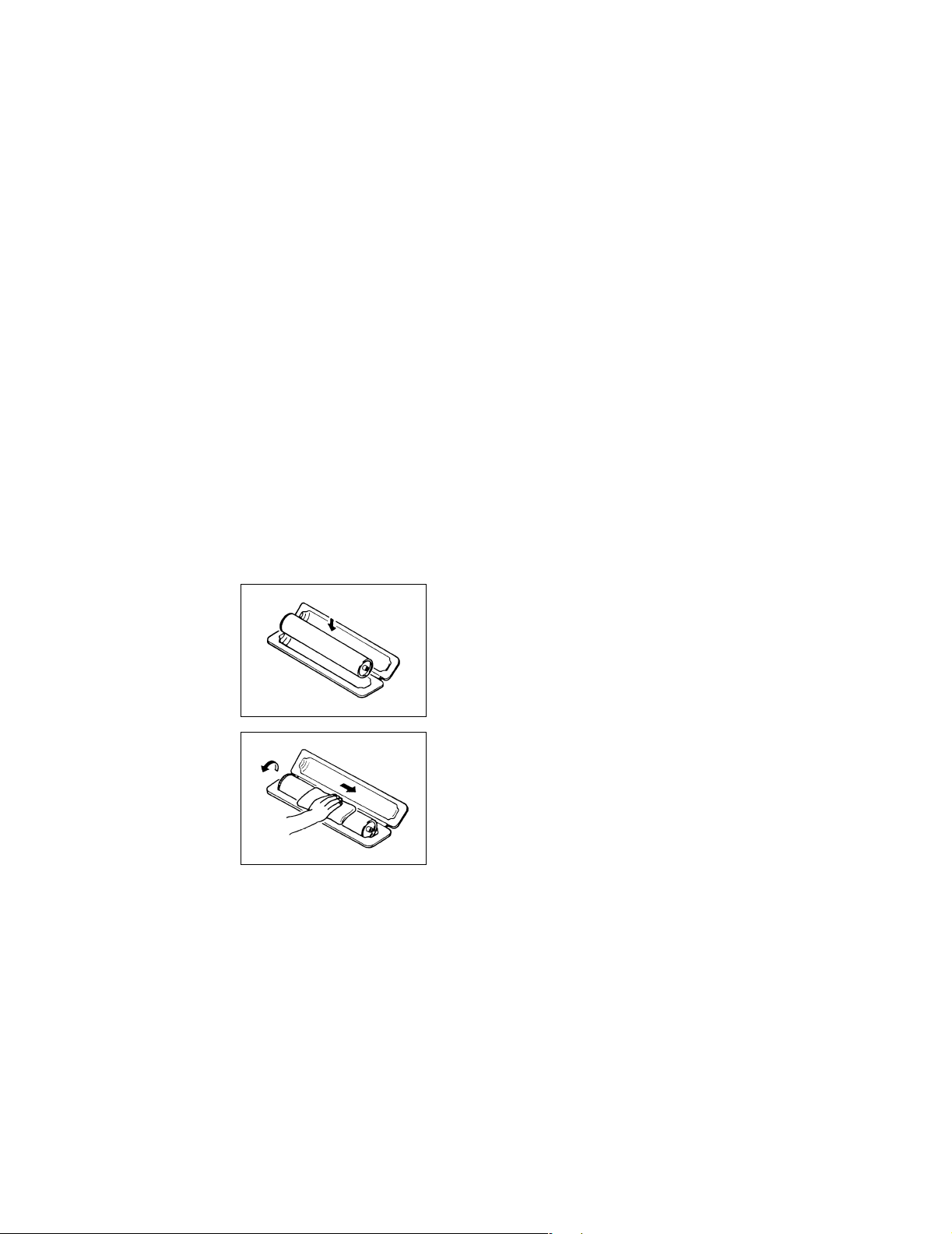
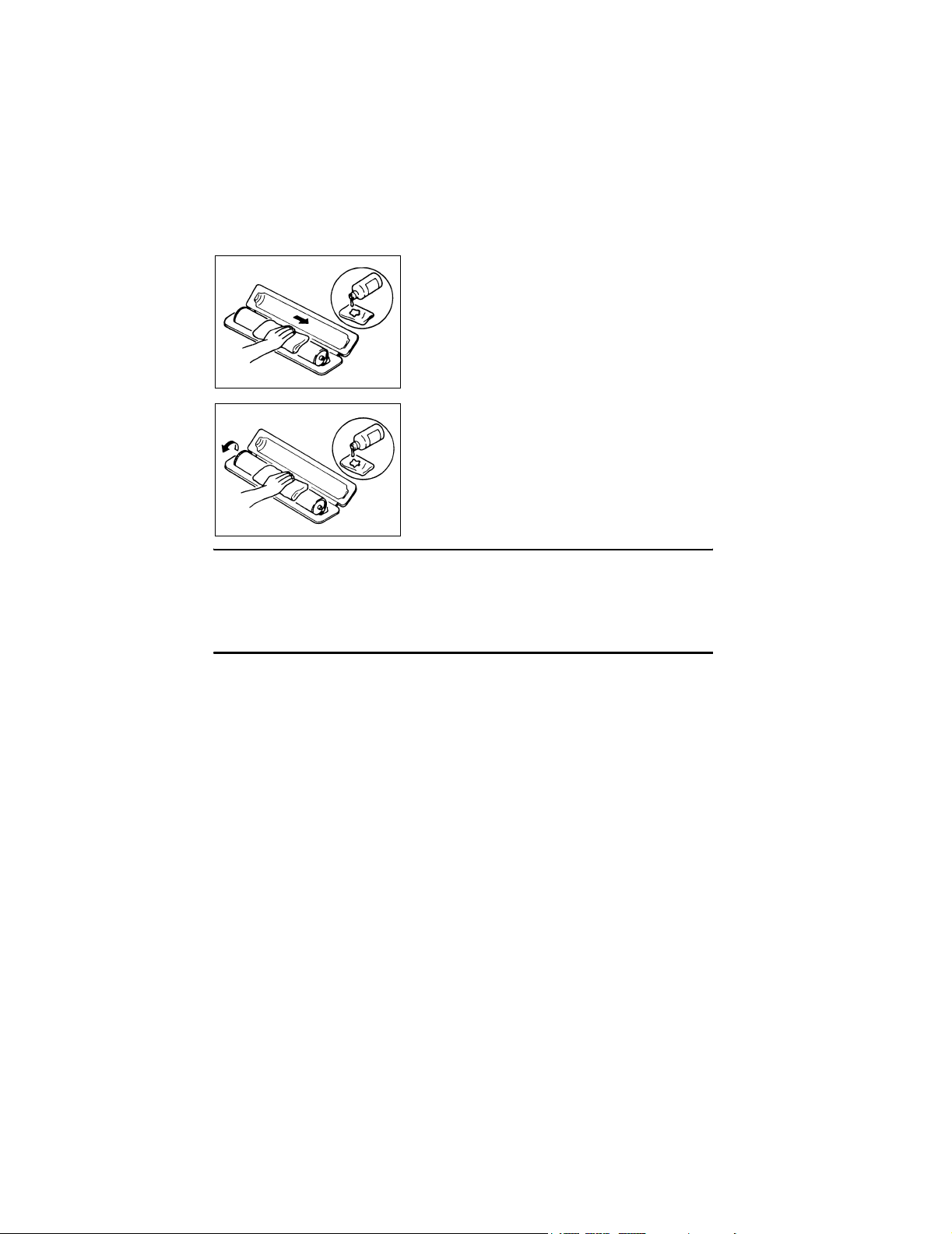
4. Precautions for Handling Batteries. (Lithium, Nickel-Cadmium, etc.)
• Replace a rundown battery with the same type as specified in the manufacturer’s parts manual.
• Before installing a new battery, make sure of the correct polarity of the installation or the battery could burst.
• Dispose of used batteries according to the local regulations. Never dispose of
them at the user’s premises or attempt to try to discharge one.
5. Precautions for the Laser Beam. (Only for Products Employing a Laser)
• Removing the cover marked with the caution label could lead to possible exposure to the laser beam, resulting in eye damage or blindness. Be sure to
unplug the power cord before removing this cover.
• If removing this cover while the power is ON is unavoidable, be sure to wear
protective laser goggles that meet specifications.
• Make sure that no one enters the room when the machine is in this condition.
• When handling the laser unit, observe the “Precautions for Handling Laser
Equipment.”
6. Precautions for storing the toner or imaging cartridge.
• Be sure to keep the toner or imaging cartridge out of the reach of children.
Licking the imaging cartridge or ingesting its contents is harmful to your health.
6
Page 7

1-3. Used Batteries Precautions
ALL Areas
Danger of explosion if battery is incorrectly replaced.
Replace only with the same or equivalent type recommended by the manufacturer.
Dispose of used batteries according to the manufacturer’s instructions.
Germany
Explosionsgefahr bei unsachgemäßem Austausch der Batterie.
Ersatz nur durch denselben oder einen vom Hersteller empfohlenen gleichwertigen Typ.
Entsorgung gebrauchter Batterien nach Angaben des Herstellers.
France
Il y a danger d’explosion s’il y a remplacement incorrect de la batterie.
Remplacer uniquement avec une batterie du même type ou d’un type équivalent recommandé par le constructeur.
Mettre au rebut les batteries usagées conformément aux instructions du fabricant.
Denmark
Lithiumbatteri - Eksplosionsfare ved fejlagtig håndtering.
Udskiftning må kun ske med batteri af samme fabrikat og type.
Levér det brugte batteri tilbage til leverandøren.
Finland, Sweden
Paristo voi räjähtää, jos se on virheellisesti asennettu.
Vaihda paristo ainoastaan laitevalmistajan suosittelemaan tyyppiin.
Hävitä käytetty paristo valmistajan ohjeiden mukaisesti.
CAUTION
VORSICHT!
ATT ENTI ON
ADVARSEL!
VAR OlTU S
Explosionsfara vid felaktigt batteribyte.
Använd samma batterityp eller en ekvivalent typ som rekommenderas av apparattillverkaren.
Kassera använt batteri enligt fabrikantens instruktion.
Norway
Eksplosjonsfare ved feilaktig skifte av batteri.
Benytt samme batteritype eller en tilsvarende type anbefalt av apparatfabrikanten.
Brukte batterier kasseres i henhold til fabrikantens instruksjoner.
VARNING
ADVARSEL
7
Page 8

1-4. Other Precautions
• When handling circuit boards, observe the “HANDLING of PWBs”.
• The PC Drum is a very delicate component. Observe the precautions given in “HANDLING OF THE PC DRUM” because mishandling may result in serious image problems.
• Note that replacement of a circuit board may call for readjustments or resetting of particular items, or software installation.
1-5. Precautions for Service
• When performing inspection and service procedures, observe the following precautions
to prevent mishandling of the machine and its parts.
✽ Depending on the model, some of the precautions given in the following do not apply.
1. Precautions Before Service
• When the user is using a word processor or personal computer from a wall outlet of the
same line, take necessary steps to prevent the circuit breaker from opening due to overloads.
• Never disturb the LAN by breaking or making a network connection, altering termination,
installing or removing networking hardware or software, or shutting down networked
devices without the knowledge and express permission of the network administrator or
the shop supervisor.
2. How to Use this Book
DIS/REASSEMBLY, ADJUSTMENT
• To reassemble the product, reverse the order of disassembly unless otherwise specified.
TROUBLESHOOTING
• If a component on a PWB or any other functional unit including a motor is defective, the
text only instructs you to replace the whole PWB or functional unit and does not give troubleshooting procedures applicable within the defective unit.
• All troubleshooting procedures contained herein assume that there are no breaks in the
harnesses and cords and all connectors are plugged into the right positions.
• The procedures preclude possible malfunctions due to noise and other external causes.
3. Precautions for Service
• Keep all disassembled parts in good order and keep tools under control so that none will
be lost or damaged.
• After completing a service job, perform a safety check. Make sure that all parts, wiring
and screws are returned to their original positions.
• Do not pull out the toner hopper while the toner bottle is turning. This could result in a
damaged motor or locking mechanism.
• If the product is to be run with the front door open, make sure that the toner hopper is in
the locked position.
• Do not use an air gun or vacuum cleaner for cleaning the ATDC Sensor and other sensors, as they can cause electrostatic destruction. Use a blower brush and cloth. If a unit
containing these sensors is to be cleaned, first remove the sensors from the unit.
8
Page 9

4. Precautions for Dis/Reassembly
• Be sure to unplug the printer from the outlet before attempting to service the printer.
• The basic rule is not to operate the printer anytime during disassembly. If it is absolutely
necessary to run the printer with its covers removed, use care not to allow your clothing
to be caught in revolving parts such as the timing belt and gears.
• Before attempting to replace parts and unplug connectors, make sure that the power
cord of the printer has been unplugged from the wall outlet.
• Be sure to use the Interlock Switch Actuating Jig whenever it is necessary to actuate the
Interlock Switch with the covers left open or removed.
• While the product is energized, do not unplug or plug connectors into the circuit boards
or harnesses.
• Never use flammable sprays near the printer.
• A used battery should be disposed of according to the local regulations and never be discarded casually or left unattended at the user’s premises.
• When reassembling parts, make sure that the correct screws (size, type) and toothed
washer are used in the correct places.
5. Precautions for Circuit Inspection
• Never create a closed circuit across connector pins except those specified in the text and
on the printed circuit.
• When creating a closed circuit and measuring a voltage across connector pins specified
in the text, be sure to use the GND wire.
6. Handling of PWBs
During Transportation/Storage
• During transportation or when in storage, new P.W. Boards must not be indiscriminately
removed from their protective conductive bags.
• Do not store or place P.W. Boards in a location exposed to direct sunlight and high temperature.
• When it becomes absolutely necessary to remove a Board from its conductive bag or
case, always place it on its conductive mat in an area as free as possible from static electricity.
• Do not touch the pins of the ICs with your bare hands.
• Protect the PWBs from any external force so that they are not bent or damaged.
During Inspection/Replacement
• Avoid checking the IC directly with a multimeter; use connectors on the Board.
• Never create a closed circuit across IC pins with a metal tool.
• Before unplugging connectors from the P.W. Boards, make sure that the power cord has
been unplugged from the outlet.
• When removing a Board from its conductive bag or conductive case, do not touch the
pins of the ICs or the printed pattern. Place it in position by holding only the edges of the
Board.
• When touching the PWB, wear a wrist strap and connect its cord to a securely grounded
place whenever possible. If you cannot wear a wrist strap, touch a metal part to discharge static electricity before touching the PWB.
• Note that replacement of a PWB may call for readjustments or resetting of particular
items.
7. Handling of Other Parts
• The magnet roller generates a strong magnetic field. Do not bring it near a watch, floppy
disk, magnetic card, or CRT tube.
9
Page 10
8. Handling of the PC Drum
✽ Only for Products Not Employing an Imaging Cartridge.
During Transportation/Storage
• Use the specified carton whenever moving or storing the PC Drum.
• The storage temperature is in the range between –20°C and +40°C.
• In summer, avoid leaving the PC Drum in a car for a long time.
Handling
• Ensure that the correct PC Drum is used.
• Whenever the PC Drum has been removed from the printer, store it in its carton or protect it with a Drum Cloth.
• The PC Drum exhibits greatest light fatigue after being exposed to strong light over an
extended period of time. Never, therefore, expose it to direct sunlight.
• Use care not to contaminate the surface of the PC Drum with oil-base solvent, fingerprints, and other foreign matter.
• Do not scratch the surface of the PC Drum.
• Do not apply chemicals to the surface of the PC Drum.
• Do not attempt to wipe clean the surface of the PC Drum.
If, however, the surface is contaminated with fingerprints, clean it using the following procedure.
A. Place the PC Drum into one half of its carton.
C4134S024AA
C4134S025AA
B. Gently wipe the residual toner off the surface of the
PC Drum with a dry, Dust-Free Cotton Pad.
• Turn the PC Drum so that the area of its surface on
which the line of toner left by the Cleaning Blade is
present is facing straight up. Wipe the surface in one
continuous movement from the rear edge of the PC
Drum to the front edge and off the surface of the PC
Drum.
• Turn the PC Drum slightly and wipe the newly
exposed surface area with a CLEAN face of the
Dust-Free Cotton Pad. Repeat this procedure until
the entire surface of the PC Drum has been thoroughly cleaned.
✽ At this time, always use a CLEAN face of the dry
Dust-Free Cotton Pad until no toner is evident on the
face of the Pad after wiping.
10
Page 11
C. Soak a small amount of either ethyl alcohol or iso-
propyl alcohol into a clean, unused Dust-Free Cotton Pad which has been folded over into quarters.
Now, wipe the surface of the PC Drum in one continuous movement from its rear edge to its front
edge and off its surface one to two times.
✽ Never move the Pad back and forth.
C4134S026AA
D. Using the SAME face of the Pad, repeat the proce-
dure explained in the latter half of step 3 until the
entire surface of the PC Drum has been wiped.
Always OVERLAP the areas when wiping. Two
complete turns of the PC Drum would be appropriate for cleaning.
C4134S027AA
NOTES
• Even when the PC Drum is only locally dirtied, wipe the entire surface.
• Do not expose the PC Drum to direct sunlight. Clean it as quickly as possible even under
interior illumination.
• If dirt remains after cleaning, repeat the entire procedure from the beginning one more
time.
9. Handling of the Imaging Cartridge and Print Unit
✽ Only for Products Employing an Imaging Cartridge and Print Unit.
During Transportation/Storage
• The storage temperature is in the range between –20 °C and +40 °C.
• In summer, avoid leaving the Imaging Cartridge and Print Unit in a car for a long time.
Handling
• Store the Imaging Cartridge and Print Unit in a place that is not exposed to direct sunlight.
Precautionary Information on the PC Drum Inside the Imaging Cartridge and Print Unit
• Use care not to contaminate the surface of the PC Drum with oil-base solvent, fingerprints, and other foreign matter.
• Do not scratch the surface of the PC Drum.
• Do not attempt to wipe clean the surface of the PC Drum.
11
Page 12
1-6. Safety information
(1) Laser Safety
• This is a digital machine certified as a class 1 laser product. There is no possibility of
danger from a laser, provided the machine is serviced according to the instruction in this
manual.
(2) Internal Laser Radiation
semiconductor laser
Maximum power of the laser diode 15 mW
Maximum average radiation power(*) 7.351 µW
Wavelength 770-800 nm
*:at laser aperture of the Print Head Unit
• This product employs a Class 3b laser diode that emits an invisible laser beam. The laser
diode and the scanning polygon mirror are incorporated in the print head unit.
• The print head unit is NOT A FIELD SERVICE ITEM. Therefore, the print head unit
should not be opened under any circumstances.
Laser Aperture of
the Print Head Unit
4134G001AA
This figure shows the view inside the Top Cover with the Toner
Cartridge and the Drum Cartridge removed.
12
Page 13

the U.S.A., Canada
(CDRH Regulation)
• This machine is certified as a Class I Laser product under Radiation Performance Standard according to the Food, Drug and Cosmetic Act of 1990. Compliance is mandatory
for Laser products marketed in the United States and is reported to the Center for
Devices and Radiological Health (CDRH) of the U.S. Food and Drug Administration of
the U.S. Department of Health and Human Services (DHHS). This means that the device
does not produce hazardous laser radiation.
• The label shown to page 13 indicates compliance with the CDRH regulations and must
be attached to laser products marketed in the United States.
.
CAUTION
Use of controls, adjustments or performance of procedures other than those specified in
this manual may result in hazardous radiation exposure.
semiconductor laser
Maximum power of the laser diode 15 mW
Wavelength 770-800 nm
All Areas
CAUTION
Use of controls, adjustments or performance of procedures other than those specified in
this manual may result in hazardous radiation exposure.
semiconductor laser
Maximum power of the laser diode 15 mW
Wavelength 770-800 nm
Denmark
ADVARSEL
Usynlig laserstråling ved åbning, når sikkerhedsafbrydere er ude af funktion.
Undgå udsættelse for stråling. Klasse 1 laser produkt der opfylder IEC60825 sikkerheds
kravene.
halvlederlaser
Laserdiodens højeste styrke 15 mW
bølgelængden 770-800 nm
13
Page 14

Finland, Sweden
LUOKAN 1 LASERLAITE
KLASS 1 LASER APPARAT
VAROITUS!
Laitteen käyttäminen muulla kuin tässä käyttöohjeessa mainitulla tavalla saattaa altistaa
käyttäjän turvallisuusluokan 1 ylittävälle näkymättömälle lasersäteilylle.
puolijohdelaser
Laserdiodin suurin teho 15 mW
aallonpituus 770-800 nm
VARNING!
Om apparaten används på annat sätt än i denna bruksanvisning specificerats, kan
användaren utsättas för osynlig laserstrålning, som överskrider gränsen för laserklass 1.
halvledarlaser
Den maximala effekten för laserdioden 15 mW
våglängden 770-800 nm
VARO!
Avattaessa ja suojalukitus ohitettaessa olet alttiina näkymättomälle lasersäteilylle. Älä
katso säteeseen.
VARNING!
Osynlig laserstråining när denna del är öppnad och spärren är urkopplad. Betrakta ej
stråien.
Norway
ADVERSEL
Dersom apparatet brukes på annen måte enn spesifisert i denne bruksanvisning, kan
brukeren utsettes för unsynlig laserstrålning, som overskrider grensen for laser klass 1.
halvleder laser
Maksimal effekt till laserdiode 15 mW
bølgelengde 770-800 nm
14
Page 15
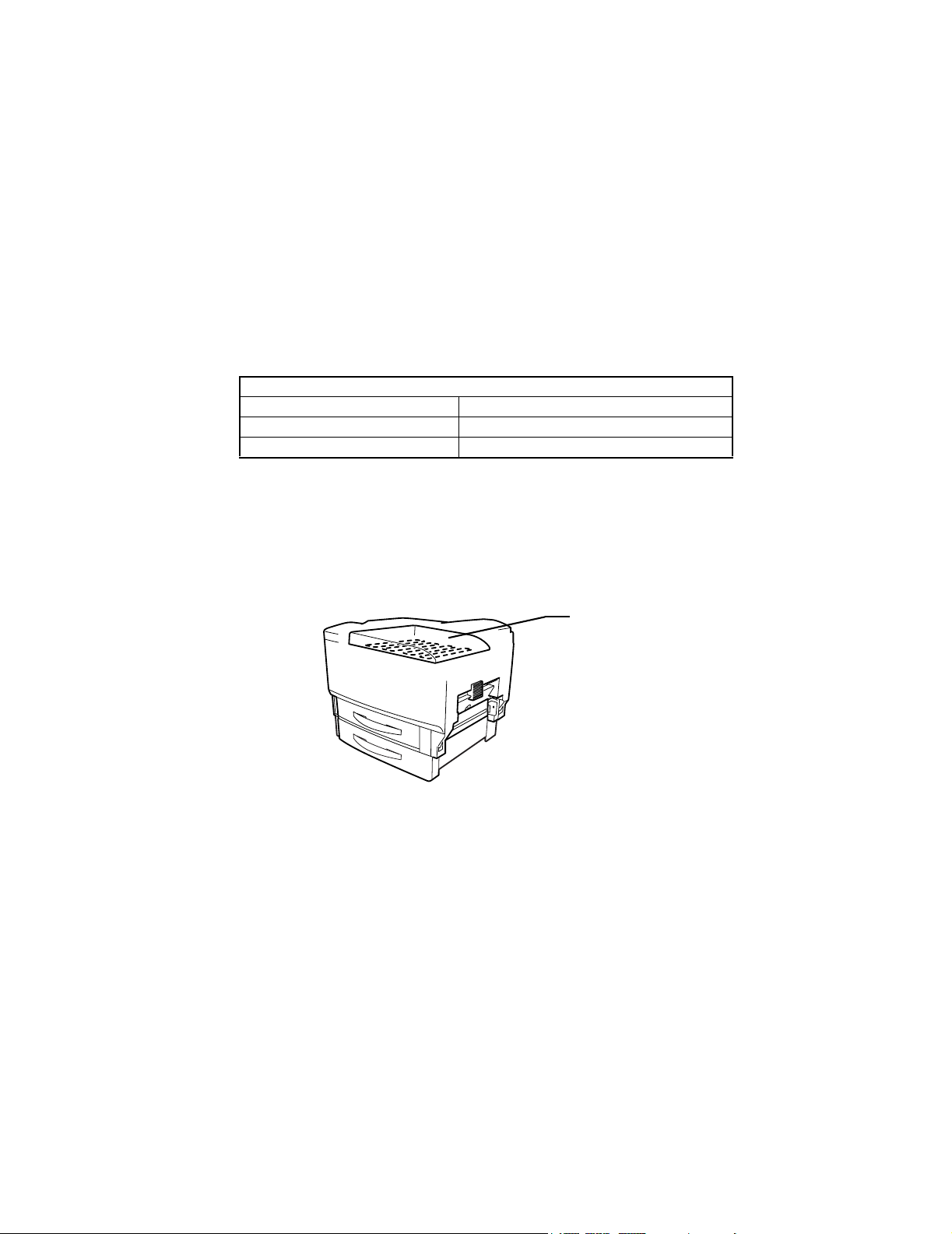
1-7. Laser Safety Label
• A laser safety label is attached to the the machine as shown below.
C4134o118AA
C4134o146AB
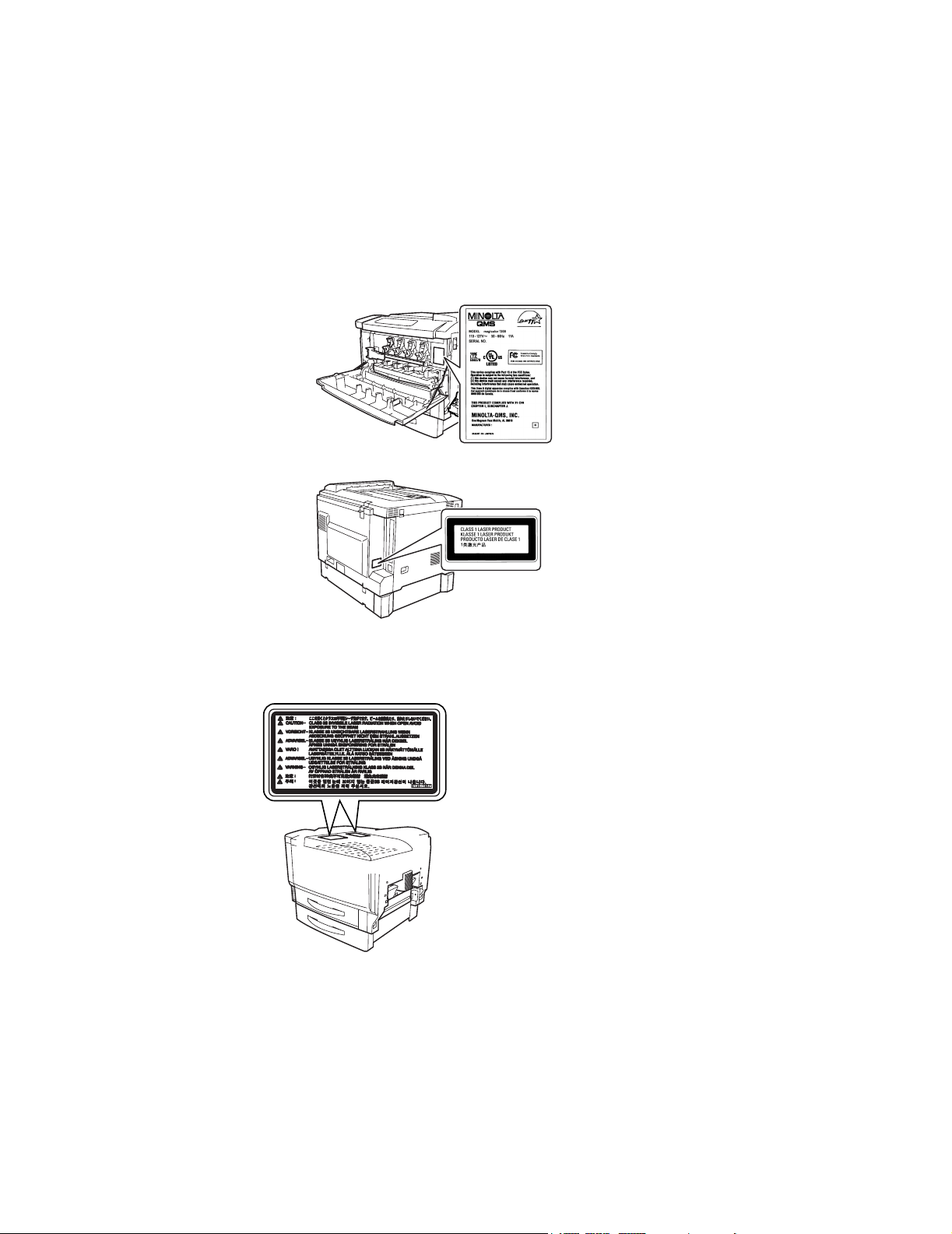
1-8. Laser Caution Label
• A laser caution label is attached to the inside of the machine as shown below.
15
C4134o066AD
Page 16

1-9. PRECAUTIONS FOR HANDLING THE LASER EQUIPMENT
• When laser protective goggles are to be used, select ones with a lens conforming to the
above specifications.
• When a disassembly job needs to be performed in the laser beam path, such as when
working around the printerhead and PC Drum, be sure first to turn the printer OFF.
• If the job requires that the printer be left ON, take off your watch and ring and wear laser
protective goggles.
• A highly reflective tool can be dangerous if it is brought into the laser beam path. Use
utmost care when handling tools on the user’s premises.
• The Print Head are not to be disassembled or adjusted in the field. Replace the Unit or
Assembly including the Control Board. Therefore, remove the Laser Diode, and do not
perform Control Board trimmer adjustment.
16
Page 17

CONTENTS
17
Page 18

18
Page 19

SAFETY PRECAUTIONS FOR INSPECTION AND SERVICE 3
Warning 3
Caution 5
Used Batteries Precautions 7
Other Precautions 8
Precautions for Service 8
Safety information 12
Laser Safety Label 15
Laser Caution Label 15
PRECAUTIONS FOR HANDLING THE LASER EQUIPMENT 16
CONTENTS 17
GENERAL 23
SPECIFICATIONS 25
Precautions for Installation 28
Installation Site 28
Power Source 28
Space Requirements 29
Precautions for Use 30
To ensure that the printer is used in an optimum condition 30
Operating Environment 30
Power Requirements 30
Other Precautions 30
Handling Consumables 31
List of Names 32
MECHANICAL/ELECTRICAL 33
Cross-Section View 35
Electrical Parts Layout 36
Printer 36
Controller 38
Operating sequence 39
Image stabilization control 40
Image Stabilization Control 40
Operation Timing 41
Image stabilization control flow 42
AIDC Sensor 43
Print Head (PH) 44
System Configuration 44
Laser exposure process 45
Laser emission timing 46
Laser emission area 47
Cooling of Print Head Unit 48
Print Unit 49
System Configuration 49
Drive Print Unit 50
Print Unit Detection 51
Toner Cartridge detection 51
PC Drum 52
19
Page 20

PC Drum Charging 53
Developing Section 55
Cleaner 60
IMAGE TRANSFER SECTION 61
Construction of Transfer Belt Unit 61
Transfer Belt Unit Drive 62
New Transfer Belt Unit Detection 62
Transfer Belt Unit Set Detection 63
Color Shift Detection 64
Color Shift Correction 65
First Image Transfer Roller Pressure/Retraction Mechanism 67
2nd Image Transfer Pressure/Retraction Mechanism 69
2nd Image Transfer 70
2nd Image Transfer 70
Image Transfer ATVC Control 71
Temperature/Humidity Sensor 72
Transfer Belt Cleaning Mechanism 73
Cleaning the 2nd Image Transfer Roller 73
Waste Toner Box 74
Fusing Section 75
Drive of Fuser Unit 75
Fuser Unit Drive 76
Control of Loop Before Fusing 76
New Fuser Unit Detection 77
Pressure of Fusing Roller 77
Temperature Control 78
Paper Take-Up 82
1st Drawer 82
2nd Drawer (Add-on Cassette: Optional) 86
Manual Bypass Paper Take-Up Unit (optional) 91
Transport Section 92
Synchronizing Roller Drive 92
Image Transfer Failure Prevention During High Humidity 92
Switch of system speed 93
OHP Detecting 93
Duplex Unit (optional) 94
Drive of Duplex Unit 94
PAPER FEEDING SYSTEM 95
MAINTENANCE 99
Maintenance Schedule List 101
Guidelines for Life-time Expected Values by Unit 103
Disassembly/Reassembly and Cleaning 105
Replacing the Units 110
ASSEMBLY/
DISASSEMBLY 125
SERVICE INSTRUCTIONS 127
IDENTIFICATION OF FUSES 127
20
Page 21

PARTS WHICH MUST NOT BE TOUCHED 128
ASSEMBLY/DISASSEMBLY 129
Doors, Covers and Exterior Parts 129
Removing Doors, Covers and Exterior Parts 130
Removing Circuit Boards and other Electrical Components 134
Removing Units 149
CLEANING AND DISASSEMBLY OF THE ENGINE PARTS 158
Disassembing the Manual Feed Unit (optional) 167
Disassembling the Duplex Unit (optional) 170
Disassembling the Paper Feed Unit (optional) 175
CONTROL PANEL
Panel Menu Operations 177
Control Panel 179
Names and Functions of Control Panel Keys 179
Control Panel Display 181
Control Panel Message 182
Canceling a Print Job 186
Panel Menu 187
Summary of Panel Menu 187
Sub-menu 188
Contents of Panel Menu 193
MAINTENANCE MODE 198
SETTING THE MAINTENANCE MODE 198
Summary of the Maintenance Mode 199
Maintenance Menu 199
CONTENTS OF MAINTENANCE MODE 200
UPDATE FIRMWARE 202
Update using IEEE-1284 Parallel Cable 202
Network Cable (FTP) Update 204
WHEN UPDATE FAILS 206
TROUBLESHOOTING 207
INTRODUCTION 209
Checking the electrical components 209
System Control Block Diagram 213
Jam 214
Initial Check Items 214
Misfeed Display 215
Misfeed Detecting Sensor Layout 216
Misfeed Detection Timing/Troubleshooting Procedures 217
MALFUNCTIONS 227
MALFUNCTION CODES 227
Malfunction Detection Timing and Troubleshooting Procedure 230
Power Supply-Related Malfunctions 248
Printer is not energized at all 248
Other Precautions 249
Emergency Stop Error 249
Print Prohibition Error 250
21
Page 22

Warning Error 250
Image Problem 252
Troubleshooting Procedure by a Particular Image Quality Problem 252
22
Page 23

GENERAL
23
Page 24

24
Page 25

1. SPECIFICATIONS
Printer
Desktop tandem color laser beam printer
TYPE
Printing System
Exposure System
Printing Density
Paper Size
Paper Type
Fast Print Time
Multi-page Print Speed
Warm-Up Time
System Speed
Paper Feeding System
Paper Ejection Method
Charging System
Developing System
Image Transfer System
PC Drum
PC Drum Cleaning
Paper Separator System
Fusing System
Dimensions
Weight
Power Requirements
Max. Power
Consumption
Operating Noise
:
Semiconductor laser and electrostatic image transfer to plain
:
paper
:
Laser diode and polygon mirror
:
600 × 600 dpi
:
1st Drawer: A5, ISO B5, JIS B5, A4, B4, A3, Oversized,
Folio, SP Folio, Statement, Executive, Government Letter,
Letter, Government Legal, Legal, 11 × 17, 8 × 10, Foolscap,
12 × 18, Com10, DL, Monarch, C5, C6, Chokei #3, Chokei
#4, Chinese 8K, Chinese 16K, Chinese 32K, Japanese
official postcards, Irregular size (90 × 148 mm - 311 × 457
mm)
2nd Drawer: JIS B5, A4, B4, A3, Letter, Legal, Ledger
1st Drawer: plain paper, recycled paper (64-90 g/m
:
paper, envelopes, label sheets, thick paper (91-210 g/m
and japanese official postcards
2nd Drawer: plain paper, recycled paper (64-90 g/m
:
For monochrome printing: 13 sec. (for A4C, 1st Drawer)
For full color printing: 16 sec. (for A4C, 1st Drawer)
:
21.6 sheets/minute (for A4C, 1st Drawer)
20.5 sheets/minute (for Letter C, 1st Drawer)
:
Within 99.9 seconds (at a room temperature of 23°C and at
the rated voltage)
:
90.3 mm/sec
:
2-way system (maximum 5-way) *1
250 sheets of plain paper, recycled paper, 10 envelopes, 50
sheets of thick paper, label sheets, OHP transparencies,
japanese official postcards
2nd Drawer (500 sheets)
Expandable to 5-way system by installing the optional 3rd
and 4th Drawer paper cassettes
:
Face-down (tray capacity: 250 sheets)
:
DC comb electrode Scorotron System
:
Single-element developing system
:
Intermediate Image Transfer Belt System
:
OPC
:
Blade system
:
Curvature separation + charge-neutralizing system
:
Heated roller fusing system (Oil is not used)
:
628 mm (W) × 594 mm (D) × 564 mm (H)
:
58.6 kg (with PU/TC)
:
120 V, 60 Hz ± 3 Hz, 12 A
220-240 V, 50-60 Hz ± 3 Hz, 6.5 A
:
1,400 W
:
During standby:40 dB (A) or less
During printing: 50 dB (A) or less (1st Drawer), 53 dB (A) or
less (2nd Drawer)
2
), OHP
2
)
2
),
25
Page 26

Environmental
Conditions
Option
Lower Feeder Unit (optional)
Name
Paper Type
Paper Size
Capacity
Paper Feed Separator
Power Requirements
Size
Weight
Duplex Unit Kit (optional)
Name
Paper Type
Paper Size
Print speed (doublesided printing)
Paper transfer baseline
Power Requirements
Size
Weight
::10-32.5 °C
15-85%
Paper Feed Unit, Duplex Unit Kit (with Manual Feed Unit)
Lower Feeder Unit
:
Plain paper (64-90 g/m
:
:
JIS B5, A4, B4, A3, Letter, Legal, Ledger
:
500 sheets (64 g/m
:
Torque Limiter Method
:
Supplied by main unit
:
575 mm (W) × 568 mm (D) × 127 mm (H)
:
8.5 kg
Duplex Unit
:
Plain paper (64-90 g/m
:
:
A5, JIS B5, A4, B4, A3, Folio, SP Folio, Statement,
2
), recycled paper (64-90 g/m2),
2
)
2
), recycled paper (64-90 g/m2)
Executive, Government Letter, Letter, Government Legal,
Legal, Ledger, 8 × 10, Foolscap, Irregular size (90 × 148 mm
- 297 × 432 mm)
:
17.5 pages/minute (for A4C, 1st Drawer)
17.0 pages/minute (for Letter C, 1st Drawer)
:
Center baseline
:
Supplied by main unit
:
65 mm (W) × 445 mm (D) × 311 mm (H)
:
2.1 kg
Name
Paper Type
Paper Size
Capacity
Power Requirements
Size
Weight
Manual Feed Unit
:
Plain paper (64-90 g/m
:
2
), recycled paper (64-90 g/m2), OHP
paper, envelopes, label sheets, thick paper (91-210 g/m
government-standard postcards
:
A5, JIS B5, A4, B4, A3, Folio, SP Folio, Statement,
Executive, Government Letter, Letter, Government Legal,
Legal, Ledger, 8 × 10, Foolscap, ISO B5, Com10, DL,
Monarch, C5, C6, Chokei #3, Chokei #4, Chinese 8K,
Chinese 16K, Chinese 32K, Japanese-standard postcards,
Irregular size (90 × 148 mm - 297 × 432 mm), Irregular size
(210 × 433 mm - 297 × 900 mm)
long paper (210 × 433 mm - 297 × 900 mm)
:
One sheet plain paper or one sheet specialty paper
:
Supplied by main unit
:
98 mm (W) × 410 mm (D) × 88 mm (H)
:
1.5 kg
26
2
),
Page 27

Controller
Control Panel
CPU
Emulation
Built-in fonts
Memory
Interface
Network Protocol
Optional Expansion
Memory
Optional HDD
:
Message Window (16 digits × 2 lines), Indicator × 5, Switch ×
8, Buzzer
:
64 bits/266MHz PowerPC RISC Processor
:
PostScript Level 3, PDF Ver.1.3 (optional HDD required)
Kanji fonts 2Style (Heisei Gothic W5, Heisei Mincho W3)
European fonts 137 PostScript fonts
:
Boot ROM (512 KB), Program ROM (16 MB), EEPROM (512
B), SDRAM DIMM128 MB (2 memory slots, maximum 512
:
MB),
Ethernet (10Base-T/100Base-TX)
:
Parallel (Centronics/IEEE-1284)
USB (USB Rev. 1.1)
TCP/IP, IPX/SPX, EtherTalk
:
128 MB, 256 MB
:
Type SDRAM DIMM, PC-133, 168pin, no ECC, Nonbuffered, CL=3
30 GB
:
Type 2.5 inch IDE disk, PIO Mode 4/UDMA 66
27
Page 28

2. PRECAUTIONS FOR INSTALLATION
2-1. Installation Site
To ensure safety and utmost performance of the printer, the printer should NOT be used in
a place:
• Where it will be subjected to extremely high or low temperature or humidity.
• Where it will be subjected to sudden fluctuations in either temperature or humidity.
• Is subject to direct sunlight.
• Which is in the direct air stream of an air conditioner, heater, or ventilator.
• Which has poor ventilation or is dusty.
• Which does not have a stable, level floor or where it will receive excessive vibration.
• Which is near any kind of heating device.
• Which is near volatile flammables (paint thinner, gasoline, etc.).
• Where it may be splashed with water.
• Which puts the operator in the direct stream of exhaust from the printer.
• Where ammonia gas might be generated.
2-2. Power Source
• If any other electrical equipment is connected to the same power outlet, make sure that
the capacity of the outlet is not exceeded.
• Use a power source with minimal voltage fluctuation.
• Never connect to the outlet by means of a multiple socket, power strip or any other appliances or devices.
• Ensure that the printer does not rest on the power cord or communication cable of other
electrical equipment, and that cords do not become wedged into or underneath the
device.
• Make the following checks at frequent intervals:
✽ Is the power plug abnormally hot?
✽ Are there any cracks or scrapes in the cord?
✽ Has the power plug been inserted fully into the outlet?
✽ Does anything, including the printer itself, rest on the power cord?
Use an outlet with a capacity of 120 V, 12 A or more. 220-240 V, 6.5 A or more.
2-3. Grounding
• Always ground the printer to prevent electrical shock in the event of an electrical short.
• Connect the ground wire to the ground terminal of the outlet or a grounding contact which
complies with local electrical codes.
• To avoid the risk of fire or electrical shock, never connect the ground wire to a gas pipe,
the ground wire for a telephone, a lightning rod, or a water pipe.
28
Page 29
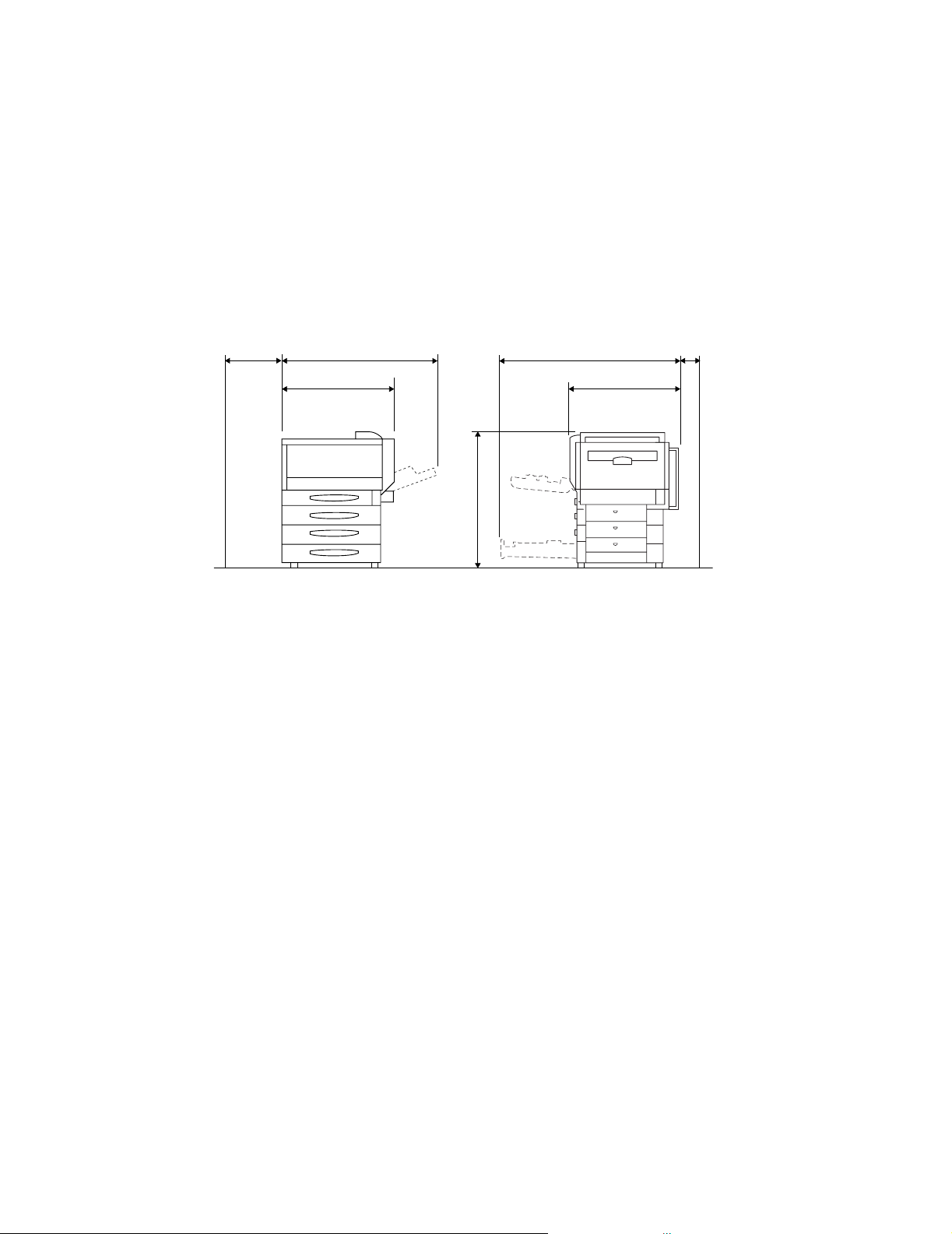
2-4. Space Requirements
• To ensure easy machine operation, replacement of consumables, and maintenance service job, provide the following space for the installation of the machine.
300
694
947
774
1012
100
594
Unit: mm
4134G003AA
29
Page 30

3. PRECAUTIONS FOR USE
3-1. To ensure that the printer is used in an optimum condition
• never place heavy objects on the printer or subject the printer to shocks.
• Insert the power plug all the way into the outlet.
• Never remove secured panels or covers while the unit is printing.
• Never turn off the unit while it is printing.
• Provide good ventilation when using the printer in a confined space for a long period of
time.
• Never use flammable sprays near the printer.
• If the printer becomes exceptionally hot or produces abnormal noise, turn it off and
unplug it.
• Do not turn on the power switch at the same time that you plug the power cord into the
outlet.
• When unplugging the power cord, do not pull on the cord; hold the plug and pull it out.
• Do not bring any magnetized object near the printer.
• Do not place a vase or vessel containing water on the printer.
• Be sure to turn off the power switch at the end of the workday or upon power failure.
• Use care not to drop paper clips, staples, or other small pieces of metal into the printer.
3-2. Operating Environment
The operating environmental requirements of the printer are as follows.
• Temperature: 10-32.5°C
• Humidity: 15-85%
• Rate of temperature change: 10°C/h, 50° F/h
• Rate of humidity change: 20% RH/h
3-3. Power Requirements
The power source voltage requirements are as follows.
• Voltage fluctuations AC 120, 220-240 V ± 10%
• Frequency fluctuations 50-60 Hz ± 3 Hz
3-4. Other Precautions
Use the following precautions when performing service on a printer that uses a laser.
• When servicing parts in the path of the laser beam (near the Print Head or PC drum), be
sure to first unplug the power supply cord for the unit.
• If the service requires that the power cord be left plugged in, observe the following precautions.
1. Remove your watch, rings and any other reflective objects and wear laser protective
goggles.
2. Keep other personnel away from the service area.
3. Do not bring a highly reflective tool into the laser beam path during servicing.
30
Page 31

4. HANDLING CONSUMABLES
Before using any consumables, always read the container label carefully.
• Paper can be easily damaged by dampness. To keep paper that has been removed from
the wrapper as dry as possible until it is loaded to the printer, store in a sealed plastic bag
in a cool, dark place.
• Keep consumables out of the reach of children.
• Do not touch the PC Drum with bare hands.
• The same sized paper is of two kinds, short grain and long grain. Short grain paper
should only be fed through the printer crosswise, long grain paper should only be fed
lengthwise. The packing material will be marked.
• If your hands become soiled with toner, wash them with soap and water.
• Do not throw away any used consumables or used parts, as they should be collected.
• Do not burn, bury, or pour any consumables down the drain.
• Do not store consumables in a place which:
✽ Is hot and humid.
✽ Is subject to direct sunlight.
✽ Has an open flame nearby.
31
Page 32

5. LIST OF NAMES
4
3
2
1
9
5
6
7
4134G004AA
8
1. 2nd Drawer
2. 1st Drawer
3. Front Door
4. Paper Output Tray
5. Right-side Door Release Lever
6. Duplex Unit (optional)
7. Manual Feed Unit (optional)
8. Power Switch
4134G005AA
9. Power Supply Cord Socket
32
Page 33

MECHANICAL/
ELECTRICAL
33
Page 34

34
Page 35

1. CROSS-SECTION VIEW
1
12
1. Print Unit
2. Toner Cartridge
3. Print Head Unit
4. Paper Exit Roller
5. Fuser Unit
6. Duplex Unit (optional)
7. 2nd Image Transfer Roller
8. Synchronizing Roller Unit
2
3
4
5
6
7
8
9
11
10
9. Manual Feed Unit (optional)
10. Multi-Paper Feed Drawer
11. Paper Feed Unit
12. Transfer Belt Unit
4134M001AA
✽ Paper path
The paper feed method is a 2-way system comprised of the Multi-Paper Feed drawer (250
sheets) and the Paper Feed Unit (500 sheets).
Expandable to a 5-way system by installing up to 2 additional units: the optional Manual
Feed Unit and the Paper Feed Unit (500 sheets).
• Paper fed from each Paper Feed Drawer is transported to the Vertical Transport, image
transfer is then performed by the 2nd Image Transfer roller, the image is fused by the
Fuser Unit and fed out face down.
• For 2-sided copying, first the 2nd side is copied and as soon as the paper moves past the
Fuser Unit, the transport path is switched, the paper is turned over and is transported to
the Duplex Unit.
Since a Circulating System is used, the paper is copied on the 1st side and then fed out.
35
Page 36

2. ELECTRICAL PARTS LAYOUT
2-1. Printer
30
23
1
2
21
22
Front
29
28
27
26
25
24
Front
1. Exit Full Detecting Sensor (PC5)
2. Heater Switch Thermistor (TH3)
3. Fusing Pressure Roller Thermistor
(TH2)
4. Heating Roller Thermistor (TH1)
5. Fusing Cooling Fan Motor (M24)
6. Heating Roller Thermostat (TS1)
7. Paper Exit Detecting Sensor (PC4)
8. Fusing Pressure Roller Thermostat
(TS2)
9. Fusing Pressure Roller Heater Lamp
(H3)
10. Heating Roller Heater Lamp 1 (H1)
11. Heating Roller Heater Lamp 2 (H2)
12. Control Panel (UN1)
13. Loop Correction Detecting Sensor
(PC3)
14. OHP Detecting Sensor (PC1)
15. Synchronizing Roller Front Sensor
(PC2)
16. 1st Drawer Paper Empty Detection
Sensor (PC10)
17. Print Head Cooling fan motor (M8)
18. Temperature/Humidity Sensor (PC21)
3
4
5
6
7
8
9
10
11
34
12
35
13
14
15
16
17
18
19
20
4134M101AA
19. 1st Drawer Paper Size/Width Detecting
Sensor (PC11)
20. AIDC Sensor (PC22)
21. Waste Toner Full Detecting Sensor
(PC20)
22. Front Door Open/Close Detecting
Switch(S2)
23. Power Supply Cooling Fan Motor (M6)
24. Front door switch (S1)
25. DC Power Supply (PU1)
26. Controller Board (PWB-Z)
27. Control Board (PWB-A)
28. 1st Drawer Paper Near Empty Detecting Sensor (PC9)
29. 1st Drawer Set Detecting Sensor
(PC7)
30. Print Head Unit
31. Duplex Unit Drive Motor
32. Duplex Door Detecting Sensor (PC6)
33. Duplex Unit Control Board (PWB-A)
34. Manual Feed Motor
35. Manual Feed Detecting Board (PWBY)
36. Manual Feed Detecting Switch(S4)
36
31
32
33
4134M513AA
36
Page 37

Rear
57
56
58
59
60
61
62
63
64
37
38
39
40
41
42
43
55
54
53
52
37. Registration Sensor (PC23)
38. Ozone Fan Motor (M9)
39. Toner Empty Detecting Sensor Bk
(PC16)
40. High Voltage Unit (HV1)
41. 1st Image Transfer Pressure/Retraction Detecting Sensor (PC24)
42. Transfer Belt Unit Detecting Sensor
(PC26)
43. Heater Lamp Control Board (PWB-T)
44. Print Unit Drive Motor Bk (M4)
45. 1st Image Transfer Pressure/Retraction Clutch (CL1)
46. 1st Drawer Paper Size/Length Detecting Board (PWB-PS)
47. Print Unit Drive Motor YMC(M5)
48. High Voltage Unit 2
49. Print Unit Cooling Fan Motor (M12)
50. Paper Feed Drive Motor (M1)
51. High Resistance Board (PWB-R)
44
45
46
48
49
50
51
52. Transport Drive Motor (M2)
53. Right door switch (S3)
54. Right Door Open/Close Detecting Sensor (PC27)
55. Suction Fan Motor (M13)
56. 2nd Image Transfer Pressure/Retraction Detecting Sensor (PC25)
57. Fusing Drive Motor (M3)
58. Drawer Empty Detecting Sensor Y
(PC19)
59. Toner Cartridge Detecting Sensor Y
(PC15)
60. Toner Empty Detecting Sensor M (PC18)
61. Toner Cartridge Detecting Sensor M
(PC14)
62. Toner Empty Detecting Sensor C
(PC17)
63. Toner Cartridge Detecting Sensor C
(PC13)
64. Toner Cartridge Detecting Sensor Bk
(PC12)
47
4134M102AA
37
Page 38

2-2. Controller
Symbol Item Function
CNINF Connector IEEE1284 Parallel Connector
CNVD Connector Connector for the Print Unit
CNLC Connector Connector for the Control Board
CNOP Connector Connector for the Control Panel
CNROM Connector Connector for the Smart Media Card
CNHDD Connector Connector for the Hard Disk
CNLAN Connector Connector for the 10/100 Base-TX Ethernet RJ45
CNUSB2 Connector Connector for the USB
DIMM0 Standard slot 168 pin SDRAM memory
DIMM1 Expansion Slot 168 pin SDRAM Expansion memory
BATT1 Battery Lithium battery for clock
LED1
LED4
SW1 SW CS Save (maintenance) Switch
LSI1 IC
LSI2 IC Correction LSI (Color match correction)
IC1 IC CPU, Controller control
IC9 EEPROM
Light Emitting
Diode (LED)
Light Emitting
Diode (LED)
LAN Link Display LED (Amber)
LAN Speed Display LED (Green)
Drawing LSI (Image data processing, control panel
control, HDD control)
System Data Storage (MAC address, Counter
information etc.)
4134S501AA
38
Page 39

3. OPERATING SEQUENCE
✽ Conditions: plain A4 paper, full color printing
39
C4134S002CA
Page 40

1. IMAGE STABILIZATION CONTROL
• Consistent image output can be achieved by adjusting the developing bias charge and
the laser intensity. In addition, registration correction control is performed to prevent color
shift.
1-1. Image Stabilization Control
• Image Stabilization Control is divided into 2 types, full correction control and simple correction control. Below is an explanation of each type of control.
Control name Purpose
Leak detection
1
control
2 AIDC intensity control
Maximum density
3
control
Color shift correction
4
control
Laser intensity
5
control
6 Gamma curve control
Simple correction
7
control
✽ Full correction control is complete control 1 through 6.
Set the optimum developing bias charge for the space
between the PC Drum and the Developing Roller to prevent
uneven density and leak images.
Adjusts the intensity of the LED light to ensure a constant
output value provided by the AIDC Sensor for a surface of
the Image Transfer Belt, to which no toner sticks, thereby
controlling variations in characteristics caused by time and
contamination.
Adjusts the pulse width ratio of the developing bias to keep
constant the amount of toner sticking to the surface of the
PC Drum for a 100% solid image.
The Registration Sensor detects the amount of color shift in
the main scanning and sub-scanning directions, and adjusts
laser emission timing.
Adjusts the intensity of the laser light to ensure constant line
and gradation reproduction with changes in characteristics
of the PC Drum, developing, and drum charging due to
environmental changes and durability issues.
Makes a gradation correction by producing a pattern on the
Image Transfer Belt, measuring the image density of the
pattern with the AIDC Sensor, and sending the
measurement results to the controller.
1 Complete execution of Control 1 through 6 is time
consuming and consumes more toner. Therefore, simple
correction is executed to reduce the amount of time required
and toner consumed.
In addition, if correction can not be completed by simple
correction, then full correction is executed.
40
Page 41

1-2. Operation Timing
• Full correction control and simple correction control timing is performed as shown below.
Simple Correction Control Timing Full Correction Control Timing
When turning the Power Switch OFF and ON.
When Front Door is opened and closed When a new Toner Cartridge is detected.
When sleep mode is cancelled. When a new Print Unit is detected.
Printing continuous (when not in a constant
environment).
After printing is complete (when not in a
constant environment).
When a substantial shift occurs after
simple correction is executed
When a new Transfer Belt Unit is
detected.
When a leak occurs during simple leak
detection.
41
Page 42

1-3. Image stabilization control flow
42
C4134S022CB
Page 43

1-4. AIDC Sensor
• The AIDC sensor uses a reflective sensor to detect the amount of toner that sticks to the
Image Transfer Belt. Image stabilization is performed based on the value detected.
Photoreceiver
The surface of
the Image Trans-
C4134S003AA
AIDC Sensor
1. The light-emitting diode emits infrared rays illuminating the toner pattern on the Trans-
fer Belt.
2. The photoreceiver detects the intensity of the infrared light reflected from the toner pat-
tern on the Image Transfer Belt.
3. A voltage corresponding to the intensity of the reflected light is sent to the Master Board
(PWB-A).
Amount of Toner Sticking Intensity of Light Reflected Output
Large Small Low
Small Great High
fer Belt
LED
4004M532AA
43
Page 44

1. PRINT HEAD (PH)
1-1. System Configuration
• Four semiconductors are arranged for each color, and scanning is performed by
1polygon motor.
15
16
1
2
3
4
14
5
13 12
11
8
10
8
76
9
4134M002AA
1. Semiconductor laser Bk
2. Semiconductor laser C
3. Semiconductor laser M
4. Semiconductor laser Y
5. Polygon Mirror
6. G1 lens
7. G2 lens
8. G3 lens
9. SOS Lens
10. SOS Sensor
11. Return Mirror
12. Separation Mirror (BK, C, M)
13. SOS Mirror
14. Cylindrical Lens
15. Return Mirror (light source)
16. Synthetic Mirror (BK, C, M)
44
Page 45

1-2. Laser exposure process
Polygon Mirror
Polygon Motor
C
Bk
M
Y
SOS Lens
G1 G2
G3
SOS Mirror
Separation Mirror (Bk)
4134M030AA
Separation Mirror
Return Mirror
4134M029AA
1. Y The Y laser light enters the cylindrical lens via the return mirror (light source) and the
C, M, Bk laser enters the cylindrical lens via the synthetic mirror and the return mirror
(light source).
2. At the cylindrical lens, the sub-scanning direction of each laser light is condensed in the
vicinity of the polygon mirror.
3. Since the angle of incidence for each color of laser light varies, the laser light reflected
by the polygon mirror is reflected in a different angle for each color.
4. The condensing angle of each color of laser light is corrected by the G1 and G2 lenses
and then reaches each return mirror.
5. Y The Y laser beam is condensed on the PC Drum via the return mirror and the G3
lens. The Bk, M and C laser beams are condensed on the PC Drum via the separation
mirror, return mirror and the G3 lens.
45
Page 46

1-3. Laser emission timing
• When Print is ON, after a fixed amount of time, the “ready” signal is detected and the
laser ON signal is output.
• The laser ON signal triggers the firing of each laser beam which is illuminated onto the
SOS board via the reflecting mirror → cylindrical lens → polygon mirror → G1 and G2
lenses → separation mirror → (Bk) SOS mirror and the SOS lens until an SOS signal is
generated.
• This SOS signal unifies the timing in which the laser beams are radiated for each main
scanning line.
• The SOS signal is only generated from the Bk laser beam but for the other colors, the
emission timing is determined with Bk as a basis.
M
Polygon Mirror
C
Bk
Y
SOS sensor
SOS Mirror
Separation mirror
(For Bk)
4134M030AA
46
Page 47

1-4. Laser emission area
(1) FD Direction
• The laser print timing determines the FD print start signal (/HSYNC) that is output from
the control board and the print start position for the width of the paper size.
• The laser emission area is determined by the paper size. However, 5 mm on both sides
of the paper is the void image area.
(2) CD Direction
• The laser print timing determines the CD print start signal (/TOD) that is output from the
control board and the print start position for the length of the paper size.
• The laser emission area is determined by the paper size. However, 5 mm at the leading/
trailing edges is the void image area.
Void width : 5 mm
Void width: 5 mm
47
C4134S021AA
Page 48

1-5. Cooling of Print Head Unit
• The PH cooling fan motor draws air from around the Print Head Unit to the outside to prevent the unit temperature from rising.
PH Cooling Fan Motor
Duct
4134M048AA
48
Page 49

1. PRINT UNIT
1-1. System Configuration
• Each Print Unit is laid out from the left in the order of Bk, C, M, Y.
• Each of the four colors is provided with a separate reproduction process and is configured with a PC Drum, developer, cleaner, PC Drum charge and a toner cartridge.
1
2
5
4
3
1. Toner Cartridge (TC)
2. PC Drum Charge Corona
3. Cleaning Blade
4. PC Drum
5. Developer Roller
6
6. Cyan Print Unit
7. Magenta Print Unit
8. Yellow Print Unit
7
8
C4134S005AA
49
Page 50

1-2. Drive Print Unit
(1) Drive Overall Unit
• The Print Unit Bk and the Image Transfer Belt provide the drive for the Print Unit Drive
Motor Bk that turns the PC Drum and the Image Transfer Belt.
• Print Units C, M, and Y provide the drive for the Print Unit Drive Motor C, M, and Y that
turns the PC Drum.
• In order to eliminate image noise caused by uneven rotation of the PC Drum and Image
Transfer Belt, a mol gear is used to perform drive coupling.
Print Unit
Drive Motor (C, M, and Y)
Print Unit
Drive Gear
Print Unit
Drive Motor (Bk)
(2) Drive in Unit
• The drive in the unit rotates the waste toner transport screw by means of the PC Drum
gear and then rotates the Developing Roller, Supply Roller and Paddle Roller via a Timing Belt.
4134M004AA
Agitating
Timing Belt
Coupling
Paddle Screw
Supply Roller
Developer Roller
PC Drum
Transport Screw
4134M031AA
50
Page 51

1-3. Print Unit Detection
(1) Set detection
• The set detection for each Print Unit detects whether fusing takes place from the
EEPROM board when the power is OFF/ON and the front door is OPENED/CLOSED.
(2) New unit detection
• New unit detection for each Print Unit is performed by the EEPROM board.
Toner Cartridge
Print Unit
4134M021AA
1-4. Toner Cartridge detection
(1) Set detection
• When the toner cartridge is inserted into the print unit, the cartridge pushes up against
the actuator, the set detection sensor is turned ON, and the toner cartridge is detected.
Toner Cartridge Detecting Sensor
Toner Cartridge
(2) New unit detection
• New unit detection is performed by energizing to the fuse in the new cartride, and fusing.
4134M027AA
51
Page 52

1-5. PC Drum
• The photo conductive drum used in this printer is the organic photo conductor (OPC)
type.
✽ The PC Drum is laminated, coated with a carrier generation layer and a charge holding
layer on an aluminum based cylinder.
Handling
If this type of PC Drum is exposed to light for a long period of time, it exhibits light
fatigue which causes changes in sensitivity. Therefore, when removing the PC Drum
from the printer, cover it with a clean dry cloth to protect it from the light. Also, be
careful not to get dirt on the surface of the PC Drum.
Charge Holding
Layer Carrier Genera-
tion Layer
Aluminum
Base
1167M007AA
1139M007AA
• PC Drum Ground
✽ The ground contact for the PC drum is on the inside at the front of the drum and normally
contacts the shaft on the front plate of the print unit. When the print unit is installed into
the printer, the mounting pin on the front plate of the print unit contacts the frame of the
printer. In this way, the electrical potential exposed to the PC drum is transmitted from the
ground plate to the shaft and the mounting pin, and grounded with the frame.
PC Drum
Ground Plate
Shaft
C4134S007AA
52
Page 53

1-6. PC Drum Charging
• The PC Drum Charge Corona employs a comb electrode Scorotron charger system.
• DC(-) corona charge is applied to the comb electrode, which applies a uniform charge to
the surface of the PC Drum via the grid mesh.
• Using a comb electrode ensures that a charge is concentrated on the grid mesh, thus
reducing the amount of ozone produced.
Comb Electrode
Charger
Grid Mesh
Grid Mesh
PC Drum
4134M018AA
Comb Electrode
Charger
PC Drum
4134M019AA
53
Page 54

(1) Charged area Ozone Ventilation
• The ozone generated by the PC Drum charger for each color is taken in by the Ozone
Fan Motor, goes through a duct in the rear and gets absorbed through the Ozone Fan Filter so that only ozone-free air is emitted from the printer.
Ozone Filter DuctOzone Fan Motor
Suction Entrance
Print Unit
4134M020AB
54
Page 55

1-7. Developing Section
(1) Composition
• The Toner Cartridge and Developing Unit are constructed as illustrated below.
Toner Cartridge
11
10
9
1
8
7
2
34
1. Second Regulator Blade
2. PC Drum
3. Charge Neutralizing Seal
4. Developer Roller
5. Supply Roller
6. Paddle Screw
7. Buffer
5
4134M517AA
Print Unit
6
8. First Regulator Blade
9. Agitating Paddle
10. Hopper
11. Toner Cartridge
4134M021AA
55
Page 56

(2) Toner Conveyor
1. The toner drops from the toner cartridge into the hopper inside the Print Unit.
2. The Agitating Paddle mixes the toner while conveying it to the buffer.
3. The toner is then conveyed onto the Developer Roller via the paddle screw and Supply
Roller.
4. The amount of toner on the Developer Roller is regulated by the 1st Regulator Blade.
5. The toner is then negatively charged by the 2nd Regulator Blade.
6. Toner sticks to the electrostatic latent image on the surface of the PC Drum.
7. The remaining toner is discharged via a charge neutralizing seal and conveyed to the
Supply Roller.
Toner Replenishing
Paddle Screw
Supply Roller
Developer Roller
Agitating Paddle
2nd Regulator Blade
4134M051AA
Toner Cartridge
Charge Neutralizing Seal
Developer
Roller
Hopper
Buffer
1st Regulator
Blade
Paddle Screw
Supply Roller
4134M517AA
56
Page 57

(3) Developing System
• Two types of Developing Systems are used, a non-contact developing system and an
alternating current application system.
1. A negative charge is applied to the Supply Roller and toner sticks to the Developer
Roller.
2. The toner is evened out by the 1st Regulator Blade.
3. A negative charge is applied to the 2nd Regulator Blade and the toner is negatively
charged.
4. Since an alternating current is applied to the Developer Roller, if there is negative ele-
ment, the toner sticks to the PC Drum. In addition, the image density is determined by
the time for the negative element.
3
1
6
5
2
4
4134M515AA
1. PC Drum
2. 2nd Regulator Blade
3. 1st Regulator Blade
4. Supply Roller
5. Charge Neutralizing Seal
6. Developer Roller
57
Page 58

(4) Toner Level Detection
Toner level detection is performed by a combination of two methods: toner consumption
prediction control method and mechanical detection method 2.
1. Prediction control method
• The amount of toner consumed is computed by dot count for each color.
2. Mechanical detection method
• The amount of overlap of Disk Plate 1 attached to the Agitating Paddle shaft and Disk
Plate 2 on the gear is detected by a sensor according to the excess toner on the Agitating Paddle.
• When there is a great deal of toner, the load to the Agitating Paddle increases so the
amount of overlap of Disk Plate 1 and 2 increases and the amount of time the sensor is
ON is reduced.
• When there is a small amount of toner, the load to the Agitating Paddle decreases so the
amount of overlap of Disk Plate 1 and 2 decreases and the amount of time the sensor is
ON is increased.
3. Toner Empty Detection
• The toner level is detected by the mechanical detection, the value for the amount of toner
consumed is computed and fed back and toner near-empty or toner-empty is detected.
• When toner near-empty or toner-empty is detected, a message is displayed on the control panel.
A lot of toner. Toner is low.
Disk
Plate 2
Toner Empty
Sensor
Disk Plate 1
4134M023AA
58
Page 59

(5) Toner Cartridge Shutter Open/Close Mechanism
• When the toner cartridge is installed into the print unit, the Open/Close Lever is lowered
and Shutter 1 opens.
Open/Close Lever
4134M026AA
4134M024AA
• When the knob on the toner cartridge is turned to the right, Shutter 2 opens and toner is
conveyed to the Print Unit.
59
4134M026AA
Page 60

1-8. Cleaner
• The Cleaning Blade Method is used to remove the toner left on the PC Drum.
• The residual toner, which has been scraped off by the Cleaning Blade, is conveyed by
the conveying screw and collected in the Waste Toner Box.
Cleaning Blade
PC Drum
Toner Conveying Screw
4134M028AA
60
Page 61

1. IMAGE TRANSFER SECTION
1-1. Construction of Transfer Belt Unit
2
3
4
1
10
1. Drive Roller
2. PC Drum
3. Waste Toner Conveying
Coil
4. Cleaner Receive Roller
5. Driven Roller
9
8
6. 2nd Image Transfer
Roller
7. Transfer Belt
8. Cleaner Braid
9. Tension Roller
10. 1st Image Transfer Roller
5
6
7
4134M500AA
61
Page 62

1-2. Transfer Belt Unit Drive
• The Print Unit Drive Motor Bk allows the drive to rotate the drive roller via the clutch and
gear.
2
4134M032AA
1
4
3
C4134S023AA
1. Print Unit Drive Motor Bk (M4)
2. Drive Gear
3. Drive Roller
4. 1st Image Transfer Pressure/Retraction Clutch (CL1)
1-3. New Transfer Belt Unit Detection
• When a new Transfer Belt Unit is installed, the Shading Plate moves in the direction of
the arrow from the pressure of the 1st Image Transfer Roller and is locked into position.
• The Shading Plate moves only once.
• The Shading Plate blocks the detecting sensor and a new Transfer Belt Unit is detected.
4134M504AA
Transfer Belt Unit Detecting Sensor
(PC26)
Shading Plate
62
Page 63

1-4. Transfer Belt Unit Set Detection
• The set detection of the Transfer Belt Unit is performed by the shading of the 1st Image
Transfer Pressure/Retraction Detecting Sensor.
Pressure Cam
Drive Gear
First Image Transfer Pressure/Retraction Detection Sensor (PC24)
1st Image Transfer
Roller
Shading Plate
Transfer Belt
Drive Roller
4134M045AA
63
Page 64

1-5. Color Shift Detection
• Patterns are produced on the surface of the Transfer Belt and the Registration Sensors
detect any color misalignment on the patterns.
(1) Simple correction
• One pattern is produced in the main scanning and sub-scanning directions on the Transfer Belt.
• The pattern is the value determined by applying the last degree of correction.
Registration Sensor (PC23)
M
C
Bk
Pre-pattern
AIDC Sensor (PC22)
(2) Full correction
• Two patterns are produced in the main scanning and sub-scanning directions on the
Transfer Belt twice.
• The pattern is the value determined by applying the last degree of correction.
Registration Sensor (PC23)
C
Bk
M
Pre-pattern
AIDC Sensor (PC22)
Sub-scanning pattern
Y
Bk
Y
Sub-scanning pattern
Bk
Main scanning simple pattern
Y Bk
M
C
Main scanning pattern
Bk
C
M
M
Y
C
Paper
Paper center
Bk
4134M510AA
Y
4134M509AA
64
Page 65

1-6. Color Shift Correction
• In a tandem engine provided with a separate image reproduction process for each of the
four different colors of toner, incorrect color registration, or color shift, is more likely to
occur due to positional deviations among different Print Head Units. Any misalignment
among different colors is automatically detected and corrected both in the main scanning
and sub-scanning directions to Bk.
• The color shift correction includes a simple correction and a full correction.
Print Head (PH) Unit
Timing in which color shift is corrected
Simple correction Full correction
1. Power Switch is turned ON.
2. After cooling the machine.
3. After returning from sleep mode.
4. When shifting occurs more than the
constant amount.
4134M507AA
1. When toner is supplied and a new unit
is detected for the IU.
2. When a substantial shift takes place
after simple correction is performed.
65
Page 66

2. A light-emitting diode emits infrared rays illuminating the color shift pattern on the
Transfer Belt.
3. The infrared light reflected from the color shift pattern is detected by the photoreceiver.
4. A voltage corresponding to the intensity of the reflected light is output to the Master
Board (PWB-A).
Registration Sensor
(PC23)
Photoreceiver
C4134S003AA
AIDC Sensor (PC22)
Power SourceGNDOutput
LED
Transfer Belt
4004M532AA 1136M068AA
66
Page 67

1-7. First Image Transfer Roller Pressure/Retraction Mechanism
(1) Pressure/Retraction Mechanism
• The rotation of the retraction gear causes the pressure cam to rotate and by raising the
1st Image Transfer Roller, pressure/retraction is applied to the Image Transfer Belt.
• When the 1st Image Transfer pressure/retraction clutch is ON, the rotation of the Print
Unit Drive Motor Bk is relayed to the retraction gear.
• The pressure position is detected by the count of a predetermined period of time after the
1st Image Transfer Pressure/Retraction Detecting Sensor is ON.
• The retracted position is detected by the 1st Image Transfer Pressure/Retraction Detecting Sensor.
Pressure Cam
Retraction
Gear
First Image Transfer Pressure/Retraction Detecting Sensor (PC24)
1st Image Transfer
Roller
Shading Plate
Transfer Belt
Drive Roller
4134M045AA
67
Page 68

(2) Pressure Position Switching Mechanism
• To prolong the durability of the Y, M, and C PC Drums, the pressure position of the Y, M,
C transfer rollers is switched with that of the Bk transfer roller when in the monochrome
mode.
• The switching of the pressure position changes the stop position of the cam based on the
number of motor pulses.
• In monochrome mode, only the 1st Image Transfer Roller for Bk presses against the
Image Transfer Belt.
• In color mode, the 1st Image Transfer rollers for all the colors, Y, M, C, Bk, press against
the Image Transfer Belt.
Cam
Y
4134M035AB
Standby
Mode
Black and White
Mode
Color Mode
Bk
CM
68
Page 69

1-8. 2nd Image Transfer Pressure/Retraction Mechanism
• The 2nd Image Transfer Pressure/Retraction Mechanism is performed by means of rotation of the supply Drive Motor.
• The cam rotates and the pressure lever applies pressure/retraction to the 2nd Image
Transfer Roller.
• The pressure/retraction position is detected by the 2nd Image Transfer Roller Pressure/
Retraction Detecting Sensor.
Cam
Shading Plate
Retracted
2nd Image Transfer Pressure Detection Sensor
(PC25)
Lever
2nd Image
Transfer Roller
Shaft
4134M036AB
Pressed
4134M037AB
69
Page 70

1-9. 2nd Image Transfer
• By applying the 1st Image Transfer bias, the toner image on the PC Drum is transferred
to the Transfer Belt in the order of: Y, M, C, Bk.
PC Drum
To ne r
1st Image Transfer Bias
1st Image Transfer Roller
Transfer Belt
4134M501AB
1-10. 2nd Image Transfer
• By applying the 2nd Image Transfer bias, the toner image on the Transfer Belt is transferred to the paper.
Driven
Cleaner Receive
Roller
2nd Image
Transfer Roller
Transfer Belt
70
2nd Image Transfer
Bias
4134M502AB
Page 71

1-11. Image Transfer ATVC Control
• The resistance value of the Second Image Transfer Roller and the Transfer Belt is measured and its voltage is controlled at the appropriate level.
• The 2nd Image Transfer ATVC adjustment is made when the Power Switch is turned ON
or Front Door is opened and closed.
✽ ATVC: stands for Auto Transfer Voltage Control
• The 2nd Image Transfer ATVC current is output and resistance of the 2nd Image Transfer Roller is measured.
• The 2nd Image Transfer output current is determined according to the measured value,
environment, monochrome/color mode and paper type and width.
ATVC beginning
Cleaning of the 2nd Image Transfer Roller
ATVC current is output to 2nd Image Transfer Roller.
Resistance of the 2nd Image Transfer Roller is measured.
2nd image transfer ATVC current is decided.
High Voltage Unit 2 HV2
ATVC Current
2nd Image Transfer Roller
Transfer Belt
Cleaner Receive Roller
Constant
current
Resistance
measurements
C4134S038AA
Control Board
PWB-A
C4134S039AA
71
Page 72

1-12. Temperature/Humidity Sensor
• The Temperature/Humidity Sensor detects the temperature and humidity inside the
printer and adjusts the second image transfer bias potential.
4134M009AA
Temperature/Humidity
Sensor (PC21)
Temperature data
Humidity
data
4131M029AA
Control Board (PWB-A)
High Pressure Unit 1
(HV1)
2nd Image Transfer
Bias
72
Page 73

1-13. Transfer Belt Cleaning Mechanism
• The Cleaning Blade scrapes any residual toner off the surface of the Transfer Belt.
• The Cleaning Blade uses a fixed blade method in which the blade is in constant contact
with Transfer Belt.
• After the power is turned ON and a predetermined number of copies are printed, the
Transfer Belt is turned backward for a predetermined period of time to remove residual
toner and paper dust wedged between the Cleaning Blade and Transfer Belt.
Cleaning Blade
Cleaner Receive Roller
Transfer Belt
Driven
4134M046AA
1-14. Cleaning the 2nd Image Transfer Roller
• To remove residual toner from the surface of the 2nd Image Transfer Roller, a reverse
bias is output intermittently to the roller.
• The residual toner is moved to the surface of the Transfer Belt, and collected by the
Cleaning Blade.
• Cleaning is initiated when the Power Switch is turned ON or Front Door is opened/closed
or when jam or trouble returns occur.
2nd Image
Transfer Roller
Bias Intercept
Reverse Bias
Bias Contact
Charge
Neutralizing Bias
4134M010AB
73
Page 74

1-15. Waste Toner Box
• The Cleaning Blade scrapes any residual toner off the surface of the Transfer Belt.
• The residual toner, which has been scraped off by the Cleaning Blade, is conveyed by
the conveying screw and collected in the Waste Toner Box.
• The waste toner conveying coil is rotated by the drive transmission of the driven roller.
Waste Toner Conveying
Screw
Transfer Belt
4134M039AB
Waste Toner Box
(1) Installing the Waste Toner Box
• If the Waste Toner Box has not been mounted, the front door will not shut.
(2) Waste Toner Near-Full/Full Detection
• For waste toner near-full/full detection, the amount of overlap of Disk Plate 1 attached to
the agitating paddle shaft and Disk Plate 2 on the drive gear is detected by the Waste
Toner Full Detecting Sensor according to the excess of toner on the agitating paddle
inside the Waste Toner Box.
• When there is a small amount of toner, the load to the agitating paddle decreases so the
amount of overlap of Disk Plates 1 and 2 decreases and the amount of time the sensor is
ON is increased.
• When there is a great deal of toner, the load to the Agitating Paddle increases so the
amount of overlap of Disk Plate 1 and 2 increases and the amount of time the sensor is
ON is reduced.
Agitating Paddle
Waste Toner Full Detecting Sensor (PC20)
4134M040AA
Cover Plate 1 Cover Plate 2
74
4134M047AA
Page 75

1. FUSING SECTION
1-1. Drive of Fuser Unit
• During the image transfer process, the toner is transferred and fused to the paper.
• The Fusing Method is a roll method whereby a heating roller heated by a heater lamp
and fusing pressure roller are pressed and by passing paper between them, the toner
becomes fused to the paper.
• The heating roller is equipped with two heater lamps, which are switched according to
the paper size.
3
4
12
5
4134M005AB
78
3
62
4134M503AB
7
1. Heating Roller Thermostat (TS1)
2. Heating Roller Heater Lamp 2 (H2)
3. Heating Roller
4. Fusing Pressure Roller Heater
Lamp (H3)
5. Fusing Pressure Roller
6. Heating Roller Thermistor (TH1)
10
5
7. Heating Roller Heater Lamp1 (H1)
8. Heater Switching Thermistor (TH3)
9. Fusing Pressure Roller Thermistor (TH2)
10. Fusing Pressure Roller Thermostat (TS2)
9
75
4
Page 76

1-2. Fuser Unit Drive
• The fusing section is driven by a motor.
Fusing Drive Motor
(M3)
Heating Roller
4134M006AC
1-3. Control of Loop Before Fusing
• A loop is formed in front of the fusing roller to maintain the correct paper feed condition
between the 2nd Image Transfer Roller and the fusing roller.
• The speed of the fusing Drive Motor is regulated in 2 stages to ensure that a loop is constantly being formed.
• The Loop Correction Detection Sensor switches the speed of the fusing motor.
Heating
Roller
Paper
Fusing Pressure
Roller
Actuator
Loop Correction Detection
Sensor (PC3)
4134M508AA
Second Image Transfer Roller
76
Page 77

1-4. New Fuser Unit Detection
• New unit detection is perdormed by energizing to the fuse in the new unit, and fusing.
1-5. Pressure of Fusing Roller
• The Fusing Pressure Roller and the Heating Roller are pressed against each other at all
times. They are released for maintenance service or replacement of parts.
• If a paper misfeed occurs in the Fuser Unit, the Fusing Misfeed Clearing Levers are
pulled upward to release pressure between the two rollers.
Fusing Misfeed Clearing Levers
Pressure Spring
4134M007AA
77
Page 78

1-6. Temperature Control
• Heater lamps are turned ON and OFF to keep the surface temperature of the Fusing
Pressure Roller and Heating Roller at predetermined levels.
• The heating roller has two heater lamps with different heat intensity and light distribution,
which are switched according to the paper size.
• The surface temperature of the heating roller and the fusing pressure roller is detected
by a thermistor and the heater lamps are turned ON or OFF.
• If the surface temperatures of the Fusing Pressure Roller and Heating Roller run inordinately high, power to the heater lamps is shut down.
• When an error occurs, with the exception of “No paper”, “Paper misfeed” or “size error”,
the power to the heater lamps is shut down.
(1) Fusing Temperature control flow
• Control is different according to the state of the engine.
Power ON
Emergency Stop Error
Emergency Stop Error
Pre-heat Mode Release
Command Receipt
Emergency Stop Error
Temperature Control at
Warm-up
Temperature Control during
standby
Pre-heat Mode Start Command Receipt
Pre-heat Mode Temperature
Control
Sleep Start Command Receipt
Heater OFF
Error Release/Power-saving Mode Release Command Receipt
Print Completion
Print receipt
Emergency Stop Error
Temperature Control during
Printing
C4134S040AA
78
Page 79

(2) Control at Warm-up
• The temperature is adjusted to the printing temperature and the heating roller and fusing
pressure roller are warmed up.
• Warm-up control has two modes based on the temperature of the heating roller when the
warm-up is started.
Name
Cold start 100 Less than 100°C
Warm start 100 More than 100°C
Control at cold start
Name
Heating
Roller
Fusing
Pressure
Roller
Control at warm start
Name
Heating
Roller
Fusing
Pressure
Roller
Set Temper-
ature
150°C
150°C – 145°C 150°C
Set
Temperature
150°C
150°C –
Temperature of Heating Roller when
initialize starts
Fusing Motor
Start-up
Conditions
More than
120°C
Fusing Motor
Start-up
Conditions
More than
120°C
Warm-up Completion
Conditions
145°C 150°C
Warm-up Completion
Conditions
After the fusing motor
has been driven for
more than 10 seconds
at more than 145°C.
After the fusing motor
has been driven for
more than10seconds
at more than 145°C.
Fusing Motor Stop
Conditions
Fusing Motor Stop
Conditions
After the fusing motor
has been driven for
more than 10 seconds
at more than 150°C.
After the fusing motor
has been driven for
more than10seconds
at more than 150°C.
(3) Temperature Control During Standby
• During standby, after warm-up or when print is complete, the decline in temperature of
the heating roller and the fusing pressure roller is controlled.
Within 30 sec. after warm-up
ends
For Standby modes other than in
the above situations
Heating Roller
temperature
170°C 170°C
170°C 170°C
Fusing Pressure Roller
temperature
79
Page 80

(4) Temperature Control During Printing
• Temperature control is performed for each roller based on the paper size and number of
copies.
Control temperature
(Heating roller/
Heating roller °C)
Paper Size
1st sheet 173/155 180/183 173/155 180/183
2nd through 5th sheets 165/155 170/178 165/155 170/178
6th sheet or beyond 158/155 165/165 158/155 165/165
Control temperature
(Heating roller/
Heating roller °C)
Paper Size –
1st sheet 171/171 173/155 180/165
2nd through 5th sheets 170/170 165/155 170/155
6th sheet or beyond 170/170 158/155 170/155
(5) Pre-heat Mode Control
• The temperature of the heating roller and fusing pressure roller is lowered to reduce the
amount of electricity consumed during standby.
• The temperature is controlled so that the appropriate printing temperature is achieved
within 30 seconds.
• When the pre-heat completion message is received, the printer moves to standby control
mode.
Plain Paper Thick Paper
216 mm or
less
OHP Double sided (plain paper)
More than
216 mm
216 mm or
less
216 mm or
More than
216 mm
less
More than
216 mm
Name Set Temperature
Heating Roller 138°C
Fusing Pressure
Roller
(6) Sleep Mode
• When the sleep mode start command or power saving start mode command given, the
printer goes into this mode.
• Both the heating roller and fusing pressure roller turn OFF to reduce the amount of power
consumed.
• When the sleep mode completion or power saving mode completion commands are
given, the printer goes into warm-up control.
132°C
80
Page 81

(7) Heating heater switch control
• The control begins from Heater 1 when the Power Switch is turned ON.
• This control is continuously performed while the heater is ON.
During
warm-up
Switch to
Heater 2
Switch to
Heater 1
Print mode One-sided Printing
Paper type Plain Paper, Thick Paper
Paper width Less than 216 mm More than 216 mm
Number of
continuous
copies
Switch to
Heater 2
Switch to
Heater 1
Print mode Two-sided Printing
Paper type Plain Paper
Paper width Less than 216 mm More than 216 mm
Number of
continuous
copies
Switch to Heater
2
Switch to Heater
1
Target Control Temperature +15°C
Target Control Temperature-2°C
All sheets 1st sheet After the 2nd sheet
Select only Heater 2
Select only Heater 2
All sheets 1st sheet After the 2nd sheet
Select only Heater 2
Select only Heater 2
Within 30 sec.
after a warm-up cycle
Target Control
Temperature -6°C
Target Control
Temperature -10°C
Target Control
Temperature -6°C
Target Control
Temperature -10°C
Standby
Target Control
Temperature +2°C
Target Control
Temperature-2°C
Target Control
Temperature -10°C
Target Control
Temperature -14°C
Target Control
Temperature -10°C
Target Control
Temperature -14°C
Print mode One-sided Printing
Paper type
Paper width
Continuous
number of copies
Switch to
Heater 2
Switch to
Heater 1
OHP
All sheets
Target Control
Temperature +2°C
Target Control
Temperature -2°C
81
Page 82

1. PAPER TAKE-UP SECTION
1-1. 1st Drawer
• The 1st drawer holds 250 sheets of plain paper/50 sheets of thick paper, governmentstandard postcards and transparencies, or 10 envelopes.
Paper size for 1st Drawer
Length Detecting Board
(PWB-PS)
Trailing Edge Guide Plate
(1) Tray set detection
• The shading plate blocks the detection sensor and the machine then determines that the
drawer has been slid into position.
Shading Plate
Front/Rear Edge
Guide Plate
Paper Take-Up
Roller
4134M008AA
1st Drawer Detection Sensor (PC8)
82
4134M011AA
Page 83

(2) Paper Size Detection
• The paper size is detected by a combination of four length detection switches and a
width detection sensor.
SW1
Sector lever
SW2
SW3
SW4
1st Drawer Paper Length Detection
Board
(PWB-PS)
Trailing Edge Guide Plate
1st Drawer Paper Width
Detection Sensor (PC11)
Actuator
Front/Rear Edge
Guide Plate
Paper size
Postcards ON OFF ON OFF ON
A5C ON OFF ON OFF OFF
B5C OFF ON OFF ON ON
Letter C OFF OFF ON OFF ON
A4C OFF OFF ON OFF OFF
G.Legal L ON OFF OFF OFF OFF
Legal L ON ON ON OFF OFF
B4L ON ON ON OFF ON
Ledger L ON ON ON ON ON
A3L ONONONON OFF
Oversized L OFF ON ON ON OFF
Length Detecting Switch (PWB-PS)
SW1 SW2 SW3 SW4
4004M028AB
4134M050AB
Size Detecting
Sensor (PC11)
83
Page 84

(3) Paper Near-empty Detection
• When the number of sheets of paper still available for use reaches a predetermined
level, the printer determines that it is a paper-near-empty condition.
Predetermined No. of Sheets
(Paper Level)
Near Empty
50±20 sheets (80 g/m
2
paper)
Paper NearEmpty Lever
1st Drawer Paper Near-Empty
Sensor
Empty Detecting Sensor (PC9)
4134M042AB
(4) Paper Empty Detection
• The Paper-empty condition is detected by the Paper Empty Detecting Sensor.
Drawer Paper Empty Sensor
Empty Detecting Sensor (PC10)
Paper Empty Lever
84
4134M043AA
Page 85

(5) Paper Take-Up Mechanism
• The Paper Take-Up Roller drives the Paper Take-Up Drive Motor via a gear.
• A Paper Separator Roller is used to prevent double feed.
Paper Take-Up Drive Motor (M1)
Paper Take-Up
Roller
Separator Roll
4134M012AC
4004M601AA
85
Page 86

1-2. 2nd Drawer
• The 2nd Drawer holds up to 500 sheets of plain paper.
• Up to two optional cassettes can be added.
Front/Rear Edge Guide Plate
Trailing Edge Guide
Plate
Right Side
Door
Paper Lifting Plate
(1) Tray set detection
• When the cassette is slid in, the rib actuates the switch, allowing the machine to determine that the cassette has been slid in position.
Tray Set Switch
(SW D)
4658M001AB
4658M010AA
86
Page 87

(2) Paper Size Detection
When the cassette slides in, the Front/Rear and Trailing Edge Guide Plates actuate the
Paper Size Detection Switch allowing the machine to determine the paper size.
Paper
Size
Ledger L HHHHHHHHHHHL
A3L LHHHHHHHHHHL
B4L HLHHHHHHHHHH
Legal L H H L HHHHHHHHH
Letter C HHHHHHHLHHHL
A4C HHHHHHHH L HH L
JIS B5C HHHHHHHHHH L H
✽ ON: L, OFF: H
Trailing Edge
Guide Plate
Paper Size Detection Switch 1
(SW A)
FD1 FD2 FD3 FD4 FD5 FD6 FD7 FD8 FD9
Paper Size Detection Switch 2
(SW B)
SW A SW B SW C
FD10FD1
Paper Size Detection Switch 3
(SW C)
Front/Rear Edge
Guide Plate
CD1
1
4658M014AB
87
Page 88

(3) Paper Empty Detection
• When the number of sheets of paper still available for use reaches a predetermined
level, the printer determines that there is a paper-near-empty condition.
Predetermined No. of Sheets
(Paper Level)
Near Empty
80 ± 30sheets (80 g/m
2
paper)
Paper Near-Empty Sensor (PC103)
Paper Lifting Plate
4134M049AB
(4) Paper Empty Detection
• The paper empty condition is detected by the Paper Empty Sensor.
Paper Empty Sensor (PC102)
4658M012AA
Paper Lifting Plate
4134M516AA
4658M0505AA
88
Page 89

(5) Paper Take-Up Mechanism
• The Paper Take-Up Roller Motor drives the Paper Take-Up Roller via the Paper Take-Up
Clutch.
Paper Take-up Clutch
(CL101)
Paper Take-Up Roller
Paper Take-up Motor (M101)
(6) Vertical Transport Mechanism
• The Paper Take-Up Motor provides the drive for the Vertical Transport Roller.
Paper Take-Up Motor
(M101)
Separator
Roller
Vertica l
Transport Roller
4658M006AB
4658M005AB
89
Page 90

(7) Edge Guides and Trailing Edge Stop
• The Trailing Edge Stop can be removed and reinstalled to the specified position corresponding to the size of the paper to be loaded.
• The Edge Guides can be slid to the exact size of the paper to be loaded.
Trailing Edge Guide Plate Front/Rear Edge Guide Plate
4658M007AA
4658M008AA
(8) Paper Lifting Plate
• The Paper Lifting Plate is locked into position when it is pressed down. It is unlocked
when the drawer is slid into the unit.
• The Paper Lifting Plate is pushed upward by the Paper Lifting Springs at all times.
Spring
Paper Lifting Plate
4004M009AB
90
Page 91

1-3. Manual Feed Tray (Optional)
• Paper can be fed manually one sheet at a time.
• The Manual Feed Paper Take-Up Drive Motor provides the drive for the Manual Feed
Drive Roller.
(1) Manual Feed Paper Take-Up Mechanism
Manual Feed Paper TakeUp Drive Motor (M101)
Manual Feed Driven Roller
Manual Feed
Paper Take-Up
Sensor
Manual Feed Drive
Roller
(2) Manual feed operation
• When paper is set, the sensor on Manual Feed Detecting Board is turned on.
• The Manual Feed Motor rotates, transports paper 15 mm, and goes into Standby mode.
• Paper is supplied to the main unit from the print request issued by the Controller.
4134M013AB
91
Page 92

1. TRANSPORT SECTION
• The Synchronizing Rollers synchronizes the image transfer function (2nd Image Transfer) with paper transport.
1-1. Synchronizing Roller Drive
• The Synchronizing Roller provides the drive for the Transport Drive Motor.
Transport Drive
Motor
Synchronizing Driven
Roller
Synchronizing Driven
Roller
4134M014AB
1-2. Image Transfer Failure Prevention During High Humidity
• When humidity is high and the paper in the printer gets damp, the charge from the image
transfer charger passes through the paper and the Synchronizing Roller, drops into the
frame ground, and Image Transfer Failure (low density image) occurs.
• A High Resistance Board is placed between the Synchronizing Driven Roller and the
frame ground to prevent the flow of image transfer voltage.
Synchronizing Driven
Roller
High Resistance
Board (PWB-R)
4134M015AA
92
Page 93

1-3. Switch of system speed
• The system speed is switched according to the type of paper.
Paper Type System speed
Plain Paper 90 mm/s
Thick paper, OHP, envelopes, postcards,
labels
45 mm/s
1-4. OHP Detecting
• OHP Detecting is performed by the OHP Detecting Sensor.
• Determines whether the paper type set and the OHP detection result match. It becomes
a media error when they do not match.
• When a media error is detected, printing does not occur and the paper is fed out of the
printer.
OHP detection sensor
detection section
OHP Detection Sensor (PC1): prism portion
4134M016AA
93
Page 94

1. DUPLEX UNIT (OPTIONAL) 1-1. Drive of Duplex Unit
• The paper has a printed image on one side is temporarily fed toward the Exit Tray and,
as soon as the trailing edge of the paper moves past the guide plate in front of the Exit
Roller, the Exit Roller is turned backward so that the paper is fed into the Duplex Unit.
• Drive for the Exit Roller is disconnected from the printer when the Duplex Unit is mounted
on the machine and, instead, it is provided by the Duplex Unit Turnover Motor of the
Duplex Unit.
• The Transport Rollers of the Duplex Unit are driven by the Manual Bypass Paper TakeUp Drive Motor.
• The paper is transported to the printer by the Transport Rollers.
Transport Rollers 1
Duplex Unit Drive
Motor (M10)
Transport
Rollers 2
Transport Rollers 3
4134M017AA
94
Page 95

1-2. Paper Feeding System
(1) Operations in 2-sided printing with a single sheet of paper resident in, and cir-
culated through, the system
1. Paper is taken up and fed in and the image on
page 2 of the original is printed.
2
4657M521AA
2. Paper is first transported to the exit portion and
the paper is then switched back.
2
4657M522AA
2
4657M523AA
3. The 1-sided copy moves through the Duplex Unit
and is directly subject to the second copy cycle
without stopping.
95
Page 96

4. The image on page 1 of the original is printed on
the paper that is taken up from the Duplex Unit.
1 2
4657M524AA
5. The first page is fed out of the printer.
2
1
✽ Steps from (2) to (5) are then repeated.
(2) Operations for 2-sided printing with two sheets of paper resident in the system,
and with a new sheet of paper taken up when a printed page with images
printed on both sides is fed out.
4
4657M525AA
1. The first sheet of paper is taken up and fed in and
the image on page 2 of the original is printed.
2
4657M515AA
96
Page 97

2. The paper is switched back in the paper exit section.
2
4657M516AA
3. At the same time, the 2nd sheet of paper is taken
up and fed in.
4. The image on page 4 of the original is printed on
the 2nd sheet of paper.
4
2
4657M517AA
5. The 1st sheet of paper moves through the Duplex
Unit and is directly subject to the second copy
cycle without stopping.
6. The image on page 1 of the original is printed on
the 1st sheet of paper that is re-fed.
7. The second sheet of paper is switched back and
142
fed into the duplex unit.
8. At the same time, the 3rd sheet of paper is taken
up and fed in.
4330M501AA
9. At the same time, the 1st sheet of paper is fed out
of the machine, the image on page 6 is printed on
2
1
the 3rd sheet of paper.
10. The 2nd sheet of paper stops in the Duplex Unit.
6 4
4330M502AA
97
Page 98

11. The 3rd sheet of paper is switched back in the
paper exit area.
6
2
1
4
4330M503AA
12. At the same time, the 2nd sheet of paper is
directly subject to the second copy cycle.
13. The image on page 3 of the original is printed on
the 2nd sheet of paper.
2
1
364
14. The 3rd sheet of paper is stopped in the Duplex
Unit.
15. At the same time, the 4th sheet of paper is taken
up and fed in.
4330M504AA
16. At the same time, the 2nd sheet of paper is fed
4
3
out of the machine, the image on page 8 is
printed on the 4th sheet of paper.
17. The 3rd sheet of paper stops in the Duplex Unit.
2
1
8
6
4330M505AA
98
Page 99

MAINTENANCE
99
Page 100

100
 Loading...