

Page 1
PARTS MODIFICATION NOTICE
REF NO. : MO021065
DATE : 2002/11/27
MODEL NAME : EP1030/1030F
MODEL CODE : 1160
PMN NO. : 027B
SERVICE & PARTS LOGISTICS DIVISION
PAGE NO. :
1/11
MODEL NAME :
SUBJECT : LAMP HEAT-UP ROLLER VERSION ADDED
KB NO. : - - - - - - - - - -
EP1030/1030F
In EP1030/1030F, the Self Heat-Up Roller has been used in the Fusing Unit. This time, a version of the Lamp
Heat-Up Roller is added for these models.
Here are the exclusive parts and additional service information for the new version.
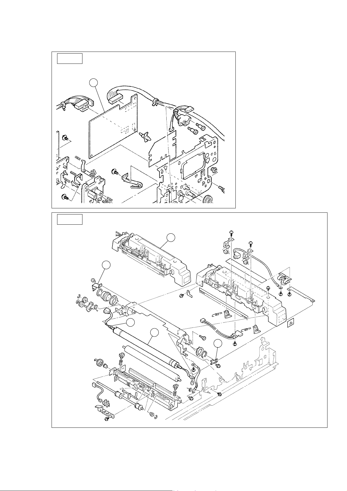
The parts listed below are used only for Lamp Heat-Up Roller version.
1. PW BOARD-A (01)
2. FUSING ROLLER (02)
3. FUSING UNIT (03)
4. HOLDER (04)
5. HOLDER (05)
6. HEATER (06)
The parts listed below are not used in Lamp Heat-Up Roller version.
FIG INDEX PART NO. PART NAME QTY
08 01 1160-0111-03 PWB ASSY 1
12 07 1159-0182-02 HOLDER 1
12 08 1159-6816-01 HARNESS 1
12 26 1159-5757-14 FUSING ROLLER-UPR 1
12 29 1159-0181-02 HOLDER 1
12 36 1159-6811-01 HARNESS 1
12 43 1159-0395-07 FUSING UNIT 1
Accordingly the following SFIX codes have been newly made.
SFIX CODE COUNTRY VOLTAGE FREQUENCY PAPER SIZE
261 NORTH EUROPE 220-240V 50Hz METRIC
262 S. AFRICA/SINGAPORE/
SAUDI ARABIA/MALAYSIA/INDONESIA/
HONG KONG/AUSTRALIA/NEW ZEALAND
271 NORTH EUROPE (WITH SDH) 220-240V 50Hz METRIC
272 S. AFRICA/SINGAPORE/
SAUDI ARABIA/MALAYSIA/INDONESIA/
HONG KONG/AUSTRALIA/NEW ZEALAND
(WITH SDH)
The “I” (Interchangeability) column indicates whether a modified part can be installed in pre-modification machine. If a “Y” is listed under the “I” column, a part under “AFTER MODI. P/NO. ” column can be installed in pre-modification machine and the
machine functions properly. If a “S” is listed, there is a new part which is used with the modified part as a set. The set can be installed in pre-modification machine and the machine functions properly. If a “N” is listed, the modified part cannot be installed
in pre-modification machine. Even though the modified part could be installed in the machine physically, it would not function properly.
The “SE/No. ” column indicates a serial No. and the following 5 meanings. 1. “Blank” shows that there is no modification.( A revised version will be followed as soon as a serial No. is confirmed.) 2. “∗” shows that a modification has been done.( See
the above section for the details.) 3. “N/A” shows that a modification has been done.(The serial No. can not be confirmed.) 4. “AFTER” shows parts which are not used in the production line but used only as the spare parts. 5. “DISCON” shows that
the model has been discontinued for the production.
The “SFIX” column indicates the area codes ( the last three numbers on the item code). The area code “000” means the part can be used in all areas.
220-240V 50Hz METRIC
220-240V 50Hz METRIC
Page 2
REF NO. : MO021065 PAGE NO. : 2/11
FIG.8
01
FIG.12
03
05
06
02
04
Page 3
REF NO. : MO021065 PAGE NO. : 3/11
Se/No.
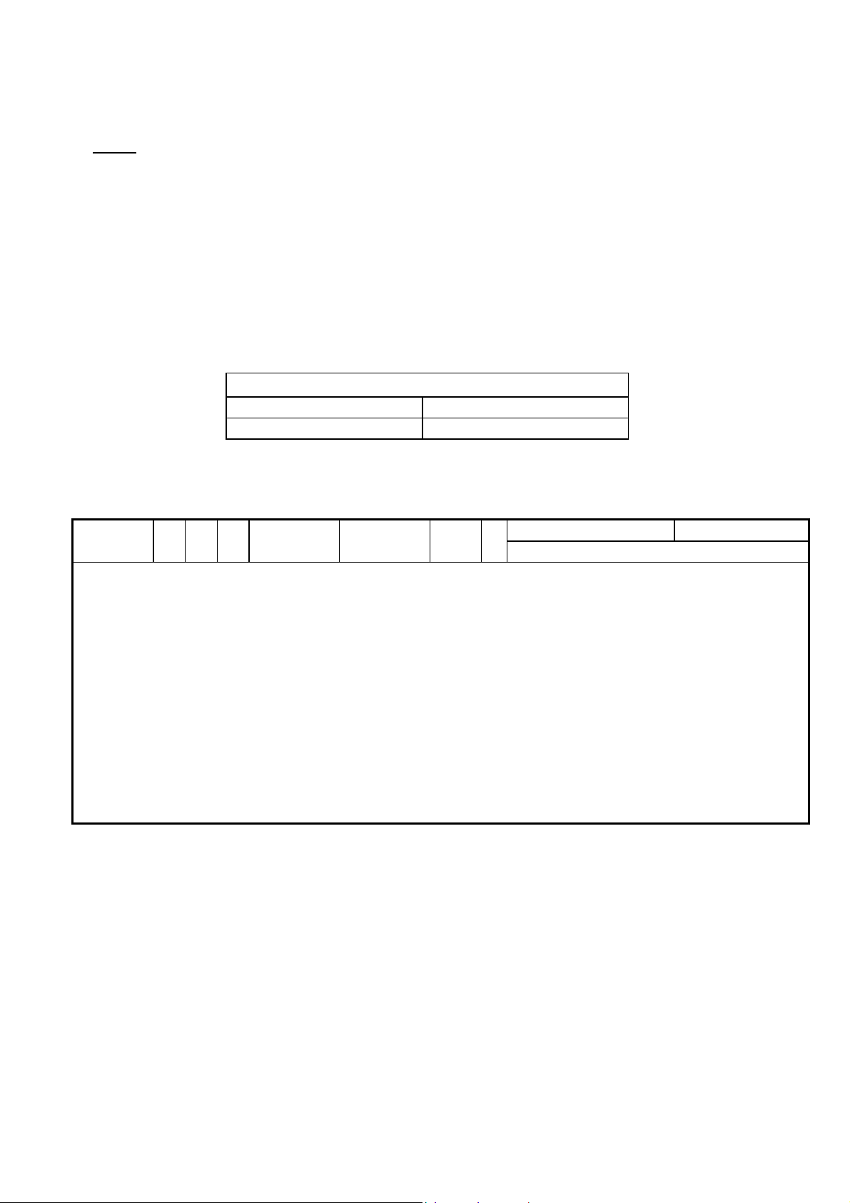
Se/No. is made use of to distinguish between Self Heat-Up Roller version and Lamp Heat-Up Roller version. The
third digit in the Se/No. must be :
Self Heat-Up Roller version : 7 or 8
Lamp Heat-Up Roller version : 9
As they are in separate sequences of Se/No. application, a future PMN will show the effective Se/No. in the
following form.
EFFECTIVE MACHINE Se/No.
∗
Self Heat-Up Roller version Lamp Heat-Up Roller version
MODEL NO. FIG IND BEFORE AFTER QTY I PART NAME SE/NO.
CODE MODI. P/NO. MODI. P/NO. → SFIX
1160 01 08 01 1160-0115-01 1 Y PWB ASSY XX900826
261, 262, 271, 272
1160 02 12 26 1159-5771-01 1 Y FUSING ROLLER XX900826
261, 262, 271, 272
1160 03 12 43 1159-0398-01 1 Y FUSING UNIT XX900826
261, 262, 271, 272
1160 04 12 44 1159-5772-01 1 Y HOLDER XX900826
261, 262, 271, 272
1160 05 12 45 1159-5773-01 1 Y HOLDER XX900826
261, 262, 271, 272
1160 06 12 46 1159-6512-01 1 Y HEATER XX900826
261, 262, 271, 272
Page 4

REF NO. : MO021065 PAGE NO. : 4/11
EP1030/EP1030F
EP1031/EP1031F
SUPPLEMENTARY INFORMATION FOR SERVICE MANUAL
CONTENTS
1. ADDITIONS TO SPECIFICATIONS................................................................................ 5
2. DETAILS OF LAMP HEAT-UP ROLLER SYSTEM SPECIFICATIONS ADDED............ 6
2-1. Fusing Unit............................................................................................................... 6
2-2. Fusing Temperature Control.................................................................................... 6
2-3. Removal of the Fusing Unit.....................................................................................7
2-4. Detection Timings Classified by Malfunction Codes...............................................10
Page 5
REF NO. : MO021065 PAGE NO. : 5/11
1. ADDITIONS TO SPECIFICATIONS
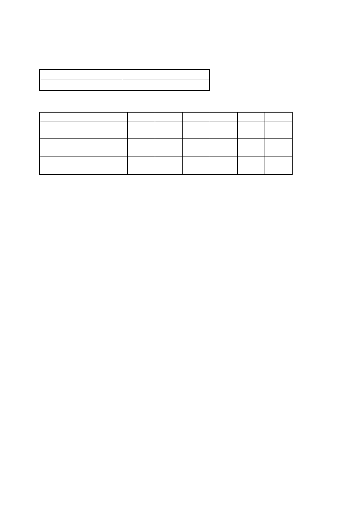
FUSING SYSTEM Heated roller fusing
WARMING-UP TIME 18.0 sec. or less
POWER/CURRENT CONSUMPTION
115V 120V 127V 220V 230V 240V
Exposure Lamp
(Rating)
Fusing Heater
(Rating)
Max. power consumption 870W 920W 980W 910W 960W 1010W
In standby 300W 320W 350W 300W 320W 340W
80V
200W
115V
650W
80V
200W
115V
650W
80V
200W
115V
650W
160V
200W
220V
650W
160V
200W
220V
650W
160V
200W
220V
650W
Page 6
REF NO. : MO021065 PAGE NO. : 6/11
2. DETAILS OF LAMP HEAT-UP ROLLER SYSTEM SPECIFICATIONS ADDED
2-1. Fusing Unit
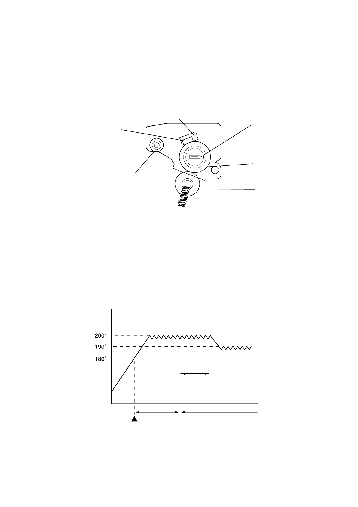
The Lamp Heat-Up Roller system is added to the fusing system. The Upper Fusing Roller heated by the Heater
Lamp and the Lower Fusing Roller are pressed tightly up against each other and paper is fed through the space
between these two rollers so that the toner image is fused in the paper.
3
4
2
5
1
6
7
1. Paper Exit Roller 5. Upper Fusing Roller
2. Fusing Thermister 6. Lower Fusing Roller
3. Fusing Thermoswitch 7. Pressure Spring
4. Fusing Roller Heater Lamp
2-2. Fusing Temperature Control
Warming-up Time = Within 18 sec.
2min.
In Standby
Warming-up Completed
During a Copy Cycle
Page 7
REF NO. : MO021065 PAGE NO. : 7/11
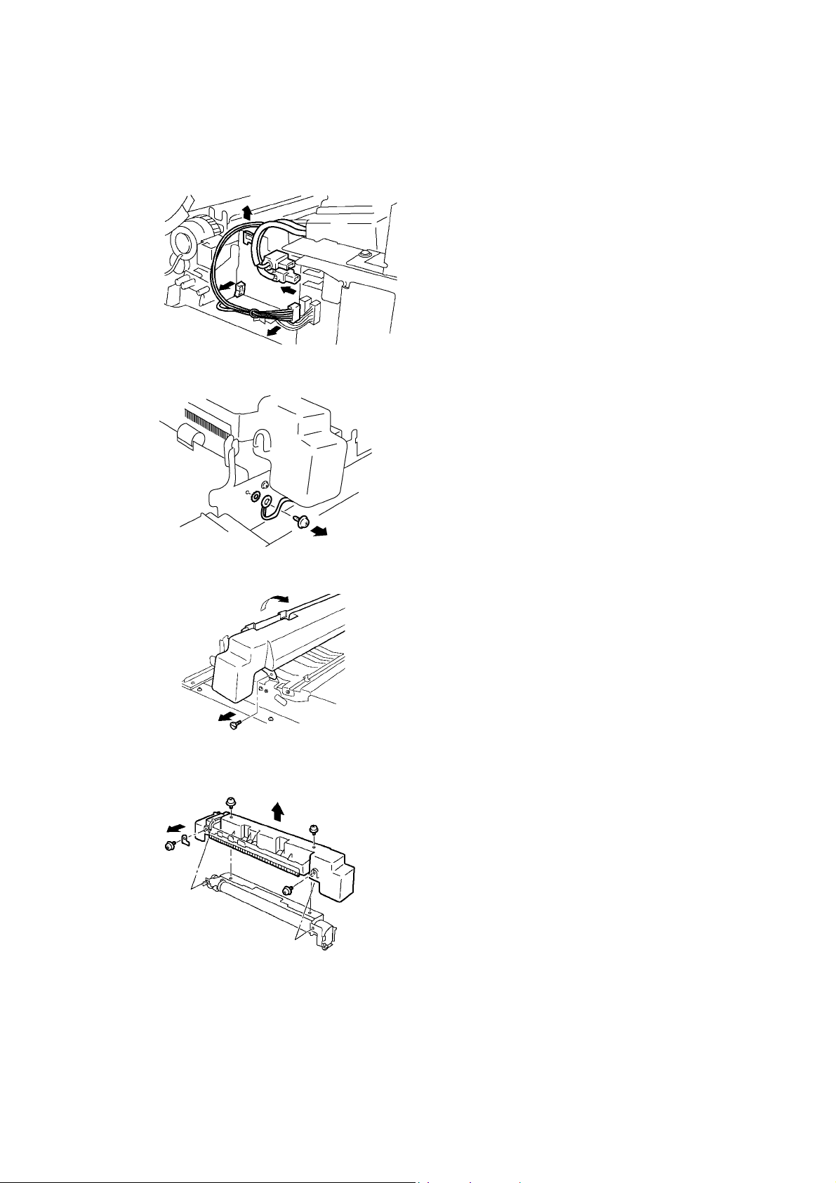
2-3. Removal of the Fusing Unit
1. Swing down the Front Door.
2. Release and swing up the Upper Half of the
copier.
3. Remove the three screws and the Middle
Rear Left Cover.
4. Remove the Harness for the Fusing Unit from
the Edge Cover and remove it from the Cord
Clamp.
5. Remove two terminals for the Fusing Unit.
6. Remove one screw, two washers and
Ground Wire from the Fusing Unit.
7. Remove one Shoulder Screw, turn the
Fusing Unit in the direction of the arrow and
remove it.
8. Remove one screw and the Bracket.
9. Remove the three screws and the Cover for
the Fusing Unit.
Page 8
REF NO. : MO021065 PAGE NO. : 8/11
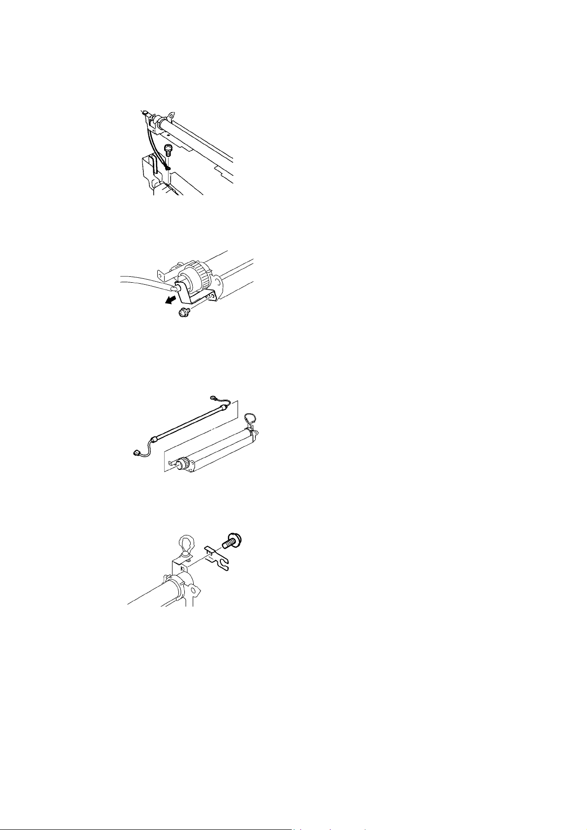
10. Remove one screw and remove the Front
Heater Harness from the Cover.
11. Remove one screw and the Holder.
12. Remove the Fusing Roller Heater Lamp.
13. Remove one screw and the Holder.
Page 9
REF NO. : MO021065 PAGE NO. : 9/11
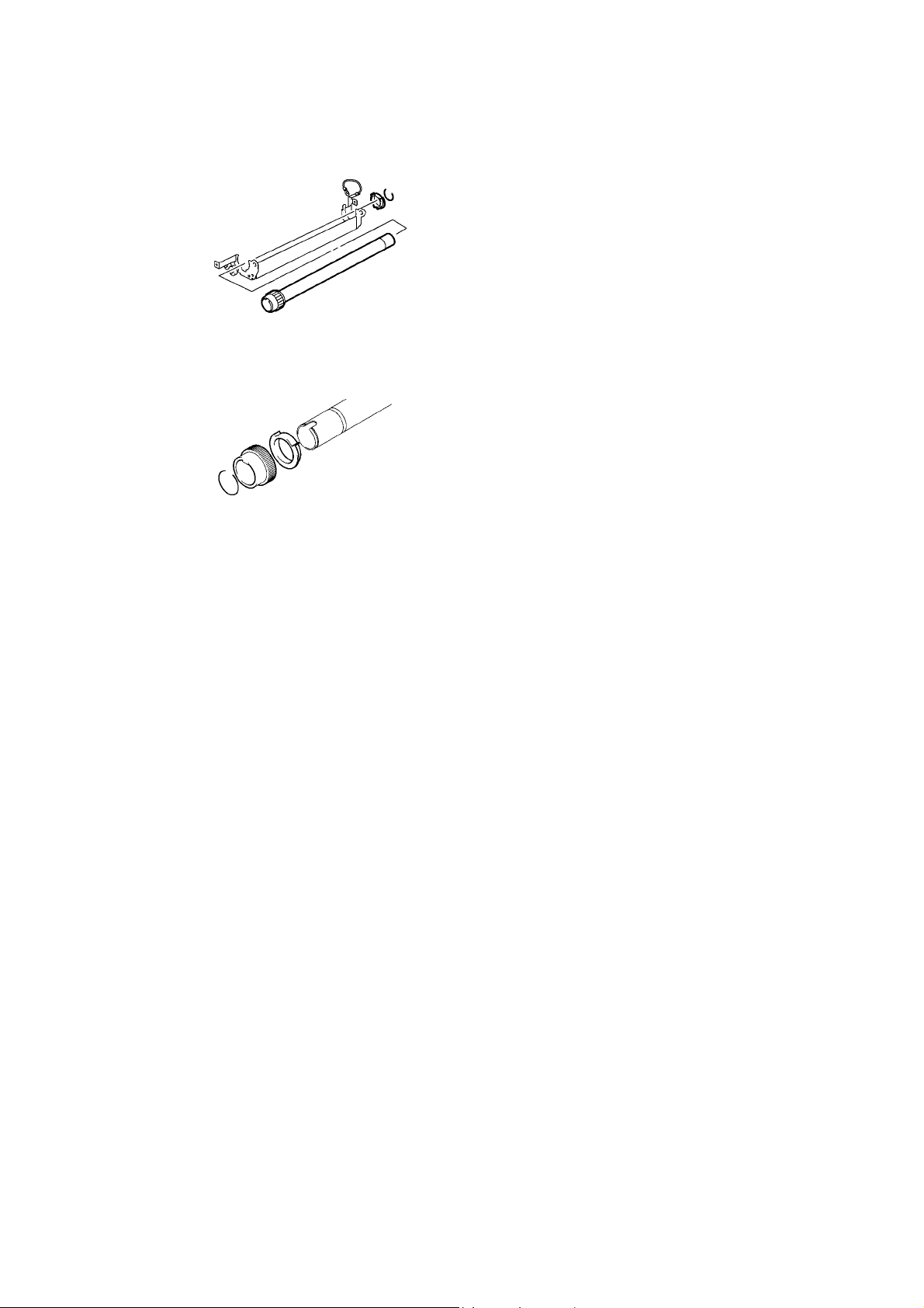
14. Remove one C-clip.
15. Remove the Fusing Roller.
16. Remove one Bushing.
17. Remove one C-clip.
18. Remove the Spur Gear.
19. Remove the Bushing.
Page 10
REF NO. : MO021065 PAGE NO. : 10/11
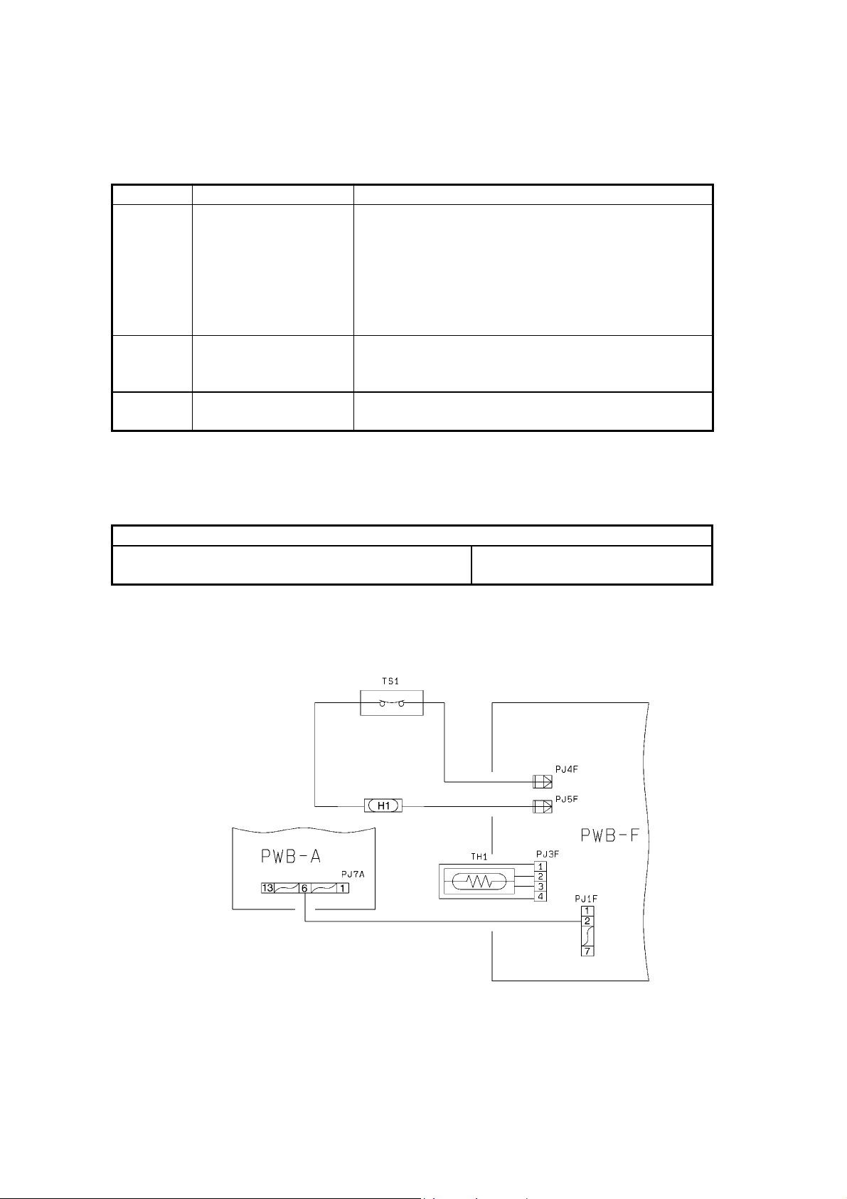
2-4. Detection Timings Classified by Malfunction Codes
Code Description Detection Timing
C50 Warming-up Failure The set temperature is not reached within a given
period of time after the warm-up cycle has been
started.
· 0°C to 60°C: 18 sec.
· 60°C to 120°C: 18 sec.
· 120°C to 160°C: 12 sec.
· 160°C to 180°C: 6 sec.
C51 Abnormally low fusing
temperature
C52 Abnormally high fusing
temperature
(1) C50: Warming-up Failure
C51: Abnormally Low Fusing Temperature
C52: Abnormally High Fusing Temperature
The temperature detected by the Thermistor is less
than 150°C after the warm-up cycle has been
completed.
The temperature detected by the Thermistor is 230°C
or higher after the warm-up cycle has been completed.
·Fusing Roller Heater Lamp (H1)
·Fusing Thermoswitch (TS1)
Relevant Electrical Parts
·AVR
·Master Board (PWB-A)
Page 11
REF NO. : MO021065 PAGE NO. : 11/11
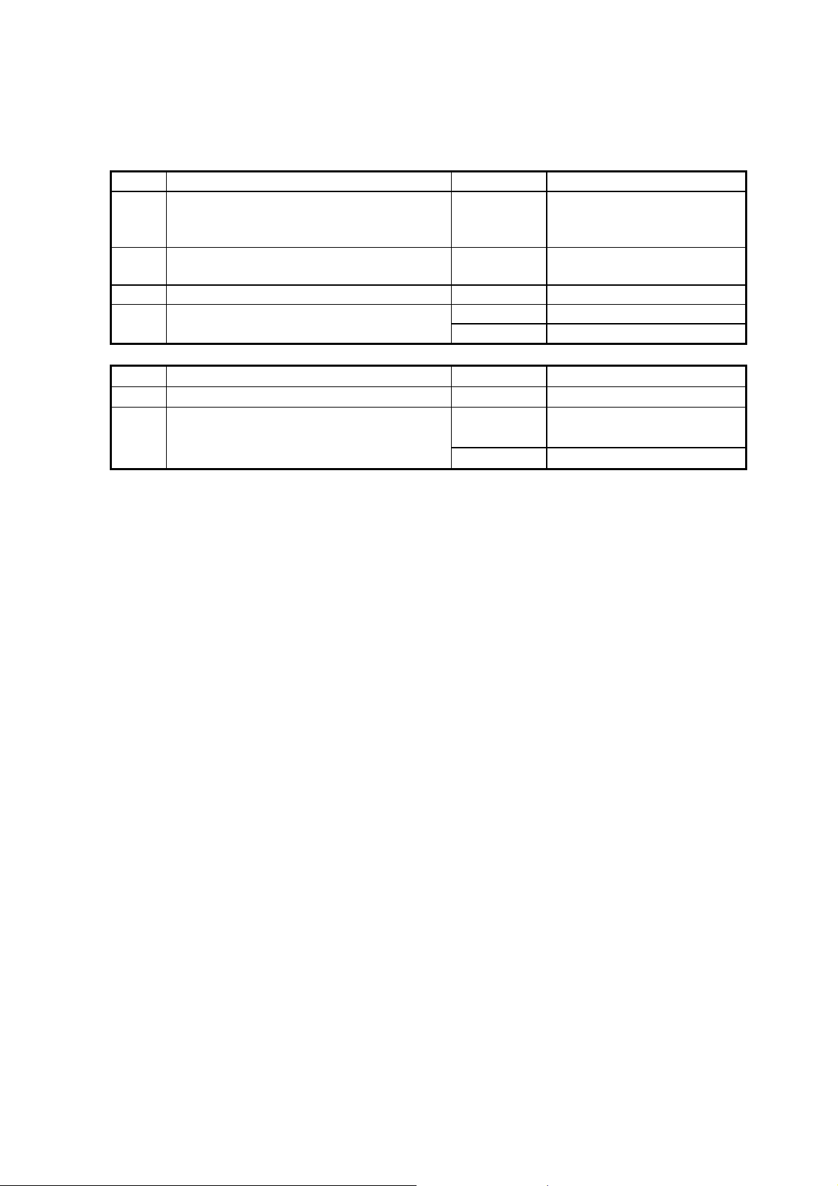
C50, C51
Step Check Item Result Action
1 Is the source voltage being supplied across
NO Change PWB-F.
PJ4F and PJ5F on PWB-F when S1 is
turned ON?
2 Is there continuity across PJ4F and PJ5F
NO Change the Fusing Unit.
on PWB-F as it is checked?
3 Is TH1 installed properly, or dirty? YES Reinstall or clean TH1.
4 Measure the resistance of TH1. Is it infinite? YES Change TH1.
NO Change PWB-F or PWB-A.
C52
Step Check Item Result Action
1 Is TH1 installed properly, or dirty? YES Reinstall or clean TH1.
2 Measure the resistance of TH1. Is it 0Ω or
YES Change TH1.
close to 0?
NO Change PWB-F or PWB-A.
 Loading...