

Page 1

magicolor® 3100 Series
1750051-001B
Service Manual
The essentials of imaging
www.minolta-qms.com
Page 2

ii
Page 3

Introduction
Page 4

Page 5

1. Trademarks
The following are trademarks or registered trademarks of their respective owners. Other product names
mentioned in this manual may also be trademarks or registered trademarks of their respective owners.
Registered trademarks are registered in the United States Patent and Trademark Office; some trademarks
may also be registered in other countries. QMS, magicolor, and the MINOLTA-QMS logo are registered
trademarks of MINOLTA-QMS, Inc. Minolta is a trade-mark of Minolta Co., Ltd.
2. Copyright Notice
This manual is Copyrighted © 2001 by MINOLTA-QMS, Inc., One Magnum Pass, Mobile, AL 36618. All
Rights Reserved. This manual may not be copied in whole or in part, nor transferred to any other media or
language, without the express written permission of MINOLTA-QMS, Inc.
Introduction
v
Page 6

Cautions for operation
1. Marks giving caution
Maintenance operations requiring special cautions or additional information to descriptions of this manual
are presented as "Warning", "Caution", or "Note", according to their nature.
If instructions are not observed, death or serious injury may be caused.
If instructions are not observed, injuries of workers or physical damages to assets
(including this laser printer) may result.
Particularly important essentials for procedures, steps, rules, and others.
Reference Incidental information to descriptions.
2. Related documents
▼ Instruction manuals (standard user manuals)
Describe operation and handling of this laser printer.
▼ Performance specifications
Describe in detail various specifications of this laser printer.
(In the event of discrepancy between this manual and the performance specifications, the performance
specifications shall take preference.)
▼ Spare parts list
Information on maintenance parts (spare parts) for this laser printer
3. Safety
To prevent possible accidents during maintenance operation, you should observe strictly the "Warning" and
"Caution" information in this manual.
Dangerous operations and operations out of range of this manual should be absolutely avoided.
Generally various processes not covered by this manual may be required in actual operation, which should
be performed carefully always giving attention to safety.
3.1 Power source
Keep the power supply off during maintenance operation to prevent electric shock, burns and other
damages. Keep the power plug disconnected during the maintenance operation.
If the power supply should be kept connected for measurement of voltage or other similar reasons,
sufficient care should be given to prevent electric shock, by following the procedures of this manual.
vi
Page 7

Introduction
While the printer is ON, never touch live parts if not required absolutely.
Power is supplied to the power switch / inlet (LVPS ASSY) even while the printer is off.
Never touch its live components.
Do not touch live parts unless otherwise specified.
vii
Page 8

3.2 Driving units
When servicing gears or other driving units, be sure to turn them OFF and plug off. Drive them manually
when required.
Never touch the gears or other driving units while the printer is running.
3.3 High-temperature units
When servicing high-temperature units (securing unit, etc.), be sure to turn them OFF to prevent burns,
injuries and other troubles, remove the power plug and start service processes after they have cooled down
enough.
Immediately after completion of operation, they are still hot. Start services after more
than 40 minutes.
3.4 Laser beams
•If your eyes are exposed to laser beams, you may lose your eyesight.
•Never open the cover if warning label for laser beams is attached there.
•Before disassembling and reassembling this laser printer, be sure to turn it OFF.
•When servicing this laser printer while it is running, be sure to follow the
procedures specified in this manual.
•You should understand the features of the laser beams which are capable of
having an injurious action on the human body, not to extend the danger over the
workers as well as other people around the printer.
Laser beams have features as follows:
•Frequencies are smaller in width than other beams (sun and electric bulbs) and
phases are uniform so that high monochromatic and convergence performance
can be obtained and thin beams of light can reach places at a long distance.
•Due to the high convergence, beams are concentrated in high density and high
temperature, which is dangerous to human body.
Reference: Laser beams of this laser printer is invisible rays which you cannot see.
viii
Page 9

Introduction
3.5 Warning/caution labels
Warning labels and caution labels are attached to this laser printer to prevent accidents Check those labels
for their peeling or stain when servicing the printer.
3.5.1 Caution label for high-temperature units
ix
Page 10

4. List of Abbreviations
ADC Automatic Density Control MPT Multipurpose Tray
AG Analog Ground MSI Multi Sheet Inserter
AUX Auxiliary N/F Normal Force
B/W Blank and White NP No Paper
BCR Bias Charge Roller NVM Non Volatile Memory
BTR Bias Transfer Roller (Image Transfer Roller) OPC Organic Photo Conductor
BUR Back Up Roller P/H Paper Handling
C Cyan PCDC Pixel Count Dispense Control
CART Cartridge PHD Printer Head (Imaging Cartridge)
CCW Counterclockwise Pixel Picture Cell (Picture Element)
CL Clutch PPM Prints per Minute
CLN Cleaning (or Cleaner) PV Print Volume
CLK Clock PWB Printed Wiring Board
CR Charge Roller R/H Right Hand
CRU Customer Replaceable Unit REGI Registration
CRUM CRU Monitor ROS Raster Output Scanner
CW Clockwise RTN Return
DB Developing Bias SEF Short Edge Feed
DTS Detack Saw SG Signal Ground
EP Electrophotography SNR Sensor
FDR Feeder SOL Solenoid
FG Frame Ground SOS Start of Scan
FRU Field Replaceable Unit SPI Scans per Inch
Hex Hexadecimal SYNC Synchronous
I/F Interface T/A Take Away
IDT Intermediate Drum Transfer TC Toner Concentration
ID Image Density (or Identification) TEMP Temperature
KBlackTRTransfer
L/H Left Hand TRANS Transport
L/P Low Paper WDD Wide Range Dynamic Damper
LD Laser Diode XERO Xerographic
LEF Long Edge Feed Y Yellow
M Magenta
x
Page 11

Unpacking the Printer
The printer must be carried horizontally with two or more persons.
Extreme care must be taken to avoid personal injuries
Check visually the printer for evidence of any damages.
Peel all tapes off the printer.
Remove protection parts (2 pieces) from the paper tray.
Introduction
xi
Page 12

xii
Page 13

Contents
Page 14

Page 15

CONTENTS
Introduction ..................................................................................................... iii
1. Trademarks ...................................................................................................................... v
2. Copyright Notice............................................................................................................... v
1. Marks giving caution........................................................................................................ vi
2. Related documents.......................................................................................................... vi
3. Safety .............................................................................................................................. vi
3.1 Power source .........................................................................................................................................vi
3.2 Driving units ......................................................................................................................................... viii
3.3 High-temperature units ........................................................................................................................ viii
3.4 Laser beams ........................................................................................................................................ viii
3.5 Warning/caution labels...........................................................................................................................ix
4. List of Abbreviations......................................................................................................... x
Contents........................................................................................................ 13
Chapter 1 Troubleshooting ........................................................................ 1-23
1. Progressing with the Troubleshooting .........................................................................1-25
1.1 Flow of Troubleshooting.................................................................................................................... 1-25
1.2 Preparatory Requirements................................................................................................................ 1-26
1.3 Cautions for Service Operations ....................................................................................................... 1-27
1.4 Cautions for FIP Use......................................................................................................................... 1-28
2. Level 1 FIP ..................................................................................................................1-30
2.1 Level 1 FIP ........................................................................................................................................ 1-30
2.2 Flow of Level 1 FIP ........................................................................................................................... 1-30
3. Level 2 FIP ..................................................................................................................1-31
3.1 Level 2 FIP ........................................................................................................................................ 1-31
3.2 Error / Status Code List..................................................................................................................... 1-31
3.3 Operating / Clearing the Error........................................................................................................... 1-34
3.4 Error Code FIP .................................................................................................................................. 1-37
3.5 Image Trouble FIP ............................................................................................................................ 1-81
3.6 Roller Circumferences ...................................................................................................................... 1-81
3.7 Other FIPs......................................................................................................................................... 1-92
4. Preventive Maintenance.............................................................................................. 1-94
Chapter 2 Operation of Diagnostics........................................................... 2-95
1. Diagnostics for a Standalone Printer ...........................................................................2-97
1.1 General ............................................................................................................................................. 2-97
1.2 Printing Method ................................................................................................................................. 2-97
Page 16

1.3 Test Print Pattern .............................................................................................................................. 2-98
2. Diagnostics Using the MINOLTA- QMS magicolor 3100 Diagnostics
(Hanabi Service Commander) .........................................................................................2-99
2.1 General ............................................................................................................................................. 2-99
2.2 Preparation ..................................................................................................................................... 2-100
2.3 Operation of magicolor 3100 Diagnostics ....................................................................................... 2-101
2.4 Test Print......................................................................................................................................... 2-103
2.5 Input Test ........................................................................................................................................ 2-104
2.6 Output Test ..................................................................................................................................... 2-107
2.7 Operation of EEPROM.................................................................................................................... 2-110
Chapter 3 Removal and Replacement Procedures ................................. 3-119
1. Removal and Replacement Procedures.................................................................... 3-121
1.1 Before starting service work............................................................................................................ 3-121
1.2 Description of procedures ............................................................................................................... 3-122
RRP1. COVERS............................................................................................................3-123
RRP1.1 CONSOLE PANEL HANABI (PL1.1.1) .................................................................................... 3-123
RRP1.2 COVER ASSY FRONT HEAD (PL1.1.2) ................................................................................. 3-124
RRP1.3 FAN FUSER (PL1.1.7) ............................................................................................................ 3-126
RRP1.4 COVER TOP MAIN (PL1.1.9) .................................................................................................3-128
RRP1.5 COVER ASSY TOP PHD (PL1.1.10) ...................................................................................... 3-129
RRP1.6 COVER REAR (PL1.1.20)....................................................................................................... 3-130
RRP1.7 LINK:L (PL1.1.23).................................................................................................................... 3-131
RRP1.8 LINK:R (PL1.1.23) ................................................................................................................... 3-132
RRP1.9 COVER SIDE R (PL1.1.24)..................................................................................................... 3-133
RRP1.10 COVER ASSY FRONT IN (PL1.1.25) ................................................................................... 3-134
RRP1.11 COVER MSI (PL1.1.26) ........................................................................................................ 3-136
RRP1.12 TRAY ASSY MSI (PL1.1.28) ................................................................................................. 3-137
RRP1.13 COVER ASSY FRONT (PL1.1.29) ........................................................................................ 3-138
RRP1.14 COVER SIDE L (PL1.1.30) ................................................................................................... 3-140
RRP2. PAPER CASSETTE...........................................................................................3-141
RRP2.1 ROLL ASSY (PL2.1.1)............................................................................................................. 3-141
RRP2.2 HOLDER RETARD (PL2.1.3)..................................................................................................3-142
RRP2.3 CASSETTE ASSY FRONT (REFERENCE ONLY) ................................................................. 3-144
RRP3. PAPER FEEDER ...............................................................................................3-146
RRP3.1 CHUTE ASSY TURN (PL3.1.2)............................................................................................... 3-146
RRP3.2 COVER CASSETTE REAR (PL3.1.3)..................................................................................... 3-148
RRP3.3 FEEDER ASSY UNIT (REFERENCE ONLY) ......................................................................... 3-150
RRP3.4 HOUSING ASSY FEEDER L (REFERENCE ONLY) .............................................................. 3-152
RRP3.5 HOUSING ASSY FEEDER R (REFERENCE ONLY) ............................................................. 3-154
RRP3.6 SENSOR HUM TEMP (PL3.2.2) ............................................................................................. 3-156
RRP3.7 HARNESS ASSY OPFREC (PL3.2.3)..................................................................................... 3-157
16
Page 17

Table of Contents
RRP3.8 SWITCH ASSY SIZE (PL3.2.4)...............................................................................................3-158
RRP3.9 LEVER LOW PAPER (PL3.2.7) .............................................................................................. 3-160
RRP3.10 INDICATOR (PL3.2.8) ........................................................................................................... 3-162
RRP3.11 GUIDE INDICATOR (PL3.2.10) ............................................................................................ 3-164
RRP3.12 PICKUP ASSY (PL3.3.1)....................................................................................................... 3-166
RRP3.13 ROLL ASSY FEED (PL3.3.2) ................................................................................................3-168
RRP3.14 SENSOR PHOTO:NO PAPER (PL3.3.3) .............................................................................. 3-170
RRP3.15 SENSOR PHOTO:LOW PAPER (PL3.3.3) ........................................................................... 3-171
RRP3.16 ACTUATOR NO PAPER (PL3.3.4) ....................................................................................... 3-172
RRP3.17 LINK ACTUATOR (PL3.3.5).................................................................................................. 3-173
RRP3.18 SOLENOID FEED (PL3.3.16) ............................................................................................... 3-174
RRP3.19 CLUTCH ASSY TURN (PL3.3.17) ........................................................................................ 3-175
RRP3.20 ROLL ASSY TURN (PL3.3.19).............................................................................................. 3-176
RRP3.21 ROLL ASSY (PL3.3.22)......................................................................................................... 3-177
RRP4. HOUSING ASSY RETARD................................................................................3-178
RRP4.1 HOUSING ASSY RETARD (PL4.1.1) ..................................................................................... 3-178
RRP4.2 ROLL TURN (PL4.1.2) ............................................................................................................ 3-179
RRP4.3 ROLL ASSY RETARD (PL4.1.5) ............................................................................................. 3-180
RRP4.4 CLUTCH TURN (PL4.1.9) ....................................................................................................... 3-182
RRP4.5 STUD RTD (PL4.1.10) ............................................................................................................ 3-183
RRP5. FRONT ASSY IN ...............................................................................................3-184
RRP5.1 FRONT ASSY IN (PL5.1.1) ..................................................................................................... 3-184
RRP5.2 SENSOR ADC ASSY (PL5.1.11) ............................................................................................ 3-187
RRP5.3 SENSOR TNR FULL (PL5.1.13) ............................................................................................. 3-188
RRP5.4 FUSER DRIVE ASSY (PL5.1.18)............................................................................................ 3-190
RRP5.5 LATCH R (PL5.1.21) ............................................................................................................... 3-192
RRP5.6 LATCH L (PL5.1.30) ................................................................................................................ 3-193
RRP6. CHUTE ASSY OUT ........................................................................................... 3-194
RRP6.1 CHUTE ASSY OUT (PL6.1.1) .................................................................................................3-194
RRP6.2 SENSOR PHOTO:FULL STACK (PL6.1.4) ............................................................................. 3-197
RRP6.3 ACTUATOR FULL (PL6.1.5) ................................................................................................... 3-198
RRP6.4 SENSOR PHOTO:DUP (PL6.1.4) ........................................................................................... 3-199
RRP6.5 SENSOR PHOTO:MSI (PL6.1.4) ............................................................................................ 3-200
RRP6.6 ELIMINATOR ASSY (PL6.1.9) ................................................................................................3-201
RRP6.7 ROLL DUP (PL6.1.12)............................................................................................................. 3-202
RRP6.8 ACTUATOR DUP (PL6.1.13) ..................................................................................................3-204
RRP6.9 LATCH OUT (PL6.1.18) .......................................................................................................... 3-206
RRP6.10 ROLL ASSY FEED (PL6.1.27) .............................................................................................. 3-207
RRP6.11 ACTUATOR MSI (PL6.1.37) .................................................................................................3-208
RRP6.12 SOLENOID FEED MSI (PL6.1.40) ........................................................................................ 3-209
RRP6.13 SHAFT ASSY ROLL FEED (REFERENCE ONLY)............................................................... 3-210
RRP6.14 PLATE ASSY BOTTOM MSI (PL6.1.42) ............................................................................... 3-212
RRP7. CHUTE ASSY EXIT...........................................................................................3-213
RRP7.1 CHUTE ASSY EXIT (PL7.1.1)................................................................................................. 3-213
17
Page 18

RRP7.2 ROLL EXIT (PL7.1.4) ............................................................................................................. 3-214
RRP7.3 ROLL MID (PL7.1.5)................................................................................................................ 3-215
RRP7.4 MOTOR ASSY DUP (PL7.1.8) ................................................................................................ 3-216
RRP8. BTR ASSY & FUSER.........................................................................................3-217
RRP8.1 FUSER ASSY (PL8.1.1).......................................................................................................... 3-217
RRP8.2 ROLL ASSY EXIT (PL8.1.3).................................................................................................... 3-218
RRP8.3 ACTUATOR EXIT (PL8.1.7).................................................................................................... 3-220
RRP8.4 BTR UNIT ASSY (PL8.1.12) ................................................................................................... 3-221
RRP8.5 STRAP (PL8.1.13)................................................................................................................... 3-222
RRP9. XEROGRAPHICS..............................................................................................3-224
RRP9.1 ROS ASSY (PL9.1.1) .............................................................................................................. 3-224
RRP9.2 HSG ASSY BIAS (PL9.1.4) ..................................................................................................... 3-226
RRP9.3 CHUTE ASSY REGI (PL9.1.6)................................................................................................3-228
RRP9.4 SENSOR PHOTO:REGI (PL9.1.8).......................................................................................... 3-230
RRP9.5 ACTUATOR REGI (PL9.1.9) ................................................................................................... 3-231
RRP9.6 OHP SENSOR ASSY (PL9.1.12) ............................................................................................ 3-232
RRP10. TCRU ASSY ....................................................................................................3-236
RRP10.1 HOLDER TCRU ASSY UNIT (REFERENCE ONLY) ............................................................ 3-236
RRP10.2 HOLDER TCRU ASSY (1) (PL10.1.1)................................................................................... 3-239
RRP10.3 HOLDER TCRU ASSY (2) (PL10.1.2)................................................................................... 3-240
RRP10.4 HOLDER TCRU ASSY (3) (PL10.1.3)................................................................................... 3-241
RRP10.5 HOLDER TCRU ASSY (4) (PL10.1.4)................................................................................... 3-242
RRP10.6 SWITCH TCRU ASSY (PL10.1.18)....................................................................................... 3-243
RRP10.7 SENSOR TONER LOW (PL10.1.8)....................................................................................... 3-244
RRP10.8 PWBA EEPROM STD (PL10.1.16) ....................................................................................... 3-245
RRP10.9 S-HVPS (PL10.1.17) ............................................................................................................. 3-246
RRP11. FRAME & DRIVE.............................................................................................3-247
RRP11.1 LEVER DRUM:L (PL11.1.4) .................................................................................................. 3-247
RRP11.2 LEVER DRUM:R (PL11.1.4) .................................................................................................3-250
RRP11.3 ACTUATOR I/R (PL11.1.8) ................................................................................................... 3-253
RRP11.4 DEVE DRIVE ASSY (PL11.1.13) .......................................................................................... 3-254
RRP11.5 MAIN DRIVE ASSY (PL11.1.14) ........................................................................................... 3-255
RRP11.6 PWBA ASSY EARTH (PL11.1.16) ........................................................................................ 3-256
RRP12. ELECTRICAL...................................................................................................3-258
RRP12.1 PWBA HNB MCU (PL12.1.1) ................................................................................................ 3-258
RRP12.2 FAN REAR (PL12.1.2) .......................................................................................................... 3-260
RRP12.3 CONTROLLER BOARD (PL12.1.4)(TBD)............................................................................. 3-261
RRP12.4 LVPS (PL12.1.10) ................................................................................................................. 3-262
RRP12.5 HARNESS ASSY AC SW (PL12.1.11) .................................................................................. 3-264
RRP12.6 PWBA HNB DRV (PL12.1.12) ............................................................................................... 3-265
RRP12.7 BOX ASSY MCU/ESS (REFERENCE ONLY) ...................................................................... 3-266
RRP12.8 HOUSING ASSY CONTACT (PL12.1.14) ............................................................................. 3-268
18
Page 19

Table of Contents
Chapter 4 Plug/Jack (P/J) Connector Locations...................................... 4-271
1. Connector [P (plug) / J (jack)]....................................................................................4-273
1.1 List of P/J ........................................................................................................................................ 4-273
1.2 P/J layout diagram .......................................................................................................................... 4-275
Chapter 5 Parts List ................................................................................. 5-279
1. Parts List....................................................................................................................5-281
1.1 Caution for use of parts list ............................................................................................................. 5-281
Chapter 6 Principles of Operation............................................................ 6-313
1. Printing Process ........................................................................................................6-315
1.1 Summary of Printing Process ......................................................................................................... 6-315
1.2 Schematic Diagram for Printing Processes ....................................................................................6-316
1.3 Description of Printing Process Techniques ................................................................................... 6-317
2. Flow of Print Data...................................................................................................... 6-330
2.1 Data Flow........................................................................................................................................ 6-330
3. Drive Transmission Route .........................................................................................6-331
3.1 MAIN DRIVE ASSY ........................................................................................................................ 6-331
3.2 DEVE DRIVE ASSY........................................................................................................................ 6-332
3.3 HOLDER TCRU ASSY (Y, M, C, K)................................................................................................ 6-332
3.4 FUSER DRIVE ASSY ..................................................................................................................... 6-333
3.5 MOTOR ASSY DUP ....................................................................................................................... 6-333
3.6 Gear • Layout .................................................................................................................................. 6-334
4. Paper Transport.........................................................................................................6-335
4.1 Paper Transport Route (without option).......................................................................................... 6-335
4.2 Layout of Paper Transport Route.................................................................................................... 6-336
5. Functions of Major Functional Components ..............................................................6-337
5.1 Paper Cassette ............................................................................................................................... 6-338
5.2 Paper Feeder .................................................................................................................................. 6-340
5.3 Housing Assy Retard ...................................................................................................................... 6-342
5.4 Front Assy In ................................................................................................................................... 6-344
5.5 Chute Assy Out ............................................................................................................................... 6-346
5.6 Chute Assy Exit............................................................................................................................... 6-348
5.7 BTR Assy & Fuser .......................................................................................................................... 6-350
5.8 Xerographics ................................................................................................................................... 6-352
5.9 TCRU Assy ..................................................................................................................................... 6-354
5.10 Frame & Drive ............................................................................................................................... 6-356
5.11 Electrical ....................................................................................................................................... 6-358
6. MODES .....................................................................................................................6-360
6.1 Print Mode....................................................................................................................................... 6-360
19
Page 20

6.2 Operation Modes ............................................................................................................................ 6-360
7. Control.......................................................................................................................6-361
7.1 Control of Paper Size ...................................................................................................................... 6-361
7.2 Selective Control on Paper Pick-up Unit ......................................................................................... 6-361
7.3 ROS Light Quantity Control ............................................................................................................ 6-361
7.4 Process Control .............................................................................................................................. 6-362
7.5 Color Registration Control............................................................................................................... 6-365
7.6 BTR UNIT ASSY Control ................................................................................................................ 6-366
7.7 Toner Control .................................................................................................................................. 6-367
7.8 Fuser Control .................................................................................................................................. 6-368
Chapter 7 Wiring Diagrams and Signal Information................................. 7-369
1. General Wiring Diagram............................................................................................7-371
1. Wiring Diagram between Parts................................................................................. 7-373
1.1 Configuration................................................................................................................................... 7-373
1.2 Notes on Using the Wiring Diagram between Parts........................................................................ 7-375
Chapter 8 Printer Specifications .............................................................. 8-401
1. Configuration of Printer..............................................................................................8-403
1.1 Basic Configuration ......................................................................................................................... 8-403
1.2 Functional Configuration ................................................................................................................. 8-403
2. Electrical Properties...................................................................................................8-404
2.1 Power Source ................................................................................................................................. 8-404
2.2 Power Consumption........................................................................................................................ 8-404
3. Mechanical Properties............................................................................................... 8-404
3.1 Dimensions/Mass of Printer ............................................................................................................ 8-404
3.2 Dimensions/Mass of Universal Paper Tray (standard paper supply - 500 sheets) ......................... 8-405
3.3 Dimensions/Mass of Consumables (CRU) ..................................................................................... 8-405
3.4 Installation Space (min. installation space) ..................................................................................... 8-406
4. Functions...................................................................................................................8-407
4.1 Recording System........................................................................................................................... 8-407
4.2 Exposure System ............................................................................................................................ 8-407
4.3 Development System ...................................................................................................................... 8-407
4.4 Fixing System ................................................................................................................................. 8-407
4.5 Resolution ....................................................................................................................................... 8-407
4.6 Operation Mode .............................................................................................................................. 8-407
4.7 Speed Mode.................................................................................................................................... 8-408
4.8 Print Mode....................................................................................................................................... 8-408
4.9 Paper Mode .................................................................................................................................... 8-408
4.10 Warm-up Time .............................................................................................................................. 8-409
4.11 FPOT (First Print Output Time)..................................................................................................... 8-409
20
Page 21

Table of Contents
4.12 Continuous Printing Speed ........................................................................................................... 8-409
4.13 Printing Area ................................................................................................................................. 8-410
4.14 Input Properties............................................................................................................................. 8-411
4.15 Output Properties.......................................................................................................................... 8-412
4.16 Paper ............................................................................................................................................ 8-412
5. Consumables.............................................................................................................8-413
5.1 Items of Consumables .................................................................................................................... 8-413
5.2 Consumable Life ............................................................................................................................. 8-413
5.3 Parts Requiring Periodical Replacement ........................................................................................ 8-414
6. Operating Environment.............................................................................................. 8-414
6.1 Installation Temperature / Humidity ................................................................................................ 8-414
6.2 Installation Altitude.......................................................................................................................... 8-414
6.3 Installation Horizontality .................................................................................................................. 8-414
6.4 Ambient Lighting ............................................................................................................................. 8-414
7. Safety / Environment Conditions ...............................................................................8-414
7.1 Safety Standard .............................................................................................................................. 8-414
7.2 Laser Safety Standard .................................................................................................................... 8-414
7.3 EMI.................................................................................................................................................. 8-414
7.4 Noise............................................................................................................................................... 8-415
8. Print image Quality .................................................................................................... 8-415
8.1 Image Quality Guarantee Conditions .............................................................................................. 8-415
9. Option........................................................................................................................8-415
9.1 Options to be Installed by Users ..................................................................................................... 8-416
Index ......................................................................................................... I-417
21
Page 22

22
Page 23

Chapter 1 Troubleshooting
Page 24

Page 25
Chapter 1 Troubleshooting
Troubleshooting in this manual assumes use of Diag. tools (maintenance tools).
However, the troubleshooting allows for the case where the Diag tools are not used.
You can correct troubles according to these troubleshooting procedures after
understanding them well.
1. Progressing with the Troubleshooting
After making sure of actual condition of a trouble, proceed with the troubleshooting process making use of
the Fault Isolation Procedure (FIP), “Operation of Diagostics” (Chapter 2), “Plug/Jack (P/J) Connector
Locations” (Chapter 7), and “Principles of Operation” (Chapter 6).
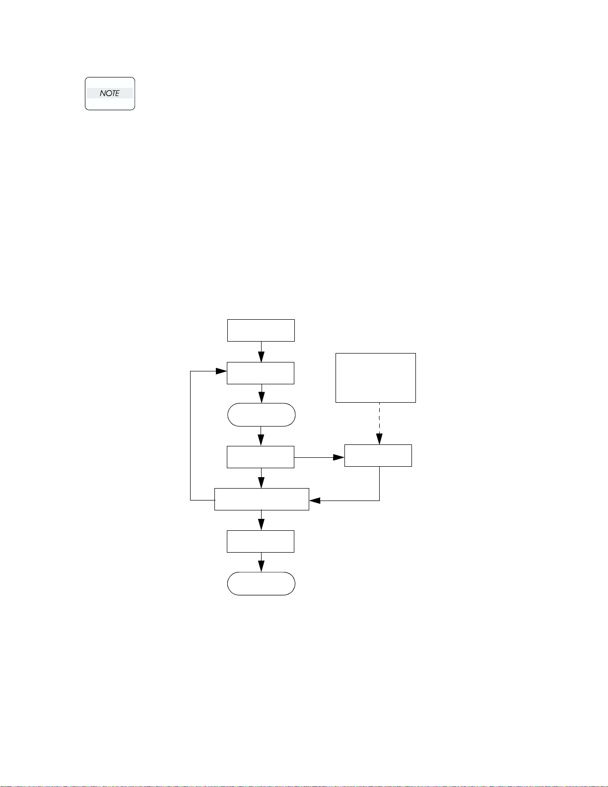
1.1 Flow of Troubleshooting
Flow of the troubleshooting is as follows:
Prior check
Condition check
Start
Level 1 FIP
Trouble recovery check
Preventive
maintenance
End
Diagnostic operation
Operational principle
Wiring connection
diagram
Level 2 FIP
1-25
Page 26

1.2 Preparatory Requirements
Be sure to check the following items before starting any troubleshooting procedures:
1) Voltage of the power supply is within the specifications (measure the voltage at the electric outlet).
2) Power cord is free from breakage, short-circuit, disconnected wire, or incorrect connection in the power
cord.
3) The laser printer is properly grounded.
4) The laser printer is not installed at a place subjected to too high temperature, too high humidity, too low
temperature, too low humidity or rapid change of temperature.
5) The laser printer is not installed close to water service, humidifier, heat generating unit, or fire, in very
dusty place, or a place exposed to air flow from the air conditioning system.
6) The laser printer is not installed in a place where volatile gas or inflammable gas is generated.
7) The laser printer is not installed under direct sunbeams.
8) The laser printer is installed in a well-ventilated place.
9) The laser printer is installed on a stout and stable plane.
10) Paper used meets specifications (standard paper is recommendable).
11) The laser printer is handled properly.
12) Parts which should be periodically replaced are replaced each time when specified number of sheets
have been printed.
1-26
Page 27

Chapter 1 Troubleshooting
1.3 Cautions for Service Operations
1) Be sure to remove the power cord except when it is specifically required.
If the printer is kept ON, never touch the conductive parts while it is not specifically
required.
The power switch/inlet of LVPS is live even while the power supply is cut off. Never
touch the live parts.
2) When checking some parts with covers removed and with the interlock and safety and power switches
ON, remove the connector (P/J151) on the ROS ASSY except when it is specifically required.
When checking some parts with covers removed and with the interlock and safety and
power switches ON, laser beams may be irradiated from the ROS ASSY. Since it is
dangerous, be sure to remove the connector (P/J151) while it is not required.
3) When checking some parts with the left cover removed and power ON, be sure to remove the
connector (P/J5011) on the HVPS while it is not required.
When checking some parts with the left cover removed and power ON, high voltage
may be applied by the HVPS. Be sure to remove the connector (P/J5011) on the HVPS.
When connecting the connector (P/J5011) on the HVPS according to the instructions
of the FIP, never touch the HVPS and parts of high voltage.
4) When using Diag. tools or other tools of high voltage, be sure to keep them covered except when
otherwise specified.
When using Diag.Tool or other tools of high voltage, never touch parts of high voltage.
When using Diag.Tool or other tools of high voltage, be sure to follow the procedure of
this manual.
5)When operating the driving units using the Diag or other tools, be sure to keep them
covered unless otherwise specified.
When operating the driving units using the Diag or other tools, never touch the driving
units. When operating the driving units using Diag or other tools, be sure to observe
the procedures in this manual.
6) When touching hot parts, be careful not to get burnt.
7) Workers should wear a wrist band or the like to remove static electricity from their body, grounding
their body while working.
1-27
Page 28

1.4 Cautions for FIP Use
1) It is assumed in the FIP that the printer controller (CONTROLLER PWB) is normally functioning. If the
trouble cannot be corrected by troubleshooting, replace the printer controller with a normal one and
check for proper operation again.
If the trouble is still not corrected, replace the major parts and then related parts in succession and
confirm according to the procedure of the "Initial check" and "Major check parts".
2) When troubleshooting according to the FIP, normal HNB MCU PWB, Imaging Unit (PHD) or other
parts may be necessary for isolation of failed parts. Prepare them in advance.
3) In the initial check according to the FIP, check only items which can be simply checked.
4) In the initial check according to the FIP, check the constitutive parts of the major check parts and
related parts, as well as major check parts.
5) When working with the printer, Be sure to remove the power cord except when required specifically.
Never touch live parts if not required, while the power cord is connected.
6) Connector condition is denoted as follows:
[P/J12] → Connector (P/J12) is connected.
[P12] → Plug side with the connector (P/J12) removed (except when attached directly to the board).
[J12] → Jack side with the connector (P/J12) removed (except when attached directly to the board).
7) [P/J1-2PIN <=> P/J3-4PIN] in the FIP means measurement with the plus side of the measuring instru-
ment connected to [P/J1] and the minus side to [4PIN] of [P/J3].
8) [P/J<=>P/12] in the FIP means measurement for all terminals corresponding between [P/J1] and [P/J2]
referring to "Wire connecting diagram".
9) In [P/J1-2PIN <=> P/J3-4PIN] in the FIP where voltage is measured, [P/J3-4PIN] on the rear minus
side is always at the AG (analog ground), SG (signal ground), or RTN (return).
Therefore, after checking of proper continuity between AGs, SGs, or RTNs respectively, the rear minus
side can be connected to the PIN of AG, SG or RTN instead of [P/J3-4PIN].
However, care should be taken not to mistake since [AG], [SG], and [RTN] are not on the same level.
10) Measure the voltage of small connectors with the special tool. Handle the tool with care, as the leading
edge of the tool is pointed.
11) When measuring the voltage, set the PDH ASSY, FUSER ASSY, BRT ASSY and paper tray, close the
FRONT COVER ASSY and power ON if not required specifically.
12) Numerical values in the FIP are only for standard. If numerical values are approximate, they should be
considered permissible.
1-28
Page 29

Chapter 1 Troubleshooting
13) Parts which are always removed to check as indicated in the FIP and procedures for that purpose are
not specifically referred to here. They should be handled carefully.
14) "Replacement" in the FIP indicates replacement of parts which are considered to be the source of trou-
ble to be checked after replacing those parts, assemblies containing them, or parts (HIGH ASSY).
15) In the FIP, the paper pick-up unit by means of the paper tray at the lower part of the printer is referred
to as "try 1", the first level of the paper pick-up unit feeder unit as "try 2", and the second level as the
"tray3".
16) In the FIP, existence and non-existence of Diag tools (maintenance tools,) are distinguished in some
cases. Correct troubles according to the instructions in the FIP.
17) In the FIP, procedures are differentiated depending on specifications. Correct troubles according to the
instructions in the FIP.
18) For optional parts, some troubleshooting procedure may follow the manual for those options, of which
you should take note.
Keep those manuals for the optional parts when required.
1-29
Page 30

2. Level 1 FIP
2.1 Level 1 FIP
The level 1 FIP is the first step for trouble diagnosis. The level 1 FIP isolates the presence of various
troubles including error codes, and the level 2 FIP provides a guide for proceeding of the troubleshooting.
2.2 Flow of Level 1 FIP
Ask the operator about trouble status
Is operator’s operating method correct?
Is error code displayed?
Y
Image quality FIP
N
Is trouble related to
image quality?
Y
Y
N
Print in the mode where the trouble
occurred to check if error or jam
occurs
N
Instruct how to operate
1-30
Level 2 FIP
Y
Level 2 FIP Other FIP
N
Page 31

Chapter 1 Troubleshooting
3. Level 2 FIP
3.1 Level 2 FIP
The Level 2 FIP is the trouble diagnostic procedure to sort various troubles in addition to the error codes. In
the troubleshooting, executing the steps given in the FIP or checking procedure allows you to find out a
cause of trouble in a short time.
3.2 Error / Status Code List
This error / status cord list is based on the interface specifications.
Since the error / status codes are represented by the printer controller on the printer,
display on the printer is shown in parentheses below.
Reference FIP
1
2
3
4
5
6
7
8
9
10
11
12
13
Name of error
Contents of error
Yellow Toner Cartridge Detached (Yellow Toner Cartridge Missing)
Cartridge sensor detected no-toner cartridge.
Magenta Toner Cartridge Detached (Magenta Toner Cartridge
Missing)
Cartridge sensor detected no-toner cartridge.
Cyan Toner Cartridge Detached (Cyan Toner Cartridge Missing)
Cartridge sensor detected no-toner cartridge.
Black Toner Cartridge Detached (Black Toner Cartridge Missing)
Cartridge sensor detected no-toner cartridge.
PHD Detached (Imaging Unit Missing)
Machine detected no-Imaging Unit (PHD).
BTR Detached (Transfer Unit Missing)
Machine detected no-Transfer Unit (BTR).
Fuser Detached (Fuser Unit Missing)
Machine detected no-FUSER ASSY.
CRUM ID Error (Call for Service CRUM ID Error)
ID of Imaging Unit (PHD) is different from the recorded ID.
CRUM ID Error (Invalid Imaging Unit)
ID of Imaging Unit (PHD) is different from the recorded ID.
Media Type Mismatch (Media Type Mismatch)
1. Plain paper was detected in the printing by selecting OHP.
2. OHP was detected in the printing by selecting plain paper.
Feed Jam (Media Feed Jam)
Regi sensor cannot detect paper within specified time.
Regi Jam (Media Jam Registration)
Regi sensor cannot detect passage of paper within specified time.
Fuser Jam (Media Jam Fuser)
Exit sensor cannot detect passage of paper within specified time.
Reference
FIP page #
37
38
39
40
41
42
43
44
45
46
47
50
51
1-31
Page 32

Reference FIP
14
15
16
17
18
19
20
21
22
23
24
25
26
27
28
29
Name of error
Contents of error
Duplex Jam (Media Jam Duplex)
Duplex jam sensor cannot detect passage of paper within specified
time.
ROS Failure (Call for Service ROS Motor)
1. Laser power down.
2. SOS signal not detected.
Fuser Failure (Call for Service Fuser Failure)
1. Temperature exceeding 235°C detected consecutively 4 times.
2. Temperature below 120°C detected consecutively 4 times.
3. Resistance value of STS sensor over 2437KW detected
consecutively 4 times.
4. Target temperature is not reached more than 60 seconds after
the fuser lamp lighted up.
5. After the target temperature is reached, the fuser lamp was kept
ON for more than specified time.
6. Value of the STS sensor does not change after the lamp lights up.
7. Temperature exceeding 230°C detected during printing process
consecutively twice.
NV-RAM Error (Call for Service NV-RAM Error)
Error of NV-RAM
ADC Sensor Error (ADC Sensor Dustiness Warning)
Power down of ADC sensor
Fan Motor Failure (Call for Service Fan Motor Error)
Failure of Fan Motor
Low Density Error (Call for Service Low Density)
Toner density is low.
Firmware Error (Call for Service Firmware Error)
Error of software
Environment Sensor Error (Call for Service ENV Sensor Error)
1. The temperature over +100°C or below -20°C was detected.
2. The humidity over 100% was detected.
Yellow Toner Empty (Yellow Toner Low)
Yellow toner emptied.
Magenta Toner Empty (Magenta Toner Low)
Magenta toner emptied.
Cyan Toner Empty (Cyan Toner Low)
Cyan toner emptied.
Black Toner Empty (Black Toner Low)
Black toner emptied.
PHD Life Over (Replace Imaging Unit)
Imaging Unit (PHD) life expired.
BTR Life Over (Replace Transfer Unit)
Transfer Unit (BTR) life expired.
Fuser Life Over (Replace Fuser Unit)
FUSER ASSY life expired.
Reference
FIP page #
52
54
55
56
57
58
60
61
62
63
64
65
66
67
68
69
1-32
Page 33

Chapter 1 Troubleshooting
Reference FIP
30
31
32
33
34
35
36
37
38
39
40
Name of error
Contents of error
ADC Sensor Dustiness (ADC Sensor Dustiness Error)
ADC sensor signal level below specified value.
Front Cover (Front Cover Open)
Front cover open.
BTR Life Warning (Transfer Unit Life Low)
Transfer Unit (BTR) life running out.
Fuser Life Warning (Fuser Life Low)
Fuser life running out.
Paper Empty (Put %s in %s Bin)
Paper in the paper cassette exhausted.
Upper Cassette Detached (Adjust Input Bin)
Paper cassette dislocated.
Full Stack (Output Bin Full)
Delivery tray full of paper
Yellow Toner Empty 2 (Yellow Toner Empty)
Yellow toner emptied.
Magenta Toner Empty 2 (Magenta Toner Empty)
Magenta toner emptied.
Cyan Toner Empty 2 (Cyan Toner Empty)
Cyan toner emptied.
Black Toner Empty 2 (Black Toner Empty)
Black toner emptied.
Reference
FIP page #
70
71
72
73
74
75
76
77
78
79
80
1-33
Page 34

3.3 Operating / Clearing the Error
In the table below, "shutdown" means that control over motors, ROS ASSY, FUSER
ASSY and so on is stopped after a certain time.
In the table below, "print" means that printing is continued even if error message is
generated.
Diag Error Message
(Display Error Mes-
sage)
Yel low To ne r
Cartridge Detached
(Yellow Toner
Cartridge Missing)
Magenta Toner
Cartridge Detached
(Magenta Toner
Cartridge Missing)
Cyan Toner Cartridge
Detached (Cyan
Toner Cartridge
Missing)
Black Toner Cartridge
Detached (Black
Toner Cartridge
Missing)
PHD Detached
(Imaging Unit
Missing)
BTR Detached
(Transfer Unit
Missing)
Fuser Detached
(Fuser Unit Missing)
CRUM ID Error (Call
for Service CRUM ID
Error) or (Invalid
Imaging Unit)
Media Type Mismatch
(Media Type
Mismatch)
Feed Jam (Media
Feed Jam)
Regi Jam (Media Jam
Registration)
Fuser Jam (Media
Jam Fuser)
Operation
Method of clearing
Shutdown
Toner cartridge replacement
Shutdown
Toner cartridge replacement
Shutdown
Toner cartridge replacement
Shutdown
Toner cartridge replacement
Shutdown
Imaging Unit (PHD) replacement
Shutdown
Transfer Unit (BTR) replacement
Shutdown
Power OFF/ON after replacing the FUSER ASSY
Shutdown
Imaging Unit (PHD) replacement
Shutdown
Power OFF/ON after removing the jam paper
Next paper is not picked up after a sheet of paper is delivered during operation
Open and close the front cover after removing the jammed paper
Shutdown
Open and close the front cover after removing the jammed paper
Shutdown
Open and close the front cover after removing the jammed paper
1-34
Page 35

Chapter 1 Troubleshooting
Diag Error Message
(Display Error Mes-
sage)
Duplex Jam (Media
Jam Duplex)
ROS Failure (Call for
Service ROS Motor)
Fuser Failure (Call for
Service Fuser Failure)
NV-RAM Error (Call
for Service NV-RAM
Error)
ADC Sensor Error
(ADC Sensor
Dustiness Warning)
Fan Motor Failure
(Call for Service Fan
Motor Error)
Low Density Error
(Call for Service Low
Density)
Firmware Error (Call
for Service)
Environment Sensor
Error (Call for Service
Sensor Error)
Yellow Toner Empty
(Yellow Toner Low)
Magenta Toner Empty
(Magenta Toner Low)
Cyan Toner Empty
(Cyan Toner Low)
Black Toner Empty
(Black Toner Low)
PHD Life Over
(Replace Imaging
Unit)
BTR Life Over
(Replace Transfer
Unit)
Fuser Life Over
(Replace Fuser Unit)
ADC Sensor
Dustiness (ADC
Warning)
Front Cover (Front
Cover Open)
Operation
Method of clearing
Shutdown
Open and close the front cover after removing the jammed paper
Shutdown
Power ON/OFF
Shutdown
Power ON/OFF
Shutdown
Power ON/OFF
Shutdown
Power ON/OFF
Shutdown
Power ON/OFF
Shutdown
Power ON/OFF
Shutdown
Power ON/OFF
Shutdown
Power ON/OFF
Shutdown
Toner cartridge replacement
Shutdown
Toner cartridge replacement
Shutdown
Toner cartridge replacement
Shutdown
Toner cartridge replacement
Shutdown
Imaging Unit (PHD) replacement
Shutdown
Transfer Unit (BTR) replacement
Shutdown
Clearing the counter after replacing the FUSER ASSY
Print
Open and close the front cover after cleaning the sensor
Shutdown
Close the front cover
1-35
Page 36

Diag Error Message
(Display Error Mes-
sage)
Yellow Toner Near
Empty (Yellow Toner
Low)
Magenta Toner Near
Empty (Magenta
Ton er Lo w)
Cyan Toner Near
Empty (Cyan Toner
Low)
Black Toner Near
Empty (Black Toner
Low)
PHD Life Warning
(Imaging Unit Life
Low)
BTR Life Warning
(Transfer Unit Life
Low)
Fuser Life Warning
(Fuser Life Low)
ADC Sensor
Dustiness (ADC
Sensor Dustiness
Error)
Paper Empty (Put
Paper in Input Bin)
Upper Cassette
Detached (Adjust
Input Bin)
Full Stack (Output Bin
Full)
Yellow Toner Empty 2
(Yellow Toner Empty)
Magenta Toner Empty
2 (Magenta Toner
Empty)
Cyan Toner Empty 2
(Cyan Toner Empty)
Black Toner Empty 2
(Black Toner Empty)
Operation
Method of clearing
Print
Toner cartridge replacement
Print
Toner cartridge replacement
Print
Toner cartridge replacement
Print
Toner cartridge replacement
Print
Imaging Unit (PHD) replacement
Print
Transfer Unit (BTR) replacement
Print
Replace the FUSER ASSY and clear the counter
Print
Clean the sensor and open and close the front cover
Print (Paper cannot be delivered from the cassette)
Replenish the paper
Print (Paper cannot be delivered from the cassette)
Paper cassette replacement
Print
Take out paper from the delivery tray
Shutdown
Toner cartridge replacement
Shutdown
Toner cartridge replacement
Shutdown
Toner cartridge replacement
Shutdown
Toner cartridge replacement
1-36
Page 37

Chapter 1 Troubleshooting
3.4 Error Code FIP
FIP-1 Yellow Toner Cartridge Detached (Yellow Toner Cartridge Missing)
Step Check
Initial check.
Check the following for damage:
Cartridge condition
1
2
3
4
5
6
7
8
9
SW TCRU ASSY (Y) condition
SW TCRU ASSY (Y) actuator condition
SW TCRU ASSY SW TCRU ASSY (Y) connector
condition
Check SW TCRU ASSY
Using the diagnostic tool, check by Diagnostic Input Test.
Does SW TCRU ASSY (Yellow Cartridge Toner Bottle
Sensor) function normally?
Check PWBA HNB DRV for signal
Is P/J51-11PIN <=> P/J51-12PIN 0VDC?
Check SW TCRU ASSY (Y) for signal
Is P/J431-2PIN<=>P/J431-1PIN 0VDC?
Check SW TCRU ASSY (Y) for continuity
Is P431-2PIN <=> P431-1PIN of SW TCRU ASSY (Y)
check continuous?
Check HARNESS ASSY TNR for continuity
J51 <=> J431 check continuous?
Check PWBA HNB DRV for signal
Is P/J42-4PIN<=>P/J42-14PIN 0VDC?
Check PWBA HNB MCU for signal
Is P/J12-27PIN <=> P/J12-17PIN of PWBA HNB MCU PWB
0VDC?
Check HARNESS ASSY DRV2 for continuity
J12 <=> J42 check continuous?
Yes No
With tool
Replace the parts
concerned
Replace PWBA
HNB MCU
Go to step [7] Go to step [4]
Go to step [6] Go to step [5]
Go to step [6]
Go to step [7]
Go to step [8]
Replace PWBA
HNB MCU
Replace PWBA
HNB MCU
Go to step [2]
Without tool
Go to step [3]
Go to step [3]
Replace SW
TCRU ASSY (Y)
Replace
HARNESS ASSY
TNR
Replace PWB
HNB DRV
Go to step [9]
Replace
HARNESS ASSY
DRV2
1-37
Page 38

FIP-2 Magenta Toner Cartridge Detached (Magenta Toner Cartridge Missing)
Step Check
Initial check
Check the following for damage.
Cartridge condition
1
2
3
4
5
6
7
8
9
SW TCRU ASSY (M) condition
SW TCRU ASSY (M) actuator condition
SW TCRU ASSY SW TCRU ASSY (M) connector
condition
Check SW TCRU ASSY
Using the diagnostic tool, check by Diagnostic Input Test.
Does SW TCRU ASSY (Magenta Cartridge Toner Bottle
Sensor) function normally?
Check PWBA HNB DRV for signal
Is P/J51-13PIN <=> P/J51-14PIN 0VDC?
Check SW TCRU ASSY(M) for signal
Is P/J432-2PIN <=> P/J432-1PIN 0VDC?
Check SW TCRU ASSY (M) for continuity
P432-2PIN <=> P432-1PIN of SW TCRU ASSY (M) check
continuous?
Check HARNESS ASSY TNR for continuity
J51 <=> J432 check continuous?
Check PWBA HNB DRV for signal
Is P/J42-5PIN <=> P/J42-14PIN 0VDC?
Check PWBA HNB MCU for signal
Is P/J11-26PIN <=> P/J11-17PIN of HNB MCU WITHMCU
PWB 0VDC?
Check HARNESS ASSY DRV2 for continuity
J12 <=> J42 check continuous?
Yes No
With tool
Replace the parts
concerned
Replace PWBA
HNB MCU
Go to step [7] Go to step [4]
Go to step [6] Go to step [5]
Go to step [6]
Go to step [7]
Go to step [8]
Replace PWBA
HNB MCU
Replace PWBA
HNB MCU
Go to step [2]
Without tool
Go to step [3]
Go to step [3]
Replace SW
TCRU ASSY (M)
Replace
HARNESS ASSY
TNR
Replace PWB
HNB DRV
Go to step [9]
Replace
HARNESS ASSY
DRV2
1-38
Page 39

FIP-3 Cyan Toner Cartridge Detached (Cyan Toner Cartridge Missing)
Chapter 1 Troubleshooting
Step Check
Initial check
Check the following for damage.
Cartridge condition
1
2
3
4
5
6
7
8
9
SW TCRU ASSY (C) condition
SW TCRU ASSY (C) actuator condition
SW TCRU ASSY SW TCRU ASSY (C) connector
condition
Check SW TCRU ASSY
Using the diagnostic tool, check by Diagnostic Input Test.
Does SW TCRU ASSY (Cyan Cartridge Toner Bottle
Sensor) function normally?
Check PWBA HNB DRV for signal
Is P/J51-29PIN <=> P/J51-30PIN 0VDC?
Check SW TCRU ASSY (C) for signal
Is P/J433-2PIN <=> P/J433-1PIN 0VDC?
Check SW TCRU ASSY (C) for continuity
P433-2PIN <=> P433-1PIN of SW TCRU ASSY (C) check
continuous?
Check HARNESS ASSY TNR for continuity
J51 <=> J433 check continuous?
Check PWBA HNB DRV for signal
Is P/J42-6PIN <=> P/J42-14PIN 0VDC?
Check PWBA HNB MCU for signal
Is P/J12-25PIN <=> P/J12-17PIN of PWBA HNB MCU PWB
0VDC?
Check HARNESS ASSY DRV2 for continuity
J12 <=> J42 check continuous?
Yes No
With tool
Replace the parts
concerned
Replace PWBA
HNB MCU
Go to step [7] Go to step [4]
Go to step [6] Go to step [5]
Go to step [6]
Go to step [7]
Go to step [8]
Replace PWBA
HNB MCU
Replace PWBA
HNB MCU
Go to step [2]
Without tool
Go to step [3]
Go to step [3]
Replace SW
TCRU ASSY (C)
Replace
HARNESS ASSY
TNR
Replace PWB
HNB DRV
Go to step [9]
Replace
HARNESS ASSY
DRV2
1-39
Page 40

FIP-4 Black Toner Cartridge Detached (Black Toner Cartridge Missing)
Step Check
Initial check
Check the following for damage.
Cartridge condition
1
2
3
4
5
6
7
8
9
SW TCRU ASSY (K) condition
SW TCRU ASSY (K) actuator condition
SW TCRU ASSY SW TCRU ASSY (K) connector
condition
Check SW TCRU ASSY
Using the diagnostic tool, check by Diagnostic Input Test.
Does SW TCRU ASSY (Black Cartridge Toner Bottle
Sensor) function normally?
Check PWBA HNB DRV for signal
Is P/J51-31PIN<=>P/J51-32PIN 0VDC?
Check SW TCRU ASSY (K) for signal
Is P/J434-2PIN<=>P/J434-1PIN 0VDC?
Check SW TCRU ASSY (K) for continuity
P434-2PIN <=> P434-1PIN of SW TCRU ASSY (K)
check continuous?
Check HARNESS ASSY TNR for continuity
J51 <=> J434 check continuous?
Check PWBA HNB DRV for signal
Is P/J42-3PIN <=> P/J42-14PIN 0VDC?
Check PWBA HNB MCU for signal
Is P/J12-28PIN <=> P/J12-17PIN of PWBA HNB MCU PWB
0VDC?
Check HARNESS ASSY DRV2 for continuity
J12 <=> J42 check continuous?
Yes No
With tool
Replace the parts
concerned
Replace PWBA
HNB MCU
Go to step [7] Go to step [4]
Go to step [6] Go to step [5]
Go to step [6]
Go to step [7]
Go to step [8]
Replace PWBA
HNB MCU
Replace PWBA
HNB MCU
Go to step [2]
Without tool
Go to step [3]
Go to step [3]
Replace SW
TCRU ASSY (K)
Replace
HARNESS ASSY
TNR
Replace PWB
HNB DRV
Go to step [9]
Replace
HARNESS ASSY
DRV2
1-40
Page 41

FIP-5 PHD Detached (Imaging Unit Missing)
Chapter 1 Troubleshooting
Step Check
Initial check
Check the following for damage.
1
2
3
4
5
Imaging Unit (PHD) condition
PWBA CRUM in Imaging Unit (PHD) condition
Check PWBA CRUM
Is PWBA CRUM connector connected to the
harness connector normally?
Check HARNESS ASSY CRUM for continuity
J170 <=> J71 check continuous?
Check HARNESS ASSY EEPROM for continuity
J17 <=> J140 check continuous?
Check Imaging Unit (PHD)
Replace Imaging Unit (PHD), and check if an error occurs
Yes No
Replace the parts
concerned
Go to step [3]
Go to step [4]
Go to step [5]
Replace PWBA
HNB MCU
Go to step [2]
Replace
HARNESS ASSY
CRUM
Replace
HARNESS ASSY
CRUM
Replace
HARNESS ASSY
EEPROM
End of work
1-41
Page 42

FIP-6 BTR Detached (Transfer Unit Missing)
Step Check
Initial check
Check the following for evidence of fault.
1
2
3
4
5
6
Transfer Unit (BTR) condition
SENSOR ADC ASSY condition
Check HARNESS ASSY ADC for connection
Is HARNESS ASSY ADC connected to the SENSOR ADC
ASSY normally?
Check HARNESS ASSY ADC for continuity
J136 <=> J1361 check continuous?
Check HARNESS ASSY FRONT1A for continuity
J1361 <=> J13 check continuous?
Check HARNESS ASSY FRONT1A for signal
Is P/J136-5PIN <=> P/J136-3PIN 0VDC?
Check Transfer Unit (BTR)
Replace new Transfer Unit (BTR), and check if an error
occurs
Yes No
Replace the parts
concerned
Go to step [3]
Go to step [4]
Go to step [5]
Replace SENSOR
ADC ASSY
Replace PWBA
HNB MCU
Go to step [2]
Replace the parts
concerned
Replace
HARNESS ASSY
ADC
Replace
HARNESS ASSY
FRONT1A
Go to step [6]
End of work
1-42
Page 43

FIP-7 Fuser Detached (Fuser Unit Missing)
Chapter 1 Troubleshooting
Step Check
Initial check
1
2
3
4
Check the following for damage.
FUSER ASSY condition
Check FUSER ASSY
Remove the FUSER and measure resistance value
Is P232-A4PIN <=> P232-A5PIN less than 400KΩ?
Check HARNESS ASSY FSR2 for continuity
J232 <=> J138 check continuous?
Check HARNESS ASSY FRONT 1A for continuity
P138 <=> J13 check continuous?
Yes No
Replace the parts
concerned
Go to step [3]
Go to step [4]
Replace PWBA
HNB MCU
Go to step [2]
Replace FUSER
ASSY
Replace
HARNESS ASSY
FSR2
Replace
HARNESS ASSY
FRONT 1A
1-43
Page 44

FIP-8 CRUM ID Error (Call for Service CRUM ID Error)
Step Check
Verify that the printer has a genuine Minolta-QMS PHD
1
ASSY (Imaging Unit)
Check the following for damage.
2
3
4
5
6
Imaging Unit (PHD) condition
PWBA CRUM in Imaging Unit (PHD) condition
Check PWBA CRUM for connection
Is PWBA CRUM connector connected to the harness
connector normally?
Check HARNESS ASSY CRUM for continuity
J170 <=> J71 check continuous?
Check HARNESS ASSY EEPROM for continuity
J17 <=> J140 check continuous?
Check Imaging Unit (PHD)
Replace new Imaging Unit (PHD), and check if an error
occurs
Yes No
Go to step [2]
Replace the parts
concerned
Go to step [4]
Go to step [5]
Go to step [6]
Replace PWBA
HNB MCU
Replace Imaging
Unit (PHD)
Go to step [3]
Replace
HARNESS ASSY
CRUM
Replace
HARNESS ASSY
CRUM
Replace
HARNESS ASSY
EEPROM
End of work
1-44
Page 45

FIP-9 CRUM ID Error (Invalid Imaging Unit)
Chapter 1 Troubleshooting
Step Check
Verify that the printer has a genuine Minolta-QMS PHD
1
ASSY (Imaging Unit)
Check the following for damage.
2
3
4
5
6
Imaging Unit (PHD) condition
PWBA CRUM in Imaging Unit (PHD) condition
Check PWBA CRUM for connection
Is PWBA CRUM connector connected to the harness
connector normally?
Check HARNESS ASSY CRUM for continuity
J170 <=> J71 check continuous?
Check HARNESS ASSY EEPROM for continuity
J17 <=> J140 check continuous?
Check Imaging Unit (PHD)
Replace new Imaging Unit (PHD), and check if an error
occurs
Yes No
Go to step [2]
Replace the parts
concerned
Go to step [4]
Go to step [5]
Go to step [6]
Replace PWBA
HNB MCU
Replace Imaging
Unit (PHD)
Go to step [3]
Replace
HARNESS ASSY
CRUM
Replace
HARNESS ASSY
CRUM
Replace
HARNESS ASSY
EEPROM
End of work
1-45
Page 46

FIP-10 Media Type Mismatch (Media Type Mismatch)
Step Check
Initial check
Check the following for damage.
1
2
3
4
5
SENSOR OHP condition
CHUTE ASSY REGI condition
Check SENSOR OHP
Feed the paper to the SENSOR.
Does SENSOR OHP (OHP Sensor) function normally?
Using diagnostic tool, check by Diagnostic Input Test.
Check PWBA HNB MCU for signal
Is P/J32-2PIN <=> P/J32-1PIN 0VDC?
Check PWBA HNB MCU for signal
Feed the paper to the SENSOR.
Does P/J32-2PIN <=> P/J32-1PIN change from 0VDC to
+3.3VDC?
Check PWBA HNB MCU for signal
Is P/J32-3PIN <=> P/J32-1PIN +5VDC?
Yes No
With tool
Replace the parts
concerned
Replace PWBA
HNB MCU
Go to step [4] Go to step [5]
Replace PWBA
HNB MCU
Replace SENSOR
OHP
Go to step [2]
Without tool
Go to step [3]
Go to step [3]
Go to step [5]
Replace PWBA
HNB MCU
1-46
Page 47

FIP-11 Feed Jam (Media Jam Feed)
Chapter 1 Troubleshooting
Step Check
Initial check
Check the following.
Paper condition in cassette
1
2
3
4
5
6
7
8
9
10
11
12
13
14
Paper cassette condition
Paper dust or foreign substances in paper path
Wear or damage of rolls and gears in FEEDER
SENSOR REGI condition
MAIN DRIVE ASSY condition
Check SENSOR REGI
Feed the paper to the SENSOR.
Does the SENSOR REGI (Regi Sensor) function normally?
Using diagnostic tool, check by Diagnostic Input Test.
Check REGI CLUTCH HARNESS for connection
Is it connected normally to the SENSOR REGI?
Check REGI CLUTCH HARNESS for continuity
J181 <=> J18 check continuous?
Check PWBA HNB MCU for signal
Is P/J18-3 <=> P/J18-2 0VDC?
Check MAIN DRIVE MOTOR for operation
Does the MAIN DRIVE MOTOR run when printing 1 sheet?
Check MAIN DRIVE MOTOR
Does the MAIN DRIVE MOTOR function normally?
Using diagnostic tool, check by Diagnostic Output Test.
In the test, close the INTERLOCK SW.
Check PWBA HNB DRV for signal
Is P/J48-1PIN <=> P/J60-2PIN +24VDC?
Check INTERLOCK SW
Is the INTERLOCK SW pressed normally?
Check INTERLOCK SW for signal
Check the following if +24VDC is present.
SW-1PIN <=> P/J60-2PIN
SW-2PIN <=> P/J60-2PIN
Check PWBA HNB DRV for power supply
Is P/J60-1PIN <=> P/J60-2PIN +24VDC?
Check PWBA HNB DRV for power supply
Is P/J61-8PIN <=> P/J61-7PIN +5VDC?
Check PWBA HNB DRV for power supply
Is P/J61-6PIN <=> P/J61-5PIN +3.3VDC?
Check HARNESS ASSY LVNC for continuity
J61 <=> J165 check continuous?
Yes No
With tool
Replace the parts
concerned
Go to step [6] Go to step [3]
Go to step [4]
Go to step [5]
Replace SENSOR
REGI
TRAY
Go to step [16]
MSI
Go to step [28]
Replace PWBA
HNB MCU
Go to step [12] Go to step [9]
Go to step [10]
Replace PWBA
HNB DRV
Replace PWBA
HNB DRV
Go to step [13] Go to step [14]
Go to step [15] Go to step [14]
Go to FIP-DC
Go to step [2]
Without tool
Go to step [3]
Replace the parts
concerned
Replace CHUTE
REGI
Go to step [6]
With tool
Go to step [7]
Without tool
Go to step [8]
Go to step [8]
Replace the parts
concerned
Go to step [11]
Go to FIP-DC
Replace
HARNESS ASSY
LVNC
1-47
Page 48

Step Check
Check HARNESS ASSY DRV1 for continuity
Check the following for continuity.
15
J41-30PIN <=> J11-11PIN
J41-31PIN <=> J11-10PIN
J41-33PIN <=> J11-8PIN
Check CLUTCH ASSY TURN for operation
16
Does the Turn Roll in the Feeder run when printing 1 sheet?
Check CLUTCH ASSY TURN
Does the CLUTCH ASSY TURN function normally?
17
Using CLUTCH ASSY TURN diagnostic tool, check by
Diagnostic Output Test.
In the test, close the INTERLOCK SW.
Check PWBA HNB DRV for signal
18
Is P/J47-13PIN <=> P/J60-2PIN +24VDC?
Check HARNESS ASSY FDR for continuity
Check the following for continuity.
19
J47-13PIN <=> P475-2PIN
J47-14PIN <=> P475-1PIN
Check CLUTCH ASSY TURN for resistance value
20
Remove the CLUTCH connector J475
Is J475-1PIN <=> J475-2PIN less than 200Ω?
Check HARNESS ASSY DRV2 for continuity
21
Is J12-9PIN <=> J42-22PIN check continuous?
Check SOLENOID FEED for operation
22
Does the Feed Gear in the Feeder run when printing 1
sheet?
Check SOLENOID FEED
Does the SOLENOID FEED function normally?
23
Using SOLENOID FEED diagnostic tool, check by
Diagnostic Output Test.
In the test, close the INTERLOCK SW.
Check PWBA HNB DRV for signal
24
Is P/J47-11PIN <=> P/J60-2PIN +24VDC?
Check HARNESS ASSY FDR for continuity
Check the following for continuity.
25
J47-11PIN <=> P474-2PIN
J47-12PIN <=> P474-1PIN
Check SOLENOID FEED for resistance value
26
Remove the SOLENOID connector J474
Is J474-1PIN <=> J474-2PIN less than 100Ω?
Check HARNESS ASSY DRV2 for continuity
27
J12-10PIN <=> J42-21PIN check continuous?
Yes No
Replace PWBA
HNB MCU
Go to step [22]
Check the
CLUTCH for slip,
or the gear for
damage.
Go to step [19]
Go to step [20]
Go to step [21]
Replace PWBA
HNB MCU
Check parts for
missing and
change paper, if
no problem
Check the spring
and stopper of
SOLENOID FEED
for disengagement
Go to s step [25]
Go to step [26]
Go to step [27]
Replace PWBA
HNB MCU
Replace
HARNESS ASSY
DRV1
With tool
Go to step [17]
Without tool
Go to step [18]
Go to step [18]
Replace PWBA
HNB DRV
Replace
HARNESS ASSY
FDR
Replace CLUTCH
ASSY TURN
Replace
HARNESS ASSY
DRV2
With tool
Go to step [23]
Without tool
Go to step [24]
Go to step [24]
Replace PWBA
HNB DRV
Replace
HARNESS ASSY
FDR
Replace
SOLENOID FEED
Replace
HARNESS ASSY
DRV2
1-48
Page 49

Chapter 1 Troubleshooting
Step Check
Check CLUTCH ASSY TURN MSI for operation
28
Does the TURN ROLL in the MSI run when printing 1
sheet?
Check CLUTCH ASSY TURN MSI
Does the CLUTCH ASSY TURN MSI function normally?
29
Using CLUTCH ASSY TURN MSI diagnostic tool, check by
Diagnostic Output Test.
In the test, close the INTERLOCK SW.
Check CLUTCH ASSY MSI TURN for resistance value
30
Remove the CLUTCH connector J19.
Is J19-1PIN <=> J19-2PIN less than 200Ω?
Check SOLENOID FEED MSI for operation
31
Does the Feed Gear in the MSI run when printing 1 sheet?
Check SOLENOID FEED MSI
Does the SOLENOID FEED TURN MSI function normally?
32
Using SOLENOID FEED TURN MIS diagnostic tool, check
by Diagnostic Output Test.
In the test, close the INTERLOCK SW.
Check SOLENOID FEED MSI for resistance value
33
Remove the SOLENOID FEED MSI J132
Is J132-1PIN <=> J132-2PIN less than 100Ω?
Check HARNESS ASSY FRONT2 for continuity
Check the following for continuity.
34
P132-1PIN <=> J139-11PIN
P132-2PIN <=> J139-10PIN
Check HARNESS ASSY FRONT1A for continuity
Check the following for continuity.
35
P139-1PIN <=> J13-11PIN
P139-2PIN <=> J13-10PIN
Yes No
Go to step [31]
Check the
CLUTCH for slip,
or the gear for
damage.
Replace PWBA
HNB MCU
Check parts for
missing and
change paper, if
no problem
Check the spring
and stopper of
SOLENOID FEED
for disengagement
Go to step [34]
Go to step [35]
Replace PWBA
HNB MCU
With tool
Go to step [29]
Without tool
Go to step [30]
Go to step [30]
Replace CLUTCH
ASSY TURN MSI
With tool
Go to step [32]
Without tool
Go to step [33]
Go to step [33]
Replace
SOLENOID FEED
MSI
Replace
HARNESS ASSY
FRONT2
HARNESS ASSY
FRONT1A
1-49
Page 50

FIP-12 Regi Jam (Media Jam Registration)
Step Check
Initial check
Check the following for damage.
1
2
3
4
5
6
7
8
9
SENSOR REGI actuator condition
CHUTE ASSY REGI condition
Check SENSOR REGI
Does SENSOR REGI function normally?
Using SENSOR REGI diagnostic tool, check by Diagnostic
Input Test.
Check REGI CLUTCH HARNESS for connection
Is it connected normally to the SENSOR REGI?
Check REGI CLUTCH HARNESS for continuity
J181 <=> J18 check continuous?
Check PWBA HNB MCU for signal
Is P/J18-3 <=> P/J18-2 0VDC?
Check CLUTCH REGI
Does the CLUTCH REGI function normally?
Using CLUTCH REGI diagnostic tool, check by Diagnostic
Output Test.
In the test, close the INTERLOCK SW.
Check CLUTCH REGI for resistance value
Remove the CLUTCH connector J18.
Is J18-4PIN <=> J18-5PIN less than 200Ω?
Check PWBA HNB MCU for signal
Close the INTERLOCK SW
Is P18-4PIN <=> P18-2PIN +24VDC?
Check CHUTE REGI
Does the ROLL rotate smoothly by hand?
Yes No
With tool
Replace the parts
concerned
Go to step [6] Go to step [3]
Go to step [4]
Go to step [5]
With tool
Go to step [6]
Without tool
Go to step [7]
Go to step [9] Go to step [7]
Go to step [8]
Go to step [9]
Replace the
CHUTE REGI on
the machine, and
check the gears
for meshing.
Go to step [2]
Without tool
Go to step [3]
Replace the parts
concerned
Replace CHUTE
REGI
Replace SENSOR
REGI
Replace CHUTE
REGI
Replace PWBA
HNB MCU
Replace CHUTE
REGI
1-50
Page 51

FIP-13 Fuser Jam (Media Jam Fuser)
Chapter 1 Troubleshooting
Step Check
Initial check
Check the following for damage.
SENSOR EXIT actuator condition
1
2
3
4
5
6
7
8
9
10
11
12
FUSER ASY condition
FRONT COVER condition
CHUTE DUP IN condition
Transfer Unit (BTR) condition
Imaging Unit (PHD) condition
Check FUSER ASSY connector
Remove the FUSER ASSY connector, and check for broken
or curved pins.
Check SENSOR EXIT
Does SENSOR EXIT function normally?
Using SENSOR EXIT diagnostic tool, check by Diagnostic
Input Test.
Check HARNESS FSR2 for signal
Push the paper in the FUSER ASSY
Is P/J138-3PIN <=> P/J138-2PIN 0VDC?
Check HARNESS FSR2 for continuity
J232 <=> J138 check continuous?
Check HARNESS ASSY FRONT 1A for continuity
P138 <=> J13 check continuous?
Check FUSER ASSY
Check if an error occurs though the FUSER ASSY was
replaced with a new one.
Check FUSER MOTOR for operation
Does the FUSER MOTOR run when printing 1 sheet?
Check FUSER MOTOR
Does FUSER MOTOR function normally?
Using FUSER MOTOR diagnostic tool, check by Diagnostic
Output Test.
Check PWBA HNB DRV for signal
Is P/J52-1PIN <=> P/J60-2PIN +24VDC?
Check HARNESS ASSY DRV 1 for continuity
Check the following for continuity.
J11-12PIN <=> J41-29PIN
J11-13PIN <=> J41-28PIN
J11-14PIN <=> J41-27PIN
J11-15PIN <=> J41-26PIN
J11-16PIN <=> J41-25PIN
Check FUSER MOTOR
Replace a new FUSER MOTOR, and check if the FUSER
MOTOR rotates when printing 1 sheet.
Yes No
Replace the parts
concerned
With tool
Go to step [3]
Without tool
Go to step [4]
Go to step [9] Go to step [4]
Go to step [6] Go to step [5]
Go to step [6]
Go to step [7]
Go to step [9] End of work
Check the gears
for meshing
Replace PWBA
HNB MCU
Go to step [11]
Go to step [12]
End of work
Go to step [2]
Replace the parts
concerned
Replace
HARNESS ASSY
FSR2
Replace
HARNESS ASSY
FRONT 1A
With tool
Go to step [9]
Without tool
Go to step [10]
Go to step [10]
Replace PWBA
HNB DRV
Replace
HARNESS
ASSYDRV 1
Replace PWBA
HNB MCU
1-51
Page 52

FIP-14 Duplex Jam (Media Jam Duplex)
Step Check
Initial check
Check the following for damage.
1
2
3
4
5
6
7
8
9
10
11
12
CHUTE ASSY EXIT condition
DUP MOTOR condition
SENSOR DUP JAM actuator condition
CHUTE ASSY OUT condition
Checking SENSOR DUP JAM
Does SENSOR DUP JAM function normally?
Using SENSOR DUP JAM diagnostic tool, check by
Diagnostic Input Test.
Check HARNESS ASSY FRONT2 for signal
Push the SENSOR DUP JAM actuator by finger
Is J319-3PIN <=> J319-2PIN 0VDC?
Check HARNESS ASSY FRONT2 for continuity
J133 <=> J139 check continuous?
Check HARNESS ASSY FRONT 1A for continuity
P139 <=> J13 check continuous?
Check SENSOR DUP JAM
Check if an error occurs though the SENSOR was replaced
with a new one.
Check DUP MOTOR for operation
Check if the sheet is reversed when printing 1 sheet in the
Duplex mode.
Check DUP MOTOR
Does DUP MOTOR function normally?
Using DUP MOTOR diagnostic tool, check by Diagnostic
Output Test.
In the test, close the INTERLOCK SW.
Check PWBA HNB DRV for signal
Is P/J50-1PIN <=> P/J60-2PIN +24VDC?
Check HARNESS ASSY DUP for continuity
J131 <=> J50 check continuous?
Check HARNESS ASSY DRV2 for continuity
Check the following for continuity.
J12-5PIN <=> J42-26PIN
J12-6PIN <=> J42-25PIN
J12-7PIN <=> J42-24PIN
J12-8PIN <=> J42-23PIN
J12-29PIN <=> J42-2PIN
Check DUP MOTOR
Check if an error occurs though the MOTOR was replaced
with a new one.
Yes No
With tool
Replace the parts
concerned
Go to step [7] Go to step [3]
Go to step [5] Go to step [4]
Go to step [5]
Go to step [6]
Go to step [7] End of work
Go to step [13]
Go to step [13] Go to step [9]
Go to step [10]
Go to step [11]
Go to step [12]
Replace PWBA
HNB MCU
Go to step [2]
Without tool
Go to step [3]
Replace
HARNESS ASSY
FRONT2
Replace
HARNESS ASSY
FRONT 1A
With tool
Go to step [8]
Without tool
Go to step [9]
Replace PWBA
HNB DRV
Replace
HARNESS ASSY
DUP
Replace
HARNESS ASSY
DRV2
End of work
1-52
Page 53

Chapter 1 Troubleshooting
Step Check
13 Does the EXIT ROLL rotate smoothly by hand?
Yes No
Check the sheets
for gear or skew
Check the gears
for foreign
substances
1-53
Page 54

FIP-15 ROS Failure (Call for Service ROS Motor)
Step Check
Check HARNESS ASSY ROSKA for continuity
1
J15 <=> P151 check continuous?
Yes No
Replace ROS
ASSY
Replace
HARNESS ASSY
ROSKA
1-54
Page 55

FIP-16 Fuser Failure (Call for Service Fuser Failure)
Chapter 1 Troubleshooting
Step Check
Initial check
1
Check the following for damage.
FUSER ASY condition
Check FUSER ASSY connector
2
Disconnect the FUSER ASSY connector, and check for
broken or curved pins.
Check FUSER ASSY
3
Check if an error occurs though the FUSER ASSY was
replaced with a new one.
Yes No
Replace the parts
concerned
Go to step [3]
Replace PWBA
HNB MCU
Go to step [2]
Replace the parts
concerned
End of work
1-55
Page 56

FIP-17 NV-RAM Error (Call for Service NVRAM Error)
Step Check
1 Does an error occur even if the power is turned off and on?
Yes No
Replace PWBA
HNB MCU
If the error recurs,
replace PWBA
HNB MCU
1-56
Page 57

FIP-18 ADC Sensor Error (ADC Sensor Dustiness Warning)
Chapter 1 Troubleshooting
Step Check
Initial check
1
Check the following for damage.
SENSOR ADC ASSY condition
Check HARNESS ASSY ADC for continuity
2
J136 <=> J1361 check continuous?
Check HARNESS ASSY FRONT 1A for continuity
3
J13 <=> P1361 check continuous?
Check SENSOR ADC ASSY
4
Check if an error occurs though the SENSOR ADC ASSY
was replaced with a new one.
Yes No
Replace the parts
concerned
Go to step [3]
Go to step [4]
Replace PWBA
HNB MCU
Go to step [2]
Replace
HARNESS ASSY
ADC
Replace
HARNESS ASSY
FRONT 1A
End of work
1-57
Page 58

FIP-19 Fan Motor Failure (Call for Service Fan Motor Error)
Step Check
Initial check
Check the following for damage.
1
FAN FUSER condition
FAN REAR c onditi on
Isolating faulty FAN
2
Does the FAN REAR rotate when printing 1 sheet?
Check FAN REAR
Does FAN REAR function normally?
3
Using FAN REAR diagnostic tool, check by Diagnostic
Output Test.
Check LVPS STD for signal
4
Print 1 sheet.
Is P/J166-1PIN <=> P/J166-3PIN +24VDC?
Check LVPS STD for signal
5
Print 1 sheet.
Is P/J165-6PIN <=> P/J165-2PIN 0VDC?
Check PWBA HNB DRV for signal
6
Print 1 sheet.
Is P/J61-3PIN <=> P/J61-7PIN 0VDC?
Check PWBA HNB DRV for signal
7
Print 1 sheet.
Is P/J42-12PIN <=> P/J42-14PIN 0VDC?
Check PWBA HNB MCU for signal
8
Print 1 sheet.
Is P/J12-19PIN <=> P/J12-17PIN 0VDC?
Check FAN REAR
9
Check if an error occurs though the Fan Rear was replaced
with a new one.
Check LVPS STD for signal
10
Print 1 sheet.
Is P/J166-2PIN <=> P/J166-3PIN +3.3VDC?
Check LVPS STD for signal
11
Print 1 sheet.
Is P/J165-7PIN <=> P/J165-2PIN +3.3VDC?
Check PWBA HNB DRV for signal
12
Print 1 sheet.
Is P/J61-2PIN <=> P/J61-7PIN +3.3VDC?
Check PWBA HNB DRV for signal
13
Print 1 sheet.
Is P/J42-29PIN <=> P/J42-14PIN +3.3VDC?
Check PWBA HNB MCU for signal
14
Print 1 sheet.
Is P/J12-2PIN <=> P/J12-17PIN +3.3VDC?
Yes No
Replace the parts
concerned
With tool
Go to step [3]
Without tool
Go to step [4]
Replace PWBA
HNB MCU
Go to step [9] Go to step [5]
Go to step [6]
Go to step [7]
Go to step [8]
Replace PWBA
HNB MCU
Go to step [10] End of work
Replace FAN
REAR
Replace LVPS
STD
Replace
HARNESS ASSY
LVNC
Replace PWBA
HNB DRV
Replace
HARNESS ASSY
DRV2
Go to step [2]
With tool
Go to step [15]
Without tool
Go to step [16]
Go to step [4]
Replace LVPS
STD
Replace
HARNESS ASSY
LVNC
Replace PWBA
HNB DRV
Replace
HARNESS ASSY
DRV2
Go to step [11]
Go to step [12]
Go to step [13]
Go to step [14]
Replace PWBA
HNB MCU
1-58
Page 59

Chapter 1 Troubleshooting
Step Check
Check FAN FUSER
Does FAN FUSER function normally?
15
Using FAN FUSER diagnostic tool, check by Diagnostic
Output Test.
Check PWBA HNB DRV for signal
16
Print 1 sheet.
Is P/J50-7PIN <=> P/J50-9PIN +24VDC?
Check PWBA HNB DRV for signal
17
Print 1 sheet.
Is P/J42-30PIN <=> P/J42-14PIN 0VDC?
Check PWBA HNB MCU for signal
18
Print 1 sheet.
Is P/J12-1PIN <=> P/J12-17PIN 0VDC?
Check HARNESS ASSY DUP for continuity
19
J50 <=> J137 check continuous?
Check FAN FUSER
20
Check if an error occurs though the FAN FUSER was
replaced with a new one.
Check PWBA HNB DRV for signal
21
Print 1 sheet.
Is P/J50-8PIN <=> P/J50-9PIN +3.3VDC?
Check PWBA HNB DRV for signal
22
Print 1 sheet.
Is P/J42-27PIN <=> P/J42-14PIN +3.3VDC?
Check PWBA HNB MCU for signal
23
Print 1 sheet.
Is P/J12-4PIN <=> P/J12-17PIN +3.3VDC?
Yes No
Replace PWBA
HNB MCU
Go to step [19] Go to step [17]
Go to step [18]
Replace PWBA
HNB MCU
Go to step [20]
Go to step [21] End of work
Replace FAN
FUSER
Replace PWBA
HNB DRV
Replace
HARNESS ASSY
DRV2
Go to step [16]
Replace PWBA
HNB DRV
Replace
HARNESS ASSY
DRV2
Replace
HARNESS ASSY
DUP
Go to step [22]
Go to step [23]
Replace PWBA
HNB MCU
1-59
Page 60

FIP-20 Low Density Error (Call for Service Low Density)
Step Check
Initial check
Check the following for damage.
1
2
3
4
5
6
7
Transfer Unit (BTR) condition
SENSOR ADC ASSY condition
Imaging Unit (PHD) condition
Residual toner
Check HARNESS ASSY ADC for connection
Is the HARNESS ASSY ADC connected to the SENSOR
ADC ASSY normally?
Check HARNESS ASSY ADC for continuity
J136 <=> J1361 check continuous?
Check HARNESS ASSY FRONT1A for continuity
P1361 <=> J13 check continuous?
Check Transfer Unit (BTR)
Replace new Transfer Unit (BTR), and check if an error
occurs.
Check Imaging Unit (PHD)
Replace new Imaging Unit (PHD), and check if an error
occurs.
Check SENSOR ADC ASSY
Imaging Unit (PHD)
Replace new SENSOR ADC ASSY, and check if an error
occurs.
Yes No
Replace the parts
concerned
Go to step [3]
Go to step [4]
Go to step [5]
Go to step [6] End of work
Go to step [7] End of work
Replace PWBA
HNB MCU
Go to step [2]
Replace the parts
concerned
Replace
HARNESS ASSY
ADC
Replace
HARNESS ASSY
FRONT1A
End of work
1-60
Page 61

FIP-21 Firmware Error (Call for Service Firmware Error)
Chapter 1 Troubleshooting
Step Check
1 Does an error occur even if the power is turned off and on?
Yes No
Replace PWBA
HNB MCU
If the error recurs,
replace PWBA
HNB MCU
1-61
Page 62

FIP-22 Environment Sensor Error (Call for Service ENV Sensor Error)
Step Check
Initial check
1
Check the following for damage.
SENSOR HUM TEMP condition
Check HARNESS ASSY TMPA for signal
2
Is P/J2361-1PIN <=> P/J2361-2PIN less than +3VDC or
+0.1VDC?
Check HARNESS ASSY TMPA for signal
3
Is P/J2361-3PIN <=> P/J2361-2PIN more than +2.5VDC?
Check HARNESS ASSY TMPA for signal
4
Is P/J2361-4PIN <=> P/J2361-2PIN +5VDC?
Yes No
Replace the parts
concerned
Go to step [4] Go to step [3]
Go to step [4]
Replace SENSOR
HUM TEMP
Go to step [2]
Replace PWBA
HNB MCU
Replace PWBA
HNB MCU
1-62
Page 63

FIP-23 Yellow Toner Empty (Yellow Toner Low)
Chapter 1 Troubleshooting
Step Check
Initial check
Check the following for damage.
1
2
3
4
5
6
7
8
9
10
11
SENSOR TONER LOW condition
TONER CARTRIDGE condition
TONER MOTOR condition
Check TONER CARTRIDGE
Check if an error occurs though the TONER CARTRIDGE
was replaced with a new one.
Check PWBA HNB DRV for signal
Is P/J51-16PIN <=> P/J51-15PIN less than +0.2VDC?
Check HARNESS ASSY TNR for continuity
J441 <=> J51 check continuous?
Check SENSOR TONER LOW
Check if an error occurs though the SENSOR TONER LOW
was replaced with a new one.
Check HARNESS ASSY DRV2 for continuity
J12-23 <=> J42-8 check continuous?
Check TONER MOTOR
Does TONER MOTOR function normally?
Using TONER MOTOR diagnostic tool, check by Diagnostic
Output Test.
In the test, close the INTERLOCK SW.
Check PWBA HNB DRV for signal
Is P/J51-1PIN <=> P/J60-2PIN +24VDC?
Check HARNESS ASSY TNR for continuity
J511 <=> J51 check continuous?
Check TONER MOTOR
Check if an error occurs though the TONER MOTOR was
replaced with a new one.
Check HARNESS ASSY DRV1 for continuity
Check the following for continuity.
J11-25 <=> J41-16
J11-26 <=> J41-15
J11-27 <=> J41-14
J11-28 <=> J41-13
Yes No
Replace the parts
concerned
Go to step [3] End of work
Go to step [6] Go to step [4]
Go to step [5]
Go to step [6] End of work
With tool
Go to step [7]
Without tool
Go to step [8]
Check the toner
stirring AUGER or
gear for damage
Go to step [9]
Go to step [10]
Go to step [11] End of work
Replace PWBA
HNB DRV, and if
still faulty, replace
PWBA HNB MCU
Go to step [2]
Replace
HARNESS ASSY
TNR
Replace
HARNESS ASSY
DRV2
Go to step [8]
Replace PWBA
HNB DRV
Replace
HARNESS ASSY
TNR
Replace
HARNESS ASSY
DRV1
1-63
Page 64

FIP-24 Magenta Toner Empty (Magenta Toner Low)
Step Check
Initial check
Check the following for damage.
1
2
3
4
5
6
7
8
9
10
11
SENSOR TONER LOW condition
TONER CARTRIDGE condition
TONER MOTOR condition
Check TONER CARTRIDGE
Check if an error occurs though the TONER CARTRIDGE
was replaced with a new one.
Check PWBA HNB DRV for signal
Is P/J51-18PIN <=> P/J51-17PIN less than +0.2VDC?
Check HARNESS ASSY TNR for continuity
J442 <=> J51 check continuous?
Check SENSOR TONER LOW
Check if an error occurs though the SENSOR TONER LOW
was replaced with a new one.
Check HARNESS ASSY DRV2 for continuity
J12-22 <=> J42-9 check continuous?
Check TONER MOTOR
Does TONER MOTOR function normally?
Using TONER MOTOR diagnostic tool, check by Diagnostic
Output Test.
In the test, close the INTERLOCK SW.
Check PWBA HNB DRV for signal
Is P/J51-6PIN <=> P/J60-2PIN +24VDC?
Check HARNESS ASSY TNR for continuity
J512 <=> J51 check continuous?
Check TONER MOTOR
Check if an error occurs though the TONER MOTOR was
replaced with a new one.
Check HARNESS ASSY DRV1 for continuity
Check the following for continuity.
J11-29 <=> J41-12
J11-30 <=> J41-11
J11-31 <=> J41-10
J11-32 <=> J41-9
Yes No
Replace the parts
concerned
Go to step [3] End of work
Go to step [6] Go to step [4]
Go to step [5]
Go to step [6] End of work
With tool
Go to step [7]
Without tool
Go to step [8]
Check the toner
stirring AUGER or
gear for damage
Go to step [9]
Go to step [10]
Go to step [11] End of work
Replace PWBA
HNB DRV, and if
still faulty, replace
PWBA HNB MCU
Go to step [2]
Replace
HARNESS ASSY
TNR
Replace
HARNESS ASSY
DRV2
Go to step [8]
Replace PWBA
HNB DRV
Replace
HARNESS ASSY
TNR
Replace
HARNESS ASSY
DRV1
1-64
Page 65

FIP-25 Cyan Toner Empty (Cyan Toner Low)
Chapter 1 Troubleshooting
Step Check
Initial check
Check the following for damage.
1
2
3
4
5
6
7
8
9
10
11
SENSOR TONER LOW condition
TONER CARTRIDGE condition
TONER MOTOR condition
Check TONER CARTRIDGE
Check if an error occurs though the TONER CARTRIDGE
was replaced with a new one.
Check PWBA HNB DRV for signal
Is P/J51-34PIN <=> P/J51-33PIN less than +0.2VDC?
Check HARNESS ASSY TNR for continuity
J443 <=> J51 check continuous?
Check SENSOR TONER LOW
Check if an error occurs though the SENSOR TONER LOW
was replaced with a new one.
Check HARNESS ASSY DRV2 for continuity
J12-21 <=> J42-10 check continuous?
Check TONER MOTOR
Does TONER MOTOR function normally?
Using TONER MOTOR diagnostic tool, check by Diagnostic
Output Test.
In the test, close the INTERLOCK SW.
Check PWBA HNB DRV for signal
Is P/J51-19PIN <=> P/J60-2PIN +24VDC?
Check HARNESS ASSY TNR for continuity
J513 <=> J51 check continuous?
Check TONER MOTOR
Check if an error occurs though the TONER MOTOR was
replaced with a new one.
Check HARNESS ASSY DRV1 for continuity
Check the following for continuity.
J11-33 <=> J41-8
J11-34 <=> J41-7
J11-35 <=> J41-6
J11-36 <=> J41-5
Yes No
Replace the parts
concerned
Go to step [3] End of work
Go to step [6] Go to step [4]
Go to step [5]
Go to step [6] End of work
With tool
Go to step [7]
Without tool
Go to step [8]
Check the toner
stirring AUGER or
gear for damage
Go to step [9]
Go to step [10]
Go to step [11] End of work
Replace PWBA
HNB DRV, and if
still faulty, replace
PWBA HNB MCU
Go to step [2]
Replace
HARNESS ASSY
TNR
Replace
HARNESS ASSY
DRV2
Go to step [8]
Replace PWBA
HNB DRV
Replace
HARNESS ASSY
TNR
Replace
HARNESS ASSY
DRV1
1-65
Page 66

FIP-26 Black Toner Empty (Black Toner Low)
Step Check
Initial check
Check the following for damage.
1
2
3
4
5
6
7
8
9
10
11
SENSOR TONER LOW condition
TONER CARTRIDGE condition
TONER MOTOR condition
Check TONER CARTRIDGE
Check if an error occurs though the TONER CARTRIDGE
was the replaced with a new one.
Check PWBA HNB DRV for signal
Is P/J51-36PIN <=> P/J51-35PIN less than +0.2VDC?
Check HARNESS ASSY TNR for continuity
J444 <=> J51 check continuous?
Check SENSOR TONER LOW
Check if an error occurs though the SENSOR TONER LOW
was replaced with a new one.
Check HARNESS ASSY DRV2 for continuity
J12-24 <=> J42-7 check continuous?
Check TONER MOTOR
Does TONER MOTOR function normally?
Using TONER MOTOR diagnostic tool, check by Diagnostic
Output Test.
In the test, close the INTERLOCK SW.
Check PWBA DRV3 for signal
Is P/J51-24PIN <=> P/J60-2PIN +24VDC?
Check HARNESS ASSY TNR for continuity
J514 <=> J51 check continuous?
Check TONER MOTOR
Check if an error occurs though the TONER MOTOR was
replaced with a new one.
Check HARNESS ASSY DRV1 for continuity
Check the following for continuity.
J11-37 <=> J41-4
J11-38 <=> J41-3
J11-39 <=> J41-2
J11-40 <=> J41-1
Yes No
Replace the parts
concerned
Go to step [3] End of work
Go to step [6] Go to step [4]
Go to step [5]
Go to step [6] End of work
With tool
Go to step [7]
Without tool
Go to step [8]
Check the toner
stirring AUGER or
gear for damage
Go to step [9]
Go to step [10]
Go to step [11] End of work
Replace PWBA
HNB DRV, and if
still faulty, replace
PWBA HNB MCU
Go to step [2]
Replace
HARNESS ASSY
TNR
Replace
HARNESS ASSY
DRV2
Go to step [8]
Replace PWBA
HNB DRV
Replace
HARNESS ASSY
TNR
Replace
HARNESS ASSY
DRV1
1-66
Page 67

FIP-27 PHD Life Over (Replace Imaging Unit)
Chapter 1 Troubleshooting
Step Check
Initial check
Check the following for damage.
1
2
3
4
5
Imaging Unit (PHD) condition
PWBA CRUM in Imaging Unit (PHD) condition
Check PWBA CRUM for connection
Is PWBA CRUM connector connected to the harness
connector normally?
Check HARNESS ASSY CRUM for continuity
J170 <=> J71check continuous?
Check HARNESS ASSY EEPROM for continuity
P71 <=> J140 check continuous?
Check Imaging Unit (PHD)
Replace new Imaging Unit (PHD), and check if an error
occurs.
Yes No
Replace the parts
concerned
Go to step [3]
Go to step [4]
Go to step [5]
Replace PWBA
HNB MCU
Go to step [2]
Replace
HARNESS ASSY
CRUM
Replace
HARNESS ASSY
CRUM
Replace
HARNESS ASSY
EEPROM
End of work
1-67
Page 68

FIP-28 BTR Life Over (Replace Transfer Unit)
Step Check
Initial check
Check the following for damage.
1
2
3
4
5
6
Transfer Unit (BTR) condition
SENSOR TONER FULL condition
Check SENSOR TONER FULL
Does SENSOR TONER FULL function normally?
Using SENSOR TONER FULL diagnostic tool, check by
Diagnostic Input Test.
Check HARNESS ASSY TFLSNS for signal
Remove the Transfer Unit (BTR)
Is P/J141-2PIN <=> P/J141-1PIN 0VDC?
Check HARNESS ASSY TFLSNS for signal
Is P/J141-3PIN <=> P/J141-1PIN +5VDC?
Check HARNESS ASSY TFLSNS for continuity
J142 <=> J142 check continuous?
Check Transfer Unit (BTR)
Replace new Transfer Unit (BTR), and check if an error
occurs
Yes No
With tool
Replace the parts
concerned
Go to step [6] Go to step [3]
Go to step [6] Go to step [4]
Go to step [5]
Replace SENSOR
TONER FULL
Replace PWBA
HNB MCU
Go to step [2]
Without tool
Go to step [3]
Replace
HARNESS ASSY
EEPROM
Replace
HARNESS ASSY
TFLSNS
End of work
1-68
Page 69

FIP-29 Fuser Life Over (Replace Fuser Unit)
Chapter 1 Troubleshooting
Step Check
Check NVM
1
Does the error occur even if the Fuser counter is cleared?
Yes No
Replace PWBA
HNB MCU
End of work
1-69
Page 70

FIP-30 ADC Sensor Dustiness (ADC Sensor Dustiness Error)
Step Check
Initial check
Check the following for damage.
1
2
3
4
5
Transfer Unit (BTR) condition
SENSOR ADC ASSY condition
Check HARNESS ASSY ADC for connection
Is HARNESS ASSY ADC connected to the SENSOR ADC
ASSY normally?
Check HARNESS ASSY ADC for continuity
J136 <=> J1361 check continuous?
Check HARNESS ASSY FRONT1A for continuity
P1361 <=> J13 check continuous?
Check HARNESS ASSY ADC for signal
Is P/J1361-1PIN <=> P/J1361-3PIN 0VDC?
Yes No
Replace the parts
concerned
Go to step [3]
Go to step [4]
Go to step [5]
Replace SENSOR
ADC ASSY
Go to step [2]
Replace the parts
concerned
Replace
HARNESS ASSY
ADC
Replace
HARNESS ASSY
FRONT1A
Replace PWBA
HNB MCU
1-70
Page 71

FIP-31 Front Cover (Front Cover Open)
Chapter 1 Troubleshooting
Step Check
Initial check
Check the following for damage.
1
2
3
PWBA HNB DRV condition
Front Cover condition
Interlock SW actuator condition
Check Interlock SW
Does Interlock SW function normally?
Using Interlock SW diagnostic tool, check by Diagnostic
Input Test.
Check PWBA HNB DRV for signal
Close the FRONT COVER
Is P/J41-35PIN <=> P/J41-22PIN 0VDC?
Yes No
Replace the parts
concerned
Replace PWBA
HNB MCU
Replace PWBA
HNB MCU
With tool
Go to step [2]
Without tool
Go to step [3]
Go to step [3]
Replace PWBA
HNB DRV
1-71
Page 72

FIP-32 BTR Life Warning (Transfer Unit Life Low)
Step Check
Initial check
Check the following for damage.
1
2
3
4
5
6
Transfer Unit (BTR) condition
SENSOR TONER FULL condition
Check SENSOR TONER FULL
Does SENSOR TONER FULL function normally?
Using SENSOR TONER FULL diagnostic tool, check by
Diagnostic Input Test.
Check HARNESS ASSY TFLSNS for signal
Remove the Transfer Unit (BTR)
Is P/J141-2PIN <=> P/J141-1PIN 0VDC?
Check HARNESS ASSY TFLSNS for signal
Is P/J141-3PIN <=> P/J141-1PIN +5VDC?
Check HARNESS ASSY TFLSNS for continuity
J142 <=> J142 check continuous?
Check Transfer Unit (BTR)
Replace new Transfer Unit (BTR), and check if an error
occurs
Yes No
With tool
Replace the parts
concerned
Go to step [6] Go to step [3]
Go to step [6] Go to step [4]
Go to step [5]
Replace SENSOR
TONER FULL
Replace PWBA
HNB MCU
Go to step [2]
Without tool
Go to step [3]
Replace
HARNESS ASSY
EEPROM
Replace
HARNESS ASSY
TFLSNS
End of work
1-72
Page 73

FIP-33 Fuser Life Warning (Fuser Life Low)
Chapter 1 Troubleshooting
Step Check
Check NVM
1
Does the error occur even if the Fuser counter is cleared?
Yes No
Replace PWBA
HNB MCU
End of work
1-73
Page 74

FIP-34 Paper Empty (Put %s in %s Bin)
Step Check
Initial check
Check the following for damage.
1
2 Does the error occur even if the paper is added?
3
4
5
6
7 Does the error occur even if the paper is added?
8
9
10
11
SENSOR NO PAPER condition
SENSOR actuator condition
Check SENSOR NO PAPER
Does SENSOR NO PAPER function normally?
Using SENSOR LOW PAPER diagnostic tool, check by
Diagnostic Input Test.
Check PWBA HNB DRV for signal
Is P/J47-7 <=> P/J47-6 +3.3VDC?
Check PWBA HNB DRV for signal
Is P/J42-19 <=> P/J42-15 +3.3VDC?
Check PWBA HNB DRV for signal
Is P/J47-5 <=> P/J47-6 +3.3VDC?
Check SENSOR NO PAPER
Does SENSOR NO PAPER function normally?
Using SENSOR LOW PAPER diagnostic tool, check by
Diagnostic Input Test.
Check HARNESS ASSY FRONT2 for signal
Is P/J139-7PIN <=> P/J139-8PIN +3.3VDC?
Check HARNESS ASSY FRONT1A for continuity
Check the following for continuity.
P139-3PIN <=> J13-9PIN
P139-4PIN <=> J13-8PIN
P139-5PIN <=> J13-7PIN
Check HARNESS ASSY FRONT2 for signal
Is P/J135-3PIN <=> P/J135-2PIN +3.3VDC?
Yes No
TRAY 1
Replace the parts
concerned
With tool
Go to step [3]
Without tool
Go to step [4]
Replace PWBA
HNB MCU
Go to step [6] Go to step [5]
Replace PWBA
HNB DRV
Replace SENSOR
NO PAPER
With tool
Go to step [8]
Without tool
Go to step [9]
Replace PWBA
HNB MCU
Go to step [11] Go to step [10]
Replace PWBA
HNB MCU
Replace SENSOR
NO PAPER
Go to step [2]
MSI
Go to step [7]
End of work
Go to step [4]
Replace PWBA
HNB MCU
Replace PWBA
HNB DRV
End of work
Go to step [9]
Replace
HARNESS ASSY
FRONT1A
Replace
HARNESS ASSY
FRONT2
1-74
Page 75

FIP-35 Upper Cassette Detached (Adjust Input Bin)
Chapter 1 Troubleshooting
Step Check
Initial check
Check the following for damage.
1
2
3
4
SW ASSY SIZE condition
Actuator condition
PAPER CASSETTE condition
Check SW ASSY SIZE
Does SW ASSY SIZE function normally?
Using SW ASSY SIZE diagnostic tool, check by Diagnostic
Input Test.
Check PWBA HNB DRV for signal
Check the following, and does the result meet the
combination table?
P/J47-1PIN <=> P/J47-3PIN
P/J47-2PIN <=> P/J47-3PIN
P/J47-4PIN <=> P/J47-3PIN
Refer to paper size control of operation principle
Check PWBA HNB DRV for signal
Check the following, and does the result meet the
combination table?
P/J42-16PIN <=> P/J42-15PIN
P/J42-17PIN <=> P/J42-15PIN
P/J42-18PIN <=> P/J42-15PIN
Yes No
Replace the parts
concerned
Replace PWBA
HNB MCU
Go to step [4]
Replace PWBA
HNB MCU
With tool
Go to step [2]
Without tool
Go to step [3]
Go to step [3]
Replace SW
ASSY SIZE
Replace PWBA
HNB DRV
Switches
Paper size
LEGAL14" (SEF) ONONON
LEGAL13" (SEF) ON ON OFF
EXECUTIVE (SEF) ON OFF ON
B5 (SEF) ON OFF OFF
A4 (SEF) OFF ON ON
LETTER (SEF) OFF OFF ON
A5 OFF ON ON
No cassette OFF OFF OFF
P/J47-1PIN
or P/J42-
16PIN
P/J47-2PIN
or P/J42-
17PIN
P/J47-4PIN
or P/J42-
18PIN
1-75
Page 76

FIP-36 Full Stack (Output Bin Full)
Step Check
Initial check
Check the following for damage.
1
2
3
4
SENSOR FULL STACK condition
Actuator condition
Check SENSOR FULL STACK
Does SENSOR FULL STACK function normally?
Using SENSOR FULL STACK diagnostic tool, check by
Diagnostic Input Test.
Check HARNESS ASSY FRONT2 for signal
Is P/J139-6PIN <=> P/J139-5PIN +3.3VDC?
Check HARNESS ASSY FRONT2 for signal
Is P/J139-4PIN <=> P/J139-5PIN +3.3VDC?
Yes No
Replace the parts
concerned
Replace PWBA
HNB MCU
Replace PWBA
HNB MCU
Replace SENSOR
FULL STACK
With tool
Go to step [2]
Without tool
Go to step [3]
Go to step [3]
Go to step [4]
Replace
HARNESS ASSY
FRONT1A
Replace PWBA
HNB MCU
1-76
Page 77

FIP-37 Yellow Toner Empty 2 (Yellow Toner Empty)
Chapter 1 Troubleshooting
Step Check
Initial check
Check the following for damage.
1
SENSOR TONER LOW condition
TONER CARTRIDGE condition
TONER MOTOR condition
Check TONER CARTRIDGE
2
Check if an error occurs though the TONER CARTRIDGE
was replaced with a new one.
Check PWBA HNB DRV for signal
3
Is P/J51-16 <=> P/J51-15 less than +0.2VDC?
Check HARNESS ASSY TNR for continuity
4
Is J441 <=> J51 check continuous?
Check SENSOR TONER LOW
5
Check if an error occurs though the SENSOR TONER LOW
was replaced with a new one.
Check HARNESS ASSY DRV2 for continuity
6
Is J12-23 <=> J42-8 check continuous?
Check TONER MOTOR
Does TONER MOTOR function normally?
7
Using TONER MOTOR diagnostic tool, check by Diagnostic
Output Test.
In the test, close the INTERLOCK SW.
Check PWBA HNB DRV for signal
8
Is P/J51-1 <=> P/J60-2 +24VDC?
Check HARNESS ASSY TNR for continuity
9
Is J511 <=> J51 check continuous?
Check TONER MOTOR
10
Check if an error occurs though the TONER MOTOR was
replaced with a new one.
Check HARNESS ASSY DRV1 for continuity
Check the following for continuity.
J11-25 <=> J41-16
11
J11-26 <=> J41-15
J11-27 <=> J41-14
J11-28 <=> J41-13
Remedy
Yes No
Replace the parts
concerned
Go to step [3] End of work
Go to step [6] Go to step [4]
Go to step [5]
Go to step [6] End of work
With tool
Go to step [7]
Without tool
Go to step [8]
Check the toner
stirring AUGER or
gear for damage
Go to step [9]
Go to step [10]
Go to step [11] End of work
Replace PWBA
HNB DRV, and if
still faulty, replace
PWBA HNB MCU
Go to step [2]
Replace
HARNESS ASSY
TNR
Replace
HARNESS ASSY
DRV2
Go to step [8]
Replace PWBA
HNB DRV
Replace
HARNESS ASSY
TNR
Replace
HARNESS ASSY
DRV1
1-77
Page 78

FIP-38 Magenta Toner Empty 2 (Magenta Toner Empty)
Step Check
Initial check
Check the following for damage.
1
SENSOR TONER LOW condition
TONER CARTRIDGE condition
TONER MOTOR condition
Check TONER CARTRIDGE
2
Check if an error occurs though the TONER CARTRIDGE
was replaced with a new one.
Check PWBA HNB DRV for signal
3
Is P/J51-18 <=> P/J51-17 less than +0.2VDC?
HARNESS ASSY TNR for continuity
4
Is J442 <=> J51 check continuous?
Check SENSOR TONER LOW
5
Check if an error occurs though the SENSOR TONER LOW
was replaced with a new one.
Check HARNESS ASSY DRV2 for continuity
6
Is J12-22 <=> J42-9 check continuous?
Check TONER MOTOR
Does TONER MOTOR function normally?
7
Using TONER MOTOR diagnostic tool, check by Diagnostic
Output Test.
In the test, close the INTERLOCK SW.
Check PWBA HNB DRV for signal
8
Is P/J51-6PIN <=> P/J60-2PIN +24VDC?
Check HARNESS ASSY TNR for continuity
9
Is J512 <=> J51 check continuous?
Check TONER MOTOR
10
Check if an error occurs though the TONER MOTOR was
replaced with a new one.
Check HARNESS ASSY DRV1 for continuity
Check the following for continuity.
J11-29 <=> J41-12
11
J11-30 <=> J41-11
J11-31 <=> J41-10
J11-32 <=> J41-9
Remedy
Yes No
Replace the parts
concerned
Go to step [3] End of work
Go to step [6] Go to step [4]
Go to step [5]
Go to step [6] End of work
With tool
Go to step [7]
Without tool
Go to step [8]
Check the toner
stirring AUGER or
gear for damage
Go to step [9]
Go to step [10]
Go to step [11] End of work
Replace PWBA
HNB DRV, and if
still faulty, replace
PWBA HNB MCU
Go to step [2]
Replace
HARNESS ASSY
TNR
Replace
HARNESS ASSY
DRV2
Go to step [8]
Replace PWBA
HNB DRV
Replace
HARNESS ASSY
TNR
Replace
HARNESS ASSY
DRV1
1-78
Page 79

FIP-39 Cyan Toner Empty 2 (Cyan Toner Empty)
Chapter 1 Troubleshooting
Step Check
Initial check
Check the following for damage.
1
SENSOR TONER LOW condition
TONER CARTRIDGE condition
TONER MOTOR condition
Check TONER CARTRIDGE
2
Check if an error occurs though the TONER CARTRIDGE
was replaced with a new one.
Check PWBA HNB DRV for signal
3
Is P/J51-34PIN <=> P/J51-33PIN less than +0.2VDC?
Check HARNESS ASSY TNR for continuity
4
Is J443 <=> J51 check continuous?
Check SENSOR TONER LOW
5
Check if an error occurs though the SENSOR TONER LOW
was replaced with a new one.
Check HARNESS ASSY DRV2 for continuity
6
Is J12-21 <=> J42-10 check continuous?
Check TONER MOTOR
Does TONER MOTOR function normally?
7
Using TONER MOTOR diagnostic tool, check by Diagnostic
Output Test.
In the test, close the INTERLOCK SW.
Check PWBA HNB DRV for signal
8
Is P/J51-19 <=> P/J60-2 +24VDC?
Check HARNESS ASSY TNR for continuity
9
Is J513 <=> J51 check continuous?
Check TONER MOTOR
10
Check if an error occurs though the TONER MOTOR was
replaced with a new one.
Check HARNESS ASSY DRV1 for continuity
Check the following for continuity.
J11-33 <=> J41-8
11
J11-34 <=> J41-7
J11-35 <=> J41-6
J11-36 <=> J41-5
Remedy
Yes No
Replace the parts
concerned
Go to step [3] End of work
Go to step [6] Go to step [4]
Go to step [5]
Go to step [6] End of work
With tool
Go to step [7]
Without tool
Go to step [8]
Check the toner
stirring AUGER or
gear for damage
Go to step [9]
Go to step [10]
Go to step [11] End of work
Replace PWBA
HNB DRV, and if
still faulty, replace
PWBA HNB MCU
Go to step [2]
Replace
HARNESS ASSY
TNR
Replace
HARNESS ASSY
DRV2
Go to step [8]
Replace PWBA
HNB DRV
Replace
HARNESS ASSY
TNR
Replace
HARNESS ASSY
DRV1
1-79
Page 80

FIP-40 Black Toner Empty 2 (Black Toner Empty)
Step Check
Initial check
Check the following for damage.
1
SENSOR TONER LOW condition
TONER CARTRIDGE condition
TONER MOTOR condition
Check TONER CARTRIDGE
2
Check if an error occurs though the TONER CARTRIDGE
was replaced with a new one.
Check PWBA HNB DRV for signal
3
Is P/J51-36 <=> P/J51-35 less than +0.2VDC?
Check HARNESS ASSY TNR for continuity
4
Is J444 <=> J51 check continuous?
Check SENSOR TONER LOW
5
Check if an error occurs though the SENSOR TONER LOW
was replaced with a new one.
Check HARNESS ASSY DRV2 for continuity
6
Is J12-24 <=> J42-7 check continuous?
Check TONER MOTOR
Does TONER MOTOR function normally?
7
Using TONER MOTOR diagnostic tool, check by Diagnostic
Output Test.
In the test, close the INTERLOCK SW.
Check PWBA DRV3 for signal
8
Is P/J51-24 <=> P/J60-2 +24VDC?
Check HARNESS ASSY TNR for continuity
9
Is J514 <=> J51 check continuous?
Check TONER MOTOR
10
Check if an error occurs though the TONER MOTOR was
replaced with a new one.
Check HARNESS ASSY DRV1 for continuity
Check the following for continuity.
J11-37 <=> J41-4
11
J11-38 <=> J41-3
J11-39 <=> J41-2
J11-40 <=> J41-1
Remedy
Yes No
Replace the parts
concerned
Go to step [3] End of work
Go to step [6] Go to step [4]
Go to step [5]
Go to step [6] End of work
With tool
Go to step [7]
Without tool
Go to step [8]
Check the toner
stirring AUGER or
gear for damage
Go to step [9]
Go to step [10]
Go to step [11] End of work
Replace PWBA
HNB DRV, and if
still faulty, replace
PWBA HNB MCU
Go to step [2]
Replace
HARNESS ASSY
TNR
Replace
HARNESS ASSY
DRV2
Go to step [8]
Replace PWBA
HNB DRV
Replace
HARNESS ASSY
TNR
Replace
HARNESS ASSY
DRV1
1-80
Page 81

Chapter 1 Troubleshooting
3.5 Image Trouble FIP
The descriptions below assumes that the printer controller works normally. By testing
the printing operation for the engine only, conditions can be isolated simply to
determine whether the trouble exists on the printer controller side or engine side.
When the test print with the engine only is correct, the printer controller is fault.
◆
When printing on the engine only is not correct, the engine is faulty.
◆
When trouble is considered to be on the printer controller side, replace the printer con-
troller with proper one and check for proper operation again.
If the trouble persists even after the replacement, check the host side using the image
FIP for each condition as described below for effective troubleshooting.
If print image quality trouble occurs, print on paper of letter or A4 size in order to judge and understand the
trouble precisely and take proper remedy steps. Use the image quality FIP correction table to diagnose the
trouble.
If the problem cannot be corrected according to the image quality FIP, check the trouble after replacing the
"Major check parts" specified for the "Initial check" in the image quality FIP in succession.
Image quality FIP describes the representative image quality troubles as follows:
✧
FIP-1.P1 "Light (Undertoned) Prints"
✧
FIP-1.P2 "Blank Prints"
✧
FIP-1.P3 "Black Prints"
✧
FIP-1.P4 "Vertical Band Deletions"
✧
FIP-1.P5 "Horizontal Band Deletions"
✧
FIP-1.P6 "Black (color) spots"
✧
FIP-1.P7 "Background"
✧
FIP-1.P8 "Skewed Image"
✧
FIP-1.P9 "Crease"
✧
FIP-1.P10 "Unfused Image or Image Easily Rubs Off of Paper "
3.6 Roller Circumferences
Reference Rollers related with image quality troubles and interval appearing on prints are shown
ÅB
in the table below.
Parts Cycle
Magnet Roll 29 mm
Drum 63 mm
BTR 65 mm
Padolle 7.5 mm
HTC 23 mm
IDT 1 132 mm
IDT 2 132 mm
Heat Roll 82 mm
1-81
Page 82

FIP-P1 Light (Undertoned) Prints
Condition / initial check
∆The overall image density is too light.
Initial check
Incorrect parts, improper installation, damage, deformation, dirt, foreign substance attached, etc.
Major parts to be checked
Imaging Unit (PHD), FUSER ASSY, Transfer Unit (BTR), ROS ASSY, PWBA HNB MCU, SUB HVPS
Item Check Remedy
Faulty Imaging Unit (PHD)
1
Is the image quality improved if Imaging Unit (PHD) is
replaced?
Faulty ROS ASSY
2
Is the image quality improved if ROS ASSY is replaced?
Faulty PWBA HNB MCU
3
Is the image quality improved if PWBA HNB MCU is
replaced?
Faulty BTR ASSY
4
Is the image quality improved if PHD ASSY is replaced?
Faulty S-HVPS
5
Is the image quality improved if S-HVPS is replaced?
Replace the Imaging Unit (PHD)
Replace the ROS ASSY
Replace the PWBA HNB MCU
Replace the BTR ASSY
Replace the S-HVPS
1-82
Page 83

Chapter 1 Troubleshooting
FIP-P2 Blank Prints
Condition / initial check
∆The entire image area is blank.
▼ Initial check ▼
Incorrect parts, improper installation, damage, deformation, dirt, foreign substance attached, etc.
∇ Major parts to be checked ∇
Imaging Unit (PHD), Transfer Unit (BTR), ROS ASSY, PWBA HNB MCU
Item Check Remedy
Intercepted laser beam path
Check if foreign substance or dirt is present in the laser
1
beam path between ROS ASSY and Drum in PHD
ASSY
Faulty ROS ASSY
2
Is the image quality improved if ROS ASSY is replaced?
Faulty charging or developing
3
Is the image quality improved if PHD ASSY is replaced?
Faulty transfer
4
Is the image quality improved if BTR ASSY is replaced?
Faulty PWBA HNB MCU
5
Is the image quality improved if PWBA HNB MCU is
replaced?
Remove foreign substance or dirt
Replace the ROS ASSY
Replace the PHD ASSY
Replace the BTR ASSY
Replace the PWBA HNB MCU
1-83
Page 84

FIP-P3 Black Prints
Condition / initial check
∆ The entire image area is black.
▼ Initial check ▼
Incorrect parts, improper installation, damage, deformation, dirt, foreign substance attached, etc.
∇ Major parts to be checked ∇
Imaging Unit (PHD), Transfer Unit (BTR), ROS ASSY, PWBA HNB MCU
Item Check Remedy
Faulty transfer
1
Is the image quality improved if the laser beam exit
window of ROS ASSY is shielded with a sheet?
Faulty ROS ASSY
2
Is the image quality improved if ROS ASSY is replaced?
Faulty Imaging Unit (PHD)
3
Is the image quality improved if Imaging Unit (PHD) is
replaced?
Replace the PWBA HNB MCU
Replace the ROS ASSY
Replace the Imaging Unit (PHD)
1-84
Page 85

Chapter 1 Troubleshooting
FIP-P4 Vertical Band Deletions
Condition / initial check
∆There are areas of the image that are extremely light or are missing entirely.
These missing areas form wide bands that run vertically along the page in the paper feeding direction.
▼ Initial check ▼
Incorrect parts, improper installation, damage, deformation, dirt, foreign substance attached, etc.
∇ Major parts to be checked ∇
Imaging Unit (PHD), FUSER ASSY, Transfer Unit (BTR), ROS ASSY, PWBA HNB MCU, SUB HVPS
Item Check Remedy
Faulty Imaging Unit (PHD)
1
Is the image quality improved if Imaging Unit (PHD) is
replaced?
Faulty ROS ASSY
2
Is the image quality improved if ROS ASSY is replaced?
Faulty FUSER ASSY
3
Check the HEAT ROLL and NIP BELT for evidence of
damage, dirt, or foreign substances.
Faulty Transfer Unit (BTR)
4
Is the image quality improved if Transfer Unit (BTR) is
replaced?
Replace the Imaging Unit (PHD)
Replace the ROS ASSY
Replace the FUSER ASSY
Replace the Transfer Unit (BTR)
1-85
Page 86

FIP-P5 Horizontal Band Deletions
Condition / initial check
There are areas of the image that are extremely light or are missing entirely.
These missing areas from wide bands that run horizontally across the page parallel with the paper feeding
direction.
▼ Initial check ▼
Incorrect parts, improper installation, damage, deformation, dirt, foreign substance attached, etc.
∇ Major parts to be checked ∇
Imaging Unit (PHD), FUSER ASSY, Transfer Unit (BTR), ROS ASSY, PWBA HNB MCU, SUB HVPS
Item Check Remedy
Faulty Imaging Unit (PHD)
1
Is the image quality improved if Imaging Unit (PHD) is
replaced?
Faulty ROS ASSY
2
Is the image quality improved if ROS ASSY is replaced?
Faulty FUSER ASSY
3
Check the HEAT ROLL and NIP BELT for evidence of
damage, dirt, or foreign substances.
Faulty Transfer Unit (BTR)
4
Is the image quality improved if Transfer Unit (BTR) is
replaced?
Checking the cyclicity
Check if a trouble occurs cyclically. Measure the
5
distance between spots and compare with the roller
table on page 81.
Replace the Imaging Unit (PHD)
Replace the ROS ASSY
Replace the FUSER ASSY
Replace the Transfer Unit (BTR)
Replace the parts concerned
1-86
Page 87

Chapter 1 Troubleshooting
FIP-P6 Black (color) spots
Condition / initial check
Black (color) spots on print
∆ Toner spots are scatted disorderly on the entire paper.
▼ Initial check ▼
Incorrect parts, improper installation, damage, deformation, dirt, foreign substance attached, etc.
∇ Major parts to be checked ∇
Imaging Unit (PHD), FUSER ASSY, Transfer Unit (BTR), ROS ASSY, PWBA HNB MCU, SUB HVPS
Item Check Remedy
Faulty Imaging Unit (PHD)
1
Is the image quality improved if Imaging Unit (PHD) is
replaced?
Faulty FUSER ASSY
3
Check the HEAT ROLL and NIP BELT for evidence of
damage, dirt, or foreign substances.
Faulty Transfer Unit (BTR)
4
Is the image quality improved if Transfer Unit (BTR) is
replaced?
Replace the Imaging Unit (PHD)
Replace the FUSER ASSY
Replace the Transfer Unit (BTR)
1-87
Page 88

FIP-P7 Background
Condition / initial check
Background
∆ The entire page or a part of paper is dirty (too light gray) with toner.
▼ Initial check ▼
Incorrect parts, improper installation, damage, deformation, dirt, foreign substance attached, etc.
∇ Major parts to be checked ∇
Imaging Unit (PHD), FUSER ASSY, Transfer Unit (BTR), ROS ASSY, PWBA HNB MCU, SUB HVPS
Item Check Remedy
Faulty Imaging Unit (PHD)
1
Is the image quality improved if Imaging Unit (PHD) is
replaced?
Faulty ROS ASSY
2
Is the image quality improved if ROS ASSY is replaced?
Faulty FUSER ASSY
3
Check the HEAT ROLL and NIP BELT for evidence of
damage, dirt, or foreign substances.
Faulty Transfer Unit (BTR)
4
Is the image quality improved if Transfer Unit (BTR) is
replaced?
Faulty PWBA HNB MCU
5
Is the image quality improved if PWBA HNB MCU is
replaced?
Replace the Imaging Unit (PHD)
Replace the ROS ASSY
Replace the FUSER ASSY
Replace the Transfer Unit (BTR)
Replace the PWBA HNB MCU
1-88
Page 89

Chapter 1 Troubleshooting
FIP-P8 Skewed Image
Condition / initial check
Print skewing
∆ Image is printed in skewed position.
▼ Initial check ▼
Incorrect parts, improper installation, damage, deformation, dirt, foreign substance attached, etc.
∇ Major parts to be checked ∇
PAPER FEEDER, CHUTE ASSY REGI, CHUTE ASSY OUT, Transfer Unit (BTR), Imaging Unit (PHD), ROS
ASSY
Item Check Remedy
Faulty paper setting
1
Check if paper or paper cassette is set normally.
Faulty paper transfer path
2
Check the paper transfer path for presence of burrs,
foreign substances or dirt.
Faulty paper feed rolls
3
Check if the paper feed rolls feed the paper normally.
Faulty paper transfer rolls
4
Check the paper transfer rolls for evidence of foreign
substances, dirt, deformation, or malfunction.
Checking ROS ASSY for mounting
5
Check if ROS ASSY for mounting
Faulty Imaging Unit (PHD)
6
Is the image quality improved if Imaging Unit (PHD) is
replaced
Set the paper and paper cassette
normally.
(Ask customer for correct setting)
Clean or replace the parts concerned
Clean or replace the parts concerned
Clean or replace the parts concerned
Replace the ROS ASSY
Replace the Imaging Unit (PHD)
1-89
Page 90

FIP-P9 Crease
Condition / initial check
Crease on print
∆ Print on creased paper.
▼ Initial check ▼
Incorrect parts, improper installation, damage, deformation, dirt, foreign substance attached, etc.
∇ Major parts to be checked ∇
PAPER FEEDER, CHUTE ASSY REGI, CHUTE ASSY OUT, Transfer Unit (BTR), FUSER ASSY
Item Check Remedy
Wet paper
1
Do the wrinkles disappear if the paper is replaced with
newly unpacked paper?
Faulty FUSER ASSY
2
Check the HEAT ROLL and NIP BELT for evidence of
damage, dirt, or foreign substances.
Paper skew feed
3
Check if the paper is fed on the skew
Faulty paper transfer path
4
Check the paper transfer path for presence of burrs,
foreign substances or dirt.
Faulty paper transfer rolls
5
Check the paper transfer rolls for evidence of foreign
substances, dirt, deformation, or malfunction.
Replace the paper
(Ask the customer to store the paper in a
dry place)
Replace the FUSER ASSY
Go to FIP-P8
Clean or replace the parts concerned
Clean or replace the parts concerned
1-90
Page 91

Chapter 1 Troubleshooting
FIP-P10 Unfused Image or Image Easily Rubs off of Page
Condition / initial check
The toner image is not completely fused to the paper.
∆ The image easily rubs off.
▼ Initial check ▼
Incorrect parts, improper installation, damage, deformation, dirt, foreign substance attached, etc.
∇ Major parts to be checked ∇
FUSER ASSY
Item Check Remedy
Wet paper
1
Do the wrinkles disappear if the paper is replaced with
newly unpacked paper?
Faulty FUSER ASSY
2
Is the image quality improved if FUSER ASSY is
replaced
Replace the paper
(Ask the customer to store the paper in a
dry place)
Replace the FUSER ASSY
1-91
Page 92

3.7 Other FIPs
Covers the power supply troubleshooting FIP.
FIP-AC
Step Check
Initial check
Check the following for damage.
1
2
Power Cord disconnection or loose connection
Improper power supply voltage on the customer side
Check AC SW for continuity
Disconnect the POWER CORD and wait for 10 seconds.
With the POWER CORD disconnected, turn the AC SW on.
J161-1PIN <=> J161-2PIN check continuous?
Yes No
Repair Go to step [2]
Replace LVPS
STD
Replace
HARNESS ASSY
AC SW
1-92
Page 93

FIP-DC
Chapter 1 Troubleshooting
Step Check
Initial check
Check the following for damage.
1
2
3
4
5
6
7
Blown fuse in LVPS STD
AC power supply failure
Checking LVPS STD
Disconnect the connectors J163, J165 and J164 from the
LVPS STD, and turn the AC SW on.
Is P163-1PIN <=> P163-2PIN +24VDC?
Checking LVPS STD
Is P165-1PIN <=> P165-2PIN +5VDC?
Checking LVPS STD
Is P165-3PIN <=> P165-4PIN +3.3VDC?
Checking HARNESS ASSY LV RPG
Turn the AC SW off, and connect J164 to the LVPS STD,
then turn the AC SW on.
Is P/J164-1PIN <=> P/J164-2PIN +3.3VDC?
Checking HARNESS ASSY LVNC
Turn the AC SW off, and connect J165 to the LVPS STD,
then turn the AC SW on.
Is P/J165-1PIN <=> P/J165-2PIN +5VDC?
Checking HARNESS ASSY 24V
Turn the AC SW off, and connect J163 to the LVPS STD,
then turn the AC SW on.
Is P/J163-1PIN <=> P/J163-2PIN +24VDC?
Yes No
Repair Go to step [2]
Go to step [3]
Go to step [4]
Go to step [5]
Go to step [6]
Go to step [7]
End of work
Replace LVPS
STD
Replace LVPS
STD
Replace LVPS
STD
Check HARNESS
ASSY LV RPG for
frame short
Check HARNESS
ASSY LVNC for
frame short
Check HARNESS
ASSY 24V for
frame short
1-93
Page 94

4. Preventive Maintenance
When you visit a customer, perform preventive maintenance services irrespective of the major object of
your visit to prevent possible troubles beforehand.
◆
Preventive maintenance procedure
1) Ask the customer how the laser printer is used.
2) Record the accumulated number of sheets printed.
Replace the parts to be replaced periodically based on the number of prints. If
required, replace such parts at this time.
3) Print on several sheets of paper to check for proper operation.
4) Remove foreign substances on the Transfer Unit (BTR), Imaging Unit (PHD), FUSER ASSY and paper
delivery rolls and clean stains with a brush or dry cloth.
If stain is serious, clean with wet cloth and then dry cloth. Be careful not to damage the
parts at this time.
5) Cleaning of fan exhaust port
Remove the FRONT HEAD COVER and clean the FUSER FAN to remove dust deposited on it with a
brush. Remove the REAR COVER and clean the dust deposit on the fan.
If the exhaust port or fan is clogged, temperature in this laser printer increases
causing trouble.
6) Print on several sheets again to check for proper operation.
1-94
Page 95

Chapter 2 Operation of Diagnostics
Page 96

Page 97

Chapter 2 Operation of Diagnostics
1. Diagnostics for a Standalone Printer
1.1 General
The test print can be used on a standalone printer for operational check. For this purpose, the test print
pattern stored in the printer is printed continuously at the continuous printing speed.
1.2 Printing Method
1) Remove the magicolor 3100 Controller Board. (See Disassembly and Assembly 12.3.)
2) Put paper in tray 1, and turn the power on.
In the following steps, never touch live parts or driving parts.
3) Short the two pins of the test print connector (P31) on the PWBA HNB MCU.
Reference: To short the two pins, use the tip of a screwdriver to touch both pins at the same time.
4) The printer goes into a READY mode and starts printing. (Printing is carried out continuously in the
Duplex mode).
5) To stop the printing, remove the short from the two pins.
The paper is fed from tray 1 only, and if no paper is in tray 1, printing is not carried out.
Reference:Printing will not start if the printer has an error.
Reference: For the READY mode, see 6.2 Operation Modes in Section 6 “Principle of Operation”.
P14
P31
Pin 2 Pin 1
2-97
Page 98

1.3 Test Print Pattern
The test print is composed of a black (K), cyan (C), magenta (M), and yellow (Y) lattice pattern. The pattern
is in this order every 128 dots in vertical and horizontal directions.
Black (K)
Yellow (Y)
Cyan (C)
Magenta (M)
128 dot
128 dot
About 2 mm
About 2 mm
2-98
engine diag0002FA
Page 99

Chapter 2 Operation of Diagnostics
2. Diagnostics Using the MINOLTA- QMS magicolor 3100 Diagnostics
(Hanabi Service Commander)
2.1 General
2.1.1 Configuration
The printer uses the MINOLTA-QMS magicolor 3100 Diagnostics (Hanabi Service Commander) to set/
execute diagnostic functions. The system configuration as shown in the figure below, is needed to run the
magicolor 3100 Diagnostics (application software) on the personal computer.
Reference: The diagnostic tools needed are as follows:
• DIAG PWB (board)
• magicolor 3100 Diagnostics (Hanabi Service Commander) CD
• RS-232C cable (D-Sub 9 pins)
• Personal Computer
Reference: The DIAG PWB, RS-232C cable, personal computer, and MINOLTA-QMS magicolor 3100
Diagnostic (Hanabi Service Commander) used to execute the diagnostics are altogether
called diagnostic tools (maintenance tools).
PRINTER
HNB MCU WITH CPU
2.1.2 General description of the magicolor 3100 Diagnostics (Hanabi Service Commander)
The magicolor 3100 Diagnostics (Hanabi Service Commander) sends and receives the data (commands
and statuses) transferred between the personal computer, DIAG PWB and PWBA HNB MCU instead of the
printer controller to the PWBA HNB MCU.
2.1.3 General description of DIAG PWB
The following parts are mounted on the board:
• Connector for PWBA HNB MCU connection
• RS-232C cable connector (D-Sub 9 pins)
• DIP switch (for RS-232C cross/straight switching)
• Switch (for test print)
DIAG PWB
RS-232C cable
The switch for a test print is equivalent to the test print for a standalone printer.
2-99
Page 100

2.2 Preparation
2.2.1 Supported configuration/platform
MINOLTA-QMS magicolor 3100 Diagnostics (Hanabi Service Commander) requires the following
configuration:
Items Description
CPU Pentium 90 MHz (166 MHz or higher frequencies preferable)
Memory 48 MB (64 MB preferable)
Display VGA (640 × 480)
OS Windows 2000 / Windows Me / Windows 98 / Windows 95
Communication port RS-232C interface (COMM 1 only)
2.2.2 Installing magicolor 3100 Diagnostics
1) Start Windows.
2) Insert the MINOLTA-QMS magicolor 3100 Diagnostics (Hanabi Service Commander) CD into your
CD-ROM Drive.
3) Click the "Start" button on your toolbar.
4) Click "Run."
5) In the dialog box that appears type "x:\commander\setup.exe," and click "OK" (where "x" is the letter of
your CD-ROM drive).
6) Follow the installation instructions that apppear.
2.2.3 Uninstalling magicolor 3100 Diagnostics
1) Start Windows, and click the "Start" button on your toolbar, then click the "Settings" button. Then click
on the “Control Panel” button.
2) Double-click the “Add/Remove Programs” icon in the Control Panel window.
3) Select Hanabi Service Commander Vx.xx in the Add/Remove Programs Properties window, and click
the “Add/Remove” button.
4) Shut down and restart your computer.
If you uninstall the system, you will lose any data results from any prior sessions!
2.2.4 Connecting diagnostic tools
1) Remove the magicolor 3100 CONTROLLER BOARD. (See RRP12.3.)
2) Connect the DIAG PWB to the interface connector (P14) of the PWBA HNB MCU.
3) Connect the DIAG PWB to the personal computer with the RS-232C cable.
The RS-232C cable used must be compatible to the DIP SW (cross/straight) setting and
the connector of the DIAG PWB, and also it must be shielded properly and less than 6
ft (2m) in length.
2-100
 Loading...