

Page 1

®
magicolor 2200
DeskLaser
User’s Guide
1800622-001A
Page 2

Trademarks
The following are registered trademarks of MINOLTA-QMS, Inc.: QMS, the MINOLTA-QMS
logo, and ma gi colo r.
Minolta is a trademark of Minolta Co., Ltd. Other product names mentioned in this manual may
also be trademarks or registered trademarks of their respective owners.
Proprietary Statement
The digitally encoded software included with your printer is Copyrighted © 2000 by MINOLTAQMS, Inc. All Rights Reserved. This software may not be reproduced, modified, displayed,
transferred, or copied in any form or in any manner or on any media, in whole or in part,
without the express written permission of MINOLTA-QMS, Inc.
Copyright Notice
This manual is Copyrighted © 2000 by MINOLTA-QMS, Inc., One Magnum Pass, Mobile, AL
36618. All Rights Reserved. This document may not be copied, in whole or part, nor
transferred to any other media or language, without written permission of MINOLTA-QMS, Inc.
Manual Notice
MINOLTA-QMS, Inc. reserves the right to make changes to this manual and to the equipment
described herein wi thout notice. Considerable effort has been made to ensure that this manual
is free of inaccuracies and omissions. However, MINOLTA-QMS, Inc. makes no warranty of
any kind including, but not limited to, any implied warranties of merchantability and fitness for
a particular purpose with regard to this manual. MINOLTA-QMS, Inc. assumes no
responsib ility for, or liab ility f or, errors contai ned in this man ual or for incid ental, spe cial, o r
consequential damages arising out of the furnishing of this manual, or the use of this manual
in operating the equipment, or in connection with the performance of the equipment when
so operated.
Registering th e Printer
Mail
—Fill out and send in the registration card enclosed in your shipment.
Interne t
—www.minolta-qms.com/support/prodreg (US only)
Page 3

Contents
1 Replacing Consumables
Consumable Life Expectancies .......................................................................2
Replacing Consumables ...................................................................................2
Ordering Consumables 3
Replac i n g T o n e r C a r t r i d g e s ........................ .............. ................... .............. ....3
Toner Cartridge Life 4
Toner Cartridge Handling 5
Toner Cartridge Replacement 5
Refilled Toner Cartridges 7
Replacing the OPC Drum, Laser Lens Cover, and Waste Toner Pack ......8
Removing the Used Waste Toner Pack 9
Removing the Used OPC Drum Cartridge 12
Removing and Installing the Laser Lens Cover 13
Installing the New OPC Drum Cartridge 14
Installing the New Waste Toner Pack 16
Page 4

Replacing the Fuser Unit and Transfer Roller Kit .....................................17
Replacing the Fuser Unit 17
Replacing the Transfer Roller Unit 21
Replacing the Fuser Oil Roller .....................................................................24
Replacing the Transfer Belt ..........................................................................26
2 Using Media
Introduction .....................................................................................................34
Media Handling...............................................................................................34
Media Ty pes ... .............. .................... .............. .......................... ................... ....35
Plain Paper 35
Letterhead and Memo Media 35
Thick Stock 36
Envelopes 37
Labels 37
Postcards 38
Transparencies 38
Loadin g M e d i a ...... .............. .................... .............. ......................... ................40
Autoduplexing 40
Upper and Optional Media Trays 41
Multipurpose Tray 44
Printing Envelopes from the Multipurpose Tray 46
Printing Area 47
Media S to r a g e...... .............. .................... .............. ......................... ..................47
3 Printer Driver Configuration
Introduction .....................................................................................................50
Confi g uring the Pr i nter D riv er .......... .................... .............. ................... ......50
Windows Me/98/95 Configuration Methods 50
Windows 2000/NT 4.0 Configuration Methods 52
Contentsii
Page 5

32-bit SuperDriver Setup ...............................................................................55
Printer Driver Controls for Windows Me/2000/NT4/98/95 55
Configuring Paper Options 56
Configuring Page Layout Options 63
Configuring Image Options 70
Configuring Device Options 74
Information on the About Tab 75
Sharing th e Printer ....................... .......... .......... .......... ..................... .......... ..... 7 5
Using the Crown Print Monitor ....................................................................76
Components 76
4 Maintaining the Printer
Introduction .....................................................................................................80
Printer Care.....................................................................................................80
Cleaning...........................................................................................................82
Updati n g Sy stem Software............ .............. .................... ............. ..................83
Downloading Methods 83
System File 83
Downloading the System File via Ethernet (TCP/IP) 84
Downloading the System File via Parallel 87
Future U p da tes......... ........ .............. .................... .............. ......................... ......88
5 Troubleshooting
Introduction .....................................................................................................90
Printing a Sample Page ..................................................................................90
Preventing Media Jams .................................................................................90
Automa tic Jam Recovery.......... .................... ........ ........ ....... .............. ............91
Understanding the Media Path......................................................................92
Media Tray 92
Multipurpose Tray 93
Duplex Unit (optional) 93
5-bin Mailbox (optional) 93
Contents iii
Page 6

Clearing Media Jams .....................................................................................94
Handling Media Jams by Location 94
Clearing Misfeed (Upper or Optional Tray) Jams 95
Clearing Misfeed (Multipurpose Tray) Jams 96
Clearing Inner Jams, Outer Jams, and Drum Jams 97
Clearing Jams from the Output Tray 104
Solving Problems with Media Jams............................................................105
Solving Ot h e r Pro blems .. .......... .................... .......... .......... ........... ...............107
Solving Pr o b l e ms with Print i ng Quality. .................... .......... ........... .......... .111
Status, Error, and Service Messages...........................................................121
Status and Error Messages 122
Service Messages 126
Additional Assistance ...................................................................................127
6 Installing Other Accessories
Introduction ...................................................................................................130
Installing a Lower Feeder Unit (LFU).............................................. .... ......130
Installing a Duplex Unit ................................ ............ .......... ..... ........ .......... ..136
Installing an Optional 5-bin Mailbox...................................... ...... .... ...... ....142
BuzzBox .........................................................................................................148
What's in the Kit? 149
Installing BuzzBox 149
Using BuzzBox 150
Antistatic Protection ....................................................................................151
Dual In-Line Memory Module ....................................................................151
Installation 152
Media Trays...... ........ ........ ........ ........ .............. .................... ............. ..............153
Crown Conversion Kit..................................................................................153
Printer Stand/Cabinet .................................................................................. 153
Contentsiv
Page 7

7 CrownView
CrownView....................................................................................................156
Setting up the Printe r Web Page.................................................................157
Determining the Printer Name 157
Setting Up Your Browser Software 157
Printer Summar y Page.................................................................................161
Consumable Status Pa g e ........ .......... .................... .......... ........... ...................162
Engine Pa g e.......... ........ ........ ........ .............. ......................... .................... ......163
Mail Pag e.......... ........ ........ ........ ........ .............. ......................... .................... ..164
Network Page ................................................................................................165
SNMP Page........ .......... .......... .................... .......... .......... ........... .................... .16 6
8 Repacking the Printer
Storing the Printer........................................................................................168
Relocating Your Printer...............................................................................168
Repacking the Printer ..................................................................................169
What's Involved? 169
Remove the Cables 170
Remove the Fuser Oil Roller 170
Remove the Toner Cartridges 170
Remove the Waste Toner Pack 171
Remove OPC Drum Cartridge 171
Remove Transfer Belt 171
Remove the Duplex Unit 171
Remove the 5-bin Mailbox 171
Remove the Lower Feeder Unit 172
Repack the Printer 173
A Technical Specifications
Requirements ................................................................................................176
Space Requirements 176
Power Requirements 177
Location Requirements 177
Contents v
Page 8

Engine and Controller Specifications ......................................................... 180
Engine 180
Print Speed—Simplex 180
Print Speed—Autoduplex 180
General 181
Controller 181
Electrical 182
Environmental 183
Physical 184
Print M edia ........ ........ ........ .............. .................... .............. ......................... ..184
Index
Contentsvi
Page 9

Replacing Consumables
1
Page 10

Consumable Life Expectancies
The stated life expectanc y of each con sumable is based on printing under specific
operating conditi ons, such as media type, number of color planes, page size, and page
coverage (@ normal 5% covera ge of letter /A4-size media) . The actual life expectanc y will
vary depending o n these and other printing variables, incl uding continuous or intermittent
printing, higher than normal coverage, ambient temperature, and humidity.
Replacing Consumables
Attention
Failure to follow ins tructions as outlined in the
your warran ty.
The following messages indi cate that a consumable needs to be replaced:
Item/Message Display This item needs replaci ng by user after... Page Reference
Fuser oil roller
REPLAC E OI L RO LLE R
Fuser unit/t ransfer roller kit
REPLAC E FU SE R UNI T
OPC drum kit (OPC drum, laser
lens cover, waste toner pack)
REPLAC E OP C DR UM
REPLAC E WA ST E TON ER
WASTE TO NE R NE AR FU LL
FUSER OIL LOW, FUSER OIL EMPTY, or
REPLACE OIL ROLLER display s in the
message window (after up to 21,000 single-sided continuous monochrome or 7,500
continuous col or pages, or 7,000 int erm ittent
monochrome or 5,0 00 int ermittent color
pages). Heavy coverage, intermittent printing, and dif fer ent media types can use up oil
at an accelerat ed rate, reducing fuser oil
roller life.
100,000 single-sided pages maximum at an
equal mix of bla ck and 4-co lor page s, all with
5% coverage of each color; however, fuser
unit life is coverage and media dependent).
Up to 30,000 continu ous m onochrome or
7,500 continuous four-color pages, or
10,000 intermi ttent [one-page jobs] monochrome or 5,000 intermittent [one-page jobs]
color pages. Other factors also aff ect OPC
drum kit component l ife.
User’s Guide
could result in voiding
“Replacing the
Fuser Oil Roller”
on page 24
“Replacing the
Fuser Unit and
Transfer R o lle r
Kit” on page 17
“Replacing the
OPC Drum, Laser
Lens Cover, and
Waste Toner
Pack” on page 8
Consumable Life Expectancies2
Page 11

Item/Message Display This item needs replacing by user after ... Page Referenc e
Toner
<COLOR>
Transfer belt
REPLAC E TR AN SF ER BELT
plane
*A
a black-only, single-sided ( simplex) print job makes one pass, and a two-color (duplex) print job
makes four passes. A si ngle-sided color
OPC drum, since most col or print jobs use all f our tone r color s. A two-s ided col or page may consi st
of up to eight passes of the OPC dru m, since most color print job s use all four toner colors . Stated
consumable lif e is expressed at 5% in simplex lett er/A4 pages. A duplex page is equivalent to two
simplex pages.
The number of sheets/f aces printed shown on the startup page dif fers from the number of sheet s/
faces printed statistics in CrownVi ew. The numbers on the startup page refer to number of sheets /
faces printed during the lifetime of the printer. The numbers in CrownView r efer to the number of
sheets/faces printed to date during the current consumables tr acking period.
TONER EMP TY
(also called an
image
Approximately 6,000 single-sided pages per
cartridge—bl ack, yellow, magenta, cyan at
5% coverage of each color.
100,000 single-sided images (1:1 color/
monochrome printing).
) is a single
pass
page
(also called a
of the OPC drum (one toner col or). For example,
face
) consists of fo ur passes of the
“Replacing Toner
Cartridges” on
page 3
“Replacing the
Transfer Belt” on
page 26
Ordering Consumables
Choosing the right consumabl es for your magicolor 2200 DeskLaser printer not only
increases its relia bility and performance, but also minimizes the risk of damage.
For example, only MINOLTA-QMS toner cartridges are designed to meet the exact
specifications of your MINOLT A- QMS printer, giving maximum performance, efficiency,
and long life.
T oner cartr idges and other consumables for the magicolor 2200 DeskLaser are available
from your local vendor or Q-SHOP (www.q-shop.com). See the Service & Support Guide
for the telephone number of the MINOLT A-QMS office nearest you for information on
ordering.
Replacing Toner Cartridges
Characters and images are created in your laser printer thr ough a proc ess tha t applies t oner
to the photosensiti ve (OPC) drum (whic h functions like photogr aphic film). Your printer
Replacing Toner Cartridges 3
Page 12

uses four toner cartridge s: black, yellow, magenta, and cyan. Handle the toner cartridges
carefully to avoid spil ling toner inside the printer or on yourself.
The carbon-parti cle tone r is nontoxic. If you get toner on yo ur hands, wash t hem i n cool
water or a neutral detergent. If you get toner on your clothes, lightly dust them off as
much as possible. If some toner remains on your clothes, use cool, not hot wate r, to
rinse the toner off, provided your clothing is washable.
Attention
If you get toner in your eyes, wash it out immediately and consult a doctor. Material
Safety Data Sheets (MSDS) information can be found at www . minolta-qms.com
(click on the Answer Base).
Toner Cartridge Life
A toner cartridge contains enough toner (yellow, magenta, cyan, or black) to print a
maximum of 6,000 (@ normal 5% page coverage) letter/A4-size pages.
When toner runs low in a cartridge,
indicates the toner color). It’s your option whether to continue printing; usually, parts of
the page print lighter.
When toner is low, it’s sometimes helpful to take the cartr idge out of the printer and
redistribute the toner by gently rocking the cartridge hor izontally side to side (as you do
for a new cartridge) five or six times. Then rei nstall the cartridge.
The printer , approximately 100 pages after detecting that toner in a cartridge is low,
displays
continues even though the out-of-toner warning appears. However, the color gradually
fades, so replace the toner cartridge as soon as possible.
X
TONER EMPTY
in the message window (
X
TONER LO W
displays in the message window (
indicates the toner color). Printing
X
Replacing Toner Cartridges4
X
Page 13
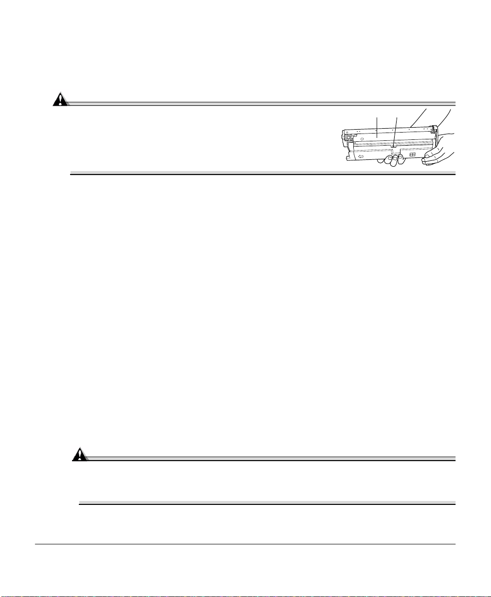
Toner Cartridge Handling
Attention
Do not hold a toner cartridge vertically. Do not touch the
toner roller surface or the protective shutte r . Th is
could lower image quality.
Keep toner cartridges:
In their packaging until you’ re ready to install them
In a cool, dry location away from sunlight (due to heat)
The maximum storage temperature is 95° F (35° C) and the maximum storage humidity is 80% without condensatio n.
Level during storage
Do not stand or stor e cartridges on their ends or turn them upside down; the toner
inside the cartridges may become caked or unequally distributed.
Away from salty air and corrosive gases such as aerosols
Away from disk drives and floppy disks
The magnets in the cartridges can damage stored data.
Toner Ca rtridge Replac eme n t
Check the message display to see what toner color is out.
1
Open the printe r ’s front cover.
2
Attention
Be careful not to spill toner on the inside of the printer’s front cover. Toner will
fall from there into the upper media tray. If toner does fall onto the open cover,
immediately wipe it with a dry, lint-free soft cotton clo th or swa b s .
Replacing Toner Cartridges 5
Page 14
If the toner cartridge you want to replace is the one showing, go to step 5. If not, go
to step 3.
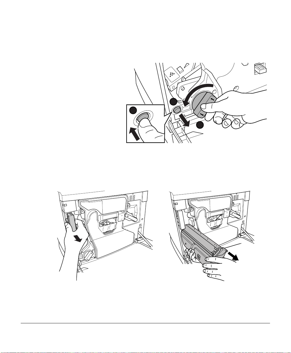
Press the toner cartridge
3
carousel button and
release the button
before turning the car-
ousel dial
counterclockwise until
it stops.
The carouse l rotates 90°
and stops.
The toner cartridge carousel may start to turn automatically from the weight of the inserted toner cartridge. Make sure you have fully
turned to the next slot before trying to insert another toner cartridge.
Repeat step 3 until the color to be replaced is visible.
4
Pull the release lever to eject the toner cartridge you are going to replace.
5
1
2
3
Dispose of it properly according to your local regulations (do not dispose of it by
burning).
Remove the new toner cartridge from its shipping carton.
6
Replacing Toner Cartridges6
Page 15
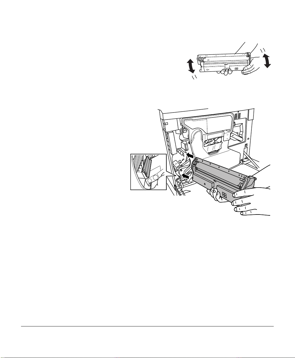
Distribute the toner inside the cartridge.
7
Holding a cartridge with both hands, gently
shake it five or six times.
Each toner cartridge has a colored end that
corresponds to a colored label inside the
cartridge sl ots. Always install t he toner cartridge in the slot with a label of the same
color.
Place the front e nd of the
8
toner cartridge insta llation guides into the cartridge inst allation rails on
the cartridge carouse l.
Gently push the new car-
9
tridge into the printer.
Close the printer’s front
10
cover.
Check the status message
11
in the message window.
If a toner alert message
is displayed, use the Service/Clear care menu to
remov e it.
Refilled Toner Cartridges
Use of consumables not manufactured by MINOLTA-QMS may cause damage to your
printer and void your warranty. If MINOLTA-QMS printer failure or damage is fou nd to
be directly attr ibutab le to the use of non- MINOLTA- QMS consumables, MINOLT A-QMS
will not repair the print er fre e of charge. In this case, standard time and materi al charges
will be applied to service your print er for that particular failure or damage.
Replacing Toner Cartridges 7
Page 16
Replacing the OPC Drum, Laser Lens Cover, and Waste Toner Pack
Attention
The OPC drum is e xtremely sensitive to bright light and direct sunlight. Always
leave it in its protective bag until you’re ready to install it. Any exposure to light
should be avoided, or permanent damage could res ult. Any damage resulting from
mishandling of the OPC drum will void the warranty of the OPC drum. Also, handle
the cartridge carefully by its sides so you don’t touch the surface (the green part) of
the drum. The drum is also extremely sensitive to hand oils and scratches, both of
which reduce print quality.
When the OPC drum i s worn out, the mess age
not print until the drum kit is replaced.
When you replac e the OPC drum cartridge after a
message displays i n the me ssage w indow, the printer automatic all y r ec overs. Howe ver, the
replac ed waste toner pack consumables monitoring syste m must be reset.
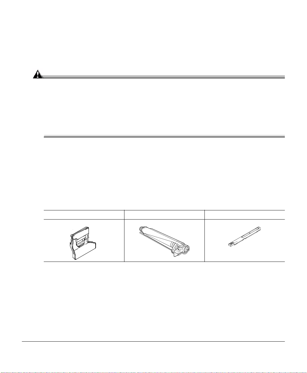
The three items below are include d in the OPC drum kit. If one needs replacing, replace
all three items.
Waste toner pack OPC drum cartridge Laser lens cover
The OPC drum life is directly relate d to the number of rota tions of the drum. Longest
drum life is achieved with continuous printing. Intermittent pr inting with small job size s
requires cleaning rotations before and after each job, and subsequently will impact OPC
life.
The steps are:
Removing the used waste toner pack
REPLACE DRUM
DRUM LOW or REPLACE DRUM
appears. The printer will
Removing the used OPC drum cartridge
Replacing the OPC Drum, Laser Lens Cover, and Waste Toner Pack8
Page 17
Removing the laser lens cover
Installing the las er le ns cover
Installing the new OPC drum cartridge
Installing the new waste toner pack
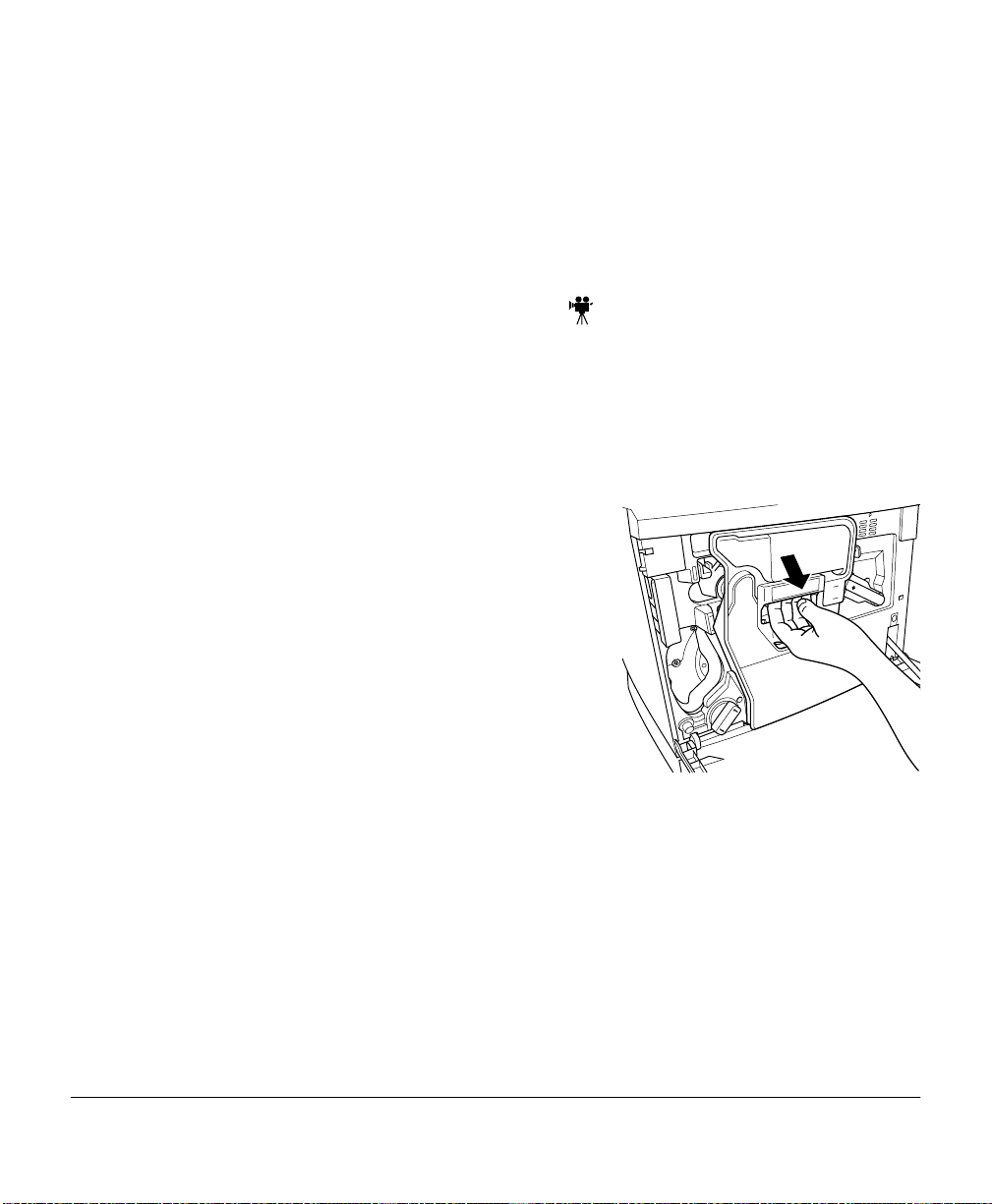
Removing the Used Waste Toner Pack
When the waste toner pack is nea rly full, the message “
appears. Prepare to replace the entire OPC drum kit.
Turn off the printer.
1
Open the printe r ’s front cover.
2
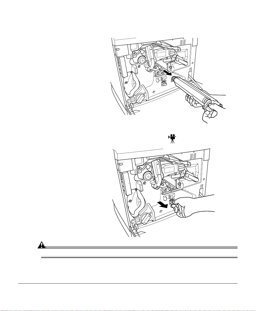
Carefully remo ve the wa ste to ner p ack using t he
3
handle.
Keep the waste toner pack upright so the toner
does not spill.
WASTE TONER NEAR FULL
”
Replacing the OPC Drum, Laser Lens Cover, and Waste Toner Pack 9
Page 18
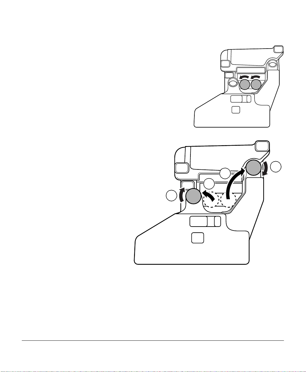
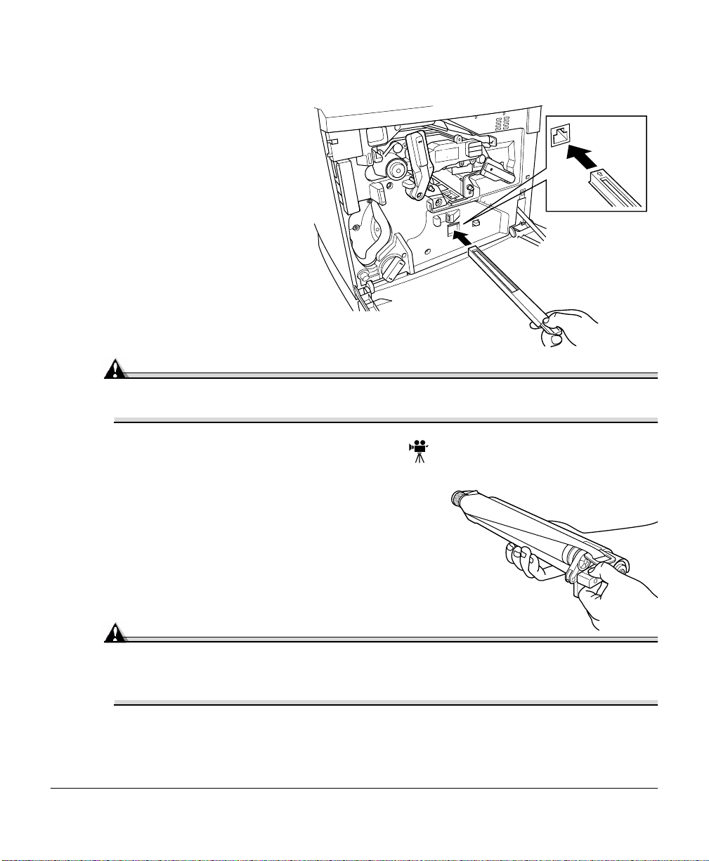
Turn the two caps labeled “A” count erclockwise
4
and remove them.
T wist the two “A” cap s
5
onto the two
holes labelled “A.”
Turn the caps clockwise
to secure them.
2
2
A
1
1
1
1
AA
A
2
2
Replacing the OPC Drum, Laser Lens Cover, and Waste Toner Pack10
Page 19
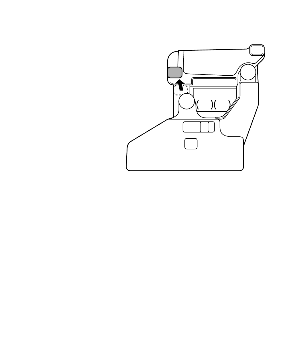
Remove waste toner pack
6
cap labeled “B” and
insert it into hole “B.”
Dispose of the used
7
waste toner pack.
Dispose of it properly
accor ding to your local
regulations (do not
dispose of it by burning).
Continue with replaci ng
8
the OPC drum
cartridge.
Reinstall the new waste
toner pack after replacing the OPC drum.
B
Replacing the OPC Drum, Laser Lens Cover, and Waste Toner Pack 11
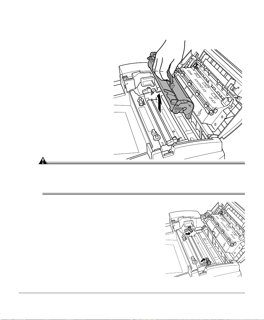
Page 20
Removing the Used OPC Drum Cartridge
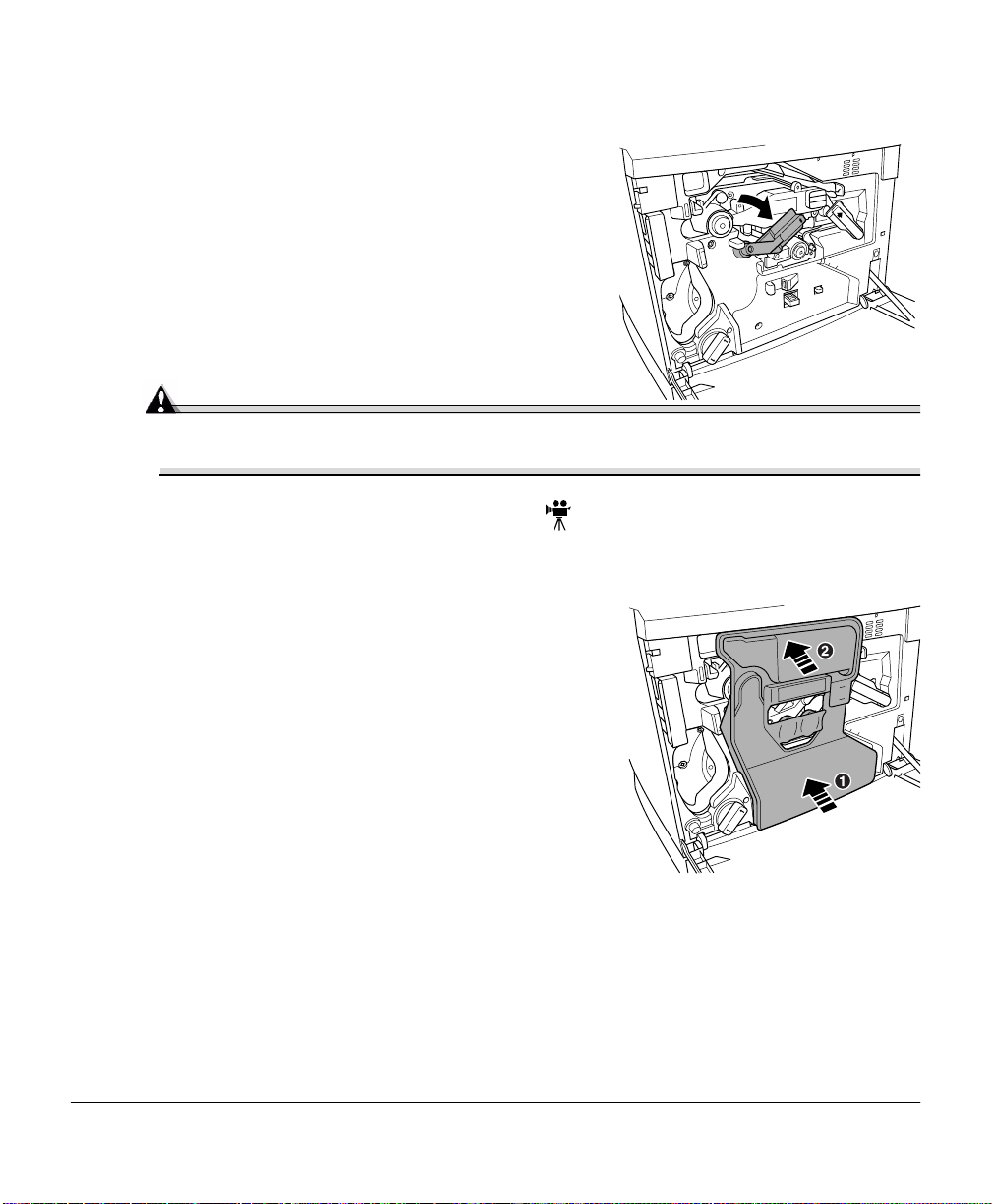
With the front cover
1
open, rotate the transfer
belt unit left r elease le ver
counterclockwise to the
top (12 o’clock)
position.
This raises the transfe r
belt unit.
Hold the OPC drum car-
2
tridge handle with your
left hand and carefully
pull it out about 8 inches
(20 cm).
Replacing the OPC Drum, Laser Lens Cover, and Waste Toner Pack12
Page 21
Keep your left hand in
3
place and support the
bottom of the drum with
your right hand, then
carefully pull the cartridge toward you and
remove it.
Dispose of it properly
accor ding to
your local r egulations.
Removing and Installing the Laser Lens Cover
Press on the laser lens
1
cover lock release lever
and gently pull the laser
lens cover toward you.
Dispose of it properly
accor ding to your local
regulations.
Remove the new laser
2
lens cover from the OPC
drum kit box.
Attention
Do not touch the glass surface of the laser lens.
Replacing the OPC Drum, Laser Lens Cover, and Waste Toner Pack 13
Page 22
Place the front e nd of the
3
laser lens cover into its
installation rail.
Carefully insert the laser
4
lens cover and make sure
it is fully inserted.
Attention
If the laser lens cover is not proper ly in stalled, serious damage to the printer
could result.
Installing the New OPC Drum Cartridge
Remove the new OPC drum cartridge from its
1
shipping box.
Attention
Keep the protective sheet on the cartridge. Do not touch the protective sheet on
the photosensitive (green) surface or scratch the surface. This could lower
image quality.
Make sure the transfer belt left release lever is still set to its top position (12
o’clock).
Replacing the OPC Drum, Laser Lens Cover, and Waste Toner Pack14
Page 23

Hold the OPC drum car-
2
tridge level, pl ace t he
front end of the OPC
drum cartridge installation guide into the installation rail.
Carefully push the OPC
3
drum cartridge in.
Attention
The cartridge should slide easily into the printer. Don’t force it.
Press on the front handle
4
of the OPC drum cartridge with one hand and
hold the front handle of
the OPC protective c over
with the other hand.
Peel the protective cover
5
off (straight toward you).
Dispose of it properly
accor ding to your local
regulations.
Replacing the OPC Drum, Laser Lens Cover, and Waste Toner Pack 15
Page 24
Turn the left release lever o f the tran s fer belt
6
clockwise to its correct position (2 o’clock).
This lowers the transfer bel t.
Also make sure the transfer belt right release
lever is set to its correct position (10 o’clock).
Attention
If the transfer belt left release lever is at its top position (12 o’clock) , t he waste
toner pack cannot be installed.
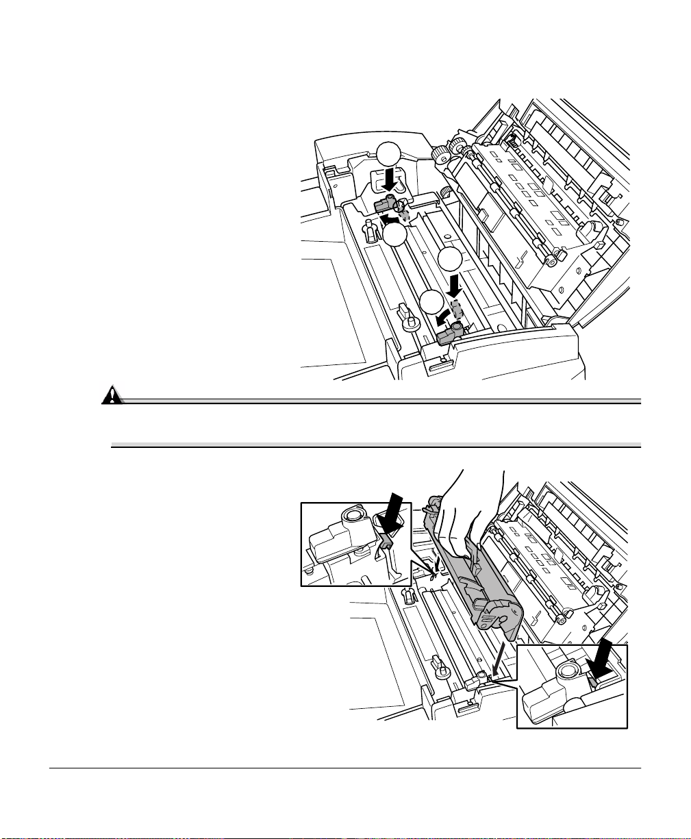
Installing the New Waste Toner Pack
Remove the new waste toner pack from the drum kit box.
1
Insert the bottom of the waste toner pack into
2
its installat ion position in the print er.
Insert the top of the waste toner pac k
3
into its installat ion position in the printe r until it
is firmly seated .
2
Close the printer’s front cover.
4
If the waste toner pack is not cor rectly installed
or the transfer belt right release lever is at its
top position (12 o’clock), the front cov er cannot
be closed.
Turn on the printer.
5
Check the status message in the message window.
6
If an OPC drum or waste toner alert message is displaye d, use the Service/Clear
care menu to remove it.
Replacing the OPC Drum, Laser Lens Cover, and Waste Toner Pack16
1
Page 25
Replacing the Fuser Unit and Transfer Roller Kit
WARNING!
The fuser unit is hot. When the top cover is opened, the fuser unit temperature
drops gradually (one hour wait time). Do not replace the fuser oil roller until you
are sure that the fuser un it has cooled down.
When the fuser is worn out, the message “
printer does not print. Replace the fuser kit.
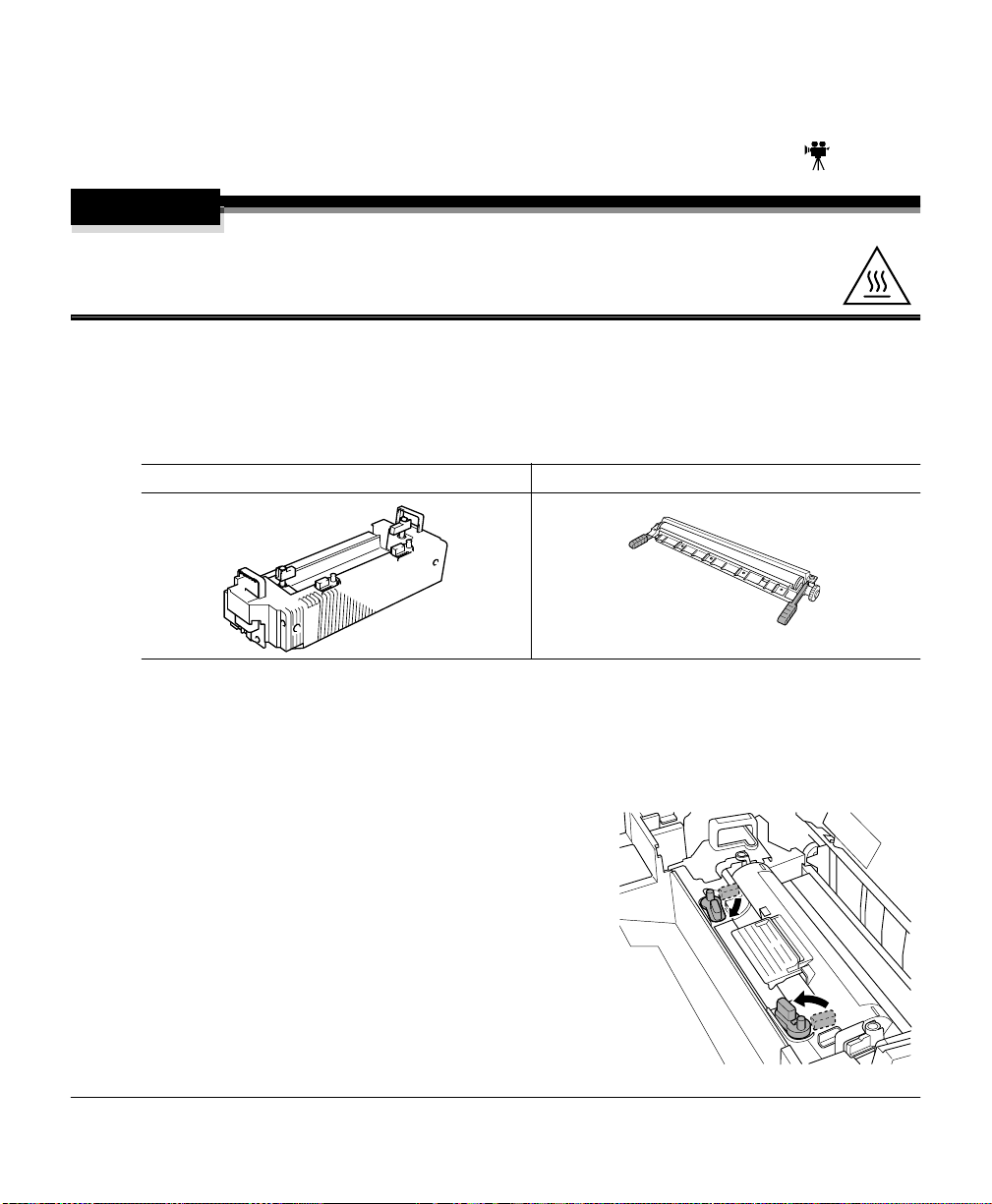
The fuser kit includes the two ite ms below. When replacing the fuser unit, replace the
transfer roller as well.
Fuser unit Tr ansfer roller unit
REPLAC E FU SE R UNI T
” appears, and the
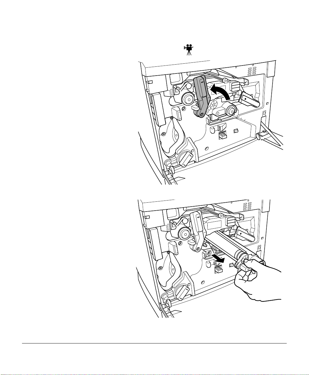
Replacing the Fuser Unit
Turn off the printer.
1
Open the printer’ s top cover.
2
Rotate the two fuser oil roller lock levers to
3
release the fus er oil ro ller.
Replacing the Fuser Unit and Transfer Roller Kit 17
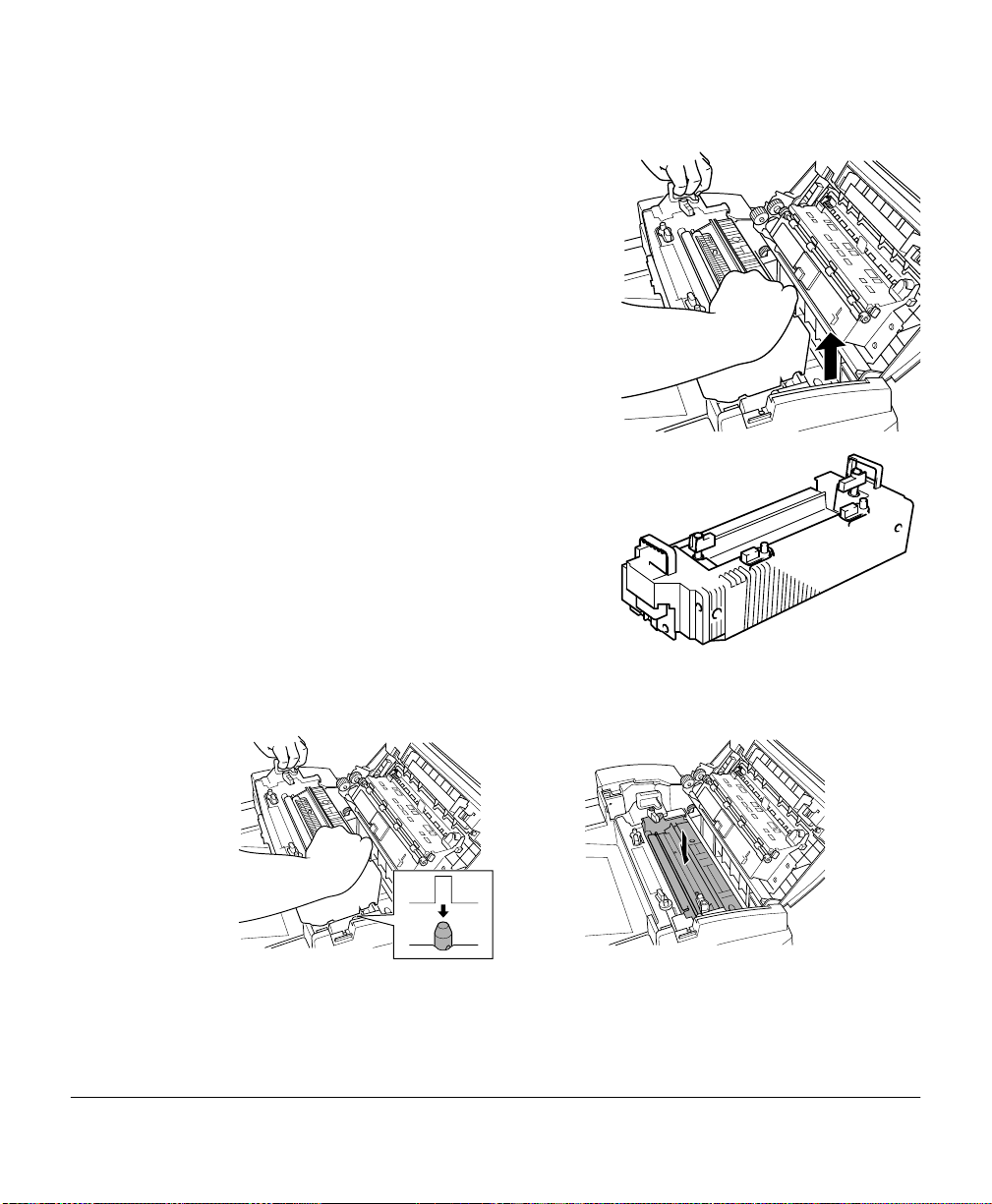
Page 26
Remove the fuser oil
4
roller.
Hold it by the green
handle only.
Place the fuser o il roller
5
on a level surface.
Attention
Since the fuser oil roller removed here is to be installed in the new fuser unit,
handle it with ca re. If you set the fus er oil rolle r on the tabl e, do it as sho w n in
the illustration. Do not allow the roller surface to contact the table or get dirty.
This could lower image quality.
Turn the rel ease levers to release the fuser unit.
6
Replacing the Fuser Unit and Transfer Roller Kit18
Page 27
Holding the fuser unit handle s, lift up
7
the unit.
Dispose of it properly according to your local
regulations.
Remove the new fuser from its shipping box.
8
Carefully lower the new fuser unit so that the two pins in the fus er unit installa tion
9
section go into the two instal lat ion holes in the fuser unit.
Replacing the Fuser Unit and Transfer Roller Kit 19
Page 28
Press down on the fuser
10
unit release lever s and
rotate them .
1
This secure s the fuser
unit.
Attention
If the fuser unit release levers are not set correctly, the fuser oil roller cannot be
installed. Set the fuser unit release levers to the fixed position.
Reinstall the fuser oil
11
roller (removed in
step 4).
1
2
2
1
1
2
2
Replacing the Fuser Unit and Transfer Roller Kit20
Page 29
Rotate the two oil roller lever s to loc k the oil
12
roller into place.
Close the printer’s top cover.
13
Check the status message in the message window.
14
If a fuser unit alert message is displ ayed, use the Service/Cl ear car e menu to r emove
it. Check the release button to make sure the top cover is properly closed.
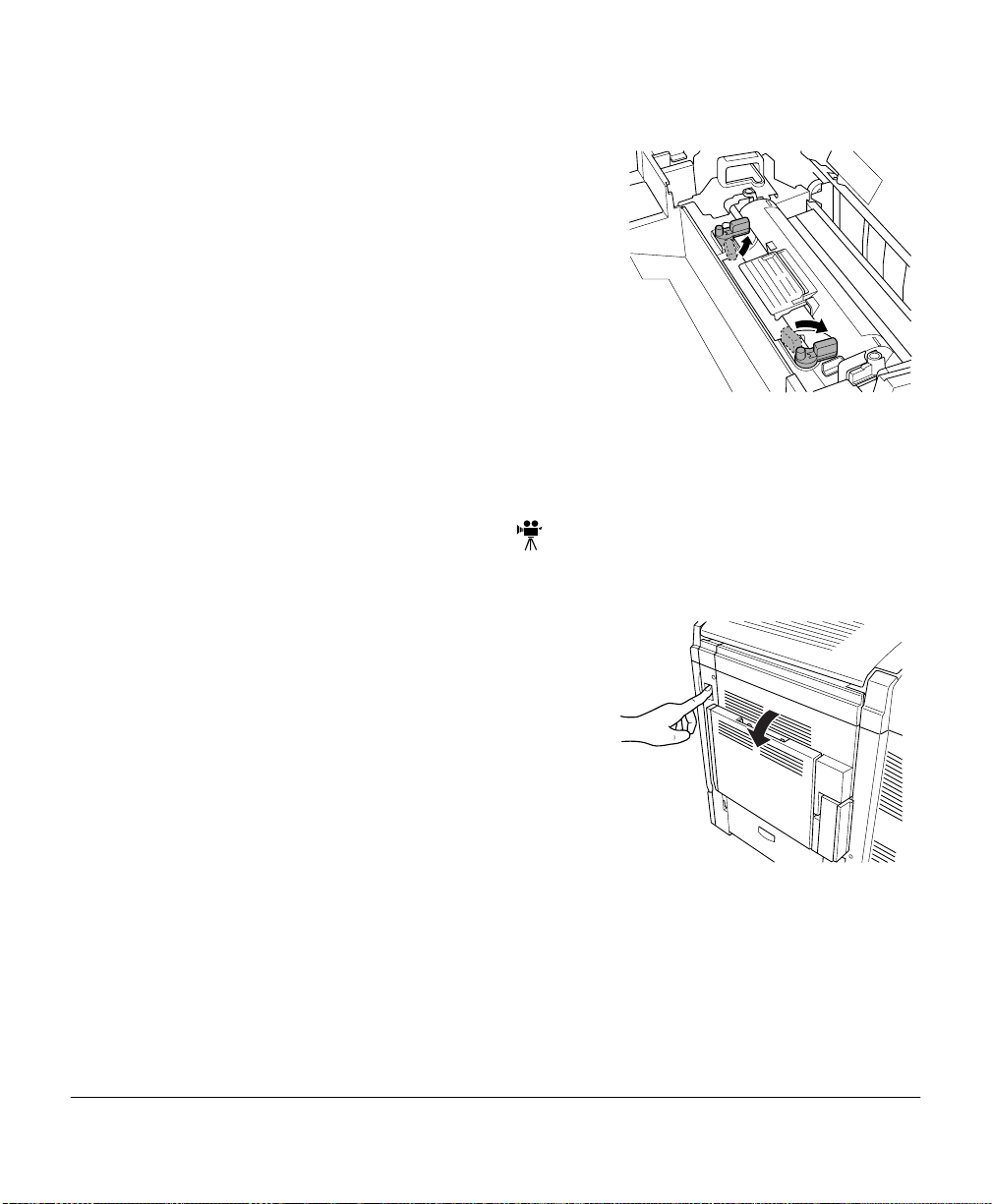
Replacing the Transfer Roller Unit
If there is media in the multipurpose tray , remove it. Close the multipurpose tray.
Press the right cover release button and care-
1
fully open the right cover.
Replacing the Fuser Unit and Transfer Roller Kit 21
Page 30
Holding the two transfer
2
roller unit handles,
remove the transfer roller
unit.
Dispose of it properly
accor ding to your local
regulations.
Remove the new tr ans fer
3
roller unit from the fuser
kit box.
Attention
Do not touch the surface of the transfer roller unit. This could lower
image quality.
Place the new transfer roller unit on a level surface.
4
Lift up the two transfer roller unit handles.
5
Replacing the Fuser Unit and Transfer Roller Kit22
Page 31

Holding the two transfer
6
roller unit handles, carefully lower it so the
transfer roller unit shaft
goes into the two transfer roller unit ins tallation
guides.
Lower the two transfer
7
roller unit handles.
Carefully close the right
8
cover.
Check the re lease button
status to make sur e the
cover is properly closed.
If necessary, reopen the
9
multipurpose tray a nd put
the media back in.
Replacing the Fuser Unit and Transfer Roller Kit 23
Page 32

Check the status message in the message window.
10
If a transfe r roller alert message is displayed, use the Service/Clear care menu to
remov e it.
Replacing the Fuser Oil Roller
The fuser oil roller provide s a lubricant for the printer via an oil-impregnated roller. This
oil is necessary for the proper functioning of the printer.
WARNING!
The fuser unit is hot. When the top cover is opened, the fuser unit temperature
drops gradually (one hour wait time). Do not replace the fuser oil roller until you
are sure that the fuser un it has cooled down.
When the fuser oil roller is worn out, the message “
and the printer does not print. Replace the fuser oil roller.
Turn off the printer.
1
Open the printer’ s top cover.
2
Rotate the two fuser oil roller lock levers to
3
release the fus er oil ro ller.
REPLACE OIL ROLLER
Dispose of it properly according to your local
regulations.
Remove the new fuser oil roller from its
4
shipping box.
Attention
If you set the new fuser oil roller on a table, do it as shown in
the illustration. Do not allow the roller surface to contact the
table or get dirty. This could lower image quality.
Replacing the Fuser Oil Roller24
” appears
Page 33

Insert the new fuser oil
5
roller install ation guides
(front, rear) into the fus er
unit installat ion rail.
Carefully lower the
6
roller.
Rotate the two oil roller
7
levers to lock the oil roller into place.
Attention
If the two fuser oil roller release levers are not corr ectly set, the top cover
cannot be closed. Set the release levers to the roller fixed position.
Carefully close the top cove r.
8
Check the re lease button to make sure the top cover is properly closed.
Replacing the Fuser Oil Roller 25
Page 34

Turn on the printer.
9
Check the status message in the message window.
10
If a fuser oil r oller alert message is displayed, use the Service/Clear care menu to
remov e it.
Replacing the Transfer Belt
When the transfer belt is at its end of life, the message “
appears, and the printer does not print. Replace the transfer belt. After the new transfer
belt is installed, printing automatically resumes.
Open the printe r ’s front
1
cover.
Remove the waste toner
2
pack.
Rotate the left tr ans fer
3
belt lock lever as shown
in the illustration.
REPLACE TRANSFER BELT
”
Replacing the Transfer Belt26
Page 35

Remove the OPC drum
4
cartridge and set it aside.
Attention
The OPC drum is extr emely s ensitive to bright light and dir e ct sunligh t. Al ways
put it in its protective bag until you’re ready to reinstall it. Any exposure to
light should b e avoided, or permanent damage could result.
Also, handle the cartridge carefully by it s sides so you do n’t touch the surface
(the green part) of the drum. The drum is also extremely sensitive to hand oils
and scratches, both of which reduce print quality.
Rotate the left lever to its
5
4 o’clock position.
Replacing the Transfer Belt 27
Page 36

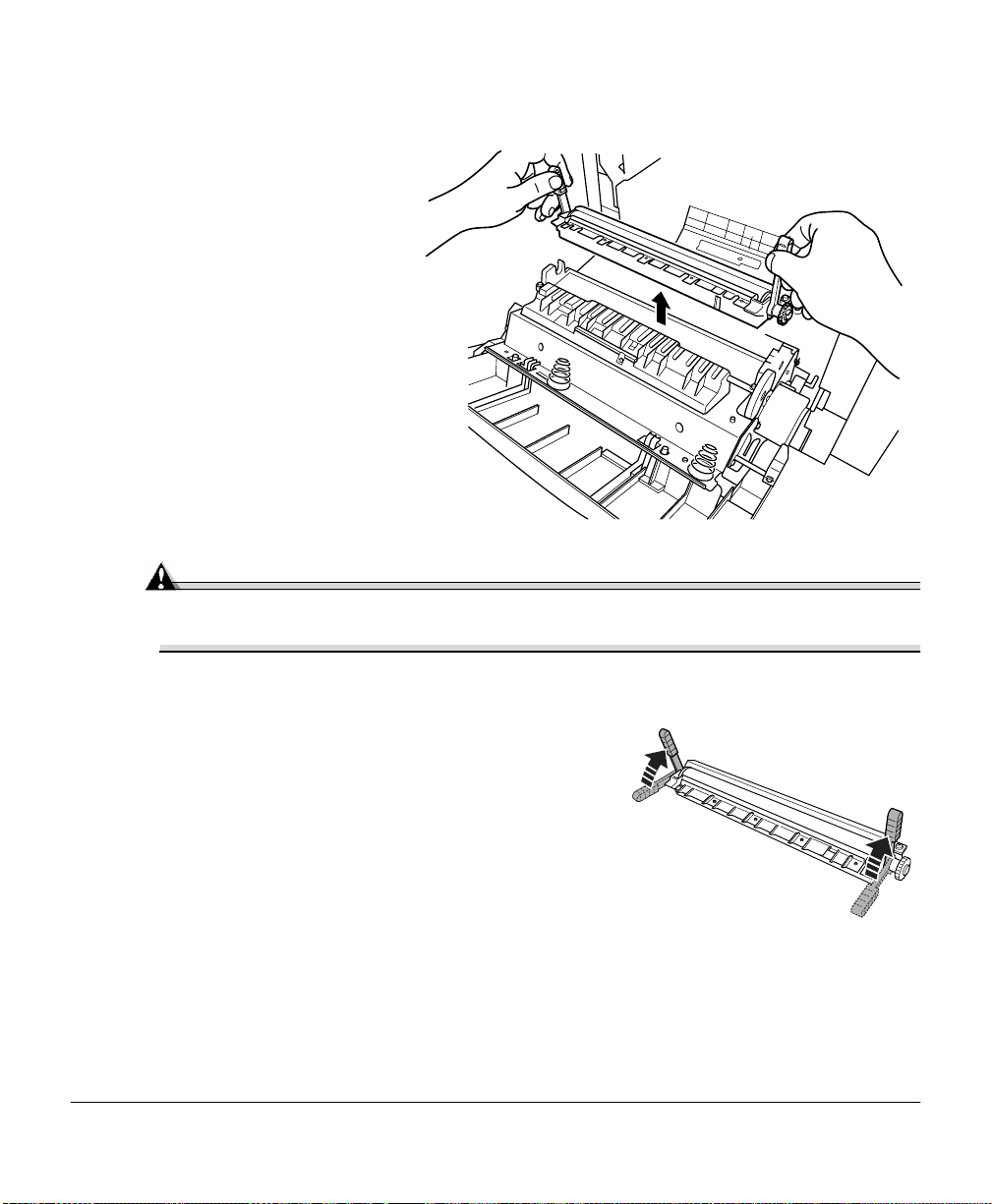
Grasp the handles of the transfer belt and remove it.
6
Dispose of it properly according to your local regulations.
Remove the new tr ans fer
7
belt from its packaging
and insert it into the
printer.
Replacing the Transfer Belt28
Page 37

Press on the transfer belt
8
front handle with one
hand, take the handle of
the transfer belt fi xtur e
with your other h and, and
pull the fixture stra ight
toward you.
Dispose of it properly
accor ding to your local
regulations.
Rotate the transfer bel t
9
lock levers.
Replacing the Transfer Belt 29
Page 38

Reinstall the OPC drum
10
cartridge.
Close the transfer belt
11
lock lever.
Make sure the laser lens
12
cover is firmly s eated .
Replacing the Transfer Belt30
Page 39

Reinstall the waste toner
13
pack.
Close the f ront cover and
14
turn on the printer.
Check the status message
15
in the message window.
If a transfe r belt alert
message is displaye d, use
the Service/Clear care
menu to remove it.
2
1
Replacing the Transfer Belt 31
Page 40

Page 41

Using Media
2
Page 42

Introduction
This chapter provides information on handling, selecting, and storing media. Refer to the
Maintenance Guide
Media Handling
Before purchasing a large quantity or special media, do a trial printing with the same
media and check pr int qua lity. Check with our web site www.minolta-qms.com for a lis t of
current approved media.
Attention
Do not use the media types listed below. These could cause poor print quality, media
jams, or damage to the printer.
Do not use media that is Do not use labels that have
Not approved Label(s) already peeled off
Meant for ink jet printers Labels that peel off easily
Folded, embossed, warped, or wrinkled Glue or sealer that might come off
Perforated or prepunched
Too slick, too coarse
Coated with a process ed s urface ( such as car bon
paper, heat-sensitive paper, heat-pressure paper)
Composed of foil or gilt Sticky flaps
Irregularly shaped (not rectangular); not uniform
in size
Bound with glue, tape, or pape r clips
Attached to ribbons, hooks, buttons, etc.
Made of material that will melt, vaporize, off set
discolor, or emit dangerous fumes
for media spe cifications.
Do not use envelopes that have
Metal clasps, fasteners, transparent windows,
peel-off st rips for sealing
Introduction34
Page 43

Media Types
Plain Paper
Formatting
Input Upper and
Orientation Upper and
Type
Weight
Duplexing
Format data within your application.
Optional T rays
Multipurpose
Tray
Optional T rays
Multipurpose
Tray
Any standard or rec ycled office paper suitable for plain-pa per laser printers,
such as
Hamme rm i ll L as e r P ri nt
Georgia-Pacific Microprint Laser 1000
Neusiedler Color Copy 90
Xerox 4024
16–24 lb bond (60–90 g/m²)
Up to 28 lb bond (105 g/m²)
Letterhead and Memo Media
Formatting
Input Upper and
Orientation Upper and
Format lette rhead or memo data withi n your application. Try printing your data on
a plain sheet of paper fi rst to check placement.
Optional Trays
Multipurpose
Tray
Optional Trays
Multipurpose
Tray
500 sheets of 20 lb bond (75 g/m²) paper (letter/A4/le gal)
each; capacity for other weights var ies accordingly.
150 sheets of 20 lb bond (75 g/m²) paper; capacity for other
weights vari es accordingly.
Simplex—Face up; Du plex—Face down
Simplex—Face down; Duplex—Face up
Up to 500 sheets
Up to 150 sheets
Face up—top of page toward the right
Face down—top of page toward the printer side
Media Types 35
Page 44

Type
Weight
Duplexing Upper and
Notes
Thic k Stock
Any standard or recycled office paper suitable for plain-paper laser printers,
such as
Hammermill Laser Print
Georgia-Paci fic Microprint Laser 1000
Neusiedler Color Copy 90
Xerox 4024
16–24 lb bond (60–90 g/m²)
Face down—top of page toward the right
Optional Trays
Multipurpose
Tray
Check your appl ication documentation for other information about printing on
letterhead and memo medi a.
Face up—top of page toward the printer side
Formatting
Input Multipurpose
Orientation
Type
Weight
Duplexing
Notes
Format the inf ormation to be pri nted on the thi ck stock within your application. T ry
printing your data on a pla in sheet of paper first to check placement.
Tray Only
Face down
For information about thick stock media recom me nded for your printer, go to
www.minolta-qms.com/support, then click on Answer Base, or contact Technical
Support. See the
telephone numbers.
Simplex: 24–43 lb bond (90–163 g/m²)
Autoduplex: Up to 28 lb bond (105 g/m²)
Manual Duplex: 24 lb (90 g/m²) to 43 lb (163 g/m²) bond
Autoduplexing th ick stock over 28 lbs (105 g/ m² ) i s not supported. Thicker stock
may be manually duplexed.
Y ou sh ould tes t the number of sheets of thick stock the multipu rpose tr ay can hold
to ensure that its performance is acceptable.
43 lb (163 g/m²) bond is also referred to as 90 lb index stock.
Up to 50 sheets, dependi ng on the t hickness of the media
Service & Support Guide
for a complete listi ng of support
Media Types36
Page 45

Envelopes
Formatting
Y our printer receives the instructi ons to print on envelopes fro m you r application.
Input Multipurpose
T ray O nly
Orientation
Type
Face down
Use common office envelopes approved for laser printing with diagonal joints,
sharp folds and edges, and ordinary gummed flaps, such as
Duplexing
Notes
Not supported
Labels
Formatting
Input Multipurpose
Orientation
Type
Format label data withi n your application. Try pri nting your data on a plain sheet
of paper first to chec k placement.
Tra y Only
Print on th e front side only. Some parts of t he env elope c onsist of t hree l ayer s
of paper—the front, back, and flap. Anything printed in these layered regions
may be lost or faded.
See your application documentation for specific information on printing
envelopes.
Up to 50, depending on the thickness of the envelopes
Commercial #10: Columbian Recycled COR02
International DL: Auto Fil #01914
You can print
Envelopes should be dry.
Do not preload or preseal envelopes.
Face down
Use only labels recom me nded for laser printers, such as
on the address side of the envelope.
only
Up to 50 sheets, dependi ng on the t hickness of the labels
Avery 5260
Weight
Duplexing
16–90 lb (60–163 g/m²)
Not supported
Media Types 37
Page 46

Notes
Postcards
Avoid using la bels with exposed adhesive ; it ma y sti ck to the tran sfer belt or
the fuser roller, causing labels to peel off and media jams to occur.
Adhesive label stock is supported only in letter or A4 sheets.
A label consis ts of a face s heet (the pr inti ng surf ace), ad hesive, and a c arri er
sheet
— The face sheet must follow the plain paper specification.
— The face sheet surface must cover the entire carrier sheet, and no
adhesive should come through on the surface.
You can print continuously with label paper. However, this coul d affect the
media feed, dependi ng on the media quality and printing environm ent. If
problems occur, stop the continuous print and print one sheet at a time.
Check your appl ication documentation for other information on
printing labels.
Formatting
Input Multipurpose
Orientation
Type
Weight
Duplexing
Notes
Format postcard data with in your application. Try printing your data on a plain
sheet of paper first t o check placement.
16–90 lb (60–163 g/m²)
Not supported
Transparencies
Formatting
Format the i nformation to be printed on the transparencies within your
application. Try printing your data on a plain sheet of paper first to check
placement.
Up to 50 sheets, depending on the thickness of the postcards
Tr ay On ly
Face down
Use only postcards re com m ended for laser pri nters
If the postcard is warped, press on t he warped area before
putting in multipurpose tray.
Media Types38
Page 47

Input Location
Capacity
Orientation Upper and
Optional Trays
Multipurpose
Tray
Type
Duplexing
Notes
Use any full-color transparencies (also known as OHP film) that meet normal
photocopier standards. We recommend
Q-Media T ransparency Media for th e mag icolor 2200 for color printi ng
3M PP2500 for monochrome printing
Not supported
If you touch the face of transparencies with your bare hands, print qual ity
may be affected.
Do not handle trans parency media too muc h. Do not fan transpar ency media
before loadi ng it . Resulting static electrici ty may cause printing errors.
Keep the media path clean. T ranspa renc ies are espec ially sen si tive to a di rty
media path. If there are shadows on either the top or the bottom of the
sheets, see
You can print continuously with transparencies. However, this could affect
the media feed, depending on the media quality and pr inting environment. If
problems occur, stop the continuous print and print one sheet at a time.
Check your appli cati on doc umentati on for other i nformat ion about pr inting on
transparenc ies.
Upper and Optional Trays
Multipurpose tr ay
Up to 50 sheets, depending on the thickness of the
transparencies
If you have problems feeding 50 sheets, try loading only 5–10
sheets at a time. Loading a lar ge num ber of transparencies at
a time may cause static buildup, thus causing feeding
problems
Face up
Face down
“Printer Care” on page 80.
.
Media Types 39
Page 48

Loading Media
Take off the top and bottom sheets of a ream of paper.
Holding a stack of approximately 250 she ets at a time,
fan the stack to prevent static buildup for the paper
before inserting it in a tray.
Attention
Always load the media short edge first.
Attention
Do not mix media of different sizes, types, or weights, as this will cause
printer jamming.
When refilling media, first remove any media remaining in the tray. Stack it with the
new media, even the edges, then reload it. Although the magicolor 2200 DeskLaser
was designed for printing on a wide range of media types, it is not intended to print
exclusively on a single media type except pla in paper. Con tinuous printing on media
other than plain paper (such as envelopes, labels, thick stock, or transparencies) may
adversely af fect print quality or reduce engine life.
For media other than standard plain paper or transparencies, both the driver (Paper
tab, Paper Type option) and the MP Size key on the control panel need to be selected.
It is important to use the MP Size key to set the multipurpose tray to the appropriat e
media size in or der to obtain optimum printing re sults.
Autoduplexing
Duplex (2-sided) printing can be done automatic ally with the optional duplex unit
installed.
Only up to 28 lb bond (105 g/m²) plain paper can be duplexed.
Loading Media40
Page 49

If you are printing duplex from the upper or optional tray, load the media printing-side
down with the top of the media (or letterhead or memo informat ion) toward the right side
of the tray. If you are printing duplex from the multipurpose tray, load the media
printing-sid e up with the top of the media toward the printer . Set the driver, for example:
In the printe r driver, make sure you have selected Duplexer and clicked on the
1
Add button.
In the printer driver, select Simplex (one-sided pages), or Long Edge (flipped hori-
2
zontally as in a loose-lea f notebook), or Short Edge (fli pped vertically as on a clipboard) as the Duplex option.
Click OK.
3
Upper and Optional Media Trays
Slide the media tray open.
1
Push the media pr essure plate down to lock it in
2
position.
Loading Media 41
Page 50

Adjust the media guides to fit the size paper you’re loading.
3
Squeeze the retainers, move the guides to the appropriate location (media sizes are
listed on the tray), and release the retainers. The media should fit easily between
the guides.
Load the paper face-up, short edge toward the
4
right of the tray.
Often, an arrow on the media package label
indicates the printing-side of the media.
Do not overfill the tray.
A fill limit mark is provided on the inside of the
tray. The media tray holds 500 sheets of 20 lb
bond (75 g/m²) paper.
Loading Media42
Page 51

Make sure that the paper
fits easily between the
guides and the paper
corners ar e under the
left and right
media-separating tabs
and are not bent.
Attention
Always readjust the media gui des afte r inserting the media. Improperly
adjusted guides may cause poor print quality, media jams, or printer damage.
Slide the tray back into
5
the printer.
If you have removed the
tray from the printer,
slightly tilt up the tra y to
insert it into the
installatio n rails to slide
it bac k in .
Loading Media 43
Page 52

Multipurpose Tray
Page sizes other than lette r, A4, and legal can be printed only from the multipurpose tray
(also known as tray 1). Use the printer drive r to set the page size.
Other special types of media (such as thick stock, transparencies, and envelopes) are also
fed from the multipurpose tray. See “Media Specifications” in the
more information about media.
Open the multipurpose tray on the right side of
1
the printer.
Open the media support.
2
Maintenance Guide
for
Attention
Load only one type/size of media per tray at a time.
Loading Media44
Page 53

Load the media face
3
down, short edge toward
the printer.
Often, an arrow on the
paper package label
indicates the face-up
(printing) side of the
paper.
A fill limit mark is provided on the inside of the
media guides on the multipurpose tray. The
multipurpose tray holds 150 sheets of
20 lb bond (75 g/m²) paper.
Adjust the media gu ides to
4
fit the size media you’re
loading.
FACE
DOWN
EXE.
LGL.
LTR.
A5
B5
A4
Attention
Always adjust the media guides after inserting the media. A guide that is not
properly adjus ted can cause poor prin t qualit y , media jams, or prin ter damage.
Specify the media size in the multipurpose tray by using the printer driver.
5
Loading Media 45
Page 54

Printing Envelopes from the Multipurpose Tray
Flex the envelope stack (inc luding the edges) to remove any stiffness.
1
Place the e nvelopes on a flat surface, and flatten them by pressing down the corners.
2
Correct any bent corners, and then tap the envelopes on a flat surface to align them.
3
Place the envelope stack int o the multipurpose tray with the flap-side up.
4
Check your application docume ntation to determi ne if the flap should be placed on
the left or on the right. Print a single enve lope to check the orientation befor e printing multiple copies.
Adjust the media guides to the width of the envelopes.
5
Make sur e the guide s ar e snug enough to ke ep the en velopes s traigh t, but not so ti ght
that they buckle the envelope s.
Open the flap of each envelope immediately (before it cools) after the envelope is
6
delivered to the output tray.
Because the envelopes pass through heated rollers, the gummed area on the flaps
may seal. Using envelopes with emulsion-based glue avoids this problem.
Loading Media46
Page 55

Printi ng Area
The printing area on all media sizes is up to about
0.157 inch (4 mm) from the edges of the media.
4 mm
4 mm
4 mm
Media Storage
When storing media, avoid:
Direct sunlight
Excess heat and humidity
Dust
If media has been removed from its wrapper, place it in its original packaging and store in a
cool, dark place on a level surface.
4 mm
Media Storage 47
Page 56

Page 57

Printer Driver
Configuration
3
Page 58

Introduction
The magicolor 2200 DeskLaser prin ter driver is for use with Windows Me/2000 /NT4/98/
95 operating systems. This chapter describes how to configure the printer driver and the
MINOLTA-QMS Crown Print Monitor. We’ve also included information about using the
MINOLTA-QMS Printer Status Monitor.
Configuring the P rinter Driver
This section explains how to access and conf igure the magicolor 2200 DeskLaser printer
driver.
The printer configura tion options are locate d on tab s that appear in the magicolor 2200
DeskLaser printe r driver window. To a ccess options for viewing or modification, op en the
printer driver windo w and click on the tab appropr iate for your needs. Online help is also
available while you’re configuring the printer driver. Just choose any Help button.
Windows Me/98/95 Configuration Methods
If you’re using Windows 2000/NT 4, refer to “Windows 2000/NT 4 Configuration
Methods” on page 52 for complete informat ion.
Introduction50
Page 59

There are two methods of accessing the configur ation options of the printer driver:
... via the printer device properties ... via your application’s pri nter setup
Gives you access t o all printer settings Gives you access to Paper, Page Layout,
Image, Device Option, and About tabs.
Lets you assign the def ault printer settings for
all print jobs
Retains your settings until changed again via
properties
How To:
Lets you assigns the printer settings for only
the current pr int job
Temporarily overrides t he existing default
settings
How T o:
1 From the Windows Start menu choose
Settings.
2 Choose Printers.
3 Select t he mag icolor 2200 DeskLaser
printer driver.
4 From t h e F i le menu, ch oose Prop erties .
5 Make your selections, and then choose
OK to save your changes.
6 Close the Print ers window.
1 From the applic ati on’s File menu choose
Print (or, in some cases, Print Setup or
Page Setup).
2 In the Print, Print Setup, or Page Setup
dialog box, select the magicolor 2200
DeskLaser print er driver.
3 Choose the Propert ies button.
4 Make your selections, and then choose
OK to save your changes.
5 Choose OK from the Print Setu p window.
You should configure your printer driver settings via the printer driver properties
method for your typical print jobs and use your applic ation’s printer setup method for
print jobs that r equire special, less freque ntly needed printer settings.
The tabs and a summary of the options found on each are as follows:
General—Allows you attach comments, use a separator page, and print a test page.
See your Windows documentation.
Details—Allows you to set interface c onne ction details. See y our Windows documen-
tation.
Sharing—Allows you to set up the printer so others on the network can use it. See
your Windows doc umentation.
Configuring the Printer Driver 51
Page 60

Color Management (Windows 98 only)—Allows you to select the col or profile
associated with your pri nter or allow the operating system to make the selection for
you.
32-bit Super D ri ver Setup—This tab leads to the following set of tabs that are also
available from your applic ation’s printer setup properties. See “32-bit SuperDriver
Setup” on page 55.
Paper—Allows you to provide information about the document type and loca tion
of the media you want to print on. See “Configuring Pape r Opti ons” on page 56.
Page Layout—Allows you to specify N-up (Number-up) settings, scaling and
watermarks used for your print jobs. See “Configuring Page Layout Options” on
page 63.
Image—Allows you to provide settings f or color format, image brightness and
contrast, color balance, and color matching. See “Configuring Image Options” on
page 70.
Device Options—Allows you to specify which printer options are installed on
your printer. See “Configuring Device Options” on page 74.
About—Displays the magicolor 2200 DeskLase r printer driver r elea se version
and date. See “Information on the About Tab” on page 75.
Windows 2000/NT 4.0 Configuratio n Methods
If you’re using Windows Me/98/95, refer to “Windows Me/98/95 Configuration
Methods” on page 50 for complete informat ion.
Configuring the Printer Driver52
Page 61

There are three methods you can use to configure the printer driver. However, these three
methods don’t all have the same options or control.
... via the printer driver properties ... via your applicat ion’s printer setup
Gives you access to the General, Ports,
Scheduling (Windows NT 4.0) or Advanced
(Windows 2000), Sharing, Sec urity, and About
tabs
Lets you assign the printer settings for all print
jobs
Retains your settings until changed again via
properties
How To:
Gives you access to the Paper, Page Layout,
Image, Device Opti ons, and Abou t tab s
Lets you assigns the printer set tings only for
the current pr int job
Temporarily overrides the existing default document settings
How To:
1 From the Windows Start menu choose
Settings.
2 Choose Printers.
3 Select the magicolor 2200 DeskLaser
printer driver.
4 From the File menu, choose Properties.
5 Make your select ions, and then choose
OK to save your changes.
6 Close the Printers window.
... via document def aults (Windows NT 4.0) or via printi ng preferences (Windows 2000)
Gives you access to the Paper, Page Layout, Image, Device Options, and About tabs
Lets you assign the default printer settings for all print jobs
Retains your set ti ngs until changed again via properties
How T o:
1 From the Windows Star t menu choose Settings.
2 Choose Printers.
3 Select the magicolor 2200 DeskLaser printer driver.
4 From the File menu, choose Default Document Properties (Windows NT 4.0) or choose
Printing Prefer ences (Windows 2000).
5 Make your selections, and then choose OK to save your changes.
6 Close the Printe rs wi ndow.
1 From the appli cation’s File menu choose
Print (or, in some cases, Print Setup or
Page Setup).
2 In the Print, Print Setup, or Page Setup
dialog box, select the magicolor
DeskLaser print er driver .
3 Choose the Properties button.
4 Make your selections, and then choose
OK to save your changes.
5 Choose OK from the Print Setup window.
2200
Configuring the Printer Driver 53
Page 62

You should configure your printer driver settin gs via the printer device prope rties and
document defaults properties for your typical print jobs and use your application’s
printer setup method for print jobs that require special, less frequently needed print er
settings.
Because Windows NT remembers the conf iguration change s you make to the driv er,
reinstalling the driver does not restore the fac tory default configuration.
Five tabs appear in the magicolor 2200 DeskLaser Properties window through the Start
menu: General, Ports, Colo r Managemen t, Sche duling, Sharing, and Security. The tabs
and a summary of the options found on each are as follows:
General—Allows you to name the printer, specify a location, specify a driver to be
used, install a new or updated printer driver, use a separator pa ge between documents,
specify a specializ ed print processor/data type, and print a test page. See your Windows documentation.
Ports—Lists the available ports (under Ports), the associated port monitor (under
Description), and a comma-delim ited list of printers that use the port (under Printer).
Allows you to add, delete, or confi gure por ts. It also allows the printer to get setting
and status informati on from other printing devices, and enables printer pooling (printing to two or more identical printing devices through one logical printer). See your
Windows documentation.
Color Management—Allows you to select the color profile associated with your
printer or allow the op erating syste m to make t he selecti on for you. See you r Win dows
documentation.
Scheduling (Windows NT 4.0) or Advanced (Wi ndows 2000)—Allows you to con-
figure the printer for availability, set spooling information, and define default document printing priority. See your Windows documenta tion.
Sharing—Allows you to share the print er and ins tall alternate drivers. See your Win-
dows documentation.
Security —Allows you to modify the permissions to limit access on the printer , view
or set auditing information, or view or take ownership of the selected item(s). See
your Windows doc umentation.
Configuring the Printer Driver54
Page 63

The Paper, Page Layout, Image, Device Options, and About tabs—accessible from your
application’s printer setup and from document default properties are explained in the
“32-bit SuperDriver Setup,” section that follows.
32-bit SuperDriver Setup
Printer Driver Controls for Windows Me/2000/NT4/98/95
The printer driver application does not fully display when monitor resolution is set to
640x480 pixels. You must incre ase your monitor resolution to 600x800 pixels or greater
for full viewing of the application window . See your operating system online help for
information about changing y our monitor r esolution setting.
The following pages in this section describe the function and available settings for the
controls located on the Paper, Page Layout, Image, Device Options and About tabs in the
magicolor 2200 DeskLaser printer driver. These tabs are common for all of the supported
Windows operating systems.
32-bit SuperDriver Setup 55
Page 64

Configuring Paper Options
The Paper tab allows you to provide information about the type, size, and location of the
media you want to print on. If a duplex unit is installed, there is also a setting for duplex
print options.
Optional printer components such as a duplex unit, 5-bin mailbox, and lower feeder
unit must be identified in the Device Options tab before you can identify settings for
these features (settings for optional c omponents are grayed out or do not appear).
Paper graphic
32-bit SuperDriver Setup56
Page 65

Paper Size
Purpose
Choices Size Inches Millimeters
Default
Sets the media size.
A4 8.3 x 11.7 210.0 x 297.0
A5 5.8 x 8.3 148.0 x 210.0
B5 (JIS) 7.2 x 10.1 182.0 x 257.0
B5 (ISO) 6.9 x 9.8 176.0 x 250.0
Executive 7.3 x 10.5 185.4 x 266.7
Folio 8.5 x 13.0 215.9 x 330.0
Foolscap 8.0 x 13.0 203.0 x 330.0
Legal 8.5 x 14.0 215.9 x 355.6
Letter 8.5 x 11.0 215.9 x 279.4
SP Folio 8.5 x 12.3 215.9 x 315.0
Statement 5.5 x 8.5 140.0 x 215.9
UK Quarto 8.0 x 10.0 203.0 x 254.0
C5 6.4 x 9.0 162.0 x 229.0
C6 4.5 x 6.4 114.0 x 162.0
Chokei #3 4.7 x 9.3 120.0 x 235.0
Chokei #4 3.5 x 8.1 90.0 x 205.0
Com 10 Envelope 4.1 x 9.5 105.0 x 241.3
Envelope DL 4.3 x 8.7 110.0 x 220.0
GT Postcard 4.0 x 6.5 101.5 x 165.0
Japanese Postcard 3.9 x 5.8 100.0 x 148.0
Monarch 3.9 x 7.5 98.4 x 191.0
Letter 8.5 x 11.0 in (215.9 x 279.4 mm)
32-bit SuperDriver Setup 57
Page 66

Copies
Purpose
Choices 1–999
Default
Additional
Choices
Sets the number of copie s to be printed.
1
See “Collate” in this section.
Collate
Purpose
Choices Enabled (selected)
Default
Notes
Collates multipl e copies of documents when select ed.
copy is printed.
Disabled
printed.
Disabled
This option is available only if multiple copies is selected. See “Copies” in this
section.
If you are making multiple duplex copies of a job that has an uneven number
of pages, deselect coll ation in the applicat ion and then select Collate in the
driver on the Paper tab.
Reverse Page Order
—All pages of the document are printed before the next
—All copies of each page are printed before the next page is
Purpose
Choices Enabled (selected)
Default
Prints pages in reverse order when selected.
Disabled
Disabled
—Prints from the first page of the docume nt t o the last page.
—Prints from the las t page of document to the first page .
32-bit SuperDriver Setup58
Page 67

Orientation
Purpose
Choices Portrait
Default
Paper Source
Purpose
Choices Auto
Default
Notes
Sets the orientati on (printing direct ion) of the print media.
—Prints along the shor t edge of the page (vertical page
orientation).
Landscape
page orientation).
Portrait
Sets the input source (cassette) from which pri nt media is pulled into the
printer
enough to satisfy the print job requir em ents.
Multipurpose Tray—
Upper T ray
Optional Tray
with an optional lower feeder unit installed and the optional tray selected on
the Device Option s tab).
Auto
When the printer is fi rst turned on, the upper tray is selected. After that, the
printer uses the last cassette selected.
See “Different Paper for 1st Page” in this section.
—Prints along the long edge of the page (horizontal
—The printer uses the first cassette it can find that contains med ia l arge
The multipurpose tray.
—The cassette in the standard (upper) position.
—The cassette in the lowe r position (availabl e only on printers
32-bit SuperDriver Setup 59
Page 68

Differen t Paper for 1st Page
Purpose
Choices Enabled (selected)
Default
Additional
Choices
Allows you to select the paper source that will be used for the firs t page of the
document.
source identi fi ed in the 1st Page list.
Disabled
Disabled
When enabled is sel ected, t he 1st Page list is act ivat ed. See “1 st Pa ge” in t his
section.
1st Page
Purpose
Choices Upper Tray
Default
Notes
This list allows you to identify the paper source for the first page of the document.
Multipurpose Tray
Optional Tray
installed and the optional tray selected on t he Device Options tab.
Upper Tray
This list is disa bled (grayed-out) if Different Paper for 1st Page is disabled.
Output Source
Purpose
Choices Upper Tray
Default
Notes
Sets the output bin where printed media is to be delivered.
Mailbin 1-5
Upper Tray
Output Source options are supported only on printers with a 5-bin mailbox
installed and the 5-bin mailbox option selected on the Device Options tab.
—The first page of the doc ument will use the paper
—All pages of the document use the same paper source.
—Available only on printers with an optional lower feeder unit
—The printer will send printed media to the upper output bin.
—The mailbin out put bin (mailbin 1-5).
Paper Graphic
The paper graphic image changes according to Paper Size, Orientation and Duplex/
Booklet selections, and will display the selected N-up setting.
32-bit SuperDriver Setup60
Page 69

Duplex/Booklet
Purpose
Choices Off
Default
Notes
Allows you to specify whether and how your print job will be duplexed.
Long Edge
loose-leaf notebook.
Short Edge
clipboard.
Booklet Left Binding
on left.
Booklet Right Binding
on right.
Off
Duplex/Booklet options are supported only on printers with a duplex uni t
installed and the duplexer option selected on the Device Options tab.
Duplex/Booklet options are only available when Plain Paper is the Media
Type.
—Prints fli pped horizontally on the l ong edge as in a
—Prints fli pped vertically on the short edge as on a
—Orients faces (2-up) with binding (fold)
—Orients faces (2-up) with binding (fold)
Printing with bookl et binding produces four faces of print on each duplexed
sheet of media (2-up on each side of the media). The faces are arranged so
that when the media is folded, the page ordering is booklet style.
To use Booklet Left Binding or Bookl et Right Binding, the N-up option (on the
Page Layout tab) must be Off.
32-bit SuperDriver Setup 61
Page 70

Media Type
Purpose
Choices Plain Paper
Default
Notes
Sets the type of media to be printed.
mode—Long-grain pap er 16–24 lb (60–90 g/m²)
Tr ansparency
Label Stock
Thick Stock
Plain Paper
Duplex Options are avail able only when Plain Paper is selected as t he Me dia
Type.
mode—Transparencies 24–41.75 lb (90–157 g/m²)
mode—Label stock 16–43 lb (60–163 g/m²)
mode—Thick stock 24 –43 lb (90–163 g/m²)
Default Button
The Default button on the Paper tab allows you to restore all of the options on the Paper
tab to their default settings.
32-bit SuperDriver Setup62
Page 71

Configuring Page Layout Options
The Page Layout tab allows you to provide information about the number of document
pages to print on a single side of media, the scal ing perc entage to be applied and the
identificat ion and placement of watermarks to be printed.
Paper graphic
32-bit SuperDriver Setup 63
Page 72

N-up (Number-up)
Purpose
Choices Off
Default
Notes
Selects the number of document pages to print on a single side of the media.
—One document page will be printed on each media page.
2-, 4-, 6-, 9-, 16-Up
page.
Off
The N-up option setting is disabled (grayed-out) if the Scaling option is in
effect. To enable the N-up option, set the Scaling option setting to 100.
—Multiple document pages will be printed on each media
Detail of N-up Button
This button, whic h is ac tivated whe n N-up is set to a choice other than Off , ope ns the N- up
Style window to allow you to select the orien tat ion of the document pages on your media.
32-bit SuperDriver Setup64
Page 73

N-up Style Buttons
Purpose
Choices Horz. Ascending
Default
Each N-up style opt ion is select able by ena bling (selec ting) the butt on locat ed
next to the style graphic. Only one style may be sel ected at a time.
Horz. Descending
Vert. Ascending
Vert. Descending
Horz. Ascending
Border Line
Purpose
Choices Enabled (selected)
Default
Allows you to place a border l ine between N-up page images on the printed
media.
—Prints a border line between N-up page images.
Disabled
Disabled
—No border line is printed.
32-bit SuperDriver Setup 65
Page 74

Scaling
Purpose
Choices 50%–200%
Default
Notes
Allows you to set the magnification of your document page as it is printed on
the media.
100
The Scaling option setting is disabled (grayed-out) if N-up page layout is in
effect. To enable the Scaling option, change the N-up setti ng to Off.
Watermark
Purpose
Choices (Customizable list)
Default
Additional
Choices
Allows you to select the type of watermark to be printed on the media.
None
See “First Page Only,” “In Background,” and “Edit Watermark Button” in this
section.
First Page Only Button
Purpose
Choices Enabled (select ed)
Default
Notes
This option setting determines whether the watermark only prints on the first
page of the document or on all document pages.
ment.
Disabled
Disabled
This option is unavail able (grayed-out) until a waterm ark is selected.
—Selects the watermark chosen from the list.
—The watermark prints only on the first page of the docu-
—The watermark prints on all pages of the document.
32-bit SuperDriver Setup66
Page 75

In Background
Purpose
Choices Enabled (selected)
Default
Notes
Gives you the choice to have the watermark superimposed over the text or
the text superimp osed over the water m ark.
—The document text is superimposed over the water-
mark.
Disabled
Enabled
This option is unavail able (grayed-out) until a waterm ark is selected.
—The watermark is superimposed over the document text.
Edit Watermark Button
Selecting this button opens the Watermark window, where you can add, delete, or modify
watermarks to be printed on your media
Editing an Existing Watermark
Watermark
graphic
32-bit SuperDriver Setup 67
Page 76

Select the watermark you want to edit from the Watermark list.
1
When you select a watermark, it displays in the watermark graphic, and the watermark configuration details appear in the Watermark Edit fields located on the right
side of the window.
Make changes to the settings in each option as needed.
2
See “Configuring Watermark Edit Options” on page 69 for a description of
Watermark Edit options.
Choose OK to save your changes and close the W atermark window or choose Cancel
3
to disregard your changes.
If you choose another watermark from the list be fore selecting the OK button, any
changes that were entered for the initial watermark selected will be lost.
Adding a New Watermark
Choose the Add button.
1
When the Add button is selected the Watermark Edit fields will be fille d by default
values. You may choose to accept or change any of the default option values.
Modify the settings for each Watermark Edit option as needed.
2
See “Configuring Watermark Edit Options” on page 69 for a description of
Watermark Edit options.
Choose OK to save your changes and close the W atermark window or choose Cancel
3
to disregard your changes.
Deleting a Watermark
Select the watermark that you want to remove from the Watermark list.
1
Choose Delete.
2
The selected watermark disappears from the Watermark list.
Repeat steps 1 and 2 for each watermark that you want to remove.
3
Choose OK to save your changes and close the W atermark window or choose Cancel
4
to disregard your changes.
32-bit SuperDriver Setup68
Page 77

Configuring Watermark Edit Options
The following configura tion settings are available for waterm ark options located on the
right-half of the Watermark window:
Wat ermark Name: The name that identifies the watermark in the Watermark list.
String: The watermark text that appears on the printed media.
Color: Either type or use the scroll buttons on this control to adjust the hue of the
watermark string. There is an adjustment contr ol for red, blue, and green.
Style: Gives you optional choic es of bold and italic text for your watermark.
Font: Allows you to specify the font and font size f or your watermark. You may
choose from any of the fonts installed on your computer. Changes to the font and/or
font size are reflected in the water mark graphic.
Angle: This option allows you to set the angle of the watermark on your media. You
may select any angle between -90 and 90 degrees. Changes to the angle setting are
reflected in the water mark gra phic.
Position: Use the horizontal a nd vertical controls to adjust the position of the water-
mark on the media. Changes to the position setting are reflected in the watermark
graphic.
To center the watermark on the media, set the horizontal and vertical position
control values to 0.
Watermark Graphic
The Watermark Graphic is locate d on the lower -left side of the W atermark window. The
graphic shows the media in the selected print orientation with the currently se lected
watermark. Changes to the Watermark Edit option settings are repres ented by changes to
the appearance of the graphic.
Default Button
The Default button on the Page Layout tab allows you to restore the options on this tab to
their default settings.
32-bit SuperDriver Setup 69
Page 78

Configuring Image Options
The Image tab allows you to provide settings for co lor selection, color matching,
document type, composite blac k, a nd resolution.
32-bit SuperDriver Setup70
Page 79

Color
Purpose
Choices Enabled (selected)
Default
Notes
Selects color or monochrome printing.
Disabled
Enabled (selected)
The Disabled setting is designed only for text and grayscale graphics.
If Color is disabled, the Composite Black settings are not available
(grayed-out).
Color Match
Purpose
Choices Disabled
Default
Notes
Selects the method fo r col or matching.
Use Windows’ matching
ICM-based applications (for example, Phot oShop and CorelDRAW).
Use Driver’s matching
color matching to bitmap objects. When select ed, the drop-down list for
Images, Graphics, and Text allows you to select from the followi ng choices:
Perceptual—
of the printer's gamu t (c olor range) are replaced wit h the closest color withi n
the gamut. When this substitution is made, other specified colors, whether in
the printer's gamut range or not, are equivalently adjusted so that the overall
image appearance and contrast is maintained.
Colormetric—
solid colors where hue accuracy is crucial. For those colors that can’t be produced on the printer, the closest color the printer can produce is substituted.
Saturation—
transparenci es, spot color and text, and documents requiring a high le vel of
color saturat ion. With this selec tion, the intensity of the colors is most closely
matched.
Use Driver’s matching.
The ICC profile file (DL220012.ICM —1200x600 resolution) is located in the
\WINDOWS\SYSTEM\COLOR directory (Windows Me/98/95) or in the
\WINNT\SYSTEM32\SPOOL\DRIVERS\COLOR directory
(Windows 2000/NT4).
—Full color (cyan, magenta, yellow, and black)
—Monochrome (black only)
—No color matching is appl ied by the printer driver.
—Applies the color matching provided by
—Uses the driver’s ICC color profile files to apply
optimized for printing photographic i m ages. Colors that are out
optimized for pri nting spot colors, such as l ogos and single
optimized for printing presentation gr aphics, such as overhead
32-bit SuperDriver Setup 71
Page 80

Composite Black
Purpose
Choices Enabled
Default
Sets each of the three types of rendered objects (Text, Graphics, and Bitmap
objects) to print in composite bl ack (using a combination of cyan, magenta,
and yellow toner), or true black (black toner only).
(checked—will print in composite black
Disabled
Text—Disabled, will print usi ng true black
Graphics—Enabled, will print in composite black
Images—Enabled, will print in composite black
(not checked)—will print using true black
Adjustment Button
The Adjustment B utton opens the Graphics window, where you can make adjustments to
contrast, brightness, saturation, and sharpness.
Graphics
window im age
32-bit SuperDriver Setup72
Page 81

Brightness and Contrast Adjustments
Purpose
Choices 0%-100%
Default
Notes
Allow you to customize the brightness ( lightness and darkness) and contrast
of an image.
Brightness—Incr ease for a lig hter print; decrease for darker.
Contrast—Increase for higher contrast print; decrease for lower contrast.
The center setting (50%) on each slider bar.
The settings on the slider bars can be changed using key board arrow keys.
Saturation and Sharpness Adjustments
Purpose
Choices 0%-100%
Default
Notes
Allow you to customize the color saturation and sharpness of an image.
Saturation: 20%
Sharpness: 50%
The settings on the slider bars can be changed using key board arrow keys.
Graphics Window Image
The image located on the left side of the Graphics window changes in appearance as
adjustments are made.
Restore Defaults Button
The Restore Defaul ts button on the Image tab allows you to restore the options on this tab
to their default settings.
32-bit SuperDriver Setup 73
Page 82

Configuring Device Options
The Device Options tab allows you to identify which options have been installed on your
printer.
Options graphic
Installable Options, Installed Option Lists, and Options Graphic
The Installable Options list displays all printer options that are available for your printer.
The Installed Options list displays the current configuration that has been selecte d. The se
settings are repre sented by changes in the Options Graphic.
Adding an Option Removing an Opt ion
1 Select the option you want to add from
the Installab le Options list.
2 Choose Add.
The option you sele cted now appears in
the Installed Option list and in the
Options Graphic.
1 Select the option you want to remove
from the Installed Options list.
2 Choose Remove.
The option you sel ected n ow appears in
the Installabl e Option li st and is removed
from the Options Graphic.
32-bit SuperDriver Setup74
Page 83

Information on the About Tab
The About tab contains the version inf ormation for your printer driver and associa ted files .
Sharing the Printer
The magicolor 2200 DeskLaser may be shared via two communication protocols:
Ethernet
Refer to your Windows online help for information about printer sharing. W indows
NT4/Me/98/95 users who intend to print over a network us ing TCP/ IP need to install
the Cr own Print Monitor (Windows 2000 users can use the print monitor that comes
with the operating system) .
Parallel
Refer to your Wi ndows online help for information on sharing printers and file s. See
“Plug and Play Printer Driver Inst allation,” in the magicolor 2200 DeskLaser
Installation Guide for installation instruc tions.
Sharing the Printer 75
Page 84

Using the Crown Print Monitor
The Crown Print Monitor (CROWNMON) for Wi ndows is des igned specifically for
MINOLTA-QMS printe rs using TCP/IP protocol to transport print jobs and to access
printer status infor mation.
The Crown Print Monitor’ s Print Spooler (both workstation and server versions) controls
the printing environ ment for both loc al and remote print jobs submitted through shared
resources via TCP/IP. The Print Spooler “monitors” or “despoolers” are configured to
service print jobs in a pa rticular queue.
Components
Status component
This component obtains information from the printer, such as print job “go/nogo”
and error or warni ng conditions. Status information displays in Print Manager
thr ough the print queue status dialog box. Status info rmation comes from either the
W indows Print Spooler, the Cr ow n Print Monitor, or the print er, depending on whe r e
the job is in the printing process . See chapter 5,“Troubleshooting,”for more information on status messages.
Send comp onent
The Crown Print Monitor uses TCP/IP socket 35 for hi gh-p erformance data transfer.
This component transports print jobs to a specific MINOLTA-QMS print device.
When a job is sent to a print device by the Crown Print Monitor, it utilizes all allocated W indows operati ng system resources to trans port the job. If a connection is
broken while a job is being transported, the monitor gives control back to th e P r in t
Monitor Print Spooler. Any job sent to the printe r while it is recovering from the
break in communication is flushed from the Windows print queue.
Configuration component
This component c onfigures the port name, Internet address, time delays, and problem sound alert. It consists of the Add MINOLTA-QMS Port and Configure
MINOLTA-QMS Port dialog boxes. All configuration changes made via this component are automatically recorded in the Windows system registry.
Using the Crown Print Monitor76
Page 85

Viewing the Crown Print Monitor
From the Start menu, choose Settings.
1
From the Settings menu, choose Printe rs.
2
Double-click the magicolor 2200 DeskLaser printer icon.
3
Attention
Do not cance l a print jo b in the Crown Print Monitor whi le the jo b is pa u se d.
Whenever a print job is sent to that port, its status is reported in a status window. The
following table explains the status window field names:
Field Name Explanation
Status The current state of the print job in process. A print job ei ther proceeds in a
normal error-free state or it is in an error sta te. Error states can be nonvolatile like PAPER OUT or PAPER JAM or volatile like the inability to connect to
a target printe r (t his state is displayed as Printer Not Respo nd ing).
Document Name The document’s ti tl e (it may also be the filename).
Remote Downlevel Document displa ys when t he clie nt workst ation , spooling
jobs to an NT server, does not transmit complete job informa tion. See your
Microsoft Wi ndows NT docum entat ion f or m ore i nformat ion on t his mess age.
Owner The document owner.
Printed at The time the print job is submitte d to the NT Print Spooler.
Pages The number of pages in the document.
Size The document size.
Priority The document priori ty in the queue. Range of Prioriti es
is 1–99.
Using the Crown Print Monitor 77
Page 86

Page 87

Maintaining the Printer
4
Page 88

Introduction
Keeping the printer clean and updated with the latest system software allows you to
take full advantage of printer features and capabilities. This chapter describes how to
clean the printer and how to update the system software.
Printer Care
Handle the printer with care to prese rve its life. Abuse may cause damage and void
your warranty. If dust and paper scraps remain on the inside or outside of the printer,
printer performanc e and pri nt quality will suffer, so the printer should be cleaned
periodically. Keep the following guidelines in mind:
When cleaning the printer, always turn it off (O) and unplug it. Disconnect all
interface cables be fore cleaning inside the printer.
If you have an optional 5-bin mailbox installed, turn the printer off first, then turn
off the mailbox.
Either clean the printe r bef ore use, or allow time after unplugging it to allow the
fuser unit to cool down.
Attention
The fuser unit is hot. When the top cover is opened, the fuser unit
temperature drops gradually (one hour wait time).
Be careful when cleaning the inside or removing paper jams, as the fuser unit and
other internal parts may become very hot.
Do not place anything on the top of the printer.
Use a soft cloth to clean the printer.
WARNING!
Do not spill water or detergent into the printer; otherwise, the printer will be damaged
and an electric shock may occur.
Introduction80
Page 89

Never spray cleaning solu tion directly on the printer’s surface; the spray could pene-
trate through the air vents of the printer and damage the internal circuits. Avoid using
abrasive or corr osive solutions or solutions tha t contain solvents, ( such as alcohol and
benzene) to clean the printer.
Always test any cleaning solu tion (such as mild detergent) on a small area of your
printer to c heck the solution's performance.
Never use sharp or rough implements, such as wire or plastic cleaning pads.
Always close the printer cover s gen tly. Never expose the printer to vibrations.
Do not put a cover on the p rinte r immediat ely after using it. Turn it off and wait until it
cools down.
Do not leave the printer’ s co vers open for any length of time, especially in well-lit
places; light may damage the OPC drum cartridge.
Do not open the printer during printing.
Do not tap paper stacks on the printer.
Do not tilt, lubricate, or disa ssemble the printer.
Do not touch the electrical contacts, gears, or laser beam devices. Doing so may dam-
age the printer and cause the print quality to deteriorate.
Keep media in the output tray at minimum level. If the media stacks too high, your
printer may experienc e media jams and excessive media curl.
Lift the printer from the bottom only, using the carrying grips and the carrying bar s.
Make sure two people are available to lift the printer when moving it.
When moving the printer, keep the printer level to avoid toner spillage.
If you get toner on your skin, wash it off with cool water and neutral detergent.
WARNING!
If you get toner in your eyes, wash it out immediately with cool water and consult a doctor.
Material Safety Data Sheets (MSDS) information can be found at www.minolta-qms. com
(click on the Answer Base).
Printer Care 81
Page 90

Read all caution and warning labels carefully, making sure to follow any instructions
contained in them. These labels are located on the inside of the printer’s covers and
the interior of the printe r body.
Make sure any parts removed during cleaning are replaced before you plug in
the printer.
See
chapter 8, “Repacking the Printer,”
Cleaning
You should perform a thorough cleaning every 30,000 single-sided pages or 12 months,
whichever co m es earli er.
Always test any c leaning solut ion (suc h as a mild deter gent) on a s mall area of your print er
to check the solution’s performance.
Use Avoid
A soft
control panel
A soft
Mild detergent to clean the
printer
for printer storing and shipping instructions.
dry
cloth to clean th e
damp
cloth to clean the printer Sharp or rough implement s (such as wire or plastic
Sharp or rough implement s (such as wire or plastic
cleaning pads)
Any liquid
cleaning pads)
Abrasive or corrosive solutions that contain solvents
(such as alcohol or benzine)
Cleaning82
Page 91

This item needs
cleaning...
Duplex unit paper guides
or rollers
Laser lens cover Removing the waste toner pack to clean
Paper exit rollers Every 30,000 singl e-sided pages, or 12
Printer exterior As needed.
Printer interi or Every 30,000 singl e-sided pages, or 12
After... See...
Every 30,000 singl e-sided pages, or 12
months, whichever comes earlier.
around it or to replace it.
months, whichever comes earlier.
months, whichever comes earlier.
Updating System Software
The system software in your magicolor 2200 DeskLaser is st ored in fla sh ROM, read-only
memory tha t ca n be erased and rewritten to “in a flash. ” T his allows you to update the
system software through the printer interface without opening up the pri nter and installing
new PROMs. The system software is updated by sending a specified file to the printer.
Downloading Methods
You can use Ethernet TCP/IP or a parallel connection to download the system file to the
printer.
Maintenance Guide.
Download Method See
Ethernet TCP/IP “Downloading the System Fil e via Ethernet (TCP/IP)” on page 84.
Parallel “Downloading the Syst em Fil e via Parallel” on page 87.
System File
To perform an update you need to download a system file to your printer. The system file
filename identi fies the system version number and ends with a n
filename extensio n.
.img
The printer must remain inactive dur ing the download process.
Updating System Software 83
Page 92

Downloading the System File via Ethernet (TCP/IP)
First, you need to make sure that the printer is on and accessible through your network.
From your PC:
1
a
From the Start menu choose Run...
b
Type
comman d
c
In the DOS window, type
ping
ipaddr ess
If the printer connecti on is working c orrectly, your screen will display printer
information similar to the following:
Micros of t<R > Wi ndows 98
<C>Copyright Microsoft Corp 1981-1998
C:\WINDOWS>ping 161.33.128.5
Pinging 161.33.128.5 with 32 bytes of data:
Reply fr om 16 1. 33 .128.5: bytes =3 2 ti me=2ms TTL=15
Reply fr om 16 1. 33 .128.5: bytes =3 2 ti me=2ms TTL=15
Reply fr om 16 1. 33 .128.5: bytes =3 2 ti me=2ms TTL=15
Reply fr om 16 1. 33 .128.5: bytes =3 2 ti me=2ms TTL=15
Ping statistics for 161.33.128.5:
Packets: Sent = 4, Received = 4, Lost = 0 <0% loss>,
Approximate round trip times in milliseconds:
Minimum = 2ms, Maximum = 2ms, Average = 2ms
C:\WINDOWS>
↵
for example, ping 161.33.128.5↵)
↵ (
Updating System Softwar e84
Page 93

If your scre en displays information similar to the follow ing, you may have bad
network cabling or connectors attached to the printer. Check the cabling and
connectors.
Microsoft<R> Windows 98
<C>Copyright Microsoft Corp 1981-1998
C:\WI ND OW S>p ing 161.33.1 28 .5
Pinging 161.33.128.5 with 32 bytes of data:
Request timed out.
Request timed out.
Request timed out.
Request timed out.
Ping st at ist ic s for 161.33.12 8. 5:
Packets: Sent = 4, Received = 0, Lost = 4 <100% loss>,
Approximate round trip times in milliseconds:
Minimum = 0ms, Maximum = 0ms, Average = 0ms
C:\WINDOWS>
Incorr ect IP addresses can cause errors similar to ones shown in the following:
Micros oft <R > Wi ndows 98
<C>Copyright Microsoft Corp 1981-1998
C:\WINDOWS>ping 161.33.128.5
Pinging 161.33.128.5 with 32 bytes of data:
Reply from 161.33.128.5: Destination host unreachable.
Reply from 161.33.128.5: Destination host unreachable.
Reply from 161.33.128.5: Destination host unreachable.
Reply from 161.33.128.5: Destination host unreachable.
Ping statistics for 161.33.128.5:
Packets: Sent = 4, Received = 4, Lost = 0 <0% loss>,
Approximate round trip times in milliseconds:
Minimum = 0ms, Maximum = 0ms, Average = 0ms
C:\WINDOWS>
After you’ve determine d that your printer connection is working correctly, you need
to ftp and “put” the new system file to the printer.
Make sure that the printe r’s message window displ ays
“
IDLE
”
before continuing
this pr ocedure.
Updating System Software 85
Page 94

Change to the directory where the system file is located.
2
For example, assume the file is located on magicolor 2200 DeskLaser CD-ROM
under the dir ectory "loadcode" and that the drive letter for the CD-ROM is E. T o
change to the dire ctory where the file is located you would use the following
sequence of commands.
C:\Windows\Desktop> e:
E:> cd loadcode
At a command prompt, type
3
ftp
ipaddress
When prompted for a user name a nd password, press Enter for both.
4
An ftp
prompt displ ays.
>
↵
↵
↵
(for example, ftp 161.33.128.5↵)
If a message displays denoting invalid password, co ntact your system administr ator.
Otherwise, continue .
At the
5
bin
WARNING!
Interrupting the download process may corrupt your printer’s operati ng system. Do not
attempt to stop the download or use the prin ter’s control panel after the download process is
started. After the file download , allow the printer to automatically reboot on its own to
complete the proces s. Do not manually reboot the printer.
prompt, change to binary mode by typing
ftp>
↵
Updating System Softwar e86
Page 95

Now you need to “put” the system file. Type
6
↵
put
x
where x is the name of the system file
.
The downloading process takes se ve ral minutes.
Microsoft<R> Windows 98
DOSKey installed
C:\WIN DO WS \D esktop>ftp 16 1. 33 .128.5
Connected to 161.33.128.5.
220 QMS CrownNet Rev 4.61 ready.
User <161.33.128.5:<none>>:
331 User name ok, need password
Password:
230 User logged in
ftp> binary
200 TYPE set to 1.
ftp> put c:\filename.img
200 PORT command successful.
150 Opening data connection for
FILENAME.IMG <161.33.131.62.4.21>, <mode binary>.
226 Transfer complete.
ftp: 285 bytes sent in 0.00Seconds 285000,00Kbytes/sec.
ftp>
7
At the
quit
↵
prompt, end the ftp session by typing
ftp>
Downloading the System File via Parallel
Use the following procedure for insta lling a system file via the parallel port.
Attention
Connect the parallel port of the printer to your computer prior to turning on
the printer and computer. Turn the printer on first, then the computer.
Turn on the printer.
1
From the Start menu choose Run...
2
Updating System Software 87
Page 96

Type
3
4
command
At the command line, change to the directory where the system file is located
For example, as sume the file i s locat ed on ma gicolor 2200 Upgrade C D-ROM under
the dir ectory " loadcode" and that the drive lette r for the CD- ROM is E. To change to
the directory where the file is located you would use the following sequence of commands.
↵
C:\Windows\Desktop> e:
E:> cd loadcode
↵
↵
WARNING!
Interrupting the download process may corrupt your printer’s operati ng system. Do not
attempt to stop the download or use the prin ter’s control panel after the download process is
started. After the file download , allow the printer to automatically reboot on its own to
complete the proces s. Do not manually reboot the printer.
Copy the system file to the parallel port
5
copy /b x lpty:
where x is the filename of the system file and y is the lpt port number being used.
The downloading process takes se ve ral minutes.
↵
Future Updates
You can find printer software for your printer on our Interne t webs ite. Go to http://
www.minolta-qms.com/support, and then select your printe r from the list. The download
link is located under the heading “Printer-Specific Firmware.”
Future Updates88
Page 97

Troubleshooting
5
Page 98

Introduction
This chapter provides information to aid you in resolving printer problems you may
encounter, or at least guide you to the proper sources for help.
Printing a Sample Page
Print a sample page to verify the printer is printing correctly.
Press Key (Until) Display Reads
Online IDLE (and online LED is off)
Menu LANGUAGE
Next ( )
Select *YES
Select IDLE (and online LED is on)
Preventing Media Jams
Make sure that... Avoid...
Media matches the printer specifications Media that is folded, wrinkled, or excessively curled
Media is flat, especially on the leading edge Double feeding (
The printer is on a hard, flat, level surface Fanning transparencies since this causes static
You have the correct media type selected if
you’re printing on envelopes, labels, thick
stock, or transparencies
Y ou store media in a dry location away from
moisture and humidity
You always adjust the media width regulation guides in the multipurpose tray
inserting the media (
properly adjusted can cause poor print
quality, paper jams, or printer damage)
a guide that is not
SAMPLE PAGE
sheets—they may be sticking together
Loading more than one type /size/weight of me dia in a
tray at the same time
Overfilling the media
Allowing the
after
output tray has a 500-sheet capacity—jamming may
occur if you allow media to accumulate more than
500 sheets at a time
remove the media and fan the
input
trays
output
tray to overfill (
)
the face-down
)
Introduction90
Page 99

Alos make sure that you remove transparencie s f rom t he out put tray immediately to avoid
static buildup, and that you load the media (for single-sided pages) printing-side up in the
upper or optional trays or printing-side down in the multipurpose tray.
Many manufacturers place an arrow on the end of the wrapper to indicate the printing
side.
Automatic Jam Recovery
The magicolor 2200 DeskLaser provides automatic jam recovery (when enabled through
the Engine/Error Recovery menu). After you remove any jammed media, printing
automatically resumes from the page the printer stopped at when the jam occurred.
For automatic jam rec ove ry to work, it is necessa ry to leave the printer t u rn ed o n when
you remove the jammed media.
Automatic Jam Recovery 91
Page 100

Understanding the Media Path
Understanding the printer’s media path will help yo u locate media jams.
OPC drum
cartridge
Output tray
Simplex
Duplex
Media exit unit
Fuser
Duplex unit (optional)
Transfer belt
Multipurpose tray
Media tray
Lower feeder unit tray
(optional)
Media Tray
The media tr ay(s) is (are) located at the bottom front of the printer. The media is picked
from the tray, passed under the OPC drum cartridge and the transfer belt, passed through
the fuser, and delivered via the paper exit unit to the output tray on top of the printer.
Understanding t he Me di a Pat h92
 Loading...