

Page 1

FrameMaker Ver.5.5(PC) JS-200/OT-100 OPTION FOR Di350
98.12.18
JS-200/OT-100
SERVICE MANUAL
18605
Page 2

FrameMaker Ver.5.5(PC) JS-200/OT-100 OPTION FOR Di350
98.12.18
CONTENTS
GENERAL, MECHANICAL/ELECTRICAL
1. SPECIFICATIONS ...........................................................................................M-1
2. PART IDENTIFICATION ..................................................................................M-2
3. CROSS-SECTIONAL VIEW ............................................................................M-3
4. DRIVE SYSTEM .............................................................................................. M-4
5. ELECTRICAL COMPONENTS LAYOUT ........................................................M-5
6. OPERATION OF EACH MECHANISM ............................................................M-7
6-1. Paper Transport Mechanism ...................................................................M-7
(1) Paper Transport Path ......................................................................M-7
(2) Paper Exit Roller Drive ....................................................................M-7
(3) Control of Transport Motor ..............................................................M-8
6-2. Full-of-Paper Detecting Mechanism ............................................. ...........M-9
(1) Job Tray ...........................................................................................M-9
(2) Shift Tray ......................................................................................... M-10
6-3. Exit Path Switching Mechanism .................... ...........................................M-11
(1) Job Tray ...........................................................................................M-11
(2) Shift Tray ......................................................................................... M-11
6-4. Initial Operation ........................................................................................M-12
(1) Shift Tray Home Position Detection .................................................M-12
6-5. Paper Misfeed Removal Door Set Detection ...........................................M-13
DIS/REASSEMBLY, ADJUSTMENT
1. DISASSEMBLY ..............................................................................................D-1
1-1. PM List .....................................................................................................D-1
1-2. Removal of the Exterior Covers ...............................................................D-1
1-3. Cleaning of the Paper Exit Roller .............................................................D-2
2. ADJUSTMENT .................................................................................................D-2
TROUBLESHOOTING
1. PAPER MISFEED DETECTION AND TROUBLESHOOTING PROCEDURES T-1
1-1. Misfeed Detection ....................................................................................T-1
1-2. Misfeed Troubleshooting Procedures ......................................................T-1
2. MALFUNCTION DETECTION AND TROUBLESHOOTING PROCEDURES .T-2
2-1. Malfunction Detection (Shift Tray only) ....................................................T-2
2-2. Malfunction Troubleshooting Procedures ................................................T-2
NOTE
Throughout the entire text of this manual, the following product codes are used to denote
the products covered in this manual:
•
JS-200: Job Tray
•
OT-100: Shift Tray
i
Page 3

FrameMaker Ver.5.5(PC) JS-200/OT-100 OPTION FOR Di350
98.12.18
GENERAL,
MECHANICAL/ELECTRICAL
Page 4

FrameMaker Ver.5.5(PC) JS-200/OT-100 OPTION FOR Di350
98.12.18
1 SPECIFICATIONS
Type : Job Tray: Straight ejection (Paper Path Switching Type
Shift Tray: Straight ejection (Job Offset Tray)
Installation : Desktop
Copy Media : Plain paper weighing 60 to 90 g/m², OHP transparen-
cies, heavy paper (91 to 163 g/m²), postcards, enve-
lopes
Size : Job Tray: A3 to A6L (11”×17” to 4”×5-3/4”L)
Shift Tray:A3 to A6L (11”×17” to 4”×5-3/4”L)
Max. Capacity : Plain paper:
Job Tray: 100 sheets (Upper Exit Tray) + 250 sheets
Shift Tray: 250 sheets (Exit Tray)
Transparencies, thick paper, postcards, envelopes:
Job Tray: 20 sheets (Lower Exit Tray)
Shift Tray: 20 sheets (Exit Tray)
Power Requirements : DC24V ±10%, DC5V ±5% (supplied from copier)
Max. Power Consumption : 26W or less
Dimensions : 486 (W) × 500 (D) × 201 (H) mm (Job Tray)
(19-1/4” (W) × 19-3/4” (D) × 8” (H))
490 (W) × 556 (D) × 201 (H) mm (Shift Tray)
(19-1/4” (W) × 22” (D) × 8” (H))
Weight : Job Tray: 4.7 kg (10-1/4 lbs) (including bracket)
Shift Tray: 6.8 kg (15 lbs) (including bracket)
Environmental Requirements : Same as copier
Job Tray)
(in Non-Sort mode)
A3 to A5C (11”×17” to 5-1/2”×8-1/2”C)
(in Sort or Group mode)
(Lower Exit Tray)
M-1
Page 5
FrameMaker Ver.5.5(PC) JS-200/OT-100 OPTION FOR Di350
98.12.18
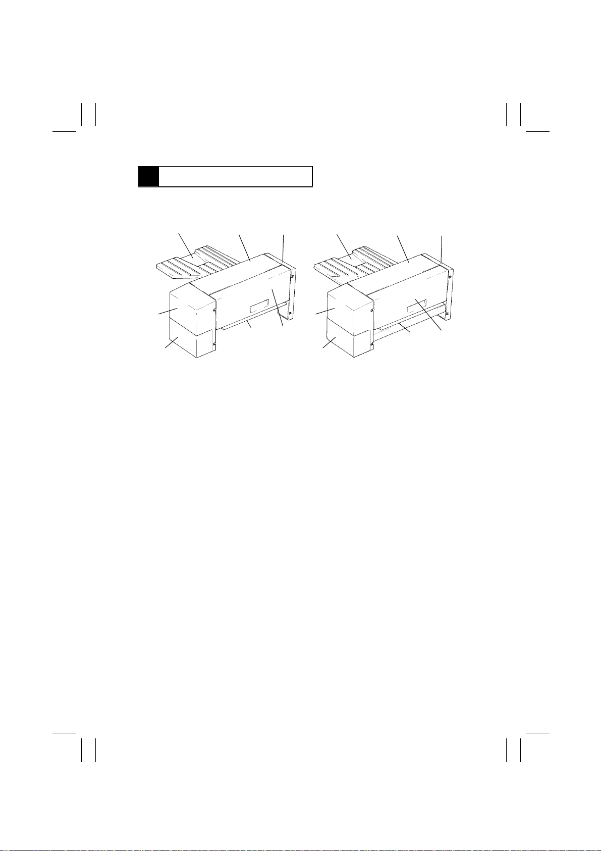
2 PART IDENTIFICATION
<Job Tray> <Shift Tray>
1
7 7
6
1. Exit Tray
2. Top Cover
3. Rear Cover
23
5
4
4602M001AA
1
6
4. Paper Misfeed Removal Door
5. Exit Path Switching Plate
6. Lower Front Cover
7. Front Cover
23
5
4
4491M001AA
M-2
Page 6
FrameMaker Ver.5.5(PC) JS-200/OT-100 OPTION FOR Di350
98.12.18
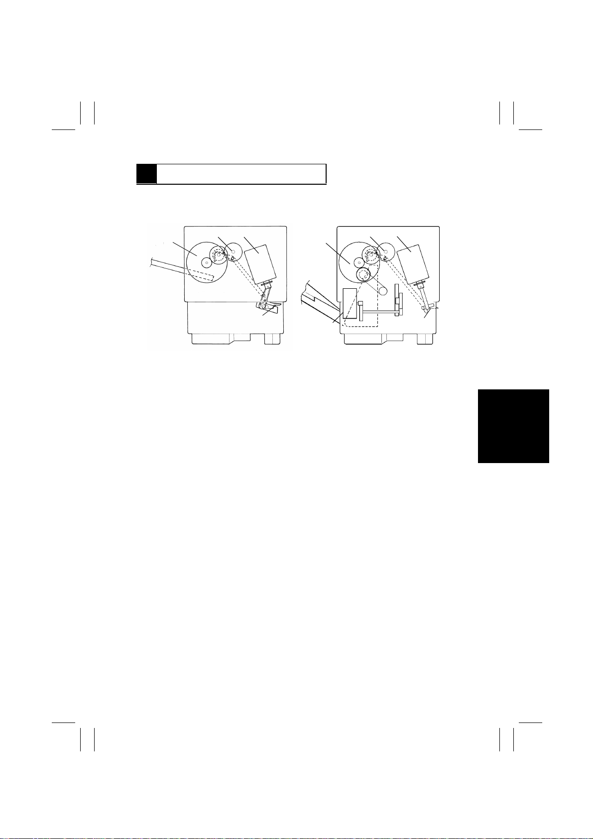
3 CROSS-SECTIONAL VIEW
<Job Tray> <Shift Tray>
1
23
1
3
2
1. Transport Motor M1
2. Paper Exit Roller
3. Path Switching Solenoid SL1
4
4602M002AA
5
4. Exit Path Switching Plate
5. Shift Motor M2 (Shift Tray only)
4
4491M002AA
M-3
Page 7
FrameMaker Ver.5.5(PC) JS-200/OT-100 OPTION FOR Di350
98.12.18
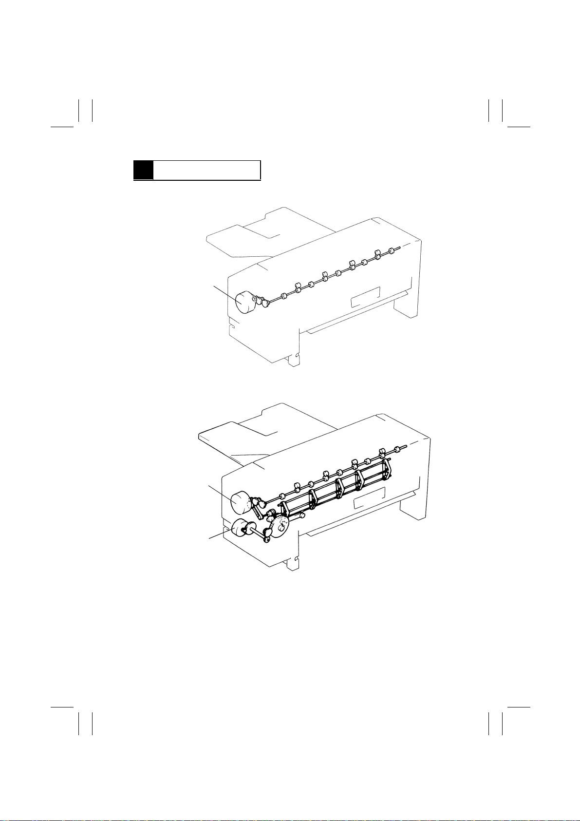
4 DRIVE SYSTEM
<Job Tray>
Transport Motor M1
4602M003AA
<Shift Tray>
Transport Motor M1
Shift Motor M2
4491M003AA
M-4
Page 8
FrameMaker Ver.5.5(PC) JS-200/OT-100 OPTION FOR Di350
98.12.18
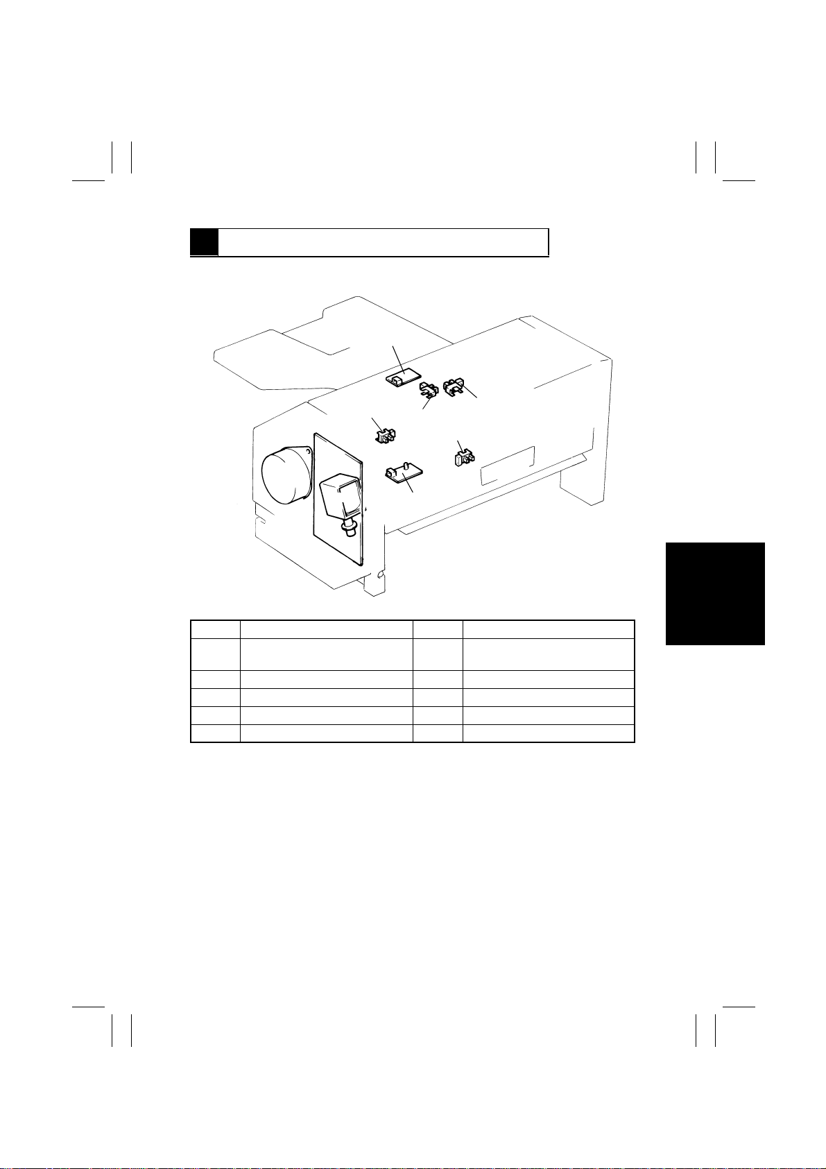
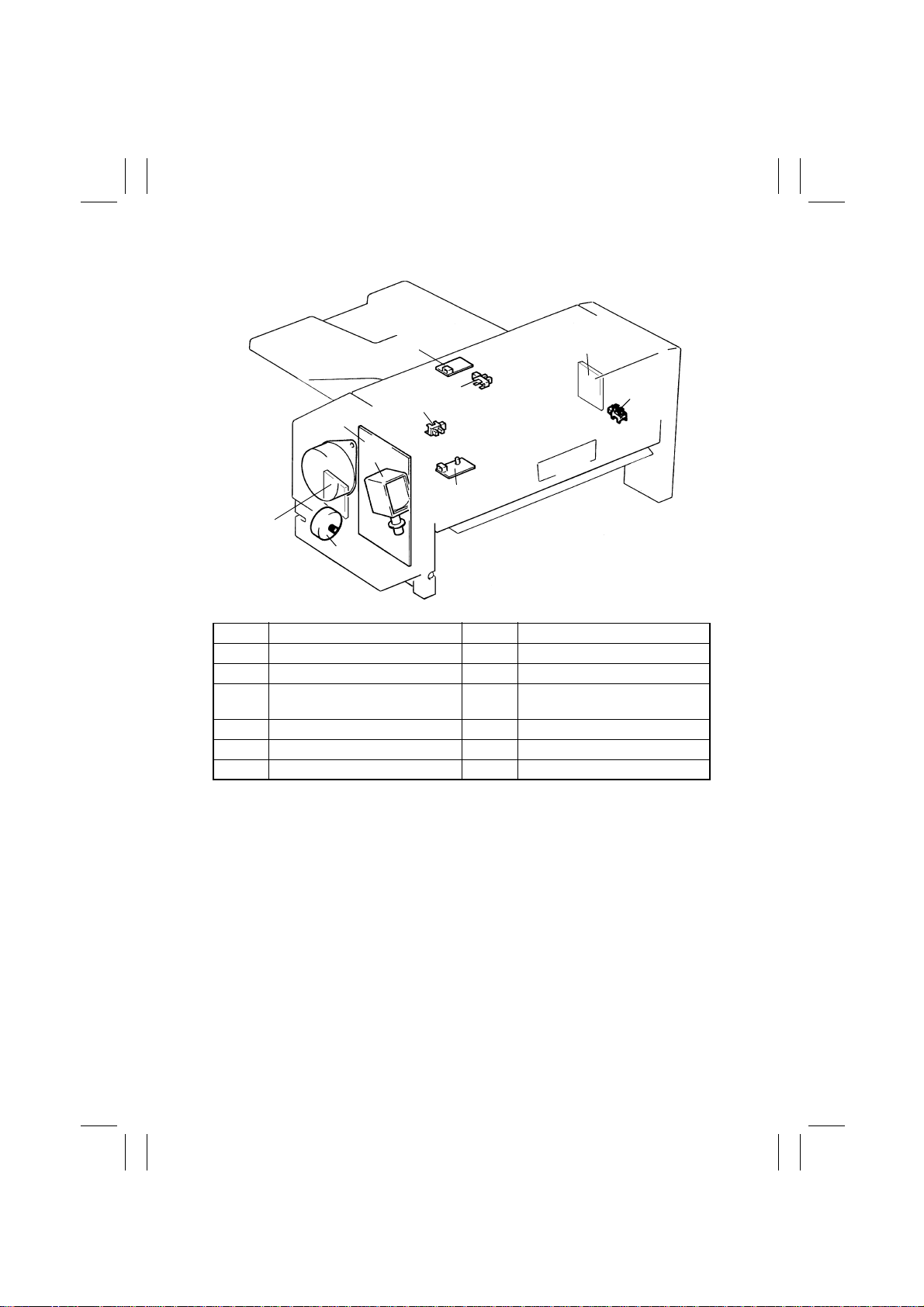
5 ELECTRICAL COMPONENTS LAYOUT
<Job Tray>
PWB-B1
PC1
PWB-A
M1
SL1
Symbol Name Symbol Name
PWB-A Main Board PC1 Paper Misfeed Removal Door Set
PWB-B1 Upper Empty Sensor PQ Board PC2 Upper Full Detecting Sensor
PWB-C1 Upper Empty Sensor LED Board PC3 Upper Exit Sensor
M1 Transport Motor PC5 Lower Full Detecting Sensor
SL1 Path Switching Solenoid
PC3
PWB-C1
PC2
PC5
4602M004AB
Sensor
M-5
Page 9
FrameMaker Ver.5.5(PC) JS-200/OT-100 OPTION FOR Di350
98.12.18
<Shift Tray>
PWB-B1
PC3
PWB-A
M1
PWB-B2
M2
Symbol Name Symbol Name
PWB-A Main Board M2 Shift Motor
PWB-B1 Upper Empty Sensor PQ Board SL1 Path Switching Solenoid
PWB-C1 Upper Empty Sensor LED Board PC1 Paper Misfeed Removal Door Set
PWB-B2 Upper Full Sensor PQ Board PC3 Upper Exit Sensor
PWB-C2 Upper Full Sensor LED Board PC4 Shift Home Sensor
M1 Transport Motor
PC1
SL1
PWB-C1
Sensor
PWB-C2
PC4
4491M004AC
M-6
Page 10
FrameMaker Ver.5.5(PC) JS-200/OT-100 OPTION FOR Di350
98.12.18
6 OPERATION OF EACH MECHANISM
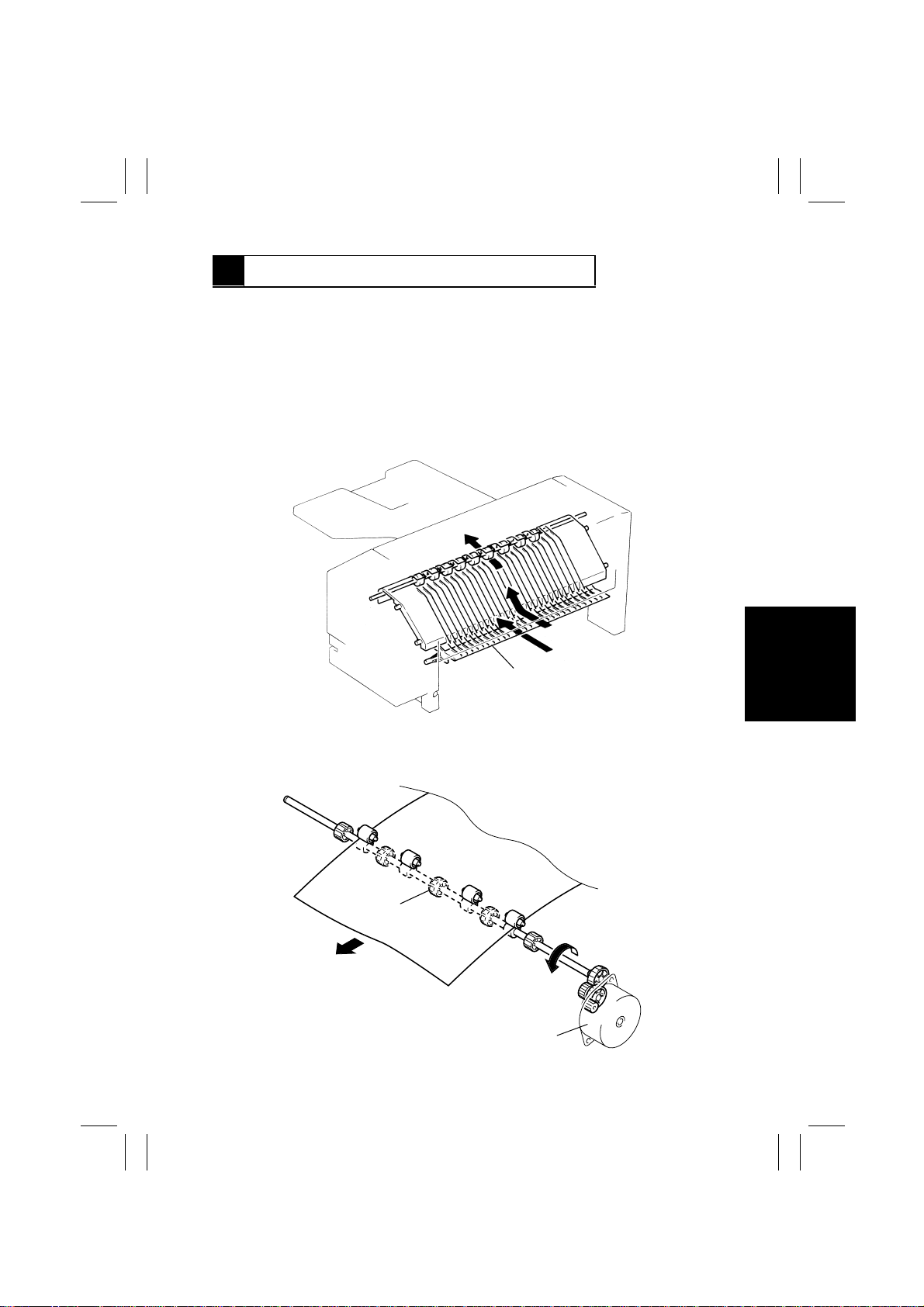
6-1. Paper Transport Mechanism
(1) Paper Transport Path
A sheet of paper fed out of the copier by the Paper Exit Roller/Rolls of the copier is fed
through, and out of, this unit by the unit’s Paper Exit Roller onto the unit’s Exit Tray.
Since this unit is mounted directly on top of the copier, Section over the copier Exit Tray, it
serves as an upper exit tray. The tray into which paper is fed out is selected depending on
the copying mode.
Exit Path Switching Plate
(2) Paper Exit Roller Drive
The Paper Exit Roller is driven by Transport Motor.
Paper Exit Roller
Transport Motor M1
M-7
4602M005AA
4602M006AB
Page 11

FrameMaker Ver.5.5(PC) JS-200/OT-100 OPTION FOR Di350
98.12.18
(3) Control of Transport Motor
A two-phase stepping motor is used as Transport Motor. The motor is tur ned as the pulse
signals output from PJ8A-1 to 4 are applied to it. The direction of the motor rotation is
switched by changing the output sequence of these pulse signals.
PJ8A
1LLHH
2HHLL
3LHHL
4HLLH
Forward Rotation
Transport Motor is energized when the paper fed through the copier during a copy cycle
activates the Paper Exit Sensor of the copier if the Upper Exit Tray is selected as the exit
port.
It is deenergized if the Paper Exit Sensor of the copier is not activated even after the lapse
of 1 sec. after Upper Exit Sensor has been deactivated.
1234
Step
M-8
Page 12
FrameMaker Ver.5.5(PC) JS-200/OT-100 OPTION FOR Di350
98.12.18
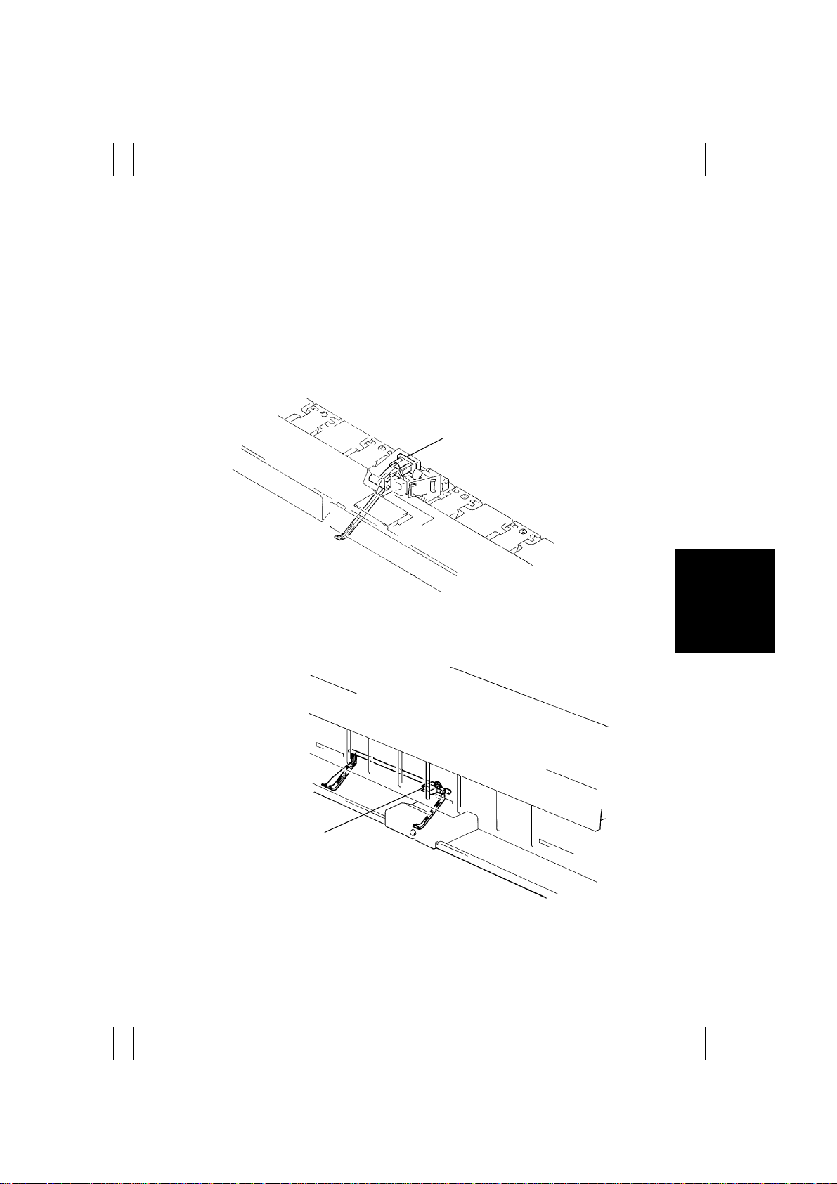
6-2. Full-of-Paper Detecting Mechanism
(1) Job Tray
•
Paper is fed into the Upper Exit Tray or Lower Exit Tray depending on the copy mode.
The paper being fed into the tray operates the actuator, which unblocks and blocks the
Upper or Lower Full Detecting Sensor to allow the system to detect a full-of-paper condi-
tion.
(Upper Exit Tray)
A full-of-paper condition is detected when the Upper Full Detecting Sensor remains
unblocked for a continuous, given period time.
Upper Full Detecting Sensor PC2
4602M007AA
(Lower Exit Tray)
A full-of-paper condition is detected when the Lower Full Detecting Sensor remains
unblocked for a continuous, given period time.
Lower Full Detecting Sensor PC5
4602M008AB
M-9
Page 13
FrameMaker Ver.5.5(PC) JS-200/OT-100 OPTION FOR Di350
98.12.18
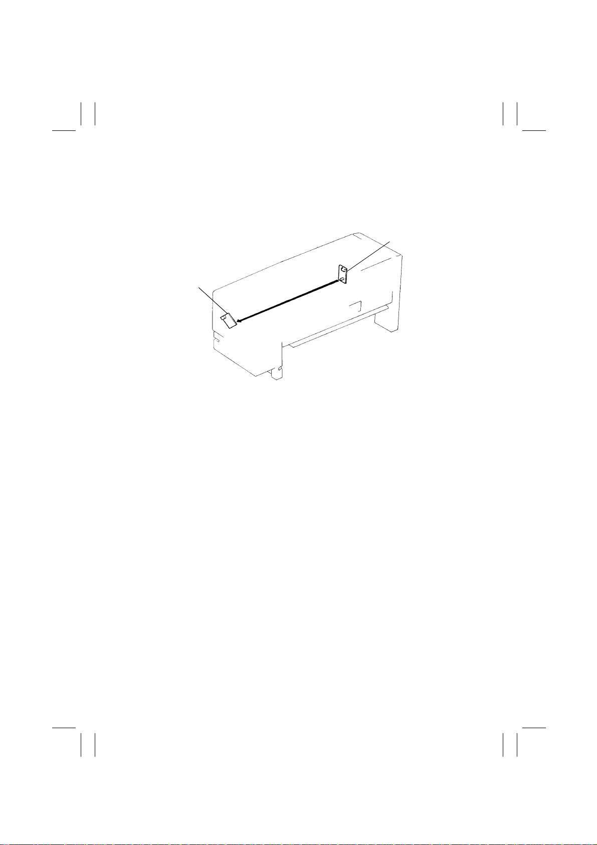
(2) Shift Tray
In the Shift Tray, a photointerruptor (PWB-B2, -C2) is used. When light from the PWB-C2
LED is blocked by a sheet of paper being fed out onto the tray, a full-of-paper condition is
detected.
Upper Full Sensor
LED Board PWB-C2
Upper Full Sensor
PQ Board PWB-B2
4602M008AA
M-10
Page 14
FrameMaker Ver.5.5(PC) JS-200/OT-100 OPTION FOR Di350
98.12.18
6-3. Exit Path Switching Mechanism
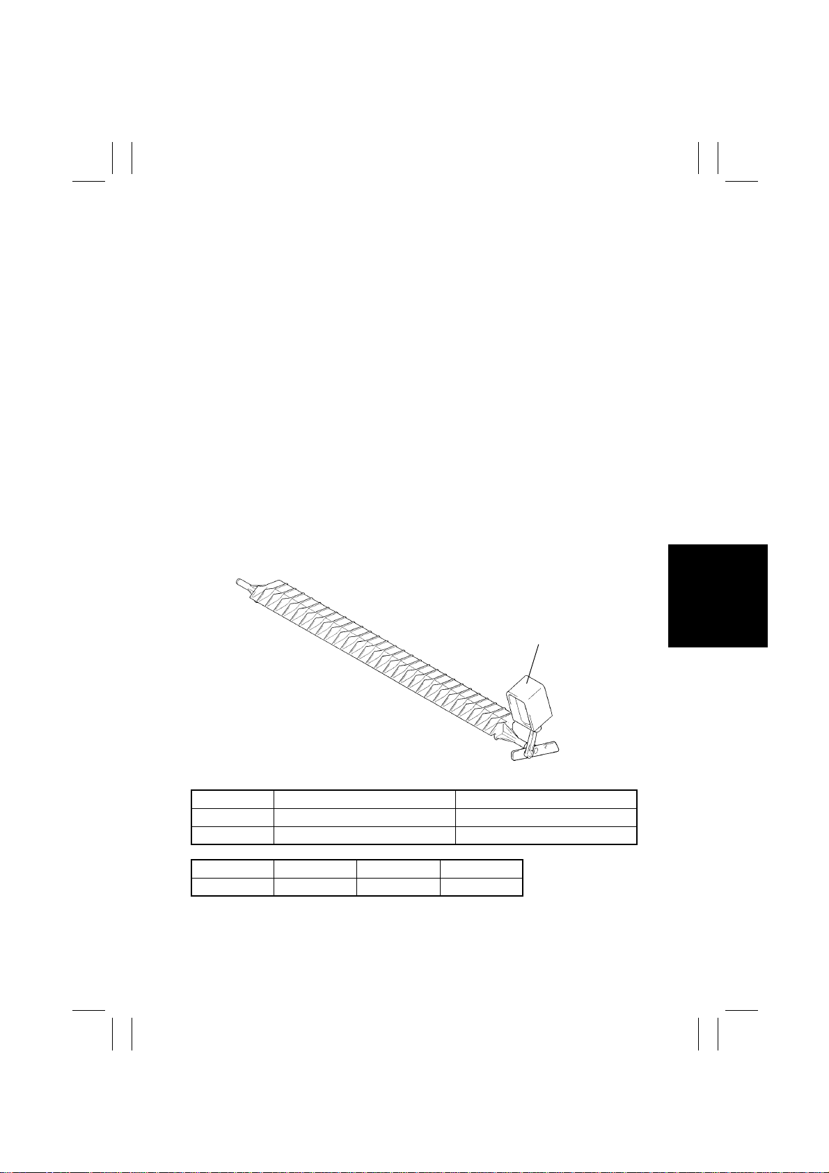
The paper path is selected by energizing or deenergizing Path Switching Solenoid SL1,
which results in the Exit Path Switching Plate being swung down or up.
(1) Job Tray
The paper exit tray (Upper or Lower Exit Tray) is selected according to the setting made on
the copier.
When the Lower Exit Tray is selected, the Path Switching Solenoid is deenergized a given
period of time after the Paper Exit Sensor of the copier has been blocked, thereby feeding
the paper into the Lower Exit Tray.
In the 2-sided copy mode, the paper fed into this unit is reversed (switchback) and fed back
towards the Duplex Unit. (The Path Switching Solenoid is deenergized if the Paper Exit
Sensor of the copier is not blocked within a given period of time after the switchback operation has been started.)
(2) Shift Tray
In the 2-sided copy mode, if the length of the paper being fed into this unit exceeds 150
mm, the Path Switching Solenoid is energized after a given period of time after the Paper
Exit Sensor of the copier has been blocked to reverse the paper under the Exit Tray and
feed it back into the Duplex Unit.
If the length of the paper being fed into the unit is 150 mm or less, the Path Switching Solenoid is deenergized after a given period of time after the Paper Exit Sensor of the copier
has been blocked to transport the paper into the Exit Tray.
Path Switching Solenoid SL1
4602M009AA
SL1 Energized SL1 Deenergized
Job Tray Paper fed into the Upper Exit Tray Paper fed into the Low er Exit Tray
Shift Tray For switchback to Duplex Unit When feeding paper out
Control Signal ON OFF
SL1 PJ6A-2 L H
M-11
Page 15
FrameMaker Ver.5.5(PC) JS-200/OT-100 OPTION FOR Di350
98.12.18
6-4. Initial Operation
The Transport Motor is energized at the same time when predrive of the copier is started
(Job Tray/Shift Tray).
The unit carries out the Shift T ray home position detection sequence when the Power
Switch of the copier is turned ON or when the Paper Misf eed Remo val Door is opened and
closed after a paper misfeed has been cleared (Shift Tray only).
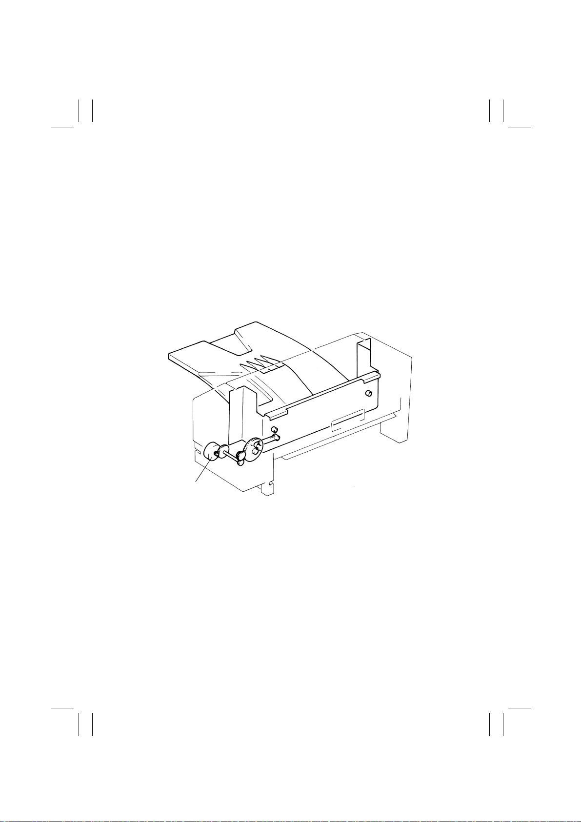
(1) Shift Tray Home Position Detection
The unit determines that the Shift Tray is at its home position when the Shift Home Sensor
is blocked by the light blocking plate.
(If the Shift Tray is at its home position)
The Shift Motor is energized (forward or backward rotation) so that the Shift Home Sensor
is unblocked, then blocked again.
(If the Shift Tray is out of its home position)
The Shift Motor is energized until the Shift Home Sensor is blocked.
Shift Motor M2
4491M005AA
M-12
Page 16
FrameMaker Ver.5.5(PC) JS-200/OT-100 OPTION FOR Di350
98.12.18
6-5. Paper Misfeed Removal Door Set Detection
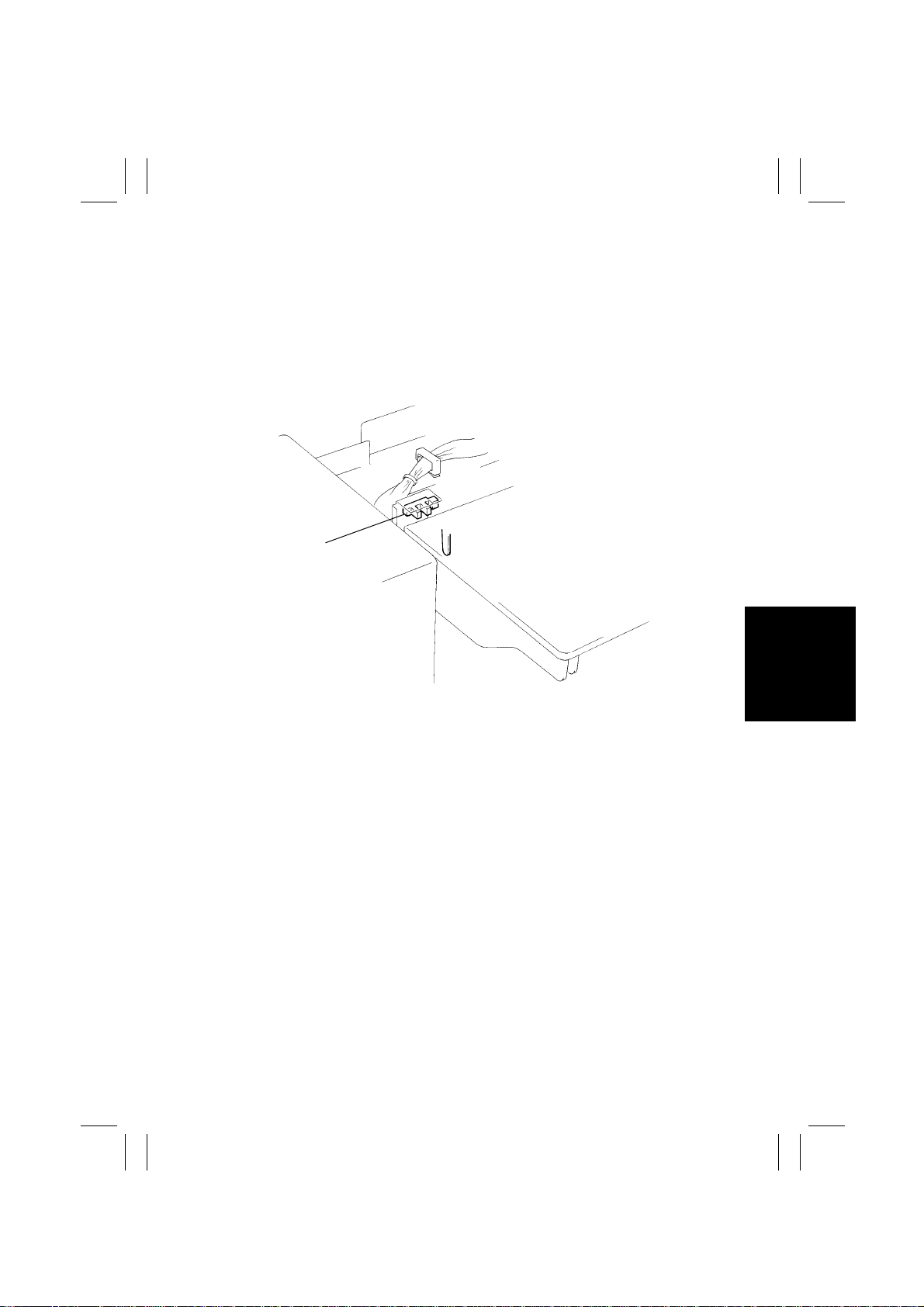
The Paper Misfeed Removal Door is detected at its closed position by the Paper Misfeed
Removal Door Set Sensor. The unit determines that the door is left open if the sensor
remains unblocked for a given period of time and that it is closed if the sensor remains
blocked for a given period of time.
If the sensor is unblocked, a closure failure warning is given on the copier control panel and
the copier inhibits the initiation of a new copy cycle.
Paper Misfeed Removal
Door Set Sensor PC1
M-13
4602M010AA
Page 17

FrameMaker Ver.5.5(PC) JS-200/OT-100 OPTION FOR Di350
98.12.18
DIS/REASSEMBLY,
ADJUSTMENT
Precautions for Disassembly, Reassembly, and Adjustment
•
Before attempting to disassemble the unit, alwa ys make sure that no power is being sup-
plied from the copier (by unplugging the power connector from the copier).
•
While power is being supplied to the unit, do not attempt to remove/install the print jacks
from/to the PWBs or unplug/plug in the connectors.
•
If the unit is run with its covers removed, use care not to allow your clothing to be caught
in revolving parts.
•
The basic rule is do not run the unit with any of its parts removed.
•
A toothed washer is used with the screw that secures the ground wire to ensure positive
conduction. Do not forget to include this washer at reassembly.
•
To reassemble the unit, reverse the order of disassembly unless otherwise specified.
•
Do not attempt to remove or loosen the screws to which red paint has been applied.
Page 18
FrameMaker Ver.5.5(PC) JS-200/OT-100 OPTION FOR Di350
98.12.18
1 DISASSEMBLY
1-1. PM List
PM Part Name Cleaning (K) Replacement (K) Part No. Qty Ref. Page
Paper Exit Roller 300 - 4491-3101-02 1 D-2
1. The contents of the PM parts list are subject to change without notice.
2. K = 1,000 copies
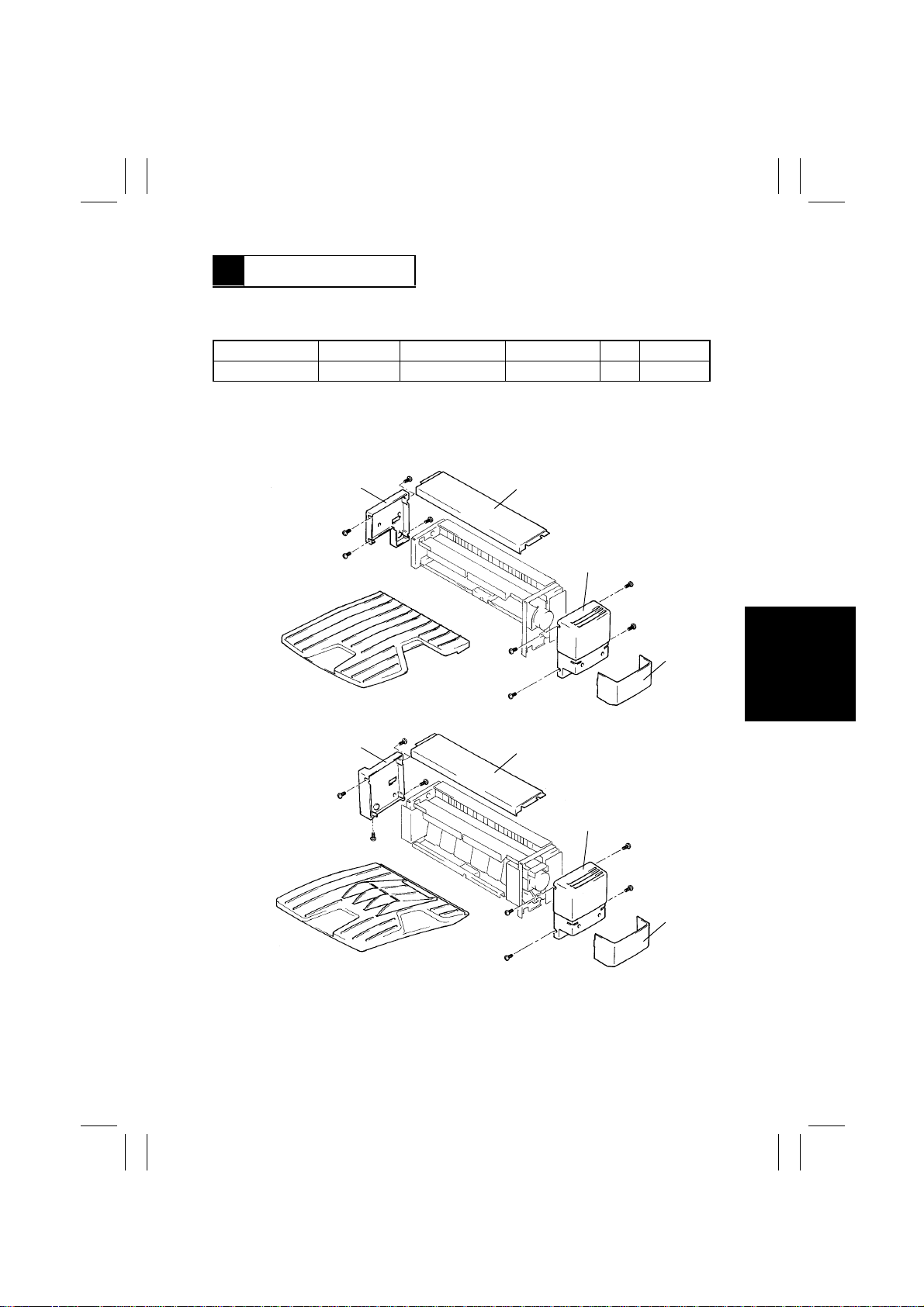
1-2. Removal of the Exterior Covers
Job Tray
1
2
3
4
4602M011AA
Shift Tray
1. Rear Cover: Loosen four screws and slide the cover toward to the rear.
2. Top Cover: Remove the Front and Rear Covers and lift the cover upward.
3. Front Cov er: Remov e the Lower Front Cover, loosen four screws, and slide the cover to
the front.
4. Lower Front Cover: Unlock the tabs and slide the cover to the front.
1
2
3
4
4491M006AA
D-1
Page 19
FrameMaker Ver.5.5(PC) JS-200/OT-100 OPTION FOR Di350
98.12.18
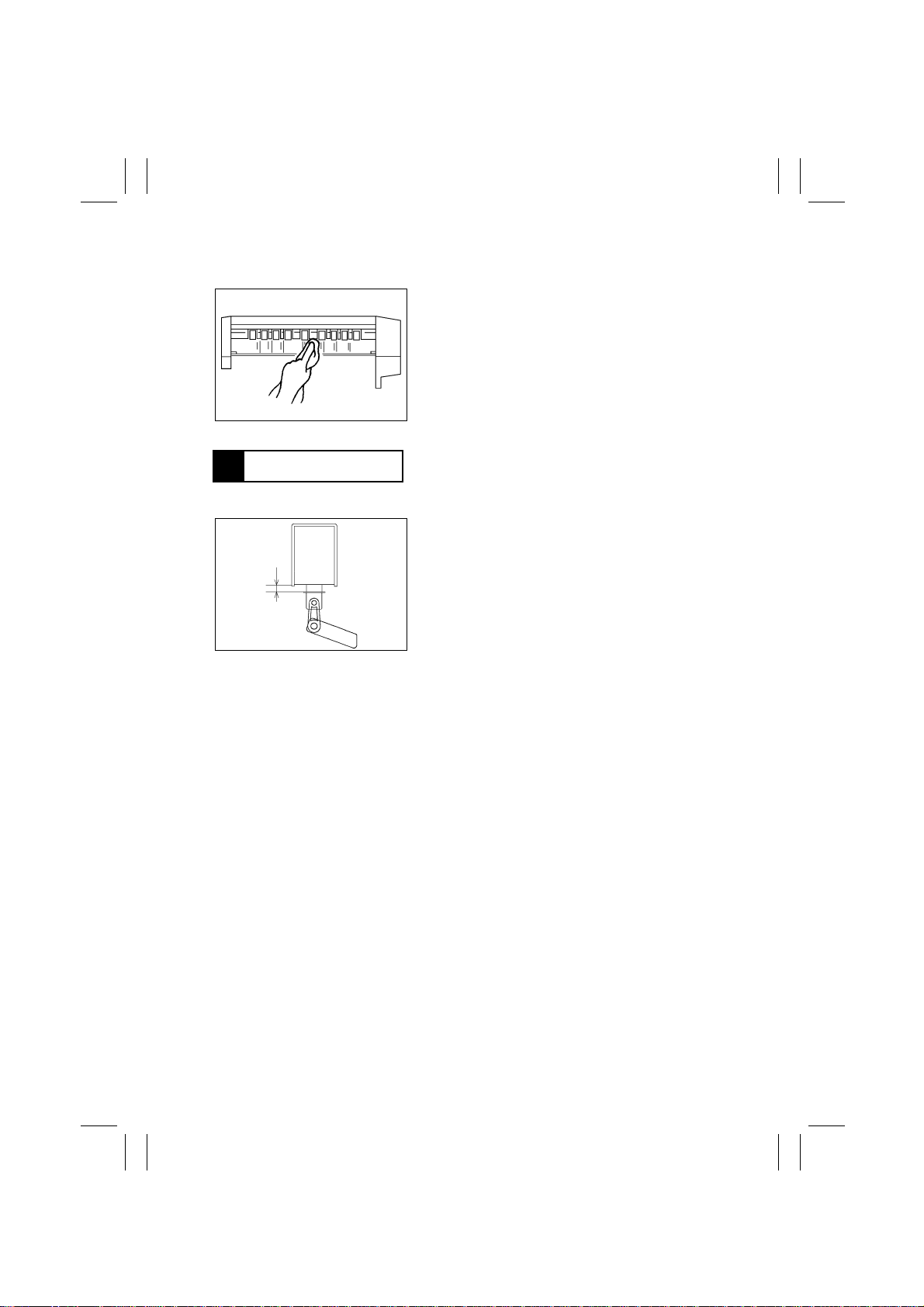
1-3. Cleaning of the Paper Exit Roller
Wipe the surface of the Paper Exit Roller clean of dirt
with a cloth dampened with alcohol.
4602D002AA
2 ADJUSTMENT
Path Switching Solenoid Stroke Adjustment
1. Remove the Main Board.
2. Loosen the two screws that secure the solenoid
A
and adjust its position so that dimension A measures 5.2 to 4.7 mm (Job Tray) or 4.4 to 3.9 mm
(Shift Tray).
4602D001AA
D-2
Page 20

FrameMaker Ver.5.5(PC) JS-200/OT-100 OPTION FOR Di350
98.12.18
TROUBLESHOOTING
Page 21
FrameMaker Ver.5.5(PC) JS-200/OT-100 OPTION FOR Di350
98.12.18
P APER MISFEED DETECT ION AND TROUBLESHOO TING PROCEDURES
1
1-1. Misfeed Detection
A paper misfeed is detected under any of the following conditions, causing a misfeed display to be given on the copier control panel.
Type Detection Timing
Transport
misfeed
Paper left The Upper Exit Sensor is blocked when the Power Switch is turned ON or
Exit misfeed The Upper Exit Sensor is not unblocked within a given period of time after
The Upper Exit Sensor is not block ed within a giv en period of time after t he
Paper Exit Sensor of the copier has been blocked.
a paper misfeed is reset.
the Paper Exit Sensor of the copier has been unblocked.
1-2. Misfeed Troubleshooting Procedures
Step Check Item
1 Does the paper being used meet
product specifications?
2 Is the paper curled, waved, or damp? YES Change the paper. Instruct the user
3 Is the Transport Guide Plate dirty? YES Remove foreign matter and clean the
4 Is the Transport Roller deformed or
worn?
5 Does the Tr ansport Motor operate
properly?
6 Does the actuator of the Upper Exit
Sensor operate properly?
7 Is the Upper Exit Sensor output sig-
nal properly applied to the Main
Board?
Result
NO Instruct the user to use paper that
meets product specifications.
in how to store the paper.
guide plate.
YES Change the Transport Roller.
NO Check the wiring between the Main
Board and Transport Motor and, if it
is intact, change the motor.
NO Check the position of the Upper Exit
Sensor installation and check the
actuator for deformation and contamination.
YES Change the Main Board.
NO Check the wiring between the Main
Board and Upper Exit Sensor and, if
it is intact, change the sensor.
Action
T-1
Page 22

FrameMaker Ver.5.5(PC) JS-200/OT-100 OPTION FOR Di350
98.12.18
MALFUNCTION DETECTION AND TROUBLESHOO TING PR OCEDURES
2
2-1. Malfunction Detection (Shift Tray only)
A malfunction is detected under the following condition, causing the corresponding malfunction code to be displayed on the copier control panel.
Malfunction
Code
C0B80 Shift Tray
Malfunction Detail Detection Timing
shift motion failure
(When moving from home to shift position)
The Shift Home Sensor is blocked after a given
period of time after the Shift Motor has been
energized (at which timing the motor is deenergized).
(When moving from shift to home position)
The Shift Home Sensor is not blocked even after
the lapse of a given period of time after the Shift
Motor has been energized.
2-2. Malfunction Troubleshooting Procedures
Step Check Item
1 Does the Shift T ra y mov e in the ini tial
operation?
2 Does the Shift Tray slide smoothly
when the gear is turned manually
with the Shift Motor removed?
3 Is an output signal being sent from
the Main Board to Shift Motor?
4 Are the Shift Home Sensor and its
light blocking plate dirty?
5 Is the Shift Home Sensor output sig-
nal properly applied to the Main
Board?
Result
YES Check step 4.
NO Check for contamination and
improper installation.
YES Check the wiring between the Main
Board and Shift Motor and, if it is
intact, change the motor.
NO Change the Main Board.
YES Remove foreign matter or clean.
YES Change the Main Board.
NO Check the wiring between the Main
Board and Shift Home Sensor and, if
it is intact, change the sensor.
Action
T-2
Page 23
3568724
A
B
C
D
91
A
B
C
D
E
F
G
H
I
DWG.NO.
TITLE
MODEL
VOLTAGE
EFFECTIVE
MACHINE NO.
DATE ISSUED
4491-C001-0A
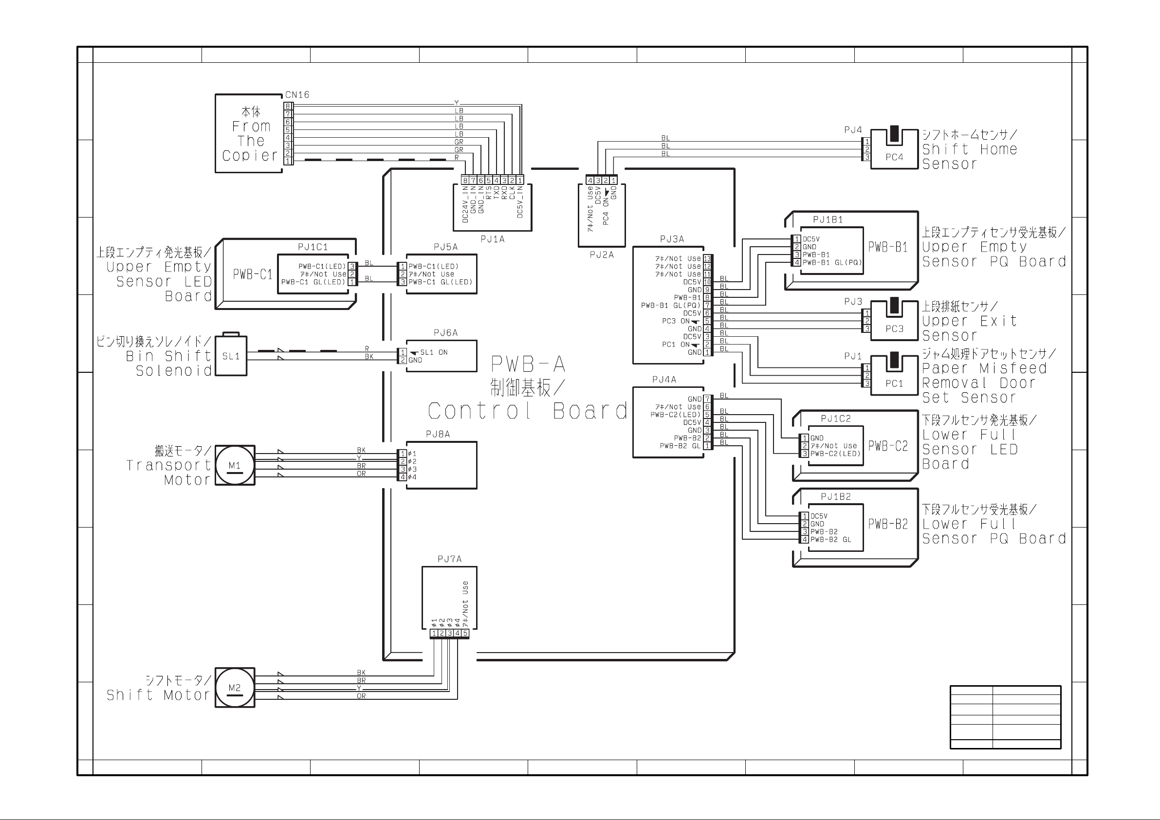
WIRING DIAGRAM
OT-100
From the copier
XX0201 AND ONWARD
Dec.1998
E
F
G
H
I
12345678
9
Page 24
3568724
A
B
C
D
91
A
B
C
D
E
F
G
H
I
DWG.NO.
TITLE
MODEL
VOLTAGE
EFFECTIVE
MACHINE NO.
DATE ISSUED
4491-C201-0A
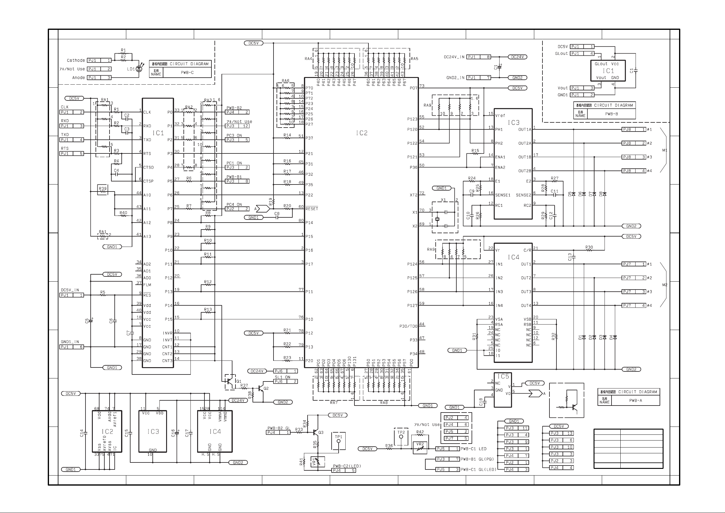
CIRCUIT DIAGRAM PWB-A,B,C
OT-100
From the copier
XX0201 AND ONWARD
Dec.1998
E
F
G
H
I
12345678
9
Page 25
3568724
A
B
C
D
91
A
B
C
D
E
F
G
H
I
DWG.NO.
TITLE
MODEL
VOLTAGE
EFFECTIVE
MACHINE NO.
DATE ISSUED
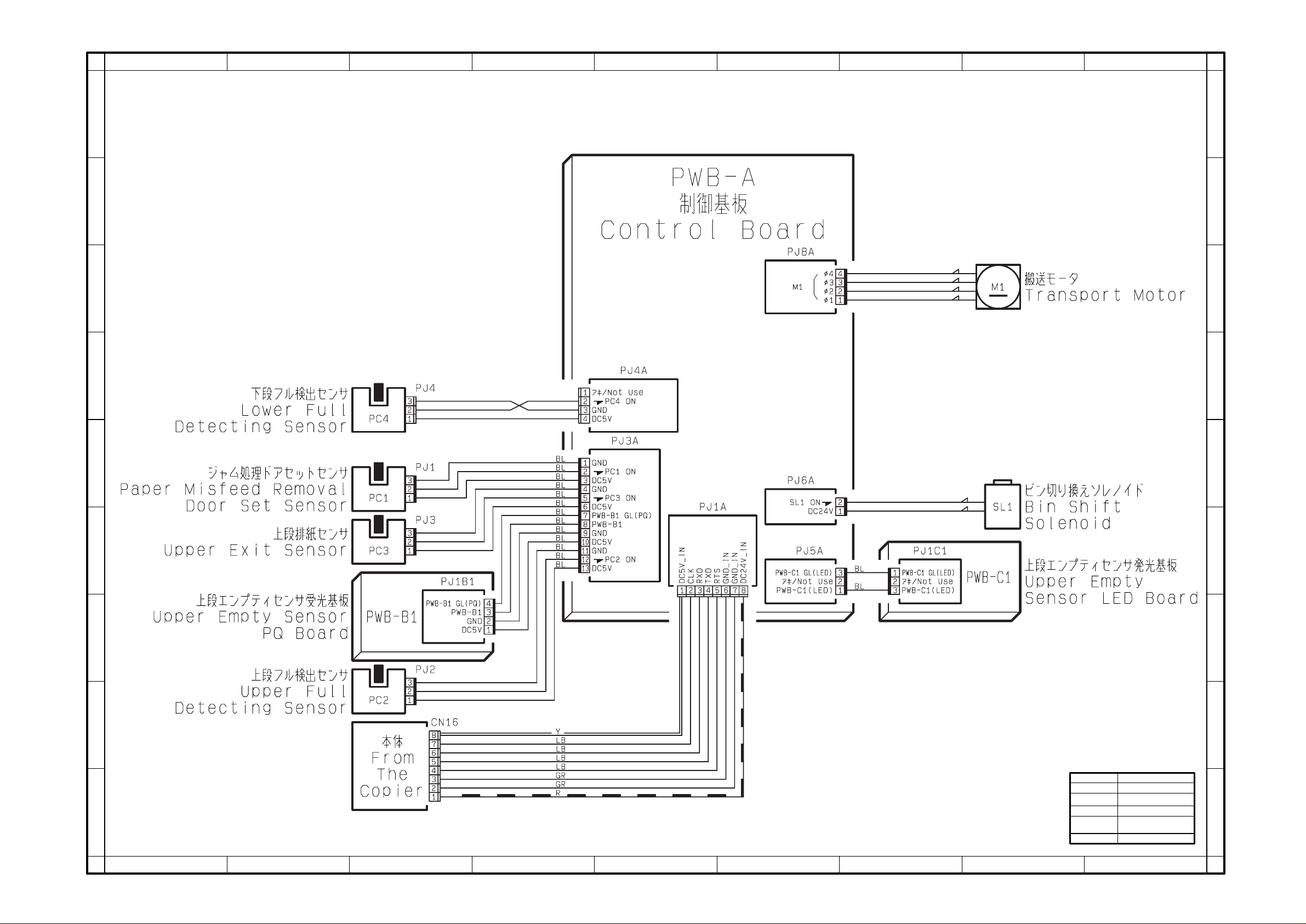
4602-C001-0A
WIRING DIAGRAM
JS-200
From the copier
XX0201 AND ONWARD
Dec.1998
E
F
G
H
I
12345678
9
Page 26
A
B
C
D
3568724
91
A
B
C
D
E
F
G
H
I
DWG.NO.
TITLE
MODEL
VOLTAGE
EFFECTIVE
MACHINE NO.
DATE ISSUED
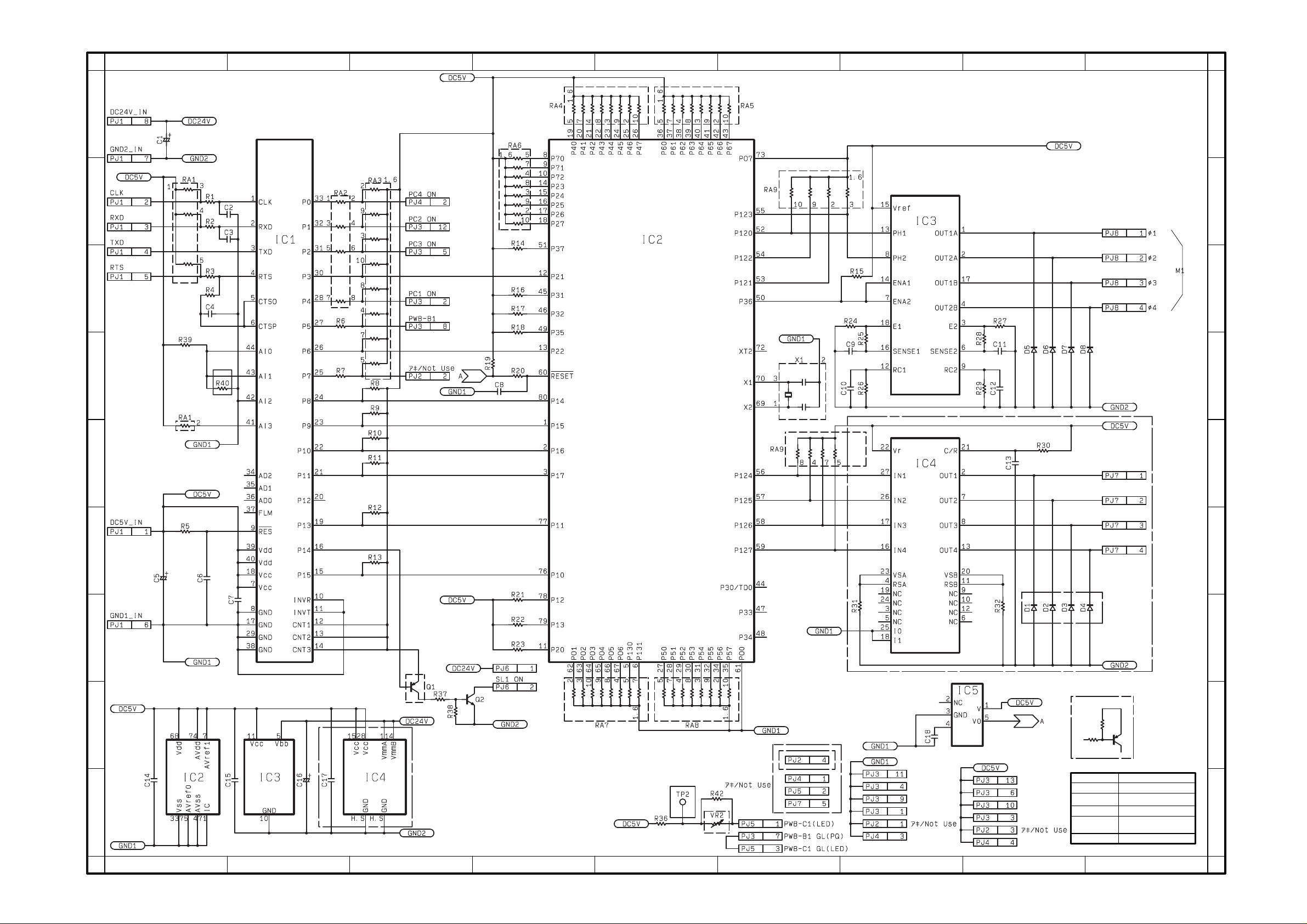
4602-C201-0A
CIRCUIT DIAGRAM PWB-A
JS-200
From the copier
XX0201 AND ONWARD
Dec.1998
E
F
G
H
I
12345678
9
 Loading...