

Page 1
KONICA MINOLTA FAX2900/FAX3900
User’s Guide
Page 2

Contents
Contents
1 Introduction
1.1 We Want You to Be a Satisfied Customer ..................................1-2
For U.S.A. Users
FCC Part 15-Radio Frequency Devices .....................................1-2
For Canada Users
Interference-Causing Equipment Standard (ICES-003 Issue 4).1-3
For users in countries subject to Class B regulations.................1-3
For users in countries not subject to Class B regulations...........1-3
1.2 Safety Information.........................................................................1-4
47 CFR - Telecommunication Devices .....................................1-11
Warning For Setting Of Header And Footer .............................1-12
IC CS-03-Telecommunication Devices.....................................1-12
Laser Safety .............................................................................1-13
Internal Laser Radiation ...........................................................1-13
CDRH Regulation.....................................................................1-14
For European Users .................................................................1-15
For Denmark Users ..................................................................1-15
For Finland, Sweden Users......................................................1-15
For Norway Users.....................................................................1-17
Laser Safety Label....................................................................1-17
Ozone Release.........................................................................1-18
Acoustic Noise..........................................................................1-18
Notice for Ni-MH Batteries........................................................1-18
1.3 Energy Star® ...............................................................................1-19
What is an ENERGY STAR® Product?....................................1-19
1.4 Explanation of Manual Conventions .........................................1-20
1.5 Explanation of Basic Concepts and Symbols..........................1-21
Paper Feeding..........................................................................1-21
“Width” and “Length”.................................................................1-22
Paper Orientation .....................................................................1-22
2 Precautions
2.1 Installation Precautions................................................................2-2
Installation Site ...........................................................................2-2
Power Source.............................................................................2-2
Space Requirements..................................................................2-3
2.2 Operation Precautions..................................................................2-4
i
Page 3

Operating Environment.............................................................. 2-4
Proper Use................................................................................. 2-4
Transporting the Machine ..........................................................2-5
Care of Machine Supplies.......................................................... 2-5
2.3 Legal Restrictions on Copying.................................................... 2-6
3 Before Making Copies or Faxing
3.1 Available Features........................................................................ 3-2
3.2 Components and Their Functions .............................................. 3-3
3.3 Parts Names and Their Functions .............................................. 3-4
Main Unit.................................................................................... 3-4
Inside the Machine..................................................................... 3-5
Adjusting the Angle of the Copy Tray ........................................ 3-6
3.4 Control Panel ................................................................................ 3-8
Names of Control Panel Parts and Their Functions................... 3-8
Display Indications................................................................... 3-12
3.5 Turning the Machine On/Off Initial Mode ................................. 3-14
Turning the Machine On/Off..................................................... 3-14
To turn on the machine: ........................................................... 3-14
To turn off the machine: ........................................................... 3-14
When the Machine is Turned On ............................................. 3-14
Default Settings........................................................................ 3-15
3.6 Useful Functions ........................................................................ 3-16
Panel Resetting........................................................................3-16
Auto Panel Reset..................................................................... 3-16
Energy Save Mode ..................................................................3-16
Auto Print Start......................................................................... 3-17
Auto Tray Switching ................................................................ 3-17
3.7 Entering Text............................................................................... 3-18
Changing Input Mode............................................................... 3-18
Inputting Example .................................................................... 3-19
3.8 Copy Paper.................................................................................. 3-21
Paper Specifications ................................................................ 3-21
Precautions for Loading Paper ................................................ 3-21
Unsuitable Paper ..................................................................... 3-22
Loading Paper.......................................................................... 3-23
Loading Paper into Tray1......................................................... 3-25
Loading Paper into the Bypass Tray........................................ 3-27
Loading Paper into Tray2 (option) ........................................... 3-28
3.9 Loading Originals ....................................................................... 3-29
Loading Originals in the Auto Document Feeder..................... 3-29
Contents
ii
Page 4

Contents
Specific Types of Originals .......................................................3-29
Precautions for Loading Paper Into the Auto Document
Feeder ......................................................................................3-29
Loading Originals into the Auto Document Feeder...................3-30
3.10 Checking the Machine Status....................................................3-31
Checking the “TOTAL PAGE” Counts......................................3-32
Checking the “TX/RX RESULT” ...............................................3-33
To output a report/list................................................................3-34
TX Result Report......................................................................3-35
RX Result Report......................................................................3-35
Activity Report ..........................................................................3-35
Memory Data List .....................................................................3-35
Memory Image Print .................................................................3-36
One-Touch List.........................................................................3-36
Speed Dial List .........................................................................3-36
Key Setting List.........................................................................3-36
Machine Status.........................................................................3-36
Configuration Page...................................................................3-36
Relay Box List (Available only with FAX3900)..........................3-36
3.11 Print Area.....................................................................................3-37
4 Making Copies
4.1 Making a Basic Copy ....................................................................4-2
4.2 Selecting the Paper.......................................................................4-4
Manual Paper Selection .............................................................4-4
Selecting Manually Fed Paper....................................................4-4
Manually Selecting the Paper Size.............................................4-4
Specifying the Size and Type on the Manual Bypass Tray ........4-5
4.3 Specifying the Zoom Ratio...........................................................4-9
Zoom Ratio Settings...................................................................4-9
Setting the Zoom Ratio.............................................................4-10
4.4 Adjusting the Image Density......................................................4-11
Image Density Setting ..............................................................4-11
Setting the Image Density ........................................................4-11
4.5 Making 2in1 Copies (Available only with FAX3900).................4-13
Specifying Settings for 2in1 Copies..........................................4-13
4.6 Finishing Copies .........................................................................4-14
Specifying Sorting.....................................................................4-15
5Faxing
5.1 Dialing ............................................................................................5-2
iii
Page 5

To fax by entering the fax number directly using the 10-Key
Pad............................................................................................. 5-2
To fax using one-touch dialing ................................................... 5-3
To fax using speed dialing .........................................................5-5
To fax using group dialing.......................................................... 5-6
To fax using chain dialing .......................................................... 5-7
To fax using program dialing (Available only with FAX3900)..... 5-8
To fax using the phone book......................................................5-9
To search the phone book .......................................................5-10
To redial the last recipient called ............................................. 5-11
5.2 Transmission Settings ............................................................... 5-12
Adjusting the Fax Resolution ................................................... 5-12
To specify the resolution.......................................................... 5-12
5.3 Basic Faxing ............................................................................... 5-13
To fax using the Auto Document Feeder ................................. 5-13
If the Memory Becomes Full While Scanning Fax Documents 5-14
5.4 Checking Transmission Results ............................................... 5-15
To check the transmission result ............................................. 5-15
6 Fax Transmission/Reception Methods
6.1 Transmission Methods ................................................................ 6-2
Memory Transmission................................................................6-2
To specify Memory TX ............................................................... 6-2
Direct Transmission ................................................................... 6-3
Manual Transmission................................................................. 6-4
To send a fax manually.............................................................. 6-5
Batch Transmission ................................................................... 6-6
To fax using batch transmission ................................................ 6-6
Broadcast Transmission ............................................................ 6-7
To fax using broadcast transmission ......................................... 6-7
Timer Transmission ................................................................. 6-10
To fax using timer transmission ...............................................6-11
Mailbox Transmission .............................................................. 6-12
To fax using mailbox transmission........................................... 6-12
Relay Initiation Transmission ................................................... 6-14
To fax using relay initiation transmission ................................. 6-14
Relay Broadcast Transmission (Available only with FAX3900) 6-16
Polling Transmission................................................................ 6-17
To set up polling transmission ................................................. 6-17
To delete a document from the polling transmission setup...... 6-19
Canceling (Deleting) a Document Queued in the Memory for
Transmission............................................................................6-20
To cancel a queued document.................................................6-20
Contents
iv
Page 6

Contents
6.2 Reception Methods .....................................................................6-22
Manual Reception.....................................................................6-22
To receive a fax manually.........................................................6-22
Memory Reception ...................................................................6-22
Mailbox Reception....................................................................6-23
To retrieve a document from a mailbox....................................6-23
Polling Reception......................................................................6-24
To receive a fax using polling reception ...................................6-24
6.3 Using F codes..............................................................................6-26
Using Mailboxes .......................................................................6-27
Specifying F codes ...................................................................6-28
When sending faxes.................................................................6-28
Programming F codes ..............................................................6-28
7 Using the Utility Mode
7.1 Utility Mode....................................................................................7-2
7.2 Specifying the Machine Settings.................................................7-3
Selecting the “MACHINE SETTING” menu ................................7-4
Specifying the Setting for “AUTO PANEL RESET” ....................7-5
Specifying the Setting for “ENERGY SAVE MODE”...................7-6
Specifying the Setting for “DENSITY ”........................................7-7
Specifying the Setting for “PRINT DENSITY”.............................7-8
Specifying the Setting for “LCD CONTRAST” ............................7-9
Specifying the Setting for “BUZZER VOLUME”........................7-10
Specifying the Setting for “INITIAL MODE” ..............................7-11
7.3 Setting Up the Paper Sources....................................................7-12
Selecting the “PAPER SOURCE SETUP” menu......................7-12
Specifying the Setting for “TRAY1 PAPER” .............................7-13
Specifying the Setting for “TRAY SETTING”............................7-14
7.4 Specifying Administrative Settings (“ADMIN. MANAGEMENT”
menu) ...........................................................................................7-15
To select the “ADMIN. MANAGEMENT” menu ........................7-16
Specifying the Setting for “REMOTE MONITOR”.....................7-17
7.5 Specifying Copy Settings...........................................................7-18
Selecting the “COPY SETTING” menu.....................................7-19
Specifying the Setting for “PAPER PRIORITY”........................7-20
Specifying the Setting for “DENSITY PRIORITY”.....................7-21
Specifying the Setting for “DENSITY LEVEL (A)”.....................7-22
Specifying the Setting for “DENSITY LEVEL (M)”....................7-23
Specifying the Setting for “OUTPUT PRIORITY” .....................7-24
7.6 Setting Up the Fax Registration.................................................7-25
Selecting the “FAX REGISTRATION” menu ............................7-26
v
Page 7

Contents
Setting Up One-Touch Dialing (“ONE-TOUCH DIAL” function)7-27
To program a one-touch dial key ............................................. 7-27
To change/delete a programmed one-touch dial key............... 7-29
Specifying the Setting for “SPEED DIAL” ................................7-31
To program a speed dial number............................................. 7-31
To change/delete a programmed speed dial number.............. 7-33
Specifying the Setting for “GROUP DIAL” ...............................7-35
To program a group of fax numbers ........................................ 7-35
To change/delete a programmed group of fax numbers .......... 7-36
Specifying the Setting for “PROGRAM DIAL” (Available only with
FAX3900)................................................................................. 7-38
To set program dialing ............................................................. 7-38
To change/delete a programmed broadcast transmission....... 7-39
To change/delete a programmed timer transmission...............7-40
To change/delete a programmed mailbox transmission ..........7-41
To change/delete a programmed polling reception.................. 7-43
To change/delete a programmed relay initiation transmission. 7-44
Specifying the Setting for “BATCH TX”.................................... 7-46
To set batch transmitting..........................................................7-46
To change the batch transmission setting ............................... 7-47
To delete the batch transmission setting ................................. 7-49
Specifying the Setting for “MAILBOX”...................................... 7-50
To register a mailbox ............................................................... 7-50
To delete a mailbox..................................................................7-51
Specifying the Setting for “ RELAY BOX” (Available only with
FAX3900)................................................................................. 7-53
To register a Relay Box ........................................................... 7-53
To delete a Relay Box.............................................................. 7-54
7.7 Setting Up the Transmission..................................................... 7-55
Selecting the “TX OPERATION” menu ....................................7-55
Specifying the Setting for “SCAN CONTRAST”....................... 7-56
Specifying the Setting for “RESOLUTION” .............................. 7-56
Specifying Setting for “DEFAULT TX”...................................... 7-57
Specifying the Setting for “HEADER”....................................... 7-58
7.8 Setting Up the Reception........................................................... 7-59
Selecting the “RX OPERATION” menu.................................... 7-60
Specifying the Setting for “MEMORY RX MODE”.................... 7-61
To cancel memory reception.................................................... 7-63
Specifying the Setting for “NO.of RINGS”................................ 7-64
Specifying the Setting for “REDUCTION RX” .......................... 7-64
Specifying the Setting for “RX PRINT”.....................................7-65
Specifying the Setting for “RX MODE”.....................................7-65
Specifying the Setting for “FORWARD” ................................... 7-66
Specifying the Setting for “FOOTER”....................................... 7-67
Specifying the Setting for “SELECT TRAY” .............................7-67
vi
Page 8

Contents
Specifying the Setting for “CLOSED NETWORK”....................7-68
7.9 Setting Up the Communication..................................................7-69
Specifying the Setting for “TONE/PULSE” ...............................7-69
To specify the telephone dialing system...................................7-69
Specifying the Setting for “LINE MONITOR” ............................7-70
Specifying the Setting for “PSTN/PBX” ....................................7-71
To specify the telephone wiring system....................................7-71
7.10 Setting Up the Report Output ....................................................7-72
Selecting the “REPORTING” menu..........................................7-72
Specifying the Setting for “ACTIVITY REPORT”......................7-73
Specifying the Setting for “RESERV.REPORT” .......................7-73
Specifying the Setting for “TX RESULT REPORT” ..................7-74
Specifying the Setting for “RX RESULT REPORT”..................7-74
7.11 Specifying Initial User Data........................................................7-75
Selecting the “INITIAL USER DATA” menu..............................7-75
Specifying the Setting for “DATE&TIME”..................................7-76
Specifying the Setting for “USER FAX NO.”.............................7-77
Specifying the Setting for “USER NAME”.................................7-78
8 When a Message Appears
8.1 When the Message “PAPER EMPTY” Appears ..........................8-2
Loading Paper into Tray1 ...........................................................8-3
Loading Paper into the Bypass Tray ..........................................8-3
Loading Paper into Tray2 (option)..............................................8-4
8.2 When the Message “TONER EMPTY” Appears..........................8-5
Replacing the Toner Cartridge ...................................................8-6
8.3 When the Message “PAPER MISFEED” Appears ....................8-10
Clearing a Paper Misfeed in the Paper Trays...........................8-10
8.4 When the Message “PAPER JAM” Appears.............................8-13
Clearing a Paper Misfeed in the Machine.................................8-13
8.5 When the Message “ORIGINAL DOC. JAM” Appears..............8-16
Clearing a paper misfeed in Auto Document Feeder ...............8-16
8.6 When the Message “PAPER SIZE ERROR” Appears ..............8-18
For Tray1..................................................................................8-18
For the Bypass Tray.................................................................8-20
8.7 When the Message “MACHINE TROUBLE” Appears...............8-21
8.8 What Does Each Message Mean? .............................................8-22
8.9 When Incorrect Copies Are Produced ......................................8-26
8.10 The machine is not functioning as designed ...........................8-28
vii
Page 9

8.11 When Faxing Is Not Performed Correctly ................................ 8-29
Faxes Cannot Be Sent............................................................. 8-29
Faxes Cannot Be Received ..................................................... 8-30
Calls Cannot Be Sent............................................................... 8-31
9 Internet Fax & Network Scan
9.1 Overview........................................................................................ 9-2
Logging in to Administrator Mode ............................................ 9-13
9.2 Getting Ready ............................................................................. 9-14
Connecting the LAN Cable ...................................................... 9-14
Network Settings...................................................................... 9-21
Setting the IP Address .............................................................9-22
Specifying the Subnet Mask .................................................... 9-23
Specifying the (Default) Gateway ............................................ 9-23
Specifying the DNS Configuration ........................................... 9-24
Specifying the E-mail Settings (“E-MAIL SETTING 1” Menu).. 9-25
Registering the Sender’s Name ............................................... 9-25
Registering the E-mail Address of the Sender......................... 9-26
Specifying the SMTP Server Address...................................... 9-26
Specifying the SMTP Port Number (“SMTP PORT NO.”
Function).................................................................................. 9-27
Specifying the Timeout Period for the SMTP Server (“SMTP
TIMEOUT” Function)................................................................ 9-27
Specifying Whether or Not To Insert a Text Description
(“TEXT INSERT” Function)......................................................9-27
Specifying the Default Subject Line ......................................... 9-28
Specifying Other E-mail Settings (“E-MAIL SETTING 2”
Menu)....................................................................................... 9-28
Specifying the POP3 Server Address ...................................... 9-29
Specifying the POP3 Port Number (“POP3 PORT NO.”
Function).................................................................................. 9-29
Specifying the Timeout Period for the POP3 Server (“POP3
TIMEOUT” Function)................................................................ 9-30
Specifying the POP3 Account Name ....................................... 9-30
Specifying the POP3 Password ............................................... 9-30
Setting Up Auto Reception....................................................... 9-31
Specifying the Address for Result Notifications ....................... 9-32
Specifying Whether or Not To Print Header Information
(“HEADER PRINT” Function)................................................... 9-32
“Network” tab ........................................................................... 9-33
TCP/IP Configuration............................................................... 9-33
SMTP & POP3 Configuration................................................... 9-34
FTP & DNS Configuration........................................................ 9-36
“Fax” Tab ................................................................................. 9-37
Fax Configuration.....................................................................9-37
Contents
viii
Page 10

Contents
“Scan” Tab................................................................................9-38
File Destination Setting.............................................................9-38
Specifying the Settings for a One-Touch Dial Key ...................9-42
Specifying the Settings for a Speed Dial Number ....................9-43
Specifying the Settings for a Group Dial Key ...........................9-44
Specifying Settings for One-Touch Dialing...............................9-46
Adding a New One-Touch Dial Setting.....................................9-47
Specifying the Settings for Speed Dialing ................................9-48
Adding a New Speed Dial Setting ............................................9-49
Specifying the Settings for Group Dialing.................................9-50
Adding a New Group Dial Setting.............................................9-50
Specifying the Settings for Speed Dialing (FTP Server)...........9-52
Adding a New Speed Dial (FTP Server) Setting.......................9-53
Downloading and Uploading the Destination List.....................9-55
9.3 Using Scan to E-mail Operations ..............................................9-56
Specifying the Resolution.........................................................9-60
Specifying the Data Format......................................................9-61
Specifying the Encoding Method..............................................9-61
9.4 Using Scan to Server (FTP) Operations....................................9-67
9.5 Using Internet Faxing Operations .............................................9-71
Checking E-mail Manually ........................................................9-79
9.6 Checking the Transmission/Reception Results.......................9-83
10 Miscellaneous
10.1 Specifications..............................................................................10-2
Scan to E-mail / Scan to Server ............................................... 10-3
Internet Fax ............................................................................ 10-3
Auto Document Feeder ............................................................10-4
Paper Feed Cassette (option) ..................................................10-4
10.2 Function Menu Commands........................................................10-5
Function Menu Commands ......................................................10-5
10.3 Care of the Machine....................................................................10-6
Cleaning ...................................................................................10-6
Housing Cover..........................................................................10-6
Control Panel............................................................................10-6
10.4 Glossary.......................................................................................10-7
Terms and Definitions...............................................................10-7
10.5 Paper Size and Zoom Ratio Tables ...........................................10-8
Paper Sizes ..............................................................................10-8
Zoom Ratios .............................................................................10-9
ix
Page 11

Contents
x
Page 12

1
Introduction
Introduction Chapter 1
1
Page 13

1
1.1 We Want You to Be a Satisfied Customer
1.1 We Want You to Be a Satisfied Customer
Thank you for choosing the FAX2900/3900.
This User Manual describes the functions, operating procedures, precautions, and
basic troubleshooting for the FAX2900/3900.
Before using this machine, be sure to read the User Manual thoroughly in order to
ensure that you use the machine efficiently. After you have gone through the
manual, store it in the holder and keep it handy at all times.
Introduction Chapter 1
Note that some of the illustrations of the machine used in the User Manual may be
different from what you actually see on your machine.
For U.S.A. Users
FCC Part 15-Radio Frequency Devices
NOTE: This equipment has been tested and found to comply with the limits for a
Class A digital device, pursuant to Part 15 of the FCC Rules. These limits are
designed to provide reasonable protection against harmful interference when the
equipment is operated in a commercial environment. This equipment generates,
uses and can radiate radio frequency energy and, if not installed and used in
accordance with the instruction manual, may cause harmful interference to radio
communications.
Operation of this equipment in a residential area is likely to cause harmful
interference in which case the user will be required to correct the interference at his
own expense.
WARNING: The design and production of this unit conform to FCC regulations, and
any changes or modifications must be registered with the FCC and are subject to
FCC control. Any changes made by the purchaser or user without first contacting
the manufacturer will be subject to penalty under FCC regulations.
This device must be used with shielded interface cables. The use of non-shielded
cable is likely to result in interference with radio communications and is prohibited
under FCC rules.
1-2
Page 14

1.1 We Want You to Be a Satisfied Customer
For Canada Users
Interference-Causing Equipment Standard (ICES-003 Issue 4)
This Class A digital apparatus complies with Canadian ICES-003.
Cet appareil numérique de la classe A est conforme à la norme NMB-003 du
Canada.
For users in countries subject to Class B regulations
This device must be used with shielded interface cables. The use of non-shielded
cable is likely to result in interference with radio communications and is prohibited
under CISPR 22 rules and local rules.
For users in countries not subject to Class B regulations
WARNING
This is a Class A product. In a domestic environment, this product may cause radio
interference in which case the user may be required to take adequate measures.
This device must be used with shielded interface cables. The use of non-shielded
cable is likely to result in interference with radio communications and is prohibited
under CISPR 22 rules and local rules.
1
Introduction Chapter 1
1-3
Page 15
1
1.2 Safety Information
1.2 Safety Information
This section contains detailed instructions on the operation and maintenance of this
machine. To achieve optimum utility of this device, all operators should carefully
read and follow the instructions in this manual.
Please read the following section before connecting the machine to the supply. It
contains important information related to user safety and preventing equipment
problems.
G Please keep this manual in a handy place near the machine.
Introduction Chapter 1
G Make sure you observe all of the precautions appear in each section of this
manual.
Note: Some parts of the contents of this section may not correspond with
the purchased product.
Warning and Precaution Symbols
The following indicators are used on the warning labels or in this manual to
categorize the level of safety warnings.
WARNING
CAUTION
Meaning of Symbols
A triangle indicates a danger against which you should take precaution.
A diagonal line indicates a prohibited course of action.
A solid circle indicates an imperative course of action.
Ignoring this warning could cause serious injury or even death.
Ignoring this caution could cause injury or damage to property.
This symbol warns against cause burns.
This symbol warns against dismantling the device.
This symbol indicates you must unplug the device.
1-4
Page 16
1.2 Safety Information
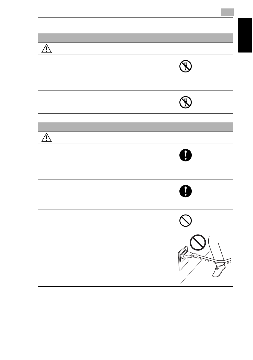
Disassemble and modification
WARNING
• Do not attempt to remove the covers and panels
which have been fixed to the product. Some products
have a high-voltage part or a laser beam source
inside that could cause an electrical shock or
blindness.
• Do not modify this product, as a fire, electrical shock,
or breakdown could result. If the product employs a
laser, the laser beam source could cause blindness.
Power cord
WARNING
• Use only the power cord supplied in the package. If a
power cord is not supplied, only use the power cord
and plug that is specified in POWER CORD
INSTRUCTION. Failure to use this cord could result in
a fire or electrical shock.
• Use the power cord supplied in the package only for
this machine and NEVER use it for any other product.
Failure to observe this precaution could result in a fire
or electrical shock.
• Do not scratch, abrade, place a heavy object on, heat,
twist, bend, pull on, or damage the power cord. Use of
a damaged power cord (exposed core wire, broken
wire, etc.) could result in a fire or breakdown.
Should any of these conditions be found, immediately
turn OFF the power switch, unplug the power cord
from the power outlet, and then call your authorized
service representative.
1
Introduction Chapter 1
1-5
Page 17
1
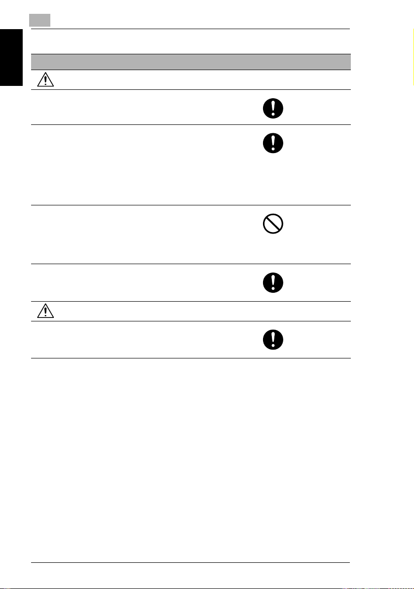
Power source
WARNING
• Use only the specified power source voltage. Failure
to do that could result in a fire or electrical shock.
• Connect power plug directly into wall outlet having the
Introduction Chapter 1
same configuration as the plug. Use of an adapter
leads to the product connecting to inadequate power
supply (voltage, current capacity, grounding), and
may result in fire or shock. If proper wall outlet is not
available, the customer shall ask qualified electrician
for the installation.
• Do not use a multiple outlet adapter nor an extension
cord in principle. Use of an adapter or an extension
cord could cause a fire or electrical shock.
Contact your authorized service representative if an
extension cord is required.
• Consult your authorized service representative before
connecting other equipment on the same wall outlet.
Overload could result in a fire.
1.2 Safety Information
CAUTION
• The outlet must be near the equipment and easily
accessible. Otherwise you can not pull out the power
plug when an emergency occurs.
1-6
Page 18
1.2 Safety Information
Power plug
WARNING
• Do not unplug and plug in the power cord with a wet
hand, as an electrical shock could result.
• Plug the power cord all the way into the power outlet.
Failure to do this could result in a fire or electrical
shock.
CAUTION
• Do not tug the power cord when unplugging. Pulling
on the power cord could damage the cord, resulting in
a fire or electrical shock.
• Remove the power plug from the outlet more than one
time a year and clean the area between the plug
terminals. Dust that accumulates between the plug
terminals may cause a fire.
Grounding
WARNING
• Connect the power cord to an electrical outlet that is
equipped with a grounding terminal.
1
Introduction Chapter 1
1-7
Page 19
1
Installation
WARNING
• Do not place a flower vase or other container that
contains water, or metal clips or other small metallic
objects on this product. Spilled water or metallic
objects dropped inside the product could result in a
Introduction Chapter 1
fire, electrical shock, or breakdown.
Should a piece of metal, water, or any other similar
foreign matter get inside the product, immediately turn
OFF the power switch, unplug the power cord from
the power outlet, and then call your authorized service
representative.
CAUTION
• After installing this product, mount it on a secure
base. If the unit moves or falls, it may cause personal
injury.
• Do not place the product in a dusty place, or a site
exposed to soot or steam, near a kitchen table, bath,
or a humidifier. A fire, electrical shock, or breakdown
could result.
• Do not place this product on an unstable or tilted
bench, or in a location subject to a lot of vibration and
shock. It could drop or fall, causing personal injury or
mechanical breakdown.
• Do not let any object plug the ventilation holes of this
product. Heat could accumulate inside the product,
resulting in a fire or malfunction.
• Do not use flammable sprays, liquids, or gases near
this product, as a fire could result.
1.2 Safety Information
Ventilation
CAUTION
• Always use this product in a well ventilated location.
Operating the product in a poorly ventilated room for
an extended period of time could injure your health.
Ventilate the room at regular intervals.
1-8
Page 20
1.2 Safety Information
Actions in response to troubles
WARNING
• Do not keep using this product, if this product
becomes inordinately hot or emits smoke, or unusual
odor or noise. Immediately turn OFF the power
switch, unplug the power cord from the power outlet,
and then call your authorized service representative.
If you keep on using it as is, a fire or electrical shock
could result.
• Do not keep using this product, if this product has
been dropped or its cover damaged. Immediately turn
OFF the power switch, unplug the power cord from
the power outlet, and then call your authorized service
representative. If you keep on using it as is, a fire or
electrical shock could result.
CAUTION
• The inside of this product has areas subject to high
temperature, which may cause burns.
When checking the inside of the unit for malfunctions
such as a paper misfeed, do not touch the locations
(around the fusing unit, etc.) which are indicated by a
“Caution HOT” caution label.
1
Introduction Chapter 1
Consumables
WARNING
• Do not throw the toner cartridge or toner into an open
flame. The hot toner may scatter and cause burns or
other damage.
CAUTION
• Do not leave a toner unit or drum unit in a place within
easy reach of children. Licking or ingesting any of
these things could injure your health.
• Do not store toner units and PC drum units near a
floppy disk or watch that are susceptible to
magnetism. They could cause these products to
malfunction.
1-9
Page 21

1
When moving the machine
CAUTION
• Whenever moving this product, be sure to disconnect
the power cord and other cables. Failure to do this
could damage the cord or cable, resulting in a fire,
electrical shock, or breakdown.
• When moving this product, always hold it by the
Introduction Chapter 1
locations specified in the User manual or other
documents. If the unit falls it may cause severe
personal injury. The product may also be damaged or
malfunction.
1.2 Safety Information
1-10
Page 22

1.2 Safety Information
47 CFR - Telecommunication Devices
This equipment complies with Part 68 of the FCC rules and the requirements
adopted by the ACTA (Administrative Council for Terminal Attachments).
On the rear side of this equipment is a label that contains, among other information,
a product identifier in the format US:E8OFA03BFAX2900. If requested, this number
must be provided to the telephone company.
This equipment uses THE FOLLOWING USOC JACKS: RJ11C.
The REN is used to determine the number of devices that may be connected to a
telephone line.
Excessive RENs on a telephone line may result in the devices not ringing in
response to an incoming call.
It most but not all areas, the sum of RENs should not exceed five (5.0). To be a
certain of the number of devices that may be connected to a line, as determined by
the total RENs, contact the local telephone company. For products approved after
July 23, 2001, the REN for this product is part of the product identifier that has the
format US:E8OFA03BFAX2900.
The digits represented by 0.3B are the REN without a decimal point (e.g.,03 is a
REN of 0.3).
For earlier products, the REN is separately shown on the label.
If your telephone equipment causes harm to the telephone network, the Telephone
Company may discontinue your service temporarily. If possible, they will notify you
in advance. But if advance notice isn’t practical, you will be notified as soon as
possible. You will be advised of your right to file a complaint with the FCC.
Your telephone company may make changes to its facilities, equipment,
operations, or procedures that could affect the proper operation of your equipment.
If they do, you will be given advance notice so as to give you an opportunity to
maintain uninterrupted service.
If you experience trouble with this equipment, please contact:
Konica Minolta Business Solution U.S.A.,Inc.
100 Williams Drive Ramsey.
New Jersey 07446
U.S.A
The telephone company may ask you to disconnect this equipment from the
network until the problem has been corrected or you are sure that the equipment is
not malfunctioning.
This equipment may not be used on coin service provided by the telephone
company. Connection to party lines is subject to state tariffs. (Contact your state
public utility commission or corporation commission for information.)
Customer Information For Privately Owned Coin Phones
1
Introduction Chapter 1
1-11
Page 23

1
To comply with state tariffs, the telephone company must be given notification prior
to connection.
In some states, prior approval of connection must be obtained from the state Public
Utility Commission, Public Service Commission or state Corporation Commission.
Warning For Setting Of Header And Footer
TheTelephone Consumer Protection Act of 1991 makes it unlawful for any person
to use a computer or other electronic device to send any message via a telephone
fax machine unless such message clearly contains in a margin at the top or bottom
Introduction Chapter 1
each transmitted page or on the first page of the transmission, the date and time it
is sent and an identification of the business or other entity, or other individual
sending the message and the telephone number of the sending machine or such
business, other entity, or individual.
In order to program this information into your fax machine, you should complete the
following steps. (Refer to Chapter 7, page 7-58 and page 7-67.)
IC CS-03-Telecommunication Devices
The following note shall be conspicuously placed in the user manual: The team “IC:”
before the certification/registration number only signifies that the Industry Canada
technical specifications were met.
NOTICE:
This equipment meets the applicable Industry Canada Terminal Equipment
Technical Specifications.
This is confirmed by the registration number. The abbreviation, IC, before the
registration number signifies that registration was performed based on a
Declaration of Conformity indicating that Industry Canada technical specifications
were met. It does not imply that Industry Canada approved the equipment.
Before installing this equipment, users should ensure that it is permissible to be
connected to the facilities of the local telecommunications company. The
equipment must also be installed using an acceptable method of connection. In
some cases, the company’s inside wiring associated with a single line individual
service may be extended by means of certified connector assembly (telephone
extension cord). The customer should be aware that compliance with the above
conditions may not prevent degradation of service in some situations.
Repairs to certified equipment should be made by an authorized Canadian
maintenance facility designed by the supplier. Any repairs or alterations made by
the user to this equipment, or equipment malfunctions, may give the
telecommunications company cause to request the user to disconnect the
equipment.
Users should ensure for their own protection that the electrical ground connections
of the power utility, telephone lines, and internal metallic water pipe system, if
1.2 Safety Information
1-12
Page 24

1.2 Safety Information
present, are connected together. This precaution may be particularly important in
rural areas.
CAUTION:
Users should not attempt to make such connections themselves, but should contact
the appropriate electric inspection authority, or electrician, as appropriate.
NOTICE:
The Ringer Equivalence Number (REN)
The REN assigned to each terminal equipment provides an identification of the
maximum number of terminals allowed to be connected to a telephone interface.
The termination on an interface may consist of any combination of devices subject
only to the requirement that the sum of the Ringer Equivalence Numbers of all the
devices does not exceed five.
REN=0.2
Laser Safety
This is a digital machine which operates using a laser. There is no possibility of
danger from the laser provided the machine is operated according to the
instructions in this manual.
Since radiation emitted by the laser is completely confined within a protective
housing, the laser beam cannot escape from the machine during any phase of user
operation.
This machine is certified as a Class 1 laser product: This means the machine does
not produce hazardous laser radiation.
for this terminal equipment is as follows.
1
Introduction Chapter 1
Internal Laser Radiation
Maximum Average Radiation Power: 36.903 µW at the laser aperture of the print
head unit.
Wavelength: 770-800 nm
This product employs a Class 3b laser diode that emits an invisible laser beam.
The laser diode and the scanning polygon mirror are incorporated in the print head
unit.
The print head unit is NOT A FIELD-SERVICEABLE ITEM.
Therefore, the print head unit should not be opened under any circumstances.
1-13
Page 25
Introduction Chapter 1
1
1.2 Safety Information
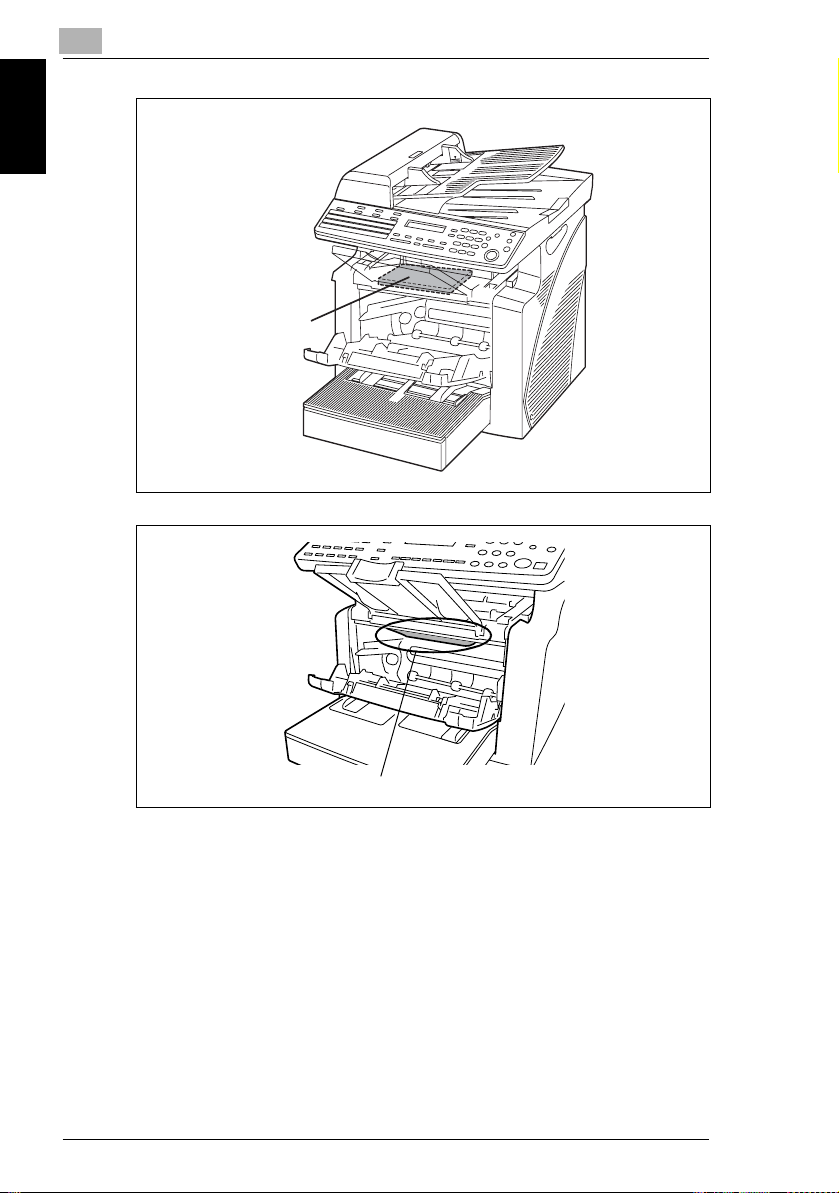
Print Head
Laser Aperture of the Print Head Unit
There is a laser aperture at the location shown above, which must NEVER be
viewed directly by the user.
CDRH Regulation
This machine is certified as a Class 1 Laser product under Radiation Performance
Standard according to the Food, Drug and Cosmetic Act of 1990. Compliance is
mandatory for Laser products marketed in the United States and is reported to the
Center for Devices and Radiological Health (CDRH) of the U.S. Food and Drug
Administration of the U.S. Department of Health and Human Services (DHHS). This
means that the device does not produce hazardous laser radiation.
1-14
Page 26

1.2 Safety Information
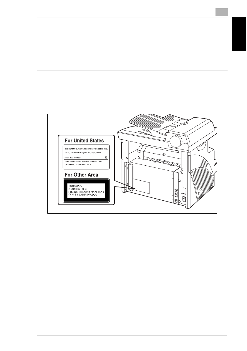
The label shown on page 1-17 indicates compliance with the CDRH regulations and
must be attached to laser products marketed in the United States.
CAUTION
Use of controls, adjustments or performance of procedures other than those
specified in this manual may result in hazardous radiation exposure.
This is a semiconductor laser. The maximum power of the laser diode is 15 mW and
the wavelength is 770-800 nm.
For European Users
CAUTION
Use of controls, adjustments or performance of procedures other than those
specified in this manual may result in hazardous radiation exposure.
This is a semiconductor laser. The maximum power of the laser diode is 15 mW and
the wavelength is 770-800 nm.
For Denmark Users
ADVARSEL
Usynlig laserstråling ved åbning, når sikkerhedsafbrydere er ude af funktion.
Undgå udsættelse for stråling. Klasse 1 laser produkt der opfylder IEC60825
sikkerheds kravene.
Dansk: Dette er en halvlederlaser. Laserdiodens højeste styrke er 15 mW og
bølgelængden er 770-800 nm.
1
Introduction Chapter 1
For Finland, Sweden Users
LOUKAN 1 LASERLAITE
KLASS 1 LASER APPARAT
VAROITUS!
Laitteen Käyttäminen muulla kuin tässä käyttöohjeessa mainitulla tavalla saattaa
altistaa käyttäjän turvallisuusluokan 1 ylittävälle näkymättömälle lasersäteilylle.
Tämä on puolijohdelaser. Laserdiodin sunrin teho on 15 mW ja aallonpituus on 770800 nm.
1-15
Page 27

1
VARNING!
Om apparaten används på annat sätt än i denna bruksanvisning specificerats,
kan användaren utsättas för osynlig laserstrålning, som överskrider gränsen för
laserklass 1.
Det här är en halvledarlaser. Den maximala effekten för laserdioden är 15 mW och
våglängden är 770-800 nm.
Introduction Chapter 1
VARO!
Avattaessa ja suojalukitus ohitettaessa olet alttiina näkymättömälle
lasersäteilylle. Älä katso säteeseen.
VARNING!
Osynlig laserstrålning när denna del är öppnad och spärren är urkopplad.
Betrakta ej strålen.
1.2 Safety Information
1-16
Page 28
1.2 Safety Information
For Norway Users
ADVERSEL
Dersom apparatet brukes på annen måte enn spesifisert i denne bruksanvisning,
kan brukeren utsettes for unsynlig laserstråling som overskrider grensen for laser
klass 1.
Dette en halvleder laser. Maksimal effekt till laserdiode er 15 mW og bølgelengde
er 770-800 nm.
Laser Safety Label
A laser safety label is attached to the outside of the machine as shown below.
1
Introduction Chapter 1
1-17
Page 29

1
Ozone Release
CAUTION
Locate the Machine in a Well-Ventilated Room
§ A negligible amount of ozone is generated during normal operation of this
machine. An unpleasant odor may, however, be created in poorly ventilated
Introduction Chapter 1
rooms during extensive machine operations. For a comfortable, healthy, and
safe operating environment, it is recommended that the room be well ventilated.
REMARQUE
= Placer l’appareil dans une pièce largement ventilée =
Une quantité d’ozone négligable est dégagée pendant le fonctionnement de
l’appareil quand celui-ci est utilisé normalement. Cependant, une odeur
désagréable peut être ressentie dans les pièces dont l’aération est insuffisante et
lorsque une utilisation prolongée de l’appareil est effectuée. Pour avoir la
certitude de travailler dans un environnement réunissant des conditions de
confort, santé et de sécurité, il est préférable de bien aérer la pièce où se trouve
l’appareil.
Acoustic Noise
For European Users
Machine Noise Regulation 3 GSGV, 18.01.1991 : The sound pressure level at the
operator position according to EN 27779 is equal to or less than 70dB(A).
1.2 Safety Information
Notice for Ni-MH Batteries
Ni-MH (Nickel Metal Hydride) Batteries are installed inside machine as back up
memory batteries. Please dispose according to local, state and federal regulations.
1-18
Page 30

1.3 Energy Star®
1
1.3 Energy Star
As an ENERGY STAR® Partner, we have determined that this machine meets the
ENERGY STAR
What is an ENERGY STAR
An ENERGY STAR
switch to a “low-power mode” after a period of inactivity. An ENERGY STAR
product uses energy more efficiently, saves you money on utility bills and helps
protect the environment.
®
Guidelines for energy efficiency.
®
®
Product?
®
product has a special feature that allows it to automatically
®
Introduction Chapter 1
1-19
Page 31

1
1.4 Explanation of Manual Conventions
1.4 Explanation of Manual Conventions
The marks and text formats used in this manual are described below.
WARNING
Failure to observe instructions highlighted in this manner may result in fatal
or critical injuries.
§ Observe all warnings in order to ensure safe use of the machine.
Introduction Chapter 1
CAUTION
Failure to observe instructions highlighted in this manner may result in
serious injuries or property damage.
§ Observe all cautions in order to ensure safe use of the machine.
Note*
(*May also appear as “Important” or “Tip”)
Text highlighted in this manner contains useful information and tips to ensure
safe use of the machine.
1 The number 1 as formatted here indicates the
first step of a sequence of actions.
2 Subsequent numbers as formatted here
indicate subsequent steps of a sequence of
actions.
Text formatted in this style provides
?
additional assistance.
§ Text formatted in this style describes the
action that will ensure the desired results are achieved.
[Copy] key
The names of keys on the control panel are written as shown above.
1-20
An illustration inserted here shows
what operations must be performed.
Page 32

1.5 Explanation of Basic Concepts and Symbols
1
1.5 Explanation of Basic Concepts and Symbols
The use of words and symbols in this manual are explained below.
Paper Feeding
During printing, paper is supplied from the front side of the machine and fed into the
Copy Tray on top with the printed surface of the page facing down. The paper feed
direction is shown by the arrows in the diagram below.
Introduction Chapter 1
1-21
Page 33

1
“Width” and “Length”
Whenever paper dimensions are mentioned in
this manual, the first value always refers to the
width of the paper (shown as “A” in the
illustration) and the second to the length (shown
as “B”).
A: Width
B: Length
Introduction Chapter 1
Paper Orientation
Lengthwise ( )
If the width (A) of the paper is shorter than the
length (B), the paper has a vertical or portrait
orientation, indicated by either “L” or .
1.5 Explanation of Basic Concepts and Symbols
Crosswise ( )
If the width (A) of the paper is longer than the
length (B), the paper has a horizontal or
landscape orientation, indicated by either “C” or
.
1-22
Page 34

2
Precautions
Precautions Chapter 2
2
Page 35

2
Observe the following precautions to maintain the machine in its best possible
condition.
2.1 Installation Precautions
2.1 Installation Precautions
Installation Site
To ensure utmost safety and prevent possible malfunctions, install the machine in
a location that meets the following requirements:
- A location away from curtains, etc. that may catch fire and burn easily
- A location that is not exposed to water or other liquids
- A location free from direct sunlight
- A location out of the direct airflow of an air conditioner or heater, and not
Precautions Chapter 2
exposed to extremely high or low temperatures
- A well-ventilated location
- A location that is not exposed to high humidity
- A location that is not extremely dusty
- A location not subjected to undue vibrations
- A stable and level location
- A location where ammonia or other organic gases are not generated
- A location that does not put the operator in the direct airflow of exhaust from the
machine
- A location that is not near any kind of heating devices
Power Source
The power source requirements are as follows.
G Voltage Fluctuation: AC110V -10%, AC127V +6%, or AC220-240 V ±10%
G Frequency Fluctuation: Within ±3Hz
H Use a power source with as few voltage or frequency fluctuations as possible.
2-2
Page 36

2.1 Installation Precautions
Space Requirements
To ensure easy machine operation, supply replacement, and maintenance, adhere
to the recommended space requirements detailed below.
2
516mm
( 20.3inch )
719nn
( 24inch )
772mm
( 30.4inch )
Note
In order to enable easy machine maintenance and replacement of
consumables, maintain an adequate amount of space around the machine.
When lifting the machine, be sure to grab the handles on the left and right sides
from the rear of the machine. If the machine is lifted from its front, it may become
unbalanced and fall.
Precautions Chapter 2
2-3
Page 37

2
2.2 Operation Precautions
2.2 Operation Precautions
Operating Environment
The environmental requirements for correct operation of the machine are as
follows:
G Temperature: 50°F to 86°F with fluctuations of no more than 18°F within an hour
G Humidity: 15% to 85% with fluctuations of no more than 10% within an hour
Proper Use
To ensure the optimum performance of the machine, follow the precautions listed
below:
- Never place heavy objects on the Original Glass or subject it to shocks.
Precautions Chapter 2
- Never open any machine doors or turn off the machine while it is making copies/
printing, as a paper misfeed could result.
- Never bring any magnetized object, or use flammable sprays or liquids, near the
machine.
Always make sure that the power plug is completely plugged into the electrical
output.
- Always make sure that the machine’s power plug is visible and not hidden by
the machine.
Always unplug the machine from the electrical outlet if the machine is not to be
used for a long period of time.
Always provide good ventilation when making a large number of continuous
copies/printed pages.
CAUTION
A negligible amount of ozone is generated during normal operation of this
machine. An unpleasant odor may, however, be detected in poorly ventilated
rooms during extensive machine operations.
§ For a comfortable operating environment, it is recommended that the room be
well ventilated.
2-4
Page 38

2.2 Operation Precautions
CAUTION
The area around the Fusing Unit is extremely hot.
§ In order to reduce the risk of burns, do not touch any area other than those
indicated in the manual. Be especially careful not to touch parts marked with
warning labels, and their surrounding areas.
Transporting the Machine
If you need to transport the machine over a long distance, consult your service
representative.
2
Care of Machine Supplies
Use the following precautions when handling the machine supplies (toner, paper,
etc.).
Store the supplies in a location that meets the following requirements:
Free from direct sunlight
Away from any heating apparatus
Not subjected to high humidity
Not extremely dusty
Paper that has been removed from its wrapper but not loaded in the machine
should be stored in a sealed plastic bag in a cool, dark place.
- Use only toner that has been manufactured specifically for this machine. Never
use other types of toner.
- Keep all supplies out of the reach of children.
CAUTION
Be careful not to spill toner inside the machine or get toner on your clothes
or hands.
§ If your hands become soiled with toner, immediately wash them with soap and
water.
Precautions Chapter 2
2-5
Page 39

2
2.3 Legal Restrictions on Copying
2.3 Legal Restrictions on Copying
Certain types of documents must not be copied with the purpose or intent to pass
copies of such documents off as the originals.
The following is not a complete list, but is meant to be used as a guide to
responsible copying.
<Financial Instruments>
G Personal checks
G Travelers checks
G Money orders
G Certificates of deposit
G Bonds or other certificates of indebtedness
G Stock certificates
Precautions Chapter 2
<Legal Documents>
G Food stamps
G Postage stamps (canceled or uncanceled)
G Checks or drafts drawn by government agencies
G Internal revenue stamps (canceled or uncanceled)
G Passports
G Immigration papers
G Motor vehicle licenses and titles
G House and property titles and deeds
<General>
G Identification cards, badges, or insignias
G Copyrighted works without permission of the copyright owner
In addition, it is prohibited under any circumstances
currencies, or works of art, without permission of the copyright owner.
When in doubt about the nature of a document, consult with legal counsel.
to copy domestic or foreign
2-6
Page 40

3
Before Making
Copies or
Faxing
3
Before Making Copies or Faxing Chapter 3
Page 41

3
3.1 Available Features
3.1 Available Features
The main copy settings available with this machine are listed below. For details on
their operation, refer to the pages indicated.
Copies
G 1-sided copies (p. 4-2)
G 2in1 copies (p. 4-13)
Note
Available only with
FAX3900
Zoom Ratio
G Reduced/Full Size/Enlarged
(p. 4-9)
Before Making Copies or Faxing Chapter 3
Finishing
G Sort (p. 4-14)
3-2
Page 42

3.2 Components and Their Functions
3
3.2 Components and Their Functions
Main Unit
G FAX2900/3900
Paper Feed Cassette (option)
G Capable of holding up to 500 sheets of paper.
32 MB Memory (option only for FAX3900)
G Increases the machine’s memory. By increasing the machine’s memory, more
pages can be scanned.
3-3
Before Making Copies or Faxing Chapter 3
Page 43
3
3.3 Parts Names and Their Functions
3.3 Parts Names and Their Functions
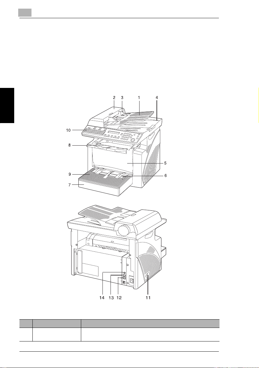
Main Unit
Before Making Copies or Faxing Chapter 3
No.
Part Name
1 Document Feeder Tray Load the originals to be scanned face up on this tray.
3-4
Description
Up to 50 document sheets can be loaded at one time.
Page 44

3.3 Parts Names and Their Functions
No. Part Name Description
2 Document Feeder
Cover (Doc. Feed
Cover)
3 Document Guide Plate Slide the guide plate to the size of the originals.
4 Document Exit Tray Receives originals which have been scanned by the machine.
5 Front Cover Opened when replacing the Toner Cartridge or drum cartridge, or
6 Bypass Tray Used to manually feed paper.
7 Tray1 door If Legal-size paper is installed, open this door.
8 Copy Tray Holds copies fed out face down from the machine.
9 Tray1 Holds up to 250 sheets of paper and easily adjusts to different paper
10 Control Panel Used to start a print cycle and make necessary settings.
11 Power Switch Used to turn the machine on and off.
12 External telephone jack
(TEL PORT)
13 Telephone line jack for
line 1 (LINE PORT 1)
14 USB Port For details, refer to the User Manual for the printer controller.
Opened when clearing an original that has been misfed.
clearing a paper misfeed.
Holds up to 10 sheets of plain paper.
The Copy Tray can be adjusted to one of three angles. Adjust the Copy
Tray to the angle appropriate for its application.
sizes.
Special paper can be used.
Used for connecting a line to a telephone.
Used for connecting to a standard telephone line.
3
Inside the Machine
No. Part Name Description
1 Imaging Cartridge Generates the print image.
The Imaging Cartridge is constructed of both the Drum Cartridge and
the Toner Cartridge set into place.
Before Making Copies or Faxing Chapter 3
1
3-5
Page 45

3
Adjusting the Angle of the Copy Tray
e Copy Tray can be adjusted to one of three angles. Adjust the tray to the angle
Th
appropriate for the desired application.
1. Normal operation (standard position)
2. When back curled paper is fed out
3. When clearing a paper misfeed or replacing the Drum Cartridge or Toner
Cartridge
3.3 Parts Names and Their Functions
Before Making Copies or Faxing Chapter 3
Note
Adjust the Tray Extension and Paper Stopper to fit the size of the paper.
For Legal-size paper
For A4-size paper
For Letter-size paper
3-6
Page 46

3.3 Parts Names and Their Functions
Paper Feed Cassette (option)
3
No. Part Name
1 Tray2 Holds up to 500 sheets of paper.
Description
Before Making Copies or Faxing Chapter 3
3-7
Page 47

3
3.4 Control Panel
Names of Control Panel Parts and Their Functions
For FAX3900
3.4 Control Panel
Before Making Copies or Faxing Chapter 3
1
Printer Status
2
3
29
30
Auto/Photo
4
Auto RX
Memory TX
01/33
09/41
17/49
25/57
Utility
22
Paper
56
02/34
10/42
18/50
26/58
21
20
Error
@
Yes
No
2in1
Sort
Zoom
8
7
9
28
27
Resolution
ABC
GHI
JKL
C
PORS
TUV
11
10
25
Phone Book
Speaker
04/36
12/44
20/52
28/60
05/37
13/45
21/53
29/61
03/35
11/43
19/51
27/59
1819
DEF
123/ABC
MNO
Stop
WXYZ
12
Redial/Pause
06/38
14/46
22/54
30/62
07/39
15/47
23/55
31/63
17
Scan
Start
2326
Fax
Copy
Panel Reset
13
Speed Dial
Function
08/40
16/48
24/56
32/64
16
15
14
24
3-8
Page 48

3.4 Control Panel
For FAX2900
3
1
Printer Status
2
3
29
30
Utility
Auto/Photo
4
Auto RX
Memory TX
Paper
56 8
01
09
17
DEF
MNO
WXYZ
06
14
22
1819
123/ABC
Stop
12
07
15
23
Fax
Panel Reset
Start
13
2326
Speed Dial
08
16
24
Copy
24
Function
16
15
14
Before Making Copies or Faxing Chapter 3
2122
20
Error
@
Yes
No
Sort
Zoom
9
28
27
Resolution
Speaker
02
03
04
12
11
10
20
19
18
ABC
GHI
JKL
C
PORS
TUV
11
10
25
Phone Book
Redial/Pause
05
13
21
25
27
26
28
30
29
31
32
3-9
Page 49

3
No. Part Name Description
1 [Utility] key Press to enter Utility mode.
2 [Printer] key Press to enter Printer mode.
Ö
3[] [Ö ] key • Press to adjust the image density.
4 [Auto/Photo] key Press to change the image density mode.
5 [Status] key Press to view the counters and transmission results. In addition, the list
6 [Paper] key Press to select the paper tray and paper source.
7 [2in1] key Press to select the 2in1 function.
8[▲] [▼] key • Press to change the zoom ratio in the range between
For details, refer to “Utility Mode” on page 7-2.
For details, refer to the User Manual for the printer controller.
• Press to specify the various settings.
of settings specified for each function and the reports can be printed.
(p. 3-31)
Available only with FAX3900
3.4 Control Panel
× 2.00 in × 0.01 increments.
• Press to scan through the various settings and information, in order.
• Press to specify the various settings.
9 [Zoom] key Press to select a zoom ratio from among the standard fixed ones
10 [Sort] key Press to select the sort function.
11 10-key pad • Used to enter the number of copies to be made and any other
12 [Stop] key • Press to stop a print cycle.
Before Making Copies or Faxing Chapter 3
13 [Start] key • Press to start a scanning or print cycle.
14 [Panel Reset] key Press to reset all print functions and settings to their defaults.
15 [Copy] key Press to enter Copy mode. The indicator lights up in green to indicate
16 [Fax] key Press to enter Fax mode. The indicator lights up in green to indicate that
17 [Scan] key Press to enter Scan mode. The indicator lights up in green to indicate
18 [123/ABC] key Press to switch the 10-Key Pad between typing in numbers and typing
19 Error lamp The indicator lights up in orange if an error or malfunction occurs.
available.
numeric data.
• Used to enter text such as a name.
• In the Fax mode, use the [ ] key for tone transmission (with pulse
dialing) and use the [#] key for accessing an outside line.
• Press to stop a scanning sequence.
• Stops the fax transmission or reception.
• The indicator flashes in orange when the machine is paused or while
printing.
• Starts a fax transmission.
• Press to specify the various settings.
• The indicator lights up in green when the machine can accept print jobs.
that the machine is in Copy mode.
the machine is in Fax mode.
that the machine is in Scan mode.
Available only with FAX3900
in letters.
Ö
× 0.50 and
3-10
Page 50

3.4 Control Panel
No. Part Name Description
20 [Yes] key • Press to validate the setting just made.
21 [No]/[C] key • Press to reset the number of copies to “1”.
22 Display Shows the number of copies to be made, the zoom ratio, and other
23 [Function] key Used to select a function.
24 [Speed Dial] key Used to dial pr eviously programmed fax numbers represen ted by 3-digit
25 [Redial/Pause] key • Redials the last number called.
26 [Phone Book] key Used to display the information programmed for one-touch dialing,
27 [Speaker] key Press to answer the call. Press again to hang up.
28 [Resolution] key Used to select the image quality (transmission resolution).
29 Memory TX/Auto RX
lamp
30 One-touch dial key Used to dial previously programmed fax numbers.
• Press to specify the various settings.
• Press to clear the various settings.
• Press to return to the previous screen.
• Press to specify the various settings.
• Erases the entered numbers and letters.
setting data.
• BROADCAST (broadcast transmission), TIMER TX (timer
transmission), MAILBOX TX (mailbox transmission), PRINT MAILBOX
RX (retrieve mailbox faxes), POLLING TX (polling transmission),
POLLING RX (polling reception), RELAY INITIATE (relay initiation
transmission), CANCEL RESERV. (cancel queued job), TX MODE
(transmission mode), INTERNET FAX RX
Available only with FAX3900
numbers.
• While dialing, used to generate a pause when transferring from an
internal to an external line or receiving information services.
group dialing and speed dialing.
Used to select the Memory TX or Auto RX function
3
Before Making Copies or Faxing Chapter 3
3-11
Page 51

3
3.4 Control Panel
Display Indications
In Copy mode:
12 3
[A]
45
No. Display Indication Description
1 Document type Displays the document type currently specified for the image density.
2 Zoom ratio Displays the currently specified zoom ratio.
3 Number of copies Displays the currently specified number of copy pages and number of
4 Image density Displays the currently specified image density.
5 Paper Displays the currently selected paper tray, paper size, and paper type.
copy sets.
In Fax mode:
Before Making Copies or Faxing Chapter 3
345 6
2
1
1
2
No. Display Indication Description
1 Messages Displays messages such as operating instructions.
2 Mode or function name • Displays the current menu, function or settings.
3-12
SCAN TO E-MAIL/FILE
• Error messages are displayed when errors occur.
Page 52

3.4 Control Panel
No. Display Indication Description
3 Time The current time is displayed during standby.
4 Resolution The setting resolution is displayed during standby.
5 Symbol Indicates the currently selected mode or function settings.
6 Memory The remaining memory is displayed during standby.
Symbol list:
Symbol Description
Manual bypass Paper is loaded in the Manual Bypass Tray.
3
Custom paper size The paper setting for the Manual Bypass Tray is a custom paper
Dialing A fax number is being dialed.
Ringing The machine is being called.
Sending The document is being sent.
Receiving A document is being received.
In standby for timer
transmission
In standby for polling
transmission
In standby for mailbox
reception
In standby for memory
reception or polling
reception
size.
A document is queued for timer transmission.
A document is queued for polling transmission.
A document is queued for mailbox reception.
A document is queued for memory reception or polling reception.
Before Making Copies or Faxing Chapter 3
3-13
Page 53

3
3.5 Turning the Machine On/Off Initial Mode
3.5 Turning the Machine On/Off Initial Mode
Turning the Machine On/Off
To turn on the machine:
§ Press the | (on) side of the Power
Switch.
To turn off the machine:
§ Press the 2 (off) side of the Power
Switch.
Note
Do not turn off the machine while a print cycle is being performed, as a paper
misfeed will result. Before attempting to turn off the machine, always be sure
that the current print cycle has been completed.
Turning off the machine will initialize all settings except those for previously
programmed jobs and for the Utility mode.
Do not turn off the machine while it is scanning or sending or receiving data,
otherwise all scanned data or transmission data will be deleted.
Before Making Copies or Faxing Chapter 3
The machine automatically enters the Energy Save mode 15 min after the last
operation is performed.
The time until the machine enters Energy Save mode can be specified from the
Utility mode. For details, refer to “Specifying the Setting for “ENERGY SAVE
MODE”” on page 7-6 in the chapter “Using the Utility Mode”.
When the Machine is Turned On
When the machine is turned on, the [Start] key indicator lights up in orange to
indicate that the machine is ready to begin printing.
At this time, the machine can be set for the Auto Print Start function by loading a
document into the Auto Document Feeder, and pressing the [Start] key.
Pressing the [Start] key at this time will not immediately start the print cycle. You will
have to wait for less than 25 seconds (at an ambient temperature of 73.4°F).
3-14
Page 54

3.5 Turning the Machine On/Off Initial Mode
Default Settings
When the machine is turned on, the Initial mode screen appears in the Display of
the Control Panel. The Initial mode screen appears at the beginning of all
operations.
[A]
Factory default settings
G Number of copies: 1
G Image density: TEXT Auto
G Zoom ratio: 100% (full size)
G Paper: Tray1
G Finishing: Non-Sort
3
Tip
The default settings can be customized from the Utility mode. For details, refer
to “Utility Mode” on page 7-2.
Before Making Copies or Faxing Chapter 3
3-15
Page 55

3
3.6 Useful Functions
3.6 Useful Functions
Panel Resetting
Press the [Panel Reset] key to return all modes and functions (zoom ratio, number
of copies, etc.) to their defaults. (All selected settings are canceled.)
Tip
The [Panel Reset] key comes in handy for canceling all selected settings at one
time.
To avoid accidentally using settings from the previous print job, press the [Panel
Reset] key to return all functions and settings to their defaults before specifying
any settings for your current job.
Auto Panel Reset
Even if the [Panel Reset] key is not pressed, the machine automatically resets all
functions and settings to their defaults 1 min after a print cycle has been completed
or a key operation is performed.
Tip
The length of time before the machine automatically resets itself can be set
between 1 min and 5 min in addition to 30 seconds. The Auto Panel Reset
Before Making Copies or Faxing Chapter 3
function can even be disabled.
For details, refer to “Specifying the Setting for “AUTO PANEL RESET”” on
page 7-5.
Energy Save Mode
Instead of turning off the machine, it can be set into a standby state (Energy Save
mode).
If the machine is not used for a set length of time, it will automatically enter the
Energy Save mode. The default length of time is 15 min.
To cancel the Energy Save mode, press any key on the control panel.
Tip
The length of time before the machine enters the Energy Save mode can be set
between 1 min and 240 min.
For details, refer to “Specifying the Setting for “ENERGY SAVE MODE”” on
page 7-6.
3-16
Page 56

3.6 Useful Functions
Auto Print Start
If a document is loaded and the [Start] key is pressed during the period after the
machine has been turned on but before it is ready to make print, the machine will
automatically start the print cycle as soon as it completes the warm-up cycle.
Auto Tray Switching
If the tray runs out of paper while printing, the machine will automatically switch to
a different paper source and continue printing provided that the new tray contains
paper of the same type and size in the same orientation.
If the optional Paper Feed Cassette is installed, a maximum of 750 pages can be
continuously printed.
Tray1 → Tray2 (Paper Feed Cassette)
Tray2 (Paper Feed Cassette) → Tray1
3
Tip
Auto tray switching can be disabled. For details, refer to “Setting Up the Paper
Sources” on page 7-12.
3-17
Before Making Copies or Faxing Chapter 3
Page 57

3
3.7 Entering Text
3.7 Entering Text
When specifying the user name or programming one-touch dial keys with the
recipient name, letters, accented characters, numbers, and symbols can be
entered.
Key operation:
G 10-Key Pad: Used to enter numbers and letters, symbols.
List of characters available with each key of the 10-Key Pad:
10-Key Pad Available characters*
1 . (period) @_ (underscore) - (hyphen) 1
2 ABC2abc
3 DEF3def
4 GHI4ghi
5JKL5jkl
6MNO6mno
7PQRS7pqrs
8TUV8tuv
9 WXYZ9wxyz
+&/ =!?( )%[ ]^‘’{ }|˜$,:;<>“¿£
0 (space) 0
##
* To switch the input mode of the 10-Key Pad between numbers and letters, press the [123/ABC] key.
Before Making Copies or Faxing Chapter 3
Changing Input Mode
Each press of the [123/ABC] key switches the input mode between numbers and
letters.
[1]: Numbers can be typed in.
[A]: Letters can be typed in.
3-18
Page 58

3.7 Entering Text
Inputting Example
To enter the name “NJ Office”
* The cursor (_) flashes alternately with the character at its current location.
Press the [123/ABC] key.
Press the [6] key twice.
Press the [5] key once.
Press the [0] key once.
Press the [6] key 3 times.
3
Press the [3] key 7 times.
Press the [
Press the [3] key 7 times.
Press the [4] key 7 times.
Press the [2] key 7 times.
Press the [3] key 6 times.
Ö ] key.
Before Making Copies or Faxing Chapter 3
3-19
Page 59

3
3.7 Entering Text
Correcting text and input precautions
G To erase all entered text, press the [Panel Reset] key.
G To delete only part of the entered text, use the [ ] and [ ] keys to move the
ÖÖ
cursor (_) to the character that you wish to delete, and then press the [No] key.
G To change an entered character, use the [ ] and [ ] keys to move the cursor
ÖÖ
(_) below the character that you wish to change, and then press the [No] key.
Next, enter the new character. (The character at the cursor's position is
replaced with the new character.)
G If the same 10-Key Pad is needed to enter two characters in a row, press the
Ö
[ ] key after selecting the first character. (Refer to the above example.)
G To enter a space, press 10-Key Pad [0].
Before Making Copies or Faxing Chapter 3
3-20
Page 60

3.8 Copy Paper
3.8 Copy Paper
Paper Specifications
The following table specifies the type and size of paper to be used with each tray
together with its capacity.
Tray1 Specifications
Paper Type • Plain paper, recycled paper (16 lb to 24 lb)
Paper Size • A4 L, B5 L, A5 L, 16K L, Legal L, Letter L, Invoice L, FLS (13
Capacity • Plain paper, recycled paper: 250 sheets (20 lb)
Tray2 Specifications
Paper Type Plain paper, recycled paper (16 lb to 24 lb)
Paper Size Letter L, A4 L*
Capacity 500 sheets (20 lb)
Bypass Tray Specifications
Paper Type • Plain paper, recycled paper (16 lb to 24 lb)
Paper Size • A4 L, B5 L, A5 L, 16K L, Legal L, Letter L, Invoice L, FLS (13
Capacity • Plain paper, recycled paper: 10 sheets (20 lb)
• Exclusive paper: card (24-1/4 lb to 43-1/4 lb) , OHP transparencies,
envelopes
× 8-1/4)
• Custom Size: Width: 3-1/2 to 8-1/2; length: 5-1/2 to 14
• Exclusive paper: card; 5 sheets, OHP transparencies; 5 sheets,
envelopes; 1 sheet
• Exclusive paper: card (24-1/4 lb to 43-1/4 lb) , OHP transparencies,
envelopes, label sheets
× 8-1/4)
• Custom Size: Width: 3-1/2 to 8-1/2; length: 5-1/2 to 14
• Exclusive paper: cards; 1 sheet, OHP transparencies; 1 sheet,
envelopes; 1 sheet
3
Before Making Copies or Faxing Chapter 3
Precautions for Loading Paper
G Be sure to observe the paper specifications (paper type, paper size, and
capacity) for each tray, otherwise a paper misfeed could result.
G When paper is loaded into the Bypass Tray, a message appears, indicating that
the paper size be specified. Specify the size and type of paper that is loaded.
Paper loaded into the Bypass Tray is given priority during feeding.
G The size of FLS is preset to 13 × 8-1/4. To change the FLS size, contact a
service representative.
3-21
Page 61

3
3.8 Copy Paper
Unsuitable Paper
The following types of paper should not be used, otherwise decreased print quality,
paper misfeeds, or damage to the machine may occur.
G Overhead projector transparencies that have already been fed through the
machine
Even if the transparency is still blank, do not reuse it.
G Paper that has been printed on by a heat-transfer printer or an inkjet printer
G Paper that is either extremely thick or extremely thin
G Folded, curled, wrinkled, or torn paper
G Paper that has been left unwrapped for a long period of time
G Damp paper
G Perforated paper or paper with punched holes
G Extremely smooth or extremely rough paper, or paper with an uneven surface
G Paper that has been treated, such as carbon-backed, heat-sensitive or
pressure-sensitive paper
G Paper that has been decorated with foil or embossing
G Paper of a non-standard shape (not rectangular)
G Paper that is bound with glue, staples or paper clips
G Paper with labels attached
G Paper with ribbons, hooks, buttons, etc. attached
G Curled or wrinkled paper
G Art paper, coated paper, or inkjet printer paper
Before Making Copies or Faxing Chapter 3
3-22
Page 62

3.8 Copy Paper
Loading Paper
While loading paper, be sure to observe the following precautions.
G If the paper is curled, flatten it
before loading it.
G Do not load so much paper that
the top of the stack is higher than
the ▼ mark or exceeds the
specified number of sheets.
3
G Push the paper guides firmly up
against the edges of the paper.
G When loading additional paper,
remove any paper remaining in
the drawer, place it on top of the
new paper, and then align the
paper in the stack well, before
loading it into the drawer.
Before Making Copies or Faxing Chapter 3
3-23
Page 63

3
3.8 Copy Paper
G When loading envelopes, load
them with the flap facing down, as
shown in the illustration at the
right.
Note
Before loading envelopes, press
them down to make sure that all air
is removed, and make sure that
the folds of the flaps are firmly
pressed, otherwise the envelopes
may become wrinkled or a paper
misfeed may occur.
Only 1 envelope at a time can be
loaded in Tray1 and the Bypass
Tray.
<Bypass Tray>
<Tray1>
Before Making Copies or Faxing Chapter 3
Tip
We recommend replenishing the paper only after all of the paper in the drawer
has been used.
3-24
Page 64

3.8 Copy Paper
Loading Paper into Tray1
1 Remove the Bypass Tray.
2 Load the paper into the tray so that
the front side of the paper (the side
facing up when the package was
unwrapped) faces up.
3
3 Slide the paper guides against the
edges of the paper.
<When Legal-size paper is installed>
H If Legal-size paper is installed,
open the door of Tray1.
4 Attach the Bypass Tray in its original position.
Before Making Copies or Faxing Chapter 3
3-25
Page 65

3
3.8 Copy Paper
Note
If paper with a different size or type is loaded, various settings must be specified
from the “PAPER SOURCE SETUP” menu in the Utility mode. If the settings are
not correctly specified, paper size error may occur. For details, refer to
“Specifying the Setting for “TRAY SETTING”” on page 7-14.
Before Making Copies or Faxing Chapter 3
3-26
Page 66
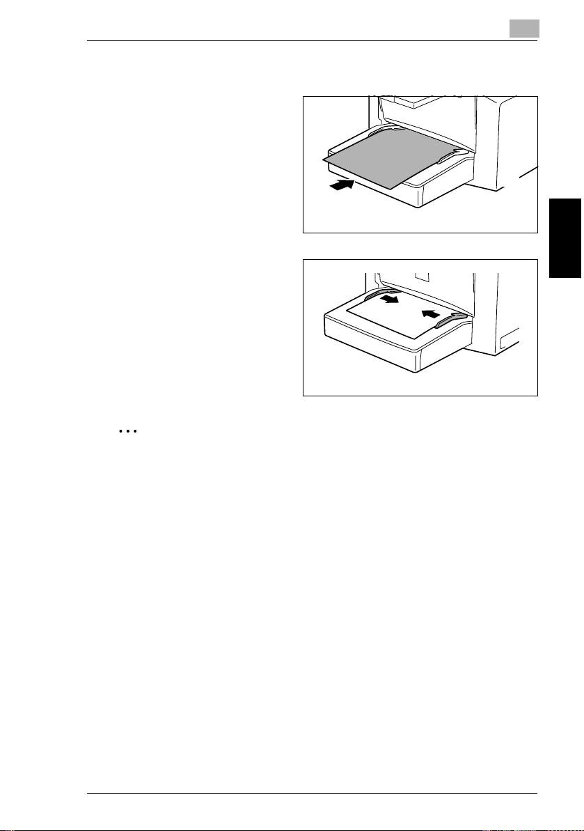
3.8 Copy Paper
Loading Paper into the Bypass Tray
1 Load the paper so that the front
side of the paper (the side facing
up when the package was
unwrapped) faces up.
2 Slide the paper guides against the
edges of the paper.
3
Note
When paper is loaded into the Bypass Tray, the paper size and type must be
specified, otherwise paper size error may occur. For details, refer to “Specifying
the Size and Type on the Manual Bypass Tray” on page 4-5.
3-27
Before Making Copies or Faxing Chapter 3
Page 67

3
Loading Paper into Tray2 (option)
1 Pull out the drawer for Tray2.
2 Remove the drawer cover, and
then press down on the paperlifting plate until it locks into place.
3.8 Copy Paper
Before Making Copies or Faxing Chapter 3
3 Load the paper into the drawer so
that the front side of the paper (the
side facing up when the package
was unwrapped) faces up.
4 Attach the drawer cover, and then return the drawer for Tray2 to its original
position.
3-28
Page 68

3.9 Loading Originals
3
3.9 Loading Originals
Loading Originals in the Auto Document Feeder
The Auto Document Feeder automatically feeds originals one page after another so
that the machine can scan the data on each page. After the machine finishes
scanning the data, the Auto Document Feeder ejects the page into the Exit Tray.
To ensure the best possible performance of the Auto Document Feeder, use only
originals of the specified type.
Specific Types of Originals
Original Loading Original Type Original Size
Auto Document
Feeder
Precautions for Loading Paper Into the Auto Document Feeder
The following types of originals are not suitable for use in the Auto Document
Feeder, as a misfeed or damaged original could result.
G Typing paper, paraffin paper, and other thin paper
G Cards
G Originals larger than Legal L or smaller than Invoice
G OHP transparencies, translucent paper
G Wrinkled, dog-eared, curled, or torn originals
G Clipped or stapled originals
G Coated originals such as carbon-backed paper
G Up to 20 Letter-size document pages can be scanned and stored in the memory
at one time. However, if the optional expansion memory is installed, up to 170
scanned pages can be stored
Sheet originals
Weight of originals: 9-1/4 lb to 34 lb
A4 L, B5 L, A5 L, Legal L to Invoice,
16K L, FLS
• Original width: 5-1/2 to 8-1/2
• Original length: 5 to 14
Before Making Copies or Faxing Chapter 3
3-29
Page 69

3
Loading Originals into the Auto Document Feeder
3.9 Loading Originals
1 Place the stack of originals face up
on the auto Document Feeder
Tray.
Note
A maximum of 50 document
pages can be loaded.
Do not load so many pages that the top of the stack is higher than the t mark.
Be sure to adjust the document guides so that they are against the edges of
the document, otherwise the document may not be fed in straight.
2 Slide the front adjustable
Document Guide Plate to the size
of the originals.
3 Specify the desired copy or fax settings.
Before Making Copies or Faxing Chapter 3
H “Making Copies” on page 4-1
H “Basic Faxing” on page 5-13
4 Press the [Start] key to start
feeding and copying the originals
from the top page.
3-30
Page 70

3.10 Checking the Machine Status
3.10 Checking the Machine Status
The total number of pages printed and scanned since this machine was installed
can be checked.
Menu Item Description
TOTAL PAGE TOTAL COUNT Displays the total number of pages printed since
TOTAL SCAN Displays the total number of pages scanned
TX PAGES Displays the total number of pages faxed since
RX PAGES Displays the total number of pages received
TX/RX RESULT TX RESULT REPORT Displays the transmission result report.
RX RESULT REPORT Displays the reception result report.
PRINT REPORT TX RESULT REPORT Prints the transmission result report.
RX RESULT REPORT Prints the reception result report.
ACTIVITY REPORT Prints the transmission/reception result report.
MEMORY DATA LIST Prints the list of documents stored in the
MEMORY IMAGE PRINT Prints the reduced image of the first page of the
ONE-TOUCH LIST Prints the recipients programmed in the one-
SPEED DIAL LIST Prints the recipients programmed for the speed
KEY SETTING LIST Prints the settings specified for one-touch dial
MACHINE STATUS Prints the current machine status.
CONFIGRATION PAGE Prints the current machine configuration.
RELAY BOX LIST
Available only with FAX3900
this machine was installed.
since this machine was installed.
However, the scanned number of pages in copy
are not included.
this machine was installed.
since this machine was installed.
memory.
document stored in the memory.
touch dial keys.
dial numbers.
keys.
Prints the Relay Box list
3
Before Making Copies or Faxing Chapter 3
3-31
Page 71

3
Checking the “TOTAL PAGE” Counts
1 Press the [Status] key.
2 Press the [Yes] key.
3 Press the [▼] and [▲] keys to
check the “TOTAL COUNT”,
“TOTAL SCAN”, “TX PAGES”, or
“RX PAGES” values.
3.10 Checking the Machine Status
Yes
Before Making Copies or Faxing Chapter 3
3-32
Page 72

3.10 Checking the Machine Status
Checking the “TX/RX RESULT”
1 Press the [Status] key twice.
2 Press the [Yes] key.
Yes
3 Press the [▲] and [▼] keys to
display the desired transmission
results to check them.
H In the transmission result
screen, “TX” indicates sent
faxes, and “RX” indicates
received ones.
H If the [No] key is pressed twice
while the transmission results
are displayed, the main screen
appears.
H To print the transmission result report, press the [Start] key. After the
transmission result report is printed, the main screen appears.
3
Before Making Copies or Faxing Chapter 3
3-33
Page 73

3
To output a report/list
1 Press the [Status] key 3 times.
2 Press the [Yes] key.
3 Press the [▲] and [▼] keys to
select the report/list that you wish
to print, and then press the [Yes]
key.
After the specified report/list is
Before Making Copies or Faxing Chapter 3
printed, the main screen appears again.
3.10 Checking the Machine Status
Yes
Tip
The reception/transmission result reports can be checked on screen. For
details on viewing the transmission result, refer to “Checking the “TX/RX
RESULT”” on page 3-33.
The following reports and lists can be printed.
3-34
Page 74

3.10 Checking the Machine Status
TX Result Report
The document number, recipient name, date sent, starting time of transmission,
number of document pages, time required, mode, and transmission result are
printed.
SESSION FUNCTION No. DESTINATION STATION DATE TIME PAGE DURATION MODE RESULT
0001 TX 001 AAA NEWYORK
012345678
NG PAGE:1.3.5.7
APR.19 18:00 010 00:02'21" G3 NG
RX Result Report
The document number, caller name, date received, starting time of reception,
number of pages received, time required, mode, and reception result are printed.
SESSION FUNCTION No. DESTINATION STATION DATE TIME PAGE DURATION MODE RESULT
0001 RX 001 AAA TOKYO
098765432
0021:ERROR DURING RX
APR.19 18:00 001 00:02'21" ECM NG
Activity Report
The operation number, document number, date of operation, starting time of
transmission/reception, type of operation (transmission or reception), recipient/
caller name, number of pages sent/received, mode, and transmission/reception
result are printed.
The machine can also be set to print this report automatically after every 60
transmissions/receptions.
3
Before Making Copies or Faxing Chapter 3
No. SESSION DATE TIME TX/RX DESTINATION
01 0001 APR.19 16:32 TX--- AAA NEWYORK
02 0002 APR.19 18:00 ---RX AAA TOKYO
03 0002 APR.19 18:00 ---RX AAA TOKYO
04 0003 APR.19 19:12 TX--- HEAD OFFICE
STATION
012345678
098765432
098765432
024682468
PAGE DURATION MODE RESULT
006 00:01'16" ECM OK
001 00:02'21" ECM NG
012 00:02'48" ECM OK
001 00:00'56" ECM OK
Memory Data List
This is a list of documents stored in the memory and waiting to be sent, and
documents specified for timer transmission, batch transmission, or polling
reception.
The document number, type of operation being performed, time, recipient/caller
name, and number of document pages are printed.
3-35
Page 75

3
3.10 Checking the Machine Status
Memory Image Print
A reduced image of the first page of the document stored in the memory and waiting
to be sent, in addition to the document number, type of operation being performed,
recipient/caller name, date, time, and number of document pages are printed.
One-Touch List
The recipients programmed in the one-touch dial keys are printed in numerical
order of the keys.
OT-NO. DESTINATION STATION DESTINATION NUMBER BATCH TIME SPEED SET DATE
OT-01 AAA NEWYORK 012345678 33.6 JAN.20.2001
OT-02 AAA TOKYO 098765432 14.4 JAN.20.2001
OT-03 HEAD OFFICE 024682468 16:00 33.6 FEB.12.2001
OT-04 NJ OFFICE 0P02345678
SUB:#1234
14.4 FEB.12.2001
Speed Dial List
The recipients programmed for the speed dial numbers are printed in numerical
order.
SP-NO. DESTINATION STATION DESTINATION NUMBER SPEED SET DATE
SP-001 AMSTERDAM OFFICE 0P09876543 33.6 JAN.20.2001
SP-002 KOREA OFFICE 0P01357913 14.4 JAN.20.2001
SP-003 ABCDEF 024682468 33.6 FEB.12.2001
SP-004 POST OFFICE 0224466880
Before Making Copies or Faxing Chapter 3
SUB:#5678
14.4 FEB.12.2001
Key Setting List
The group dialing and program dialing settings specified for one-touch dial keys are
printed in numerical order of the keys.
Machine Status
The current machine settings are printed.
Configuration Page
The list of the printer settings is printed.
Relay Box List (Available only with FAX3900)
The list of the Relay Box is printed.
3-36
Page 76

3.11 Print Area
3
3.11 Print Area
Any part of the image within the area indicated below is not copied.
G A margin 1/4 (at full size) from the leading edge of the paper (A)
G A margin 1/4 (at full size) from the trailing edge of the paper (B)
G A margin 1/4 (at full size) on both sides of the paper (C)
For details on using the machine to print from a computer when the printer controller
is installed, refer to the User Manual for the printer controller.
A: 1/4 (at full size)
B: 1/4 (at full size)
C: 1/4 (at full size)
Paper output direction
3-37
Before Making Copies or Faxing Chapter 3
Page 77

3
3.11 Print Area
Before Making Copies or Faxing Chapter 3
3-38
Page 78

4
Making Copies
4
Making Copies Chapter 4
Page 79

4
4.1 Making a Basic Copy
4.1 Making a Basic Copy
The following procedure describes how to place an original and make a basic copy
of it.
1 Position the original.
2 Select the paper tray.
H “Selecting the Paper” on
page 4-4
3 Specify the zoom ratio.
H “Specifying the Zoom Ratio” on
Making Copies Chapter 4
page 4-9
Paper
Zoom
4 Specify the image density.
H “Adjusting the Image Density”
on page 4-11
4-2
Auto/Photo
Page 80

4.1 Making a Basic Copy
4
5 Using the 10-Key Pad, enter the
number of copies to be made. Any
number from 1 to 99 can be
entered.
6 Press the [Start] key.
This will start the print cycle.
H To stop the print cycle in mid-
operation, press the [Stop]
key.
H To cancel the print job, press
the [No] key or the [Panel
Reset] key.
H To restart the print cycle, press
the [Start] key.
A
HIJ
QPST
BCD
2
KLM
57
UVW
8
+
EFG
3
4
NOP
6
XYZ[
9
1
:
$
Making Copies Chapter 4
4-3
Page 81

4
4.2 Selecting the Paper
4.2 Selecting the Paper
Before making a copy, the tray containing the paper to be used must be selected.
Either a paper tray can be selected or paper can be loaded into the Bypass Tray.
Manual Paper Selection
The tray containing the paper you want to use can be manually selected.
Note
The optional Paper Feed Cassette is required.
Selecting Manually Fed Paper
When the desired paper is loaded into the Bypass Tray and the paper size and type
are specified, paper loaded into the Bypass Tray is given priority during feeding.
Manually Selecting the Paper Size
1 Position the original.
2 Press the [Paper] key until the tray
loaded with the desired paper is
selected.
Making Copies Chapter 4
Note
If paper is loaded into the
Bypass Tray, first remove it.
If Tray1 is selected, the paper
size must first be specified. For
details, refer to “Selecting the
“PAPER SOURCE SETUP”
menu” on page 7-12.
3 Make the other necessary settings.
H “Specifying the Zoom Ratio” on page 4-9
H “Adjusting the Image Density” on page 4-11
4 Using the 10-Key Pad, enter the number of copies to be made, and then press
the [Start] key.
This will start the print cycle.
4-4
Page 82

4.2 Selecting the Paper
Specifying the Size and Type on the Manual Bypass Tray
1 Position the original.
2 Load paper into the Bypass Tray.
H “Loading Paper into the Bypass Tray” on page 3-27
3 The message shown at the right
appears. Press the [No] key.
No
C
4 Press the [ ] and [ ] keys
until the desired paper type is
selected.
4
Tip
Pressing the []and [ ]
keys moves “ ” to select the
paper type.
To return to the previous
message, press the [No] key.
5 Press the [Yes] key.
Making Copies Chapter 4
Auto/Photo
Yes
4-5
Page 83

4
6 Press the [ ] and [ ] keys or
press the [ ] key to select the
size of paper that is loaded. If
“CUSTOM” is not selected,
continue with step 10.
H If “CUSTOM” is selected,
perform steps 7 through 10.
Note
If “OHP” was selected in step
4, the only paper sizes that can
be loaded are A4 and Letter.
HL
Auto/Photo
4.2 Selecting the Paper
LG
Making Copies Chapter 4
Tip
Pressing the [] and []
keys moves “ ” to select the
paper size.
To return to the previous
message, press the [No] key.
Zoom
4-6
Page 84

4.2 Selecting the Paper
7 Using the 10-Key Pad, enter the
width (X) of the paper.
H To clear the entered value,
press the [C] key.
Note
The width can range from
90 mm (3-1/2) to 216 mm
(8-1/2).
When entering the paper size,
refer to the diagram on the
right side of the screen to
check which sides of the paper
are the width and the length.
Tip
Enter the value by mm using
the 10-Key Pad. Refer to the
conversion rate below.
1 inch = 25.4 mm
Tray 1
4
90-216
A
HIJ
QPST
BCD
2
KLM
57
UVW
8
+
EFG
3
6
9
1
4
NOP
XYZ[
:
$
8 Press the [Yes] key.
Making Copies Chapter 4
Bypass Tray
4-7
Page 85

4
9 Using the 10-Key Pad, enter the
length (Y) of the paper.
Note
The length can range from
140 mm (5-1/2) to 356 mm
(14).
Tip
Enter the value by mm using
the 10-key Pad. Refer to the
conversion rate below.
1 inch = 25.4 mm
10 Press the [Yes] key.
11 Make the other necessary settings.
H “Specifying the Zoom Ratio” on page 4-9
H “Adjusting the Image Density” on page 4-11
Making Copies Chapter 4
12 Using the 10-Key Pad, enter the
number of copies to be made, and
then press the [Start] key.
4.2 Selecting the Paper
140-356
A
HIJ
QPST
BCD
2
KLM
57
UVW
8
+
EFG
3
6
9
1
4
NOP
XYZ[
:
$
Tip
To change the number of
copies to be made, remove the
paper from the Bypass Tray and then reload it. Repeat steps 11 and 12.
Note
The Bypass Tray can be loaded with a maximum of 1 envelope, 1 OHP
transparency, 1 card, sheet, or 10 sheets of plain paper.
4-8
Page 86

4.3 Specifying the Zoom Ratio
4.3 Specifying the Zoom Ratio
By specifying a zoom ratio, the copy can be enlarged or reduced.
Zoom Ratio Settings
Zoom Ratio Settings Description
Fixed ratios • The following optimum zoom ratios are available for making copies
Ratios set using the Zoom [▼]
and [▲] keys
Full Size This setting makes a copy the same size as the original (× 1.00).
from commonly used original sizes to standard paper sizes.
• × 0.50
• × 0.64 (LT → HL)
• × 0.78 (LG → LT)
• × 1.29 (HL → LT)
• × 1.54 (HL → LG)
• × 2.00
Pressing the [▼] or [▲] key increases or decreases the zoom ratio in
× 0.01 increments.
The ratio can range from × 0.50 to × 2.00.
Note
LT: Letter
HL: Half Letter
LG: Legal
4
Making Copies Chapter 4
4-9
Page 87

4
Setting the Zoom Ratio
1 Position the original.
2 Press the [Zoom] key until the
desired fixed ratio is selected.
H Each press of the [Zoom] key
changes the setting.
H To specify a zoom ratio other
than a fixed ratio, press the
[ ] and [ ] keys until the
desired zoom ratio is specified.
Pressing these keys change
the ratio in x 0.01 increments.
4.3 Specifying the Zoom Ratio
x1. 29
LT HL
Zoom
LT
x1. 28
LT
Zoom
Tip
Making Copies Chapter 4
To quickly specify the desired
zoom ratio, select the nearest
fixed ratio, and then press the
[] and [] keys until the desired zoom ratio is specified.
3 Make the other necessary settings.
H “Selecting the Paper” on page 4-4
H “Adjusting the Image Density” on page 4-11
4 Using the 10-Key Pad, enter the number of copies to be made, and then press
the [Start] key.
4-10
Page 88

4.4 Adjusting the Image Density
4
4.4 Adjusting the Image Density
The image density setting can be adjusted in two broad modes, “Text” and “Photo”.
Image Density Setting
G Text mode:
The image density can be adjusted either automatically (Auto) or manually in
nine steps.
H The image density is adjusted automatically according to the original from
which a copy is to be made.
H Manual image density adjustment:
The image density can be adjusted to one of nine levels.
To reduce bleed-throughs when copying newspapers and magazines, press
Ö
the [ ] key to select a lighter setting. To reproduce faint colors in brighter
parts of the image, press the [ ] key to select a darker setting.
Selecting a darker setting could result in a background image being
reproduced on the copy, while selecting a lighter setting could make the copy
image itself too light: Select the appropriate level according to your original.
G Photo mode:
Select “Photo” when making a copy from an original having large halftone
images, such as photos.
Setting the Image Density
1 Position the original.
2 Press the [Auto/Photo] key on the
control panel to select the desired
mode.
Making Copies Chapter 4
Auto/Photo
4-11
Page 89

4
H Each press of the [Auto/Photo]
key changes the setting as
shown at the right.
If Text mode is selected,
“TEXT” is displayed.
If the Auto setting is selected,
“[A]” is displayed.
If Photo mode is selected,
“PHOTO” is displayed.
Note
In the Photo mode, the Auto
setting cannot be selected.
3 If you want to adjust the image
density manually, press the [ ]
and [ ] keys to select the
desired setting.
4.4 Adjusting the Image Density
[A]
Auto/Photo
Tip
Making Copies Chapter 4
The displays for manually
selected image densities are
shown at the right.
Light (level -4)
(level -3)
(level -2)
(level -1)
Standard (level 0)
(level 1)
(level 2)
(level 3)
Dark (level 4)
4 Make the other necessary settings.
H “Selecting the Paper” on page 4-4
H “Specifying the Zoom Ratio” on page 4-9
5 Using the 10-Key Pad, enter the number of copies to be made, and then press
the [Start] key.
4-12
Page 90

4.5 Making 2in1 Copies (Available only with FAX3900)
4
4.5 Making 2in1 Copies (Available only with FAX3900)
Two sheets of single-sided documents can be copied onto one double-sided sheet.
Original Copy
Specifying Settings for 2in1 Copies
1 Position the original.
Note
Be sure to position the
documents as shown in the
illustration at the right.
2 Press the [2in1] key, and then
check that the indicator lights up.
2in1
Making Copies Chapter 4
3 Make the other necessary settings.
H “Selecting the Paper” on page 4-4
H “Adjusting the Image Density” on page 4-11
4 Using the 10-Key Pad, enter the number of copies to be made, and then press
the [Start] key.
4-13
Page 91

4
4.6 Finishing Copies
4.6 Finishing Copies
When printing two or more sets, each set can be printed (sorted) in order.
Note
In order to sort the printed pages, the Auto Document Feeder is required.
Finishing methods
G Non-Sort:
The copies are stacked on top of
each other as they are made.
<Copying 1 set>
<Copying 3 sets>
Making Copies Chapter 4
G Sort:
Documents containing multiple
pages can be printed and
automatically separated into the
individual sets.
4-14
<Copying 3 sets>
Page 92
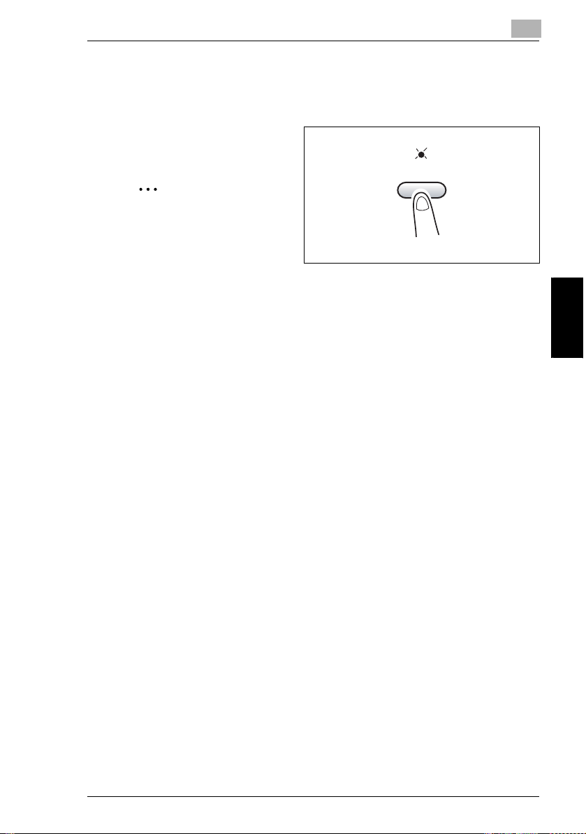
4.6 Finishing Copies
Specifying Sorting
1 Load the originals in the Auto Document Feeder.
2 Press the [Sort] key, and then
check that the indicator lights up.
4
Note
If the Sort indicator is not lit, the
Non-Sort setting is selected.
Sort
3 Make the other necessary settings.
H “Selecting the Paper” on page 4-4
H “Specifying the Zoom Ratio” on page 4-9
H “Adjusting the Image Density” on page 4-11
4 Using the 10-Key Pad, enter the number of print to be made, and then press the
[Start] key.
Making Copies Chapter 4
4-15
Page 93

4
4.6 Finishing Copies
Making Copies Chapter 4
4-16
Page 94

5
Faxing
5
Faxing Chapter 5
Page 95

5
This machine is a G3 fax. Faxes can only be sent or received with this machine if
the recipient’s or sender’s machine complies with the G3 standard.
5.1 Dialing
5.1 Dialing
The recipient’s fax number can be dialed using any of the seven different dialing
methods described below.
Using Direct Dialing to communicate with Overseas Destinations:
If the country code and destination number are entered after the international
code, you may hear a busy tone during dialing and transmission may not be
possible. In such cases, press the [Redial/Pause] key twice after entering the
international code to insert an approx. -6-second pause, and then enter the rest
of the number. If this still fails to connect the call, perform manual transmission.
(p. 6-4).
To fax by entering the fax number directly using the 10-Key Pad
1 Press the [Fax] key to enter Fax mode.
2 Load the document into the Auto Document Feeder.
3 If necessary, change the “Resolution” setting (p. 5-12).
4 Using the 10-Key Pad, enter the
fax number of the recipient.
Faxing Chapter 5
H F codes (SUB and SID) can
also be entered. Refer to
“Using F codes” on page 6-26.
Have you entered the number correctly?
?
§ The fax number can contain a maximum of 30 digits.
§ The keys that can be used to enter the fax number are: the number keys (0
through 9), , #, Space, and Pause
§ If the [Redial/Pause] key is pressed while entering the fax number, a 3-
second pause is added. A pause appears as “P” in the display.
§ If you wish to change the fax number, press the [No] key, and then enter the
correct number.
5-2
Page 96
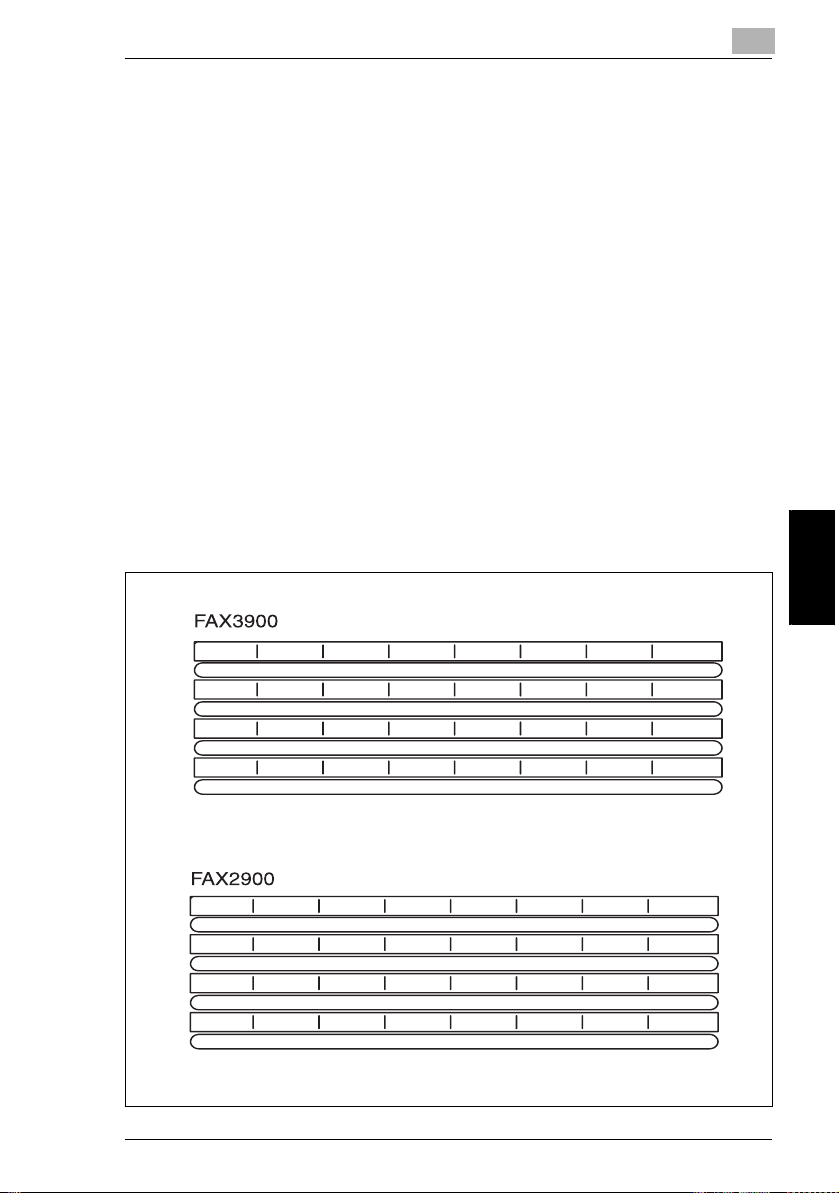
5.1 Dialing
5
§ If the machine is connected to a PBX line and the outside line access
number has been specified in the communication settings (p. 7-69), enter
“#” to dial the outside line access number automatically.
5 Press the [Start] key to begin scanning and sending the fax.
To fax using one-touch dialing
If one-touch dial keys have already been programmed with fax numbers, the fax
number of a recipient can be specified by pressing just the corresponding onetouch dial key.
For details on programming the one-touch dial keys, refer to “Setting Up One-Touch
Dialing (“ONE-TOUCH DIAL” function)” on page 7-27.
1 Press the [Fax] key to enter Fax mode.
2 Load the document into the Auto Document Feeder.
3 If necessary, change the “Resolution” setting (p. 5-12).
4 Press the one-touch dial key programmed with the fax number that you wish to
send the fax to.
01
09
17
25
01/33
09/41
17/49
25/57
02
10
18
26
02/34
10/42
18/50
26/58
03
11
19
27
03/35
11/43
19/51
27/59
04
12
20
28
04/36
12/44
20/52
28/60
05
13
21
29
05/37
13/45
21/53
29/61
06
14
22
30
06/38
14/46
22/54
30/62
07/39
15/47
23/55
31/63
07
15
23
31
08/40
16/48
Faxing Chapter 5
24/56
32/64
08
16
24
32
5-3
Page 97

5
5 Press the [Start] key.
The machine automatically starts
scanning the document and
sending the fax.
5.1 Dialing
Faxing Chapter 5
5-4
Page 98

5.1 Dialing
To fax using speed dialing
If speed dial numbers have already been programmed, the fax number of a
recipient can be specified quickly by entering the corresponding speed dial number.
For details on programming speed dial numbers, refer to “Specifying the Setting for
“SPEED DIAL”” on page 7-31.
5
1 Press the [Fax] key to enter Fax mode.
2 Load the document into the Auto Document Feeder.
3 If necessary, change the “Resolution” setting (p. 5-12).
4 Press the [Speed Dial] key, and
then use the 10-Key Pad to enter
the 3-digit speed dial number.
Has the wrong speed dial
?
number been entered?
§ Press the [No] key, and then
enter the correct number.
5 Press the [Start] key to begin scanning and sending the fax.
Faxing Chapter 5
5-5
Page 99

5
To fax using group dialing
If one-touch dial keys have already been programmed with a group of fax numbers,
the fax numbers of all recipients in the group can be specified by pressing just the
corresponding one-touch dial key.
For details on programming one-touch dial keys with a group of fax numbers, refer
to “Specifying the Setting for “GROUP DIAL”” on page 7-35.
5.1 Dialing
1 Press the [Fax] key to enter Fax mode.
2 Load the document into the Auto Document Feeder.
3 If necessary, change the “Resolution” setting (p. 5-12).
4 Press the one-touch dial key
programmed with the group of fax
numbers that you wish to send the
fax to.
5 Press the [Start] key.
The machine automatically starts
scanning the document and
Faxing Chapter 5
sending the fax.
5-6
Page 100

5.1 Dialing
r
To fax using chain dialing
Faxes can be sent to recipients that are specified using any combination of onetouch dial keys, speed dial numbers, direct input using the 10-Key Pad, and the
[Redial] key.
As an example, the following procedure describes how to specify recipients using
one-touch keys, then using the10-Key Pad.
1 Press the [Speaker] key.
Speake
2 Press the desired one-touch key,
and then press the [Start] key.
5
3 After the message “SET DOC.
FACE UP” appears, use the 10Key Pad to enter the recipient’s fax
number.
4 After the message “SET DOC.
FACE UP” appears, load the
document into the Auto Document
Feeder.
5 Press the [Start] key.
Faxing Chapter 5
5-7
 Loading...