

Page 1

FrameMaker Ver.5.5E(PC) COVER [FIELD SERVICE] FOR Di350
98.12.09
Di350 SERVICE MANUAL
[
FIELD SERV ICE
FrameMaker Ver.5.5E(PC) COVER [FIELD SERVICE] FOR Di350
98.12.09
Di350
SERVICE MANUAL
Copyright
1999 MINOLTA Co., Ltd.
Printed in Japan
Use of this manual should
be strictly supervised to
avoid disclosure of
confidential information.
]
FIELD SERVICE
[
]
MINOLTA Co., Ltd.
1171-7991-11 99022300
Page 2
FrameMaker Ver.5.5E(PC) PL Standard Document Ver.03
99.01.27
Safety Precautions for Inspection and Service
When performing inspection and service procedures, observe the following precautions to
prevent accidents and ensure utmost safety.
✽
Depending on the model, some of the precautions given in the following do not apply.
Different markings are used to denote specific meanings as detailed below.
Indicates a potentially hazardous situation which, if not avoided,
WARNING
CAUTION
The following graphic symbols are used to give instructions that need to be observed.
Used to call the service technician’s attention to what is graphically represented
inside the marking (including a warning).
Used to prohibit the service technician’s from doing what is graphically represented inside the marking.
could result in death or serious injury.
Indicates a potentially hazardous situation which, if not avoided,
may result in minor or moderate injury. It may also be used to
alert against unsafe practices.
Used to instruct the service technician’s to do what is graphically represented
inside the marking.
WARNING
1. Always observe precautions.
•
Parts requiring special attention in this product will include a label containing the
mark shown on the left plus precautionary notes. Be sure to observe the precautions.
•
Be sure to observe the “Safety Infor mation” given in the Operator’s Manual.
2. Before starting the procedures, be sure to unplug the power cord.
•
This product contains a high-voltage unit and a circuit with a large current
capacity that may cause an electric shock or burn.
•
The product also contains parts that can jerk suddenly and cause injury.
•
If this product uses a laser, laser beam leakage may cause eye damage or
blindness.
3. Use the specified parts.
•
For replacement parts, always use the genuine parts specified in the manufacturer’s parts manual. Installing a wrong or unauthor ized part could cause
dielectric breakdown, overload, or undermine safety devices resulting in possible electric shock or fire.
•
Replace a blown electrical fuse or thermal fuse with its corresponding genuine
part specified in the manufacturer’s parts manual. Installing a fuse of a different
make or rating could lead to a possible fire. If a thermal fuse blows frequently,
the temperature control system may have a problem and action must be taken
to eliminate the cause of the problem.
P-1
Page 3

FrameMaker Ver.5.5E(PC) PL Standard Document Ver.03
99.01.27
4. Handle the power cord with care and never use a multiple outlet.
•
Do not break, crush or otherwise damage the power cord. Placing a heavy
object on the power cord, or pulling or bending it may damage it, resulting in a
possible fire or electric shock.
•
Do not use a multiple outlet to which any other appliance or machine is connected.
•
Be sure the power outlet meets or exceeds the specified capacity.
5. Be careful with the high-voltage parts.
•
A part marked with the symbol shown on the left carries a high voltage. Touching it could result in an electric shock or burn. Be sure to unplug the power cord
before servicing this part or the parts near it.
6. Do not work with wet hands.
•
Do not unplug or plug in the power cord, or perform any kind of service or
inspection with wet hands. Doing so could result in an electric shock.
7. Do not touch a high-temperature part.
•
A part marked with the symbol shown on the left and other parts such as the
exposure lamp and fusing roller can be very hot while the machine is energized.
Touching them may result in a burn.
•
Wait until these parts have cooled down before replacing them or any surrounding parts.
8. Maintain a grounded connection at all times. (This item may not apply in the USA.)
•
Be sure to connect the ground wire to the ground terminal even when performing an inspection or repair. Without proper grounding, electrical leakage could
result in an electric shock or fire.
•
Never connect the ground wire to a gas pipe, water pipe, telephone ground wire,
or a lightning conductor.
9. Do not remodel the product.
•
Modifying this product in a manner not authorized by the manufacturer may
result in a fire or electric shock. If this product uses a laser, laser beam leakage
may cause eye damage or blindness.
10. Restore all parts and harnesses to their original positions.
•
To promote safety and prevent product damage, make sure the harnesses are
returned to their original positions and properly secured in their clamps and saddles in order to avoid hot parts, high-voltage parts, sharp edges, or being
crushed.
•
To promote safety, make sure that all tubing and other insulating materials are
returned to their original positions. Make sure that floating components mounted
on the circuit boards are at their correct distance and position off the boards.
P-2
Page 4

FrameMaker Ver.5.5E(PC) PL Standard Document Ver.03
99.01.27
CAUTION
1. Precautions for Service Jobs
•
A toothed washer and spring washer, if used originally, must be reinstalled.
Omitting them may result in contact failure which could cause an electric shock
or fire.
•
When reassembling parts, make sure that the correct screws (size, type) are
used in the correct places. Using the wrong screw could lead to stripped
threads, poorly secured parts, poor insulating or grounding, and result in a malfunction, electric shock or injury.
•
Take great care to avoid personal injury from possible burrs and sharp edges on
the parts, frames and chassis of the product.
•
When moving the product or removing an option, use care not to injure your
back or allow your hands to be caught in mechanisms.
2. Precautions for Servicing with Covers and Parts Removed
•
Wherever feasible, keep all parts and covers mounted when energizing the
product.
•
If energizing the product with a cover removed is absolutely unavoidable, do not
touch any exposed live parts and use care not to allow your clothing to be
caught in the moving parts. Never leave a product in this condition unattended.
•
Never place disassembled parts or a container of liquid on the product. Parts
falling into, or the liquid spilling inside, the mechanism could result in an electric
shock or fire.
•
Never use a flammable spray near the product. This could result in a fire.
•
Make sure the power cord is unplugged before removing or installing circuit
boards or plugging in or unplugging connectors.
•
Always use the interlock switch actuating jig to actuate an interlock switch when
a cover is opened or removed. The use of folded paper or some other object
may damage the interlock switch mechanism, possibly resulting in an electric
shock, injury or blindness.
3. Precautions for the Working Environment
•
The product must be placed on a flat, level surface that is stable and secure.
•
Never place this product or its parts on an unsteady or tilting workbench when
servicing.
•
Provide good ventilation at regular intervals if a service job must be done in a
confined space for a long period of time.
•
Avoid dusty locations and places exposed to oil or steam.
•
Avoid working positions that may block the ventilation ports of the product.
4. Precautions for Handling Batteries
•
Replace a rundown battery with the same type as specified in the manufacturer’s parts manual.
•
Before installing a new battery, make sure of the correct polarity of the installation or the battery could burst.
•
Dispose of used batteries according to the local regulations. Nev er dispose of
them at the user’s premises or attempt to try to discharge one.
P-3
Page 5
FrameMaker Ver.5.5E(PC) PL Standard Document Ver.03
99.01.27
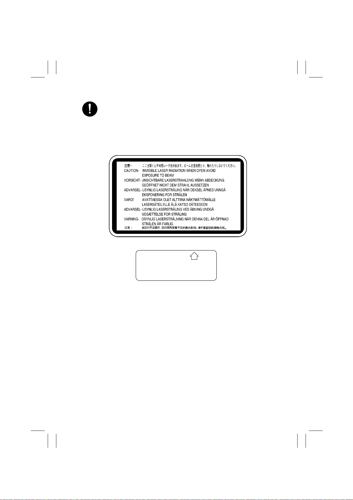
5. Precautions for the Laser Beam (Only for Products Employing a Laser)
•
Removing the cover marked with the follo wing caution label could lead to possible exposure to the laser beam, resulting in eye damage or blindness. Be sure
to unplug the power cord before removing this cover.
•
If removing this cover while the power is ON is una voidable, be sure to wear protective laser goggles that meet specifications.
•
Make sure that no one enters the room when the machine is in this condition.
•
When handling the laser unit, observe the “Precautions for Handling Laser
Equipment.”
.
DANGER
Invisible laser radiation when open.
AVOID DIRECT EXPOSURE
TO BEAM
0947-7127-01
1144D270AA
1167P001AA
P-4
Page 6

FrameMaker Ver.5.5E(PC) PL Standard Document Ver.03
99.01.27
Other Precautions
•
To reassemble the product, reverse the order of disassembly unless otherwise specified.
•
While the product is energized, do not unplug or plug connectors into the circuit boards
or harnesses.
•
The magnet roller generates a strong magnetic field. Do not bring it near a watch, floppy
disk, magnetic card, or CRT tube.
•
An air gun and vacuum cleaner generates a strong electrostatic charge that can destroy
the ATDC sensor and other sensors. Before cleaning a component with one of these
devices, be sure to remove all the sensors. Otherwise, use a blower brush and cloth
when cleaning parts.
•
When handling circuit boards with MOS ICs, observe the “INSTRUCTIONS FOR HANDLING THE PWBs WITH MOS ICs” (applicable only to the products using MOS ICs).
•
The PC Drum is a very delicate component. Observe the precautions given in “HANDLING OF THE PC DRUM” because mishandling may result in serious image problems.
•
Note that replacement of a circuit board may call for readjustments or resetting of particular items, or software installation.
•
After completing a service job, perfor m a safety check. Make sure that all parts, wiring
and screws are returned to their original positions.
•
Check the area surrounding the service site for any signs of damage, wear or need of
repair.
•
Do not pull out the toner hopper while the toner bottle is turning. This could result in a
damaged hopper motor or locking mechanism.
•
If the product is to be run with the front door open, make sure that the toner hopper is in
the locked position.
P-5
Page 7

FrameMaker Ver.5.5E(PC) PL Standard Document Ver.03
99.01.27
Used Batteries Precautions
ALL Areas
Danger of explosion if battery is incorrectly replaced.
Replace only with the same or equivalent type recommended by the manufacturer.
Dispose of used batteries according to the manufacturer’s instructions.
Germany
Explosionsgefahr bei unsachgemäßem Austausch der Batterie.
Ersatz nur durch denselben oder einen vom Hersteller empfohlenen ähnlichen Typ.
Entsorgung gebrauchter Batterien nach Angaben des Herstellers.
France
Ily a danger d’explosion s’ily a remplacement incorrec de la batterie.
Remplacer uniquement avec une batterie du meme type ou d’un type équivalent recommande par le constructueur.
Mettre au rebut les batteries usageés conformément aux instructions du fabricant.
Denmark
Lithiumbatteri - Eksplosionsfare ved fejlagtig håndtering Udskiftning må kun ske med batteri af samme fabrikat og type.
Levér det brugte batteri tilbage til leverandøren.
Norway
Eksplosjonsfare ved feilaktig skifte av batteri.
Benytt samme batteritype eller en tilsvarende type anbefalt av apparatfabrikanten.
Brukte batterier kasseres i henhold til fabrikantens instruksjoner.
CAUTION
VORSICHT!
ATTENTION
ADVARSEL!
ADVARSEL
Sweden
Explosionsfara vid felaktigt batteribyte.
Använd samma batterityp eller en ekvivalent typ som rekommenderas av apparattillverkaren.
Kassera använt batteri enligt fabrikantens instruktion.
Finland
Paristo voi räjähtää, los se on virheellisesti asennettu.
Vaihda paristo ainoastaan laitevalmistajan suosittelemaan tyyppiin. Hävitä Käytetty paristo
valmistajan ohjeiden mukaisesti.
VARNING
VAROlTUS
P-6
Page 8

FrameMaker Ver.5.5(PC) Di350/Di350f
98.12.09
INDEX (FIELD SERVICE)
DIS/REASSEMBLY,
ADJUSTMENT
SWITCHES ON PWBs,
TECH. REP. SETTINGS
TROUBLESHOOTING
Page 9

Page 10

FrameMaker Ver.5.5E(PC) Di350 DIS/REASSEMBLY, ADJUSTMENT
98.12.09
Di350
DIS/REASSEMBLY,
ADJUSTMENT
18605
Page 11

Page 12

FrameMaker Ver.5.5E(PC) Di350 DIS/REASSEMBLY, ADJUSTMENT
98.12.09
CONTENTS
1. SERVICE INSTRUCTIONS .............................................................................D-1
1-1. IDENTIFICATION OF FUSES AND CIRCUIT BREAKER S ....................D-1
1-2. PRECAUTIONS FOR HANDLING THE LASER EQUIPMENT ...............D-1
1-3. INSTRUCTIONS FOR HANDLING THE PWBs WITH MOS ICs ............. D-2
1-4. HANDLING OF THE IMAGING CARTRIDGE ............................ .............D-2
1-5. PARTS WHICH MUST NOT BE TOUCHED ...........................................D-3
(1) Red painted Screws ........................................................................D-3
(2) Variable Resistors on Board ............................................................D-3
(3) Other Screws ...................................................................................D-3
2. DISASSEMBLY/REASSEMBLY ...................................................................... D-4
2-1. DOORS, COVERS, AND EXTERIOR PARTS: IDENTIFICATION AND
REMOVAL PROCEDURES .....................................................................D-4
2-2. REMOVAL OF CIRCUIT BOARDS AND OTHER ELECTRICAL
COMPOMENTS .......................................................................................D-7
2-3. PAPER TAKE-UP/TRANSPORT SECTION ............................................D-10
(1) Replacement of the Paper Take-Up Roll ......................................... D-10
(2) Replacement of the Paper Dust Remover .......................................D-10
(3) Cleaning of the Paper Dust Remover ..............................................D-11
(4) Cleaning of the Side Cover ..............................................................D-11
(5) Cleaning of the Duplex Unit Cover ..................................................D-11
2-4. OPTICAL SECTION ............................. ...................................................D-12
(1) Removal of the IR Unit ....................................................................D-12
(2) Removal of the PH Unit ...................................................................D-13
(3) Removal of the CCD Unit ................................................................D-15
(4) Cleaning of the Scanner Rails/Bushings ...................................... ...D-15
(5) Cleaning of the Mirrors ....................................................................D-16
(6) Cleaning of the Lens ........................................................................D-16
(7) Cleaning of the Original Glass .......................................... ...............D-16
(8) Removal of the Scanner ..................................................................D-16
(9) Removal of the Scanner Drive Cables ............................................D-18
(10) Winding of the Scanner Drive Cables ..............................................D-19
2-5. IMAGE TRANSFER SECTION ................................................................D-23
(1) Removal of the Image Transfer Roller .............................................D-23
(2) Cleaning of the Comb Electrode ......................................................D-23
(3) Cleaning of the Pre-Image Transfer Guide Plate ........................... .D-24
(4) Replacement of the Ozone Filter .....................................................D-24
2-6. DEVELOPING SECTION ............................. ...........................................D-25
(1) Removal of the Imaging Cartridge ...................................................D-25
2-7. FUSING SECTION ..................................................................................D-26
(1) Removal of the Fusing Unit ............................................................. D-26
(2) Removal of the Fusing Roller Heater Lamp, Fusing Right Roller,
Fusing Left Roller, Fusing Roller Thermistor, Fusing Roller
Thermostat, and Fusing Roller Heater Lamp Fuse .................. .......D-26
3. ADJUSTMENT .................................................................................................D-29
3-1. ADJUSTMENT JIGS AND TOOLS USED ...............................................D-29
3-2. ADJUSTMENT REQUIREMENT LIST ....................................................D-29
i
Page 13

FrameMaker Ver.5.5E(PC) Di350 DIS/REASSEMBLY, ADJUSTMENT
98.12.09
3-3. ADJUSTMENT OF BELT TENSION ........................................................D-30
3-4. TEST PRINT .................... ................................................................. .......D-31
3-5. ELECTRICAL/IMAGE ADJUST MENT .......................................... ...........D-32
(1) Touch Panel Adj. .............................. ...............................................D-32
(2) Original Size Detecting Sensor Adjustment (F7-1) ..........................D-33
(3) Loop Adjustment ................................................................. .............D-34
(4) Edge Erase ......................................................................................D-35
(5) Registration (CD) (Printer) ...............................................................D-38
(6) Registration (FD) (Printer) ........ ......................... ......................... .....D-40
(7) Registration (IR) ............ ....................... ...........................................D-42
(8) Zoom Adjust (IR) .............................................................................D-46
(9) IR-Erasure Width .............................................................................D-50
3-6. OTHER ADJUSTMENTS .........................................................................D-51
4. MISCELLANEOUS ..........................................................................................D-53
4-1. INSTALLATION OF THE KEY COUNTER SOCKET (OPTION) ............. D-53
4-2. REMOUNTING THE EEPROM (IC3A) ......... ...........................................D-54
ii
Page 14
FrameMaker Ver.5.5E(PC) Di350 DIS/REASSEMBLY, ADJUSTMENT
98.12.09
1 SERVICE INSTRUCTIONS
1-1. IDENTIFICATION OF FUSES AND CIRCUIT BREAKERS
125V 3.15A
125V 5A
Master Board
PWB-A125V 3A (F1)
125V 3A (F2)
250V 1A (F3)
250V 1A (F4)
Power Supply Unit 1
PU1 125V 10A (F1)
125V 15A (F2)
250V 3.15A (F3)
250V 3.15A (F4)
Power Supply Unit 2
PU2 125V 5A
Fusing Roller
Heater Lamp Fuse
TF1 125V 15A
Fusing Roller
Thermostat
TS1 250V 10A
1171D016AC
1-2. PRECAUTIONS FOR HANDLING THE LASER EQUIPMENT
•
The laser used in this copier is a semiconductor laser having the following specifications.
Max. power: 5mW
Output wavelength: 770~810nm
•
When laser protective goggles are to be used, select ones with a lens conforming to the
above specifications.
•
When a disassembly job needs to be performed in the laser beam path, such as when
working around the printerhead and PC Drum, be sure first to turn the copier OFF.
•
If the job requires that the copier be left ON, take off your watch and ring and wear laser
protective goggles.
•
A highly reflective tool can be dangerous if it is brought into the laser beam path. Use
utmost care when handling tools on the user’s premises.
•
The printerhead is not maintainable in the field. It is to be replaced as an assembly
including the control board. Never, therefore, attempt to remove the laser diode or adjust
trimmers on the control board.
D-1
Page 15

FrameMaker Ver.5.5E(PC) Di350 DIS/REASSEMBLY, ADJUSTMENT
98.12.09
1-3. INSTRUCTIONS FOR HANDLING THE PWBs WITH MOS ICs
The following precautions must be observed when handling P.W. Boards with MOS
(Metal Oxide Semiconductor) ICs.
During Transportation/Storage:
•
During transportation or when in storage, new P.W. Boards must not be indiscriminately
removed from their protective conductive bags.
•
Do not store or place P.W. Boards in a location exposed to direct sunlight.
•
When it becomes absolutely necessary to remove a Board from its conductive bag or
case, always place it on its conductive mat in an area as free as possible from static electricity.
•
Do not touch the pins of the ICs with your bare hands.
During Replacement:
•
Before unplugging connectors from the P.W. Boards, make sure that the power cord has
been unplugged from the outlet.
•
When removing a Board from its conductive bag or conductive case, do not touch the
pins of the ICs or the printed pattern. Place it in position by holding only the edges of the
Board.
•
Before plugging connectors into the Board, make sure that the power cord has been
unplugged from the power outlet.
During Inspection:
•
Avoid checking the IC directly with a multimeter; use connectors on the Board.
•
Never create a closed circuit across IC pins with a metal tool.
•
When it is absolutely necessary to touch the ICs and other electrical components on the
PW Board, be sure to ground your body.
1-4. HANDLING OF THE IMAGING CARTRIDGE
During Transportation/Storage:
•
Use the specified carton whenever moving or storing the Imaging Cartridge.
•
The storage temperature is in the range between –20°C and +40°C.
•
In summer, avoid leaving the Imaging Cartridge in a car for a long time.
Handling:
•
Ensure that the correct Imaging Cartridge is used.
•
Store the Imaging Cartridge in a site that is not exposed to direct sunlight.
Precautionary Information on the PC Drum Inside the Imaging Cartridge:
•
The PC Drum exhibits greatest light fatigue after being exposed to strong light over an
extended period of time. Never, therefore, expose it to direct sunlight.
•
Use care not to contaminate the surface of the PC Drum with oil-base solvent, fingerprints, and other foreign matter.
•
Do not scratch the surface of the PC Drum.
•
Do not apply chemicals to the surface of the PC Drum.
•
Do not attempt to wipe clean the surface of the PC Drum.
D-2
Page 16
FrameMaker Ver.5.5E(PC) Di350 DIS/REASSEMBLY, ADJUSTMENT
98.12.09
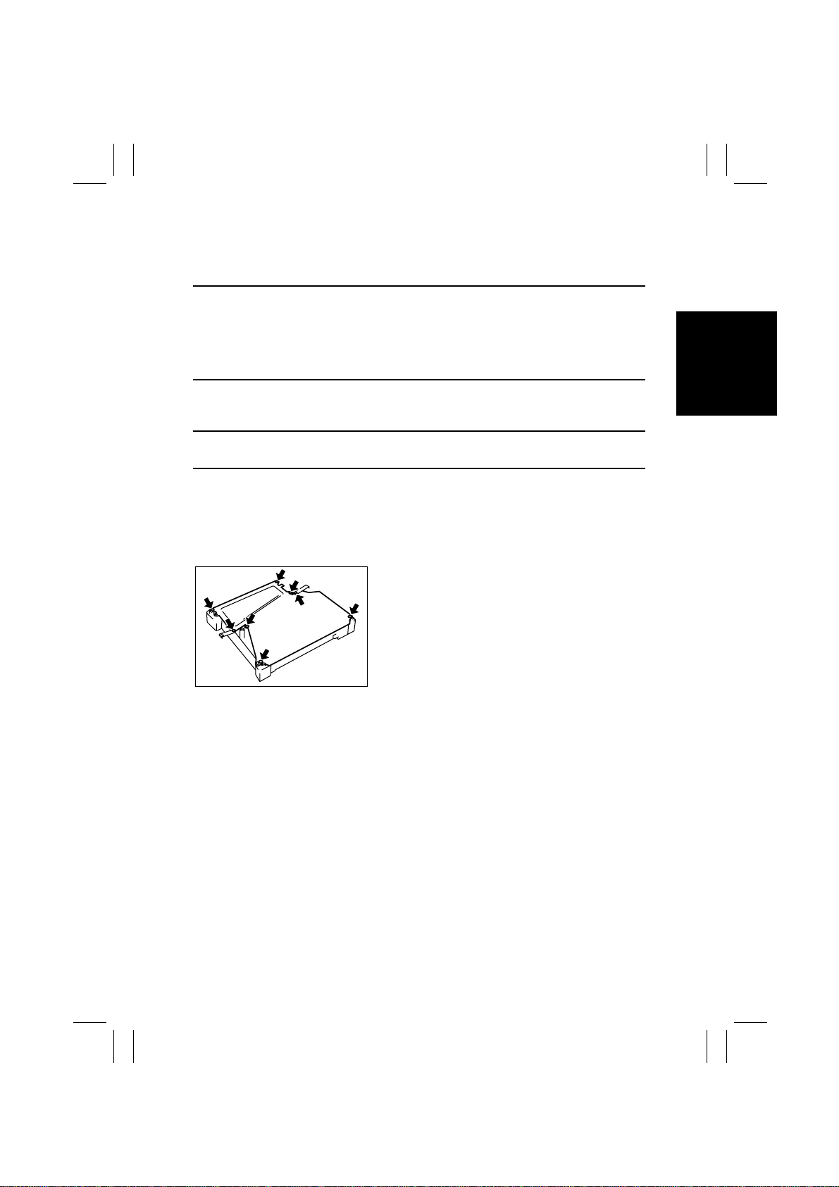
1-5. PARTS WHICH MUST NOT BE TOUCHED
(1) Red painted Screws
Purpose of Application of Red Paint
Red painted screws show that the assembly or unit secured can only be adjusted or set at
the factory and should not be readjusted, set, or removed in the field.
Note that when two or more screws are used on the part in questions, only one representative screw may be marked with red paint.
(2) Variable Resistors on Board
Do not turn the variable resistors on boards for which no adjusting instructions are given in
“ADJUSTMENT.”
(3) Other Screws
Although not marked with red paint, the following screws must not be loosened or readjusted.
8 screws on the PH Unit Cover
1167D002AB
D-3
Page 17
FrameMaker Ver.5.5E(PC) Di350 DIS/REASSEMBLY, ADJUSTMENT
98.12.09
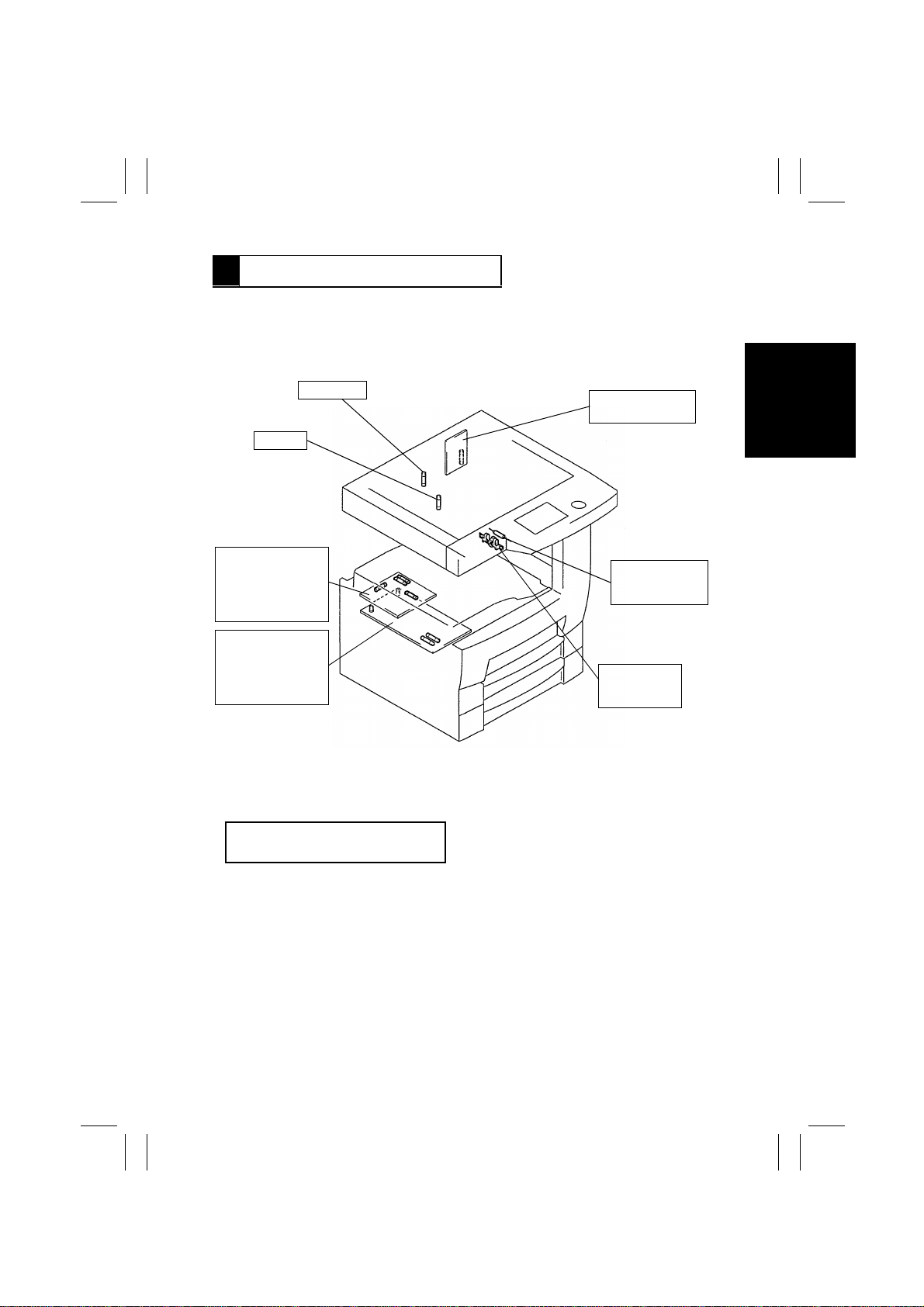
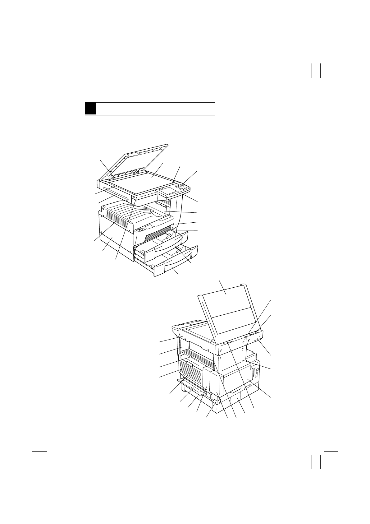
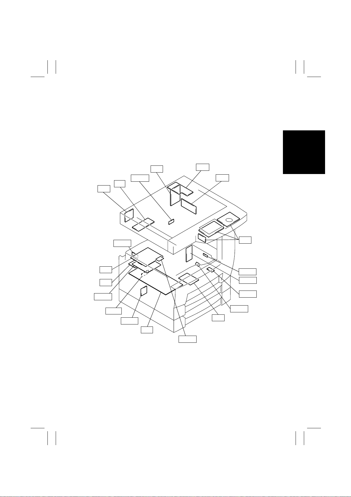
2 DISASSEMBLY/REASSEMBLY
2-1. DOORS, COVERS, AND EXTERIOR PARTS: IDENTIFICATION
AND REMOVAL PROCEDURES
14
1
15
2
13
12
3
4
5
6
7
8
9
1171D017AA
10
11
16
17
18
34
33
32
31
30
29
D-4
28
27
26
19
20
21
22
23
2425
1171D018AB
Page 18
FrameMaker Ver.5.5E(PC) Di350 DIS/REASSEMBLY, ADJUSTMENT
98.12.09
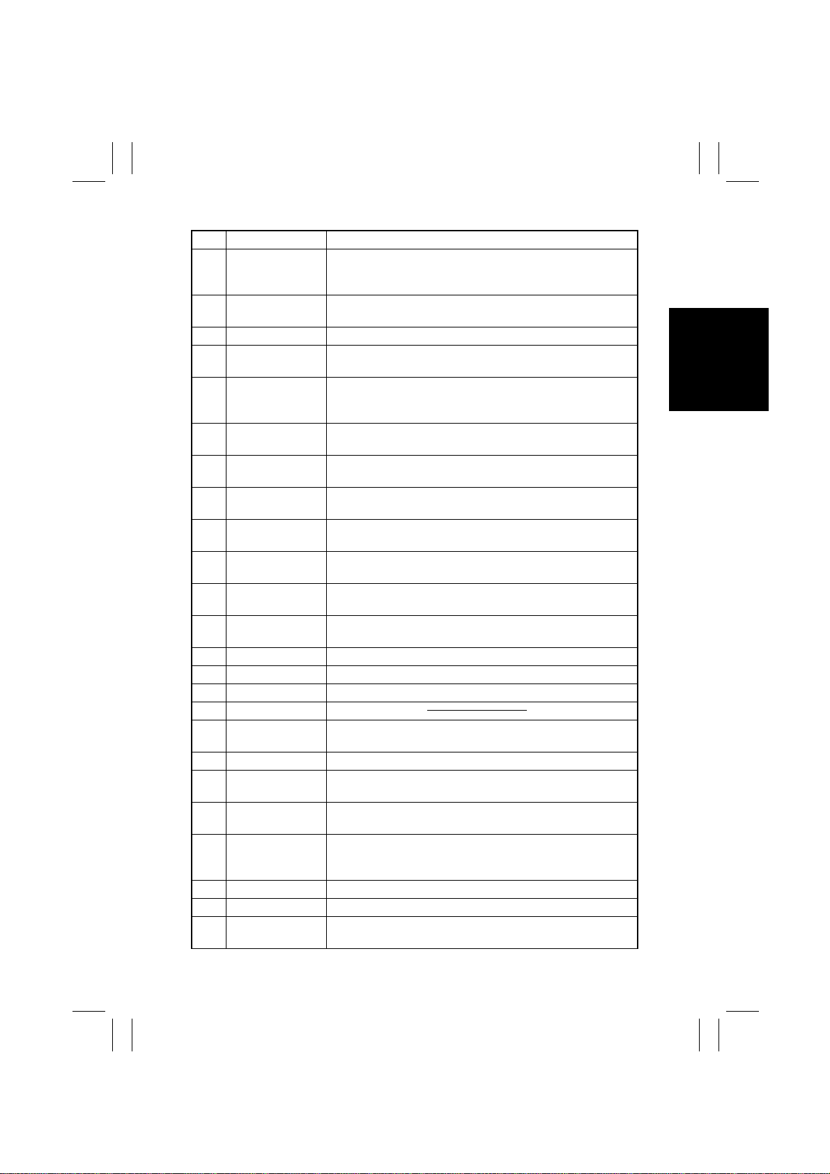
No. Part Name Removal Procedure
1 ADF Glass Assy. Remove No. 2, 4. → Remove two holding brackets. →
2 Rear Holding
Bracket
3 Original Glass Remove No. 4. → Remove two holding brackets.
4 Front Holding
Bracket
5 Control Panel Remove No. 8. → Remove No. 6. → Remove No. 4. →
6 Front Upper Cover Remove No. 8. → Remove No. 12. → Remove six screws that
7 Exit Lower Cover Remove No. 32. → Remove No. 24. → Unhook the two tabs of
8 Front Cover Slide out No. 10. → Open No. 25. → Remove three screws
9 LED Cover Slide out No. 10. → Remove one screw that secure the LED
10 MP Cassette Slide out the MP Cassette. → Pushing the tab on the right rail,
11 500-Sheet
Cassette
12 Upper Front Left
Cover
13 Left Cover Remove six screws that secure the Left Cover.
14 Upper Cover Remove two screws that secure the Upper Cover.
15 Left IR Cover Remove two screws that secure the Left IR Cover.
16 Original Cover
17 Rear Right IR
Cover
18 Left Hinge Cover Remove one screw that secure the Left Hinge Cover.
19 Rear Left IR Cover Remove No. 17. → Remove two screws that secure the Rear
20 Rear Upper Cover Remove No. 21. → Remove No. 17. → Remove No. 19. →
21 Rear Lower Cover Remove No. 26. → Remove No. 25. → Open No. 30. → Open
22 Right Hinge Cover Remove one screw that secure the Right Hinge Cover.
23 Connector Cover Remove one screw that secure the Connector Cover.
24 Rear Inside Cover Remove No. 22. → Remove three screws that secure the Rear
Remove two screw caps. → Remove two screws that secure
the ADF Glass Assy.
Remove No. 17, 18. → Remove two screw caps. → Remove
two screws that secure the Rear Holding Bracket.
Remove two screw caps. → Remove two screws that secure
the Front Holding Bracket.
Remove No. 12. → Remove five screws that secure the control
panel and unplug one connector.
secure the Front Upper Cover.
the Exit Lower Cover and remove the Exit Lower Cover.
that secure the Front Cover.
Cover.
pull out the cassette.
Slide out the 500-Sheet Cassette. → Pushing the tabs on both
the right and left rails, pull out the cassette.
Remove No . 4. → Remove two screws that secure the Upper
Front Left Cover.
Remove No . 22. → Remove No. 19. → Remove two screws
that secure the Rear Right IR Cover.
Left IR Cover.
Remove four screws that secure Rear Upper Cover.
No. 32. → Remove five screws that secure the Rear Lower
Cover.
Inside Cover.
D-5
Page 19

FrameMaker Ver.5.5E(PC) Di350 DIS/REASSEMBLY, ADJUSTMENT
98.12.09
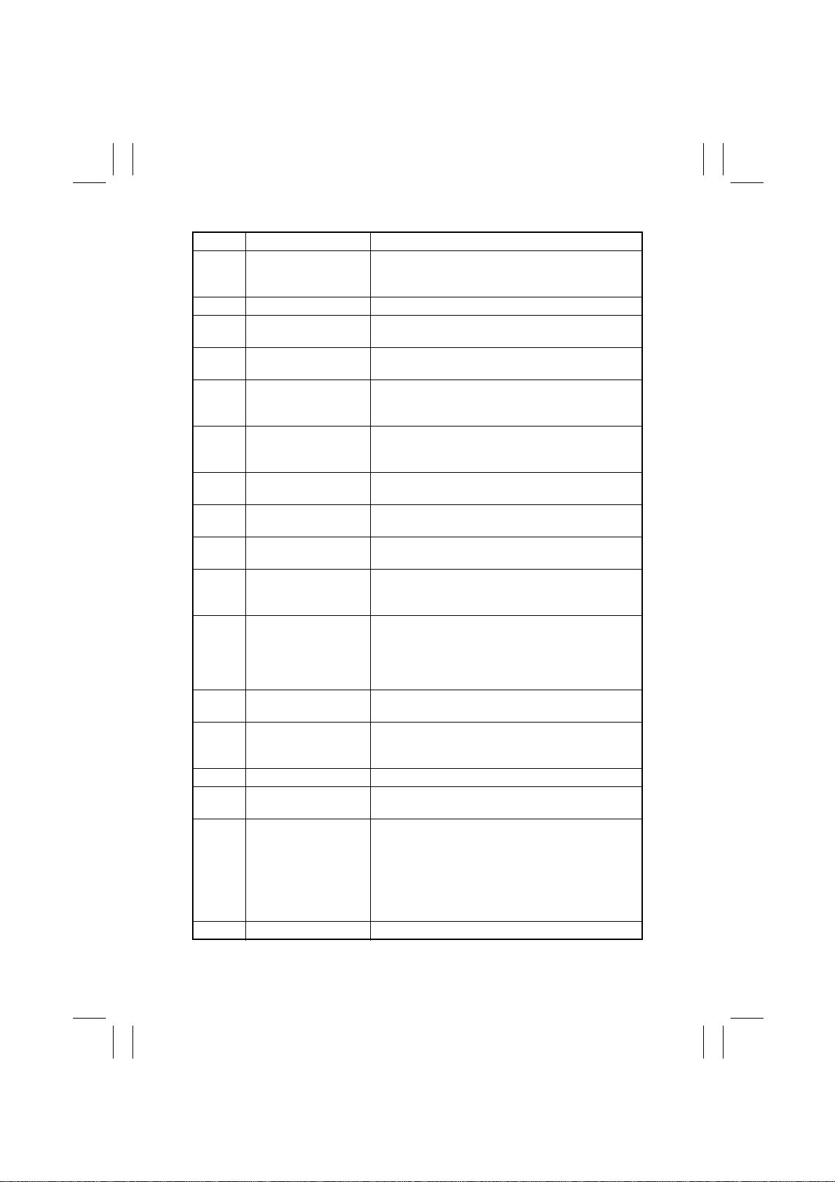
No. Part Name Removal Procedure
25 Toner Bottle Cover Open the Toner Bottle Cover. → Unhook the dowels at four
26 Harness Cover Remove one screw that secure the Harness Cover.
27 Duplex Unit Rear
Cover
28 500-Sheet Cas-
sette Side Cover
29 Manual Bypass
Tray
30 Side Cover
31 Duplex Unit Remove two screws that secure the Duplex Unit.
32 Fusing Unit See D-26.
33 Front Inside Cover Remove No. 8. → Remove No. 32. → Remove two screws that
34 Right IR Cover Remove three screws that secure the Right IR Cover.
places of the Toner Bottle Cover.
Remove No . 31. → Remove two screws that secure the
Duplex Unit Rear Cover.
Open the Side Cover . → Slide the Side Cover to the front and,
at the same time, pull the rear side out of the frame.
Remove No . 26. → Unplug one connector. → Remove three
screws that secure the Manual Bypass Tray.
secure the Front Inside Cover.
D-6
Page 20
FrameMaker Ver.5.5E(PC) Di350 DIS/REASSEMBLY, ADJUSTMENT
98.12.09
2-2. REMOVAL OF CIRCUIT BOARDS AND OTHER ELECTRICAL
COMPOMENTS
•
When removing a circuit board or other electrical component, refer to “PRECAUTIONS
FOR HANDLING THE PWBs” contained in SWITCHES ON PWBs and follow the corresponding removal procedures.
•
The removal procedures given in the following omit the removal of connectors and
screws securing the circuit board support or circuit board.
•
Where it is absolutely necessary to touch the ICs and other electrical components on the
board, be sure to ground your body.
BCR
UN2
UN3
PWB-A
PWB-I
INV
PWB-L
PWB-A
PWB-R
PU1
PU2
HGB
CCD
UN1
PWB-R
PWB-A
PWB-R
PWB-H
HV1
1171D020AE
PWB-N
D-7
Page 21
FrameMaker Ver.5.5E(PC) Di350 DIS/REASSEMBLY, ADJUSTMENT
98.12.09
Symbol P art Name Removal Procedure
PWB-A Master Board Remo ve the Upper Cover. → Remove nine screws
PWB-A Cassette Main Board Remove the Connector Cover. → PWB-A
PWB-A Duplex Main Board Remove the Duplex Unit. → Remove the Duplex Unit
PWB-H Double Feed Detecting
Board
PWB-I Paper Size Detecting
Board
PWB-L PPM Switching Board Remove the Harness Cover. → Remove the Rear
PWB-N RAM Board Remove the Upper Cover. → Remove nine screws
PWB-R Fuser Frame Register
Board
PWB-R Pre-Transfer Guide
Plate Register Board 1
PWB-R Pre-Transfer Guide
Plate Register Board 2
PU1 Power Supply Board 1 Remove the Ha rness Cover. → Remove the Rear
PU2 Power Supply Board 2 Remove the Ha rness Cover. → Remove the Rear
HV1 High Voltage Unit Open the Side Cover. → Remove the Imaging Car-
INV Inverter Board Remove the Original Glass. → INV
BCR BCR Board Remove the Rear Left IR Cover. → Remove three
HGB HGB Board Remove the Original Glass.
CCD CCD Board See D-15.
and the MFB Box Cover. → Remove two screws and
the MFB Box Assy. → PWB-A
Rear Cover. → PWB-A
Slide out the MP Cassette. → Remove one screw and
the PWB-H Mounting Bracket Assy. → PWB-H
Remove the Harness Cover. → Remove the Rear
Cover. → Remove two screws and the PW Board
Cover. → PWB-I
Cover. → Remove one screw and the PWB-L Mounting Bracket Assy. → PWB-L
and the MFB Box Cover. → PWB-N
Remove the Fusing Unit. → Remove the rear lamp
cover. → PWB-R
Remove the Vertical Transport Unit. → Remove two
screws and two ground plates. → PWB-R
Open the Side Cover. → Remove the Imaging Car-
tridge. → Remove one screw and the PW Board
Cover. → PWB-R
Cover. → Remove the Left Cover. → Remove five
screws and the Reinforcement Bracket. → Remove
three screws and the PU1 Mounting Bracket Assy. →
PU1
Cover. → PU2
tridge. → Remove two screws and the HV1 Cover. →
HV1
screws and the Harness Cover. → BCR
→
→
Cover.
Rear Lower Cover.
→
only)
→
and the HGB Mounting Bracket Assy.
Remove the Optical Cover.
→
Remove the Shielding Plate. (U.S.A. and Canada
→
Remove one screw and the Harness Cover.
Unplug nine connectors. → Remove five screws
Remove the Rear Upper Co ver.
Remove the Right IR
→
Remove the
→
HGB
D-8
Page 22

FrameMaker Ver.5.5E(PC) Di350 DIS/REASSEMBLY, ADJUSTMENT
98.12.09
Symbol P art Name Removal Procedure
UN2 MFB Board Remove the Upper Cover. → Remove nine screws
UN3 Polygon Motor Drive
Board
and the MFB Box Cover. → UN2
Remove the PH Unit. → UN3
D-9
Page 23
FrameMaker Ver.5.5E(PC) Di350 DIS/REASSEMBLY, ADJUSTMENT
98.12.09
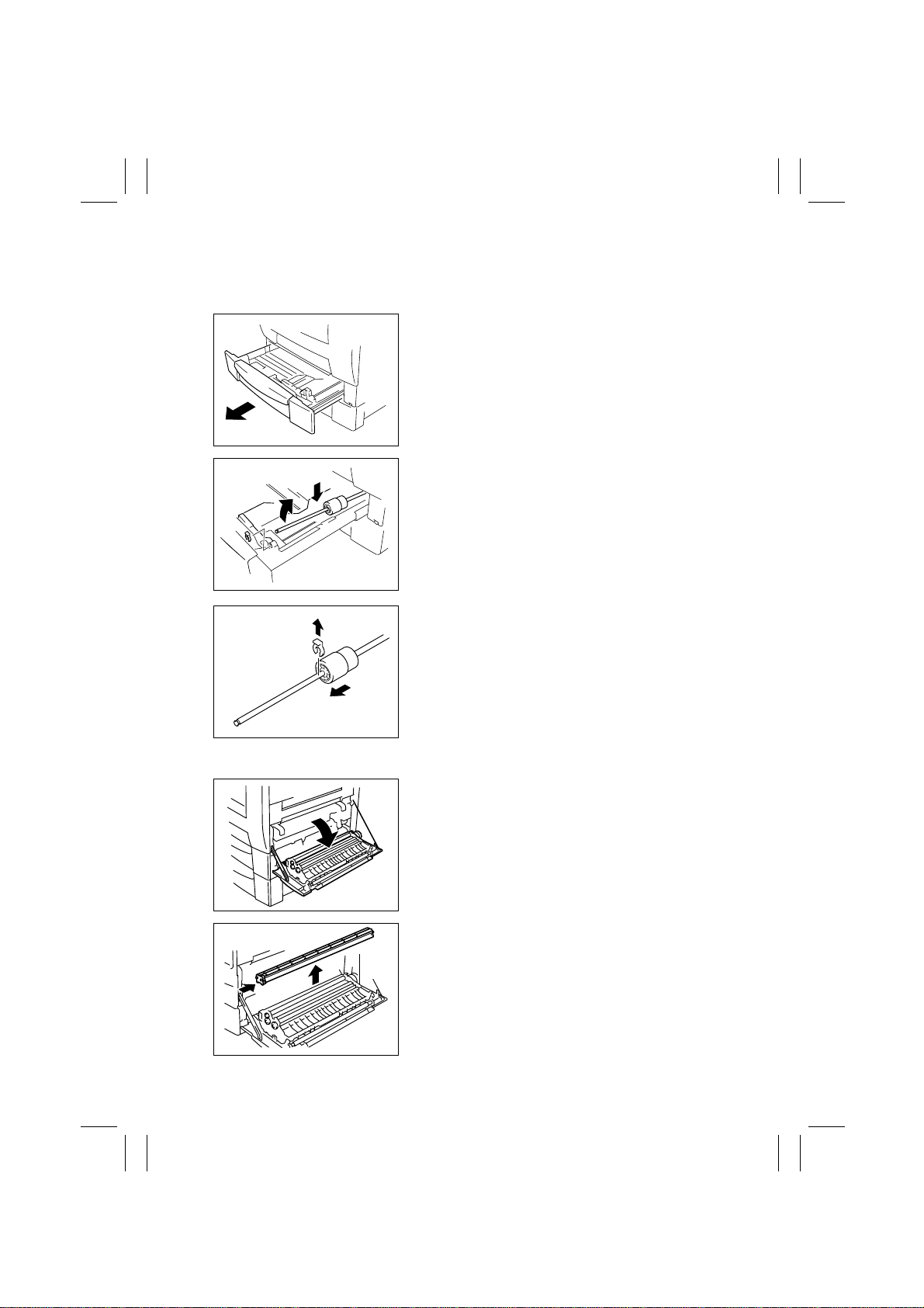
2-3. PAPER TAKE-UP/TRANSPORT SECTION
(1) Replacement of the Paper Take-Up Roll
1. Slide out the MP Cassette.
4108D033AA
2. Lock the Paper Lifting Plate.
3. Snap off one C-clip of the Paper Take-Up Roll
Assy.
4. Slide the Paper Take-Up Roll Assy to the rear so
that it can be pulled off the bushing at the front.
1167D140AA
5. Snap off one C-clip and remove and replace the
Paper Take-Up Roll.
4108D035AA
(2) Replacement of the Paper Dust Remover
1. Open the Side Cover.
1171D021AA
2. Remove the Paper Dust Remover and replace it.
1167D007AB
D-10
Page 24
FrameMaker Ver.5.5E(PC) Di350 DIS/REASSEMBLY, ADJUSTMENT
98.12.09
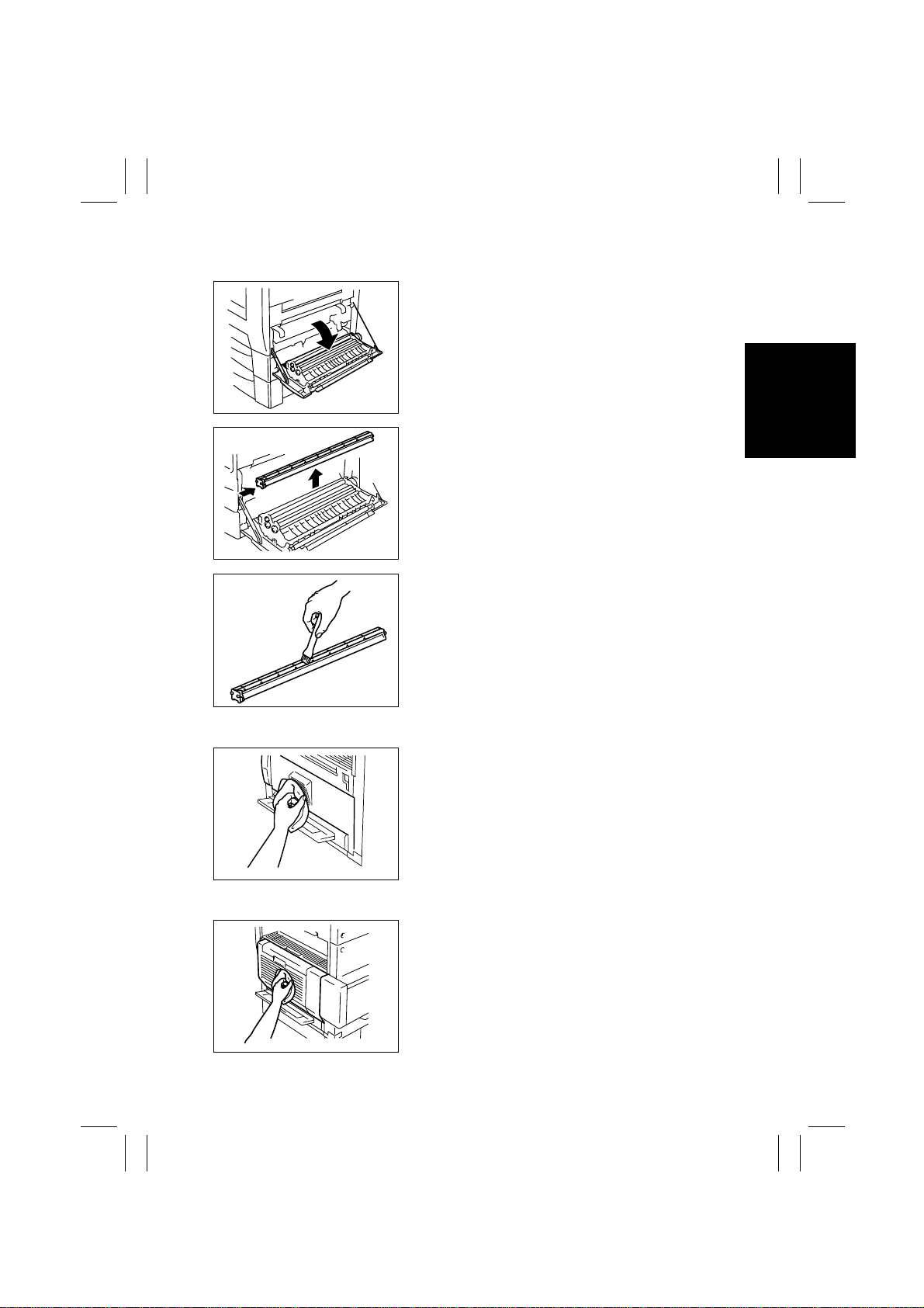
(3) Cleaning of the Paper Dust Remover
1. Open the Side Cover.
1171D021AA
2. Remove the Paper Dust Remover.
1167D007AB
3. Using a brush, whisk dust and dirt off the Paper
Dust Remover.
1167D008AB
(4) Cleaning of the Side Cover
Using a soft cloth dampened with alcohol, wipe the
Side Cover.
1171D052AB
(5) Cleaning of the Duplex Unit Cover
Using a soft cloth dampened with alcohol, wipe the
Duplex Unit Cover.
1171D051AA
D-11
Page 25
FrameMaker Ver.5.5E(PC) Di350 DIS/REASSEMBLY, ADJUSTMENT
98.12.09
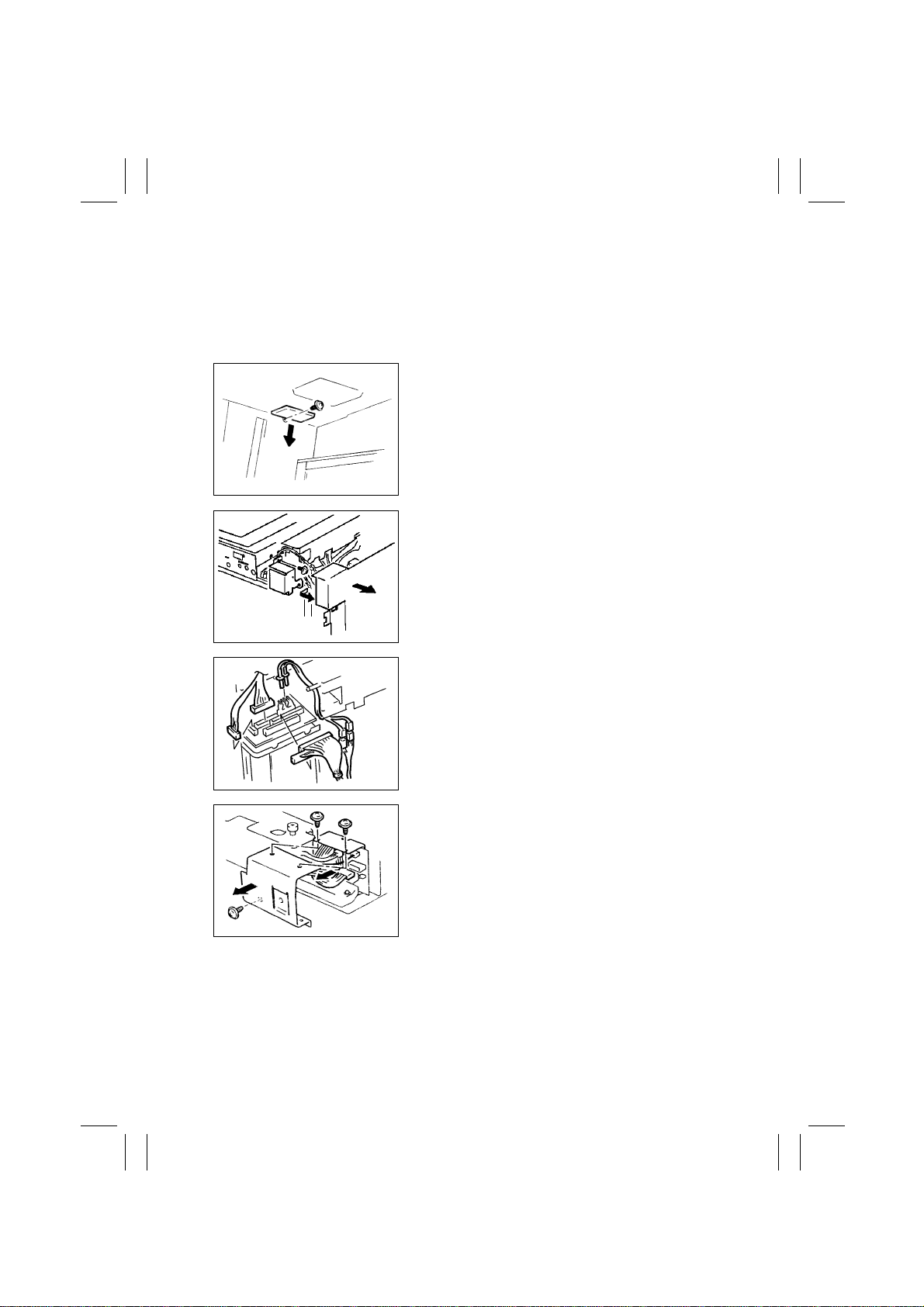
2-4. OPTICAL SECTION
(1) Removal of the IR Unit
1. Remove the Original Cover, Front Holding Brack et, Upper F ront Left Co v er , Front Cover,
Front Upper Cover, Rear Right IR Cover, Rear Left IR Cover, Rear Lower Cover, Rear
Upper Cover, and Front Inside Cover.
2. Remove one screw and the Motor Cover.
1171D054AA
3. Remove the Shielding Plate. (U.S.A. and Canada
only)
4. Remove one screw and the Harness Cover.
1167D149DA
1167D027AC
1167D032AC
5. Unplug eight connectors of the HGB Board.
6. Remove three screws and the Harness Cover.
7. Unplug one connector of the BCR Board.
D-12
Page 26
FrameMaker Ver.5.5E(PC) Di350 DIS/REASSEMBLY, ADJUSTMENT
98.12.09
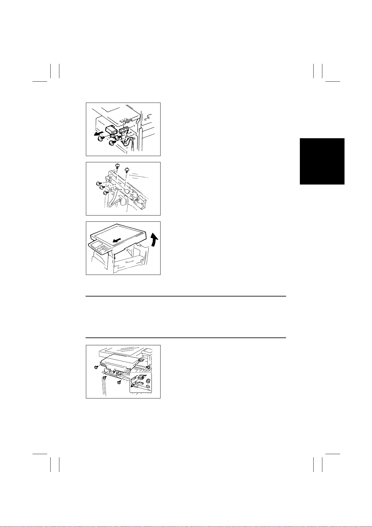
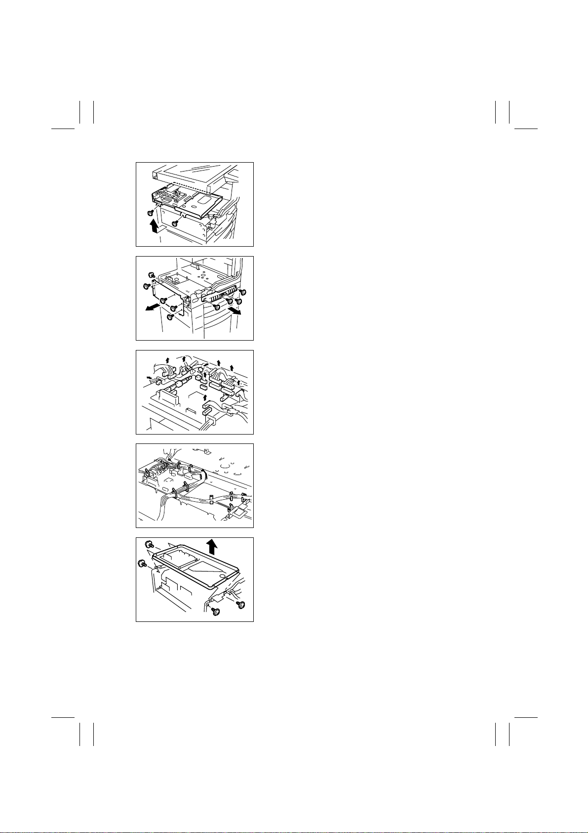
8. Remove one screw and the Total Counter Mounting Bracket Assy.
9. Unplug one connector of the Control Panel.
10. Remove two screws that secure the front end of
the frame.
1167D033AC
11. Remove five scre ws that secure the rear end of the
frame.
1167D059AC
12. Raise the rear end of the IR Unit and pull the unit
out toward front.
1171D053AA
(2) Removal of the PH Unit
NOTES
•
Do not place the PH Unit upside down or subject it to excessive shock.
•
Replace the PH Unit as one unit.
•
NEVER attempt to disassemble or adjust the PH Unit.
•
Whenever the PH Unit has been removed, make the following adjustments:
Edge Erase, Registration (CD, FD) (Printer), Registration (IR).
1. Remove the Upper Cover, Front Cover, Left Cover,
and Rear Cover.
2. Remove four screws and the MFB Box Cover.
3. Unplug five connectors of the MFB Board.
1167D058AE
D-13
Page 27
FrameMaker Ver.5.5E(PC) Di350 DIS/REASSEMBLY, ADJUSTMENT
98.12.09
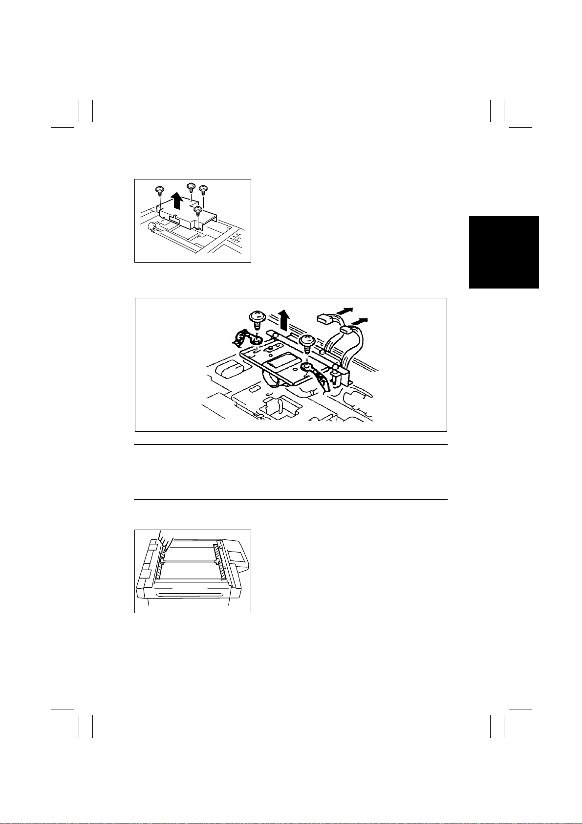
4. Remove two screws and the MFB Box Assy.
1167D028AA
5. Remove five screws and the Reinforcement
Bracket.
6. Remove four screws and the handle.
1167D062AC
7. Unplug all connectors (13) from Master Board
PWB-A.
1167D029AC
1167D030AB
1167D012AA
8. Remove the harness from all cord clamps (12) on
the PH Base Plate.
9. Remove four screws and the PH Unit.
D-14
Page 28
FrameMaker Ver.5.5E(PC) Di350 DIS/REASSEMBLY, ADJUSTMENT
98.12.09
(3) Removal of the CCD Unit
1. Remove the Original Glass.
2. Remove four screws and the Cover.
1167D014AB
3. Unplug two connectors of the CCD Unit.
4. Remove two screws and the CCD Unit.
1171D055AA
NOTES
1. When removing the CCD Unit, remove only those screws and parts that are specified.
(Remove the CCD Unit as one unit.)
2. Whenever the CCD Unit has been replaced, make the following adjustment:
FD of Zoom Adjust (IR).
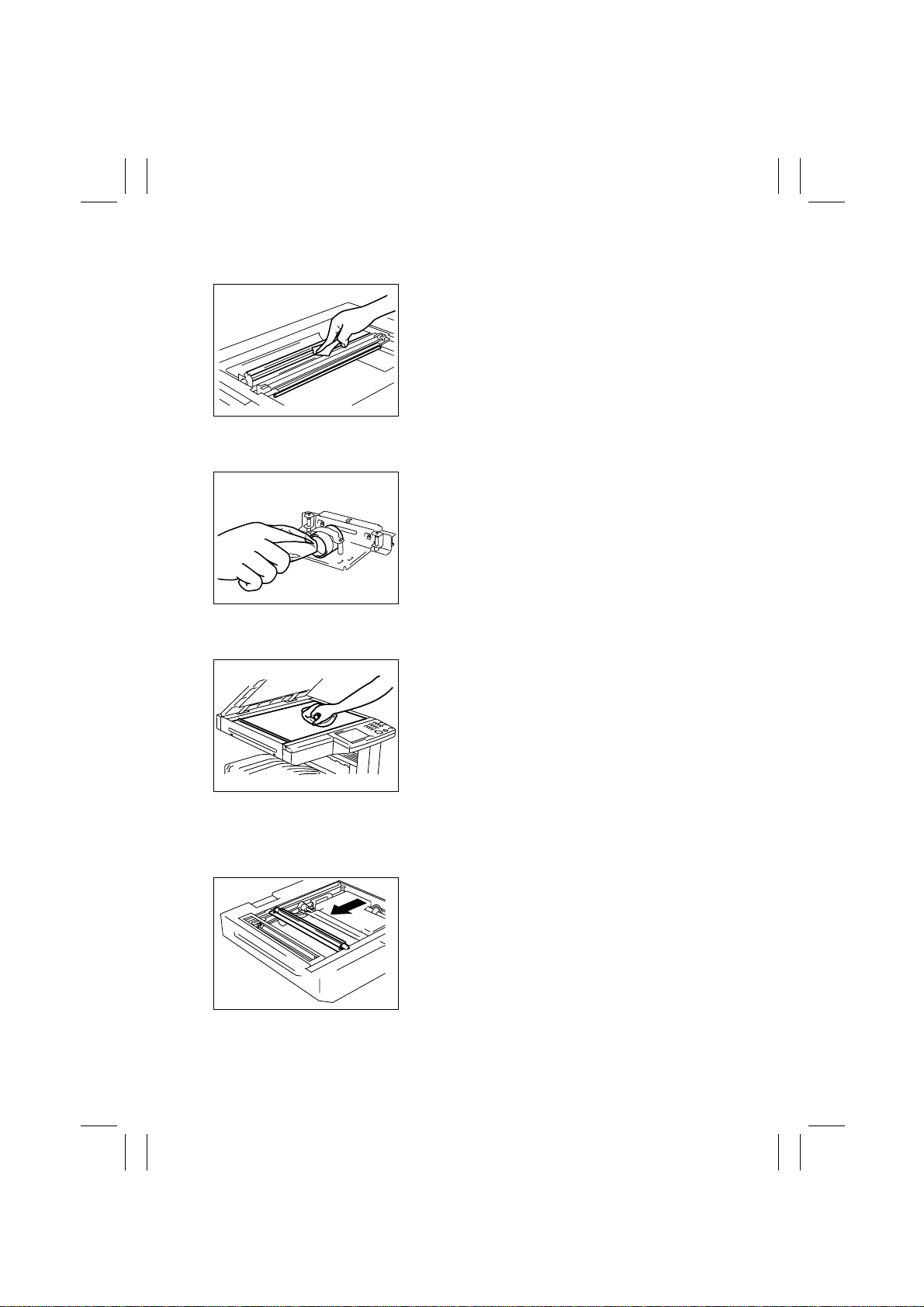
(4) Cleaning of the Scanner Rails/Bushings
1. Remove the Original Glass.
2. Using a soft cloth, wipe clean the Scanner Rails
and Bushings.
1167D016AB
D-15
Page 29
FrameMaker Ver.5.5E(PC) Di350 DIS/REASSEMBLY, ADJUSTMENT
98.12.09
(5) Cleaning of the Mirrors
1. Remove the Original Glass.
2. Wipe clean the Mirrors with a soft cloth.
1167D017AC
(6) Cleaning of the Lens
1. Remove the CCD Unit.
2. Wipe clean the Lens with a soft cloth.
1167D018AB
(7) Cleaning of the Original Glass
Wipe clean the Original Glass with a soft cloth.
1171D050AA
(8) Removal of the Scanner
1. Remove the Original Glass.
2. Remove the Rear Holding Bracket.
3. Slide the Scanner to the position shown.
1167D039AC
D-16
Page 30
FrameMaker Ver.5.5E(PC) Di350 DIS/REASSEMBLY, ADJUSTMENT
98.12.09
4. Remove one screw and unplug the connector of
the Exposure Lamp.
5. Remove the flat cable of the Exposure Lamp.
1167D037AC
6. Remove one screw and the Lamp Fixing Bracket.
1167D035AD
Rear
7. Slide the Exposure Lamp to the front and remove
it.
Front
1167D036AA
8. Remove two screws and the Scanner.
1167D049AB
D-17
Page 31

FrameMaker Ver.5.5E(PC) Di350 DIS/REASSEMBLY, ADJUSTMENT
98.12.09
(9) Removal of the Scanner Drive Cables
1. Remove the Original Glass and ADF Glass Assy.
2. Remove the Left IR Cover.
3. Remove the Scanner.
4. Unhook the spring of the cable on the hook side,
one each at the front and in the rear.
1167D044AB
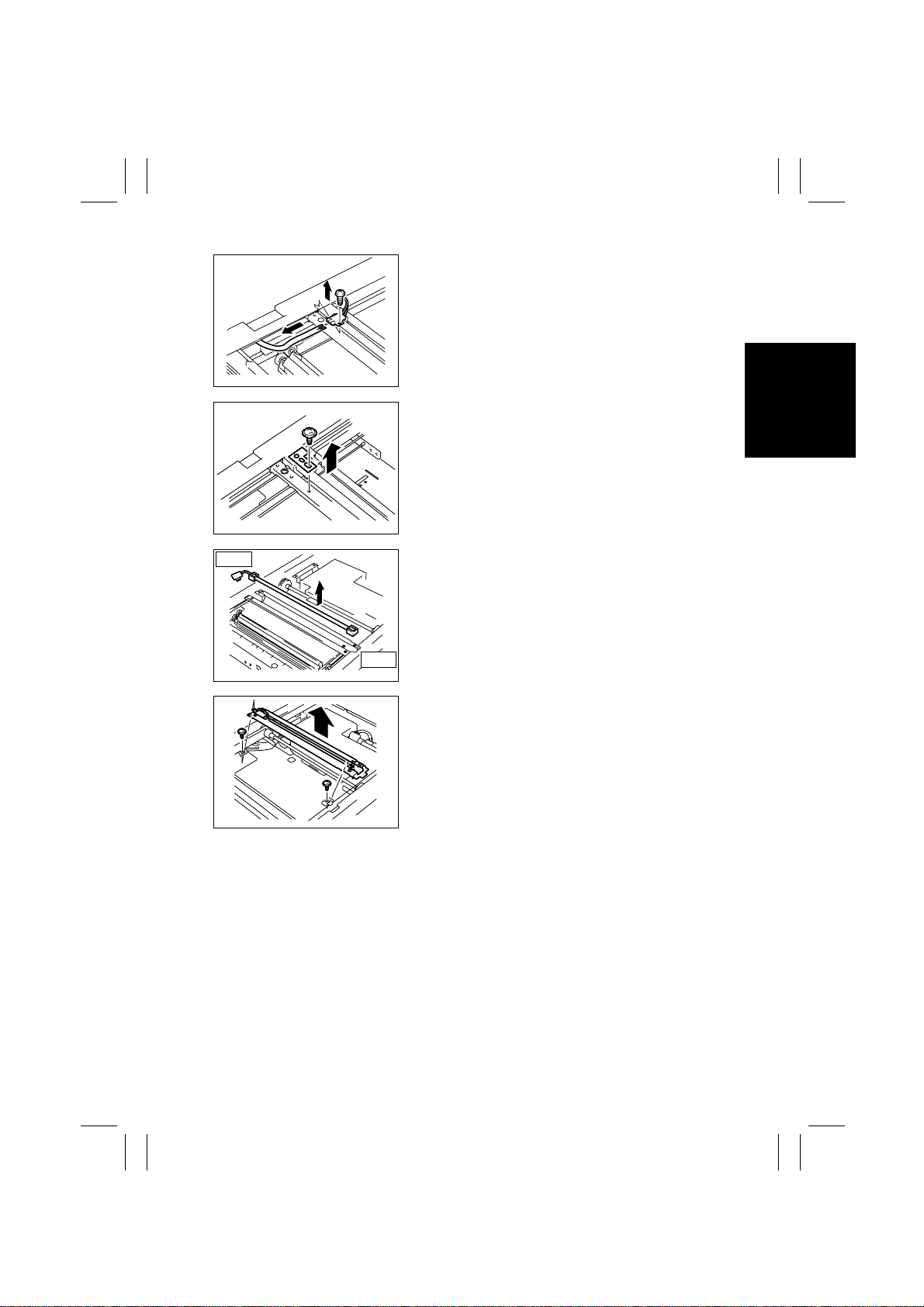
5. Remove one screw and the Original Size Detection
Sensor.
✽
Inch Areas Option.
1167D070AA
6. Snap off one E-ring and remove one mounting
screw from the front pulley and slide the pulley to
the rear.
1167D071AA
7. Snap off one E-ring and remove one mounting
screw from the rear pulley and slide the pulley to
the front.
1167D072AA
8. Remove the Scanner Drive Cable, hook end first.
D-18
Page 32

FrameMaker Ver.5.5E(PC) Di350 DIS/REASSEMBLY, ADJUSTMENT
98.12.09
(10) Winding of the Scanner Drive Cables
Pulley H
Pulley F
Pulley E
Pulley G
Pulley B
Pulley C
Pulley A
Front
1. Position the round bead of the Scanner Dr ive
Cable in the pulley as shown.
Pulley D
1167D047AB
Cable on Hook End
1167D051AC
1167D052AD
Cable on
Bead End
1167D053AD
2. Wind the hook end of the Scanner Drive Cable two
turns counterclockwise from the rear side to the
front.
3. Wind the bead end of the cable four turns clockwise from the front to the rear. Then, secure the
cable with tape.
NOTE
Make sure that no part of the cable rides on the other.
D-19
Page 33

FrameMaker Ver.5.5E(PC) Di350 DIS/REASSEMBLY, ADJUSTMENT
98.12.09
4. Slide the pulley to the front and install one mounting screw and one E-ring.
1167D073AA
5. Wind the bead end of the cable around pulley D
and pulley C, then hook the bead onto the Adjust-
Pulley D
able Anchor.
Pulley C
Pulley A
Pulley B
Cable Guide
1167D056AC
6. Wind the hook end of the cable around pulley A
and pulley B.
1167D057AC
7. Fit the hook end of the cable into the groove in the
Cable Guide and hook the spring.
1167D074AA
Rear
8. Position the round bead of the Scanner Dr ive
Cable in the pulley as shown.
1167D051AC
D-20
Page 34

FrameMaker Ver.5.5E(PC) Di350 DIS/REASSEMBLY, ADJUSTMENT
98.12.09
9. Wind the hook end of the cable two turns counterclockwise from the front to the rear.
Cable on Hook End
Pulley G
1167D054AD
Cable on
Bead End
1167D055AD
1167D075AA
Pulley H
1167D076AA
10. Wind the bead end of the cable four turns clockwise from the rear to the front. Then, secure the
cable with tape.
NOTE
Make sure that no part of the cable rides on the other.
11. Slide the pulley toward the rear and install one
mounting screw and one E-ring.
12. Wind the bead end of the cable around pulley H
and pulley G and hook the bead onto the Adjustable Anchor.
Pulley E
13. Wind the hook end of the cable around pulley E
and pulley F.
Pulley F
1167D078AA
D-21
Page 35

FrameMaker Ver.5.5E(PC) Di350 DIS/REASSEMBLY, ADJUSTMENT
98.12.09
14. Fit the hook end of the cable into the groove in the
Cable Guide and hook the spring.
Cable Guide
15. Peel off the tape from the pulleys at the front and rear.
16. Mount the Scanner.
17. Mount the Original Size Detection Sensor.
18. Reinstall the Left IR Cover.
19. Reinstall the Original Glass and ADF Glass Assy.
20. Perform the Focus-Positioning of the Scanner and 2nd/3rd Mirrors Carriage.
(For details, see ADJUSTMENT.)
1167D077AA
NOTE
Whenever the Scanner Drive Cables have been removed, be sure to make the following
adjustment: CD of Zoom Adjust (IR).
D-22
Page 36

FrameMaker Ver.5.5E(PC) Di350 DIS/REASSEMBLY, ADJUSTMENT
98.12.09
2-5. IMAGE TRANSFER SECTION
(1) Removal of the Image Transfer Roller
1. Open the Side Cover.
1167D006AD
2. Raise the Image Transfer Guide Plate.
1167D061AA
3. Remove the Image Transfer Roller and replace it.
NOTE
Do not touch the surface of the Image Transfer Roller
directly with bare hands.
4108D027AA
(2) Cleaning of the Comb Electrode
1. Open the Side Cover.
1171D021AA
D-23
Page 37

FrameMaker Ver.5.5E(PC) Di350 DIS/REASSEMBLY, ADJUSTMENT
98.12.09
2. Using a soft cloth dampened with alcohol, wipe the
Comb Electrode.
NOTES
•
Make sure the alcohol does not touch the surface of
the Image Transfer Roller.
•
When wiping the Comb Electrode, make sure the
1167D009AA
cloth is not caught by the ends of the combs.
(3) Cleaning of the Pre-Image Transfer Guide Plate
1. Open the Side Cover.
1171D021AA
2. Using a soft cloth dampened with alcohol, wipe the
NOTE
Make sure the alcohol does not touch the surface of
the Image Transfer Roller.
1167D010AA
(4) Replacement of the Ozone Filter
1. Remove the Rear Lower Cover.
2. Pull out the Ozone Filter and replace it.
1171D022AC
Pre-Image Transfer Guide Plate.
D-24
Page 38

FrameMaker Ver.5.5E(PC) Di350 DIS/REASSEMBLY, ADJUSTMENT
98.12.09
2-6. DEVELOPING SECTION
(1) Removal of the Imaging Cartridge
1. Open the Side Cover.
1171D021AA
2. Holding onto the green handles, slide the Imaging
Cartridge part of the way out.
3. Then grasp the handle on top of the cartridge and
pull the cartridge out.
NOTE
When installing the Imaging Cartridge, push it all the
1171D023AA
way into the machine.
If the cartridge is not properly installed, the PC Drum
protective shutter of the cartridge may not be opened
or may even be damaged.
D-25
Page 39

FrameMaker Ver.5.5E(PC) Di350 DIS/REASSEMBLY, ADJUSTMENT
98.12.09
2-7. FUSING SECTION
(1) Removal of the Fusing Unit
1. Open the Side Cover.
1171D021AA
2. Remove the Front Cover.
3. Unplug one connector at the front.
1167D020AB
4. Open the Exit Cover and unplug two connectors in
the rear.
5. Close the Exit Cover and remove two screws and
the Fusing Unit.
1167D021AB
(2) Removal of the Fusing Roller Heater Lamp, Fusing Right Roller, Fusing Left
Roller , Fusing Roller Thermistor, Fusing Roller Thermostat, and Fusing Roller
Heater Lamp Fuse
1. Open the Exit Cover.
2. Remove one screw and the Fusing Front Cover.
1171D036AA
D-26
Page 40

FrameMaker Ver.5.5E(PC) Di350 DIS/REASSEMBLY, ADJUSTMENT
98.12.09
3. Snap off one E-ring and remove the Exit Cover.
1171D037AA
4. Unhook one spring to free the Idle Lever.
5. Remove two harnesses.
6. Remove two screws and the Rear Cover.
1171D038AA
7. Remove three screws and the rear Lamp Holder.
1171D039AA
1171D041AA
1171D043AA
8. Remove one screw and the front Lamp Holder.
9. Remove one screw and the Fusing Roller Heater
Lamp.
10. Remove two screws and the Fusing Rear Guide
Assy.
11. Remove two pressure springs.
D-27
Page 41

FrameMaker Ver.5.5E(PC) Di350 DIS/REASSEMBLY, ADJUSTMENT
98.12.09
12. Snap off one E-ring and remove the front Misfeed
Clearing Lever Assy and bearing.
13. Remove the Fusing Right Roller.
1171D044AA
14. Snap off two retaining rings.
15. Remove one gear and two bushings.
16. Remove the Fusing Left Roller.
1171D045AA
NOTE
When the Fusing Left Roller is removed, it can cause
the spring to come off the Separator Finger. After the
Fusing Left Roller has later been reinstalled, be sure to
hook the spring onto the Separator Finger.
1171D046AA
1171D047AA
17. Remove one screw and the Fusing Roller Thermistor.
18. Remove two screws and the Fusing Roller Heater
Lamp Fuse.
19. Remove two screws and the Fusing Roller Thermostat.
D-28
Page 42

FrameMaker Ver.5.5E(PC) Di350 DIS/REASSEMBLY, ADJUSTMENT
98.12.09
3 ADJUSTMENT
3-1. ADJUSTMENT JIGS AND TOOLS USED
1. Scanner/Mirrors Carriage Positioning Jigs
1167D108AA
3-2. ADJUSTMENT REQUIREMENT LIST
Adjustment Item Requirements Adjustment Point Ref. Page
Touch Panel Adj. Automatically adjusted Control Panel D-32
Original Size Detecting Sensor
Adjustmen t
Loop Adjustment —
Edge Erase
Leading —
Trailing —
Right/Left —
Registration (CD) (Printer) 10 ± 2.0 mm
Registration (FD) (Printer)
Registration (IR)
CD
FD
Zoom Adjust (IR)
CD 200 ±1.0 mm
FD 300 ±1.5 mm
IR-Erasure Width —
↑↑
↑
↑
↑
↑
↑
↑↑
↑↑
↑↑
↑
↑
↑
D-33
D-34
D-35
D-36
D-37
D-38
D-40
D-42
D-44
D-46
D-48
D-50
D-29
Page 43

FrameMaker Ver.5.5E(PC) Di350 DIS/REASSEMBLY, ADJUSTMENT
98.12.09
3-3. ADJUSTMENT OF BELT TENSION
•
Adjustment of the Scanner Motor Timing Belt
1. Remove the Original Glass.
2. Remove four screws and the Cover.
1167D014AB
3. Loosen the two screws that secure the Scanner
Motor. Using a bar tension gage, pull the motor to
the right with a tension of 1000 g ±50 g and, at the
same time, tighten the mounting screws.
NOTE
After the adjustment, turn the timing belt to check that
1167D109AB
the belt teeth are in mesh with the pulley grooves.
D-30
Page 44

FrameMaker Ver.5.5E(PC) Di350 DIS/REASSEMBLY, ADJUSTMENT
98.12.09
3-4. TEST PRINT
NOTES
This function is used to make the following electrical and image adjustments:
•
Registration (CD) (Printer)
•
Registration (FD) (Printer)
•
Registration (IR)
•
Zoom Adjust (IR)
Adjustment Procedure
1. Check that “Copy Track Mode” of “Copy Track”
under “Admin. Management” available from “Utili ty”
is “OFF.”
1171D026CA
2. Select the paper source for the test print.
1171D027CA
3. Press the Utility key on the control panel and touch
[User Management].
1171D028CA
1171D029CA
4. Touch [Test Print] to produce a test pattern.
D-31
Page 45

FrameMaker Ver.5.5E(PC) Di350 DIS/REASSEMBLY, ADJUSTMENT
98.12.09
3-5. ELECTRICAL/IMAGE ADJUSTMENT
(1) T ouch P anel Adj.
NOTE
Make this adjustment after either of the following procedures have been perform ed:
•
Memory Clear
•
Control Panel replacement
Adjustment Procedure
1. Call the Initial mode to the screen. (For details, see SWITCHES ON PWBs, TECH.
REP. SETTINGS.)
2. Touch [Touch Panel Adj.].
12
1171D056CA
4
“Initial” Screen
3. Touch + on screen 1.
NOTE
At this time, ensure that the very center of “+
similar device.
4. Touch + on screen 2.
5. Touch + on screen 3.
6. Touch + on screen 4.
D-32
1171D057CA
3
1171D058CA1171D059CA
is touched using the tip of a ballpoint pen or
”
Page 46

FrameMaker Ver.5.5E(PC) Di350 DIS/REASSEMBLY, ADJUSTMENT
98.12.09
(2) Original Size Detecting Sensor Adjustment (F7-1)
NOTE
Make this adjustment after any of the following procedures have been perfor med:
•
Memory Clear
•
A faulty original size detection occurs
•
Replacement of the CCD Unit and Scanner parts (including the Exposure Lamp)
•
RAM Board replacement
Adjustment Procedure
1167D110AB
2. Call the Tech. Rep. mode to the screen.
3. Touch [Function] to call the Function menu.
4. Touch F7-1 Original Size Detecting Sensor Adjustment.
5. Press the Start key to run the Original Size Detecting Sensor Adjustment function.
1. Stack five sheets of blank A3 or 11” × 17” paper on
the Original Glass and lower the Original Cover.
NOTE
The Start key remains lit up orange while this function is being run and lights up green as
soon as the sequence is completed.
D-33
Page 47

FrameMaker Ver.5.5E(PC) Di350 DIS/REASSEMBLY, ADJUSTMENT
98.12.09
(3) Loop Adjustment
Requirement
Adjust so that a correct loop is formed before the Synchronizing Rollers when paper is fed
through.
Adjust Mode Setting Value
Loop Adjustment -5 to +5
NOTE
This adjustment is to be made when any of the following symptoms occurs: variations in the
amount of print leading edge void, paper skew, and misfeed.
Adjustment Procedure
1. Call the Tech. Rep. mode to the screen.
2. Touch [Tech. Rep. Choice], then [Printer].
3. Touch [Loop Adjustment] to enter the Loop Adjustment mode.
4. Select the paper source for which the adjustment is to be made.
5. Press the Clear key to clear the current setting.
6. Enter the new setting value from the 10-Key Pad.
Setting Instructions
Change the setting value as necessary until there are no variations in the amount of void
image along the leading edge, skewed feeding, dog-ear, or misfeed.
Use to change the + or - sign.
1171D030CA
Setting Value
Use to change the + or - sign.
Use to clear setting value.
Use to enter setting value.
1171D061CA
7. Touch the [END] key to validate the setting value.
Caution
Be sure to touch the END key before returning to normal operation mode. If the Panel
Reset Key is used, the previous setting remains valid.
8. Perfor m the same step s to adjust for the other paper sources.
D-34
Page 48

FrameMaker Ver.5.5E(PC) Di350 DIS/REASSEMBLY, ADJUSTMENT
98.12.09
(4) Edge Erase
1. Leading
Requirement
A
Adjust so that the erase width on the leading edge falls
within the range of 0 to 5 mm.
Adjust Mode Setting Range
Edge Erase/Leading 0 to 5
1171D003AA
NOTE
This adjustment must be made when the PH Unit has been replaced and after Registration
(CD/FD) (Printer) has been made.
Adjustment Procedure
1. Call the Tech. Rep. mode to the screen.
2. Touch [Tech. Rep. Choice], then [Printer].
3. Touch [Edge Erase] and then [Leading] to enter the Leading Edge Erase adjustment
mode.
4. Press the Clear key to clear the current setting.
5. Enter the new setting value from the 10-Key Pad.
Setting Instructions
To make the edge erase width smaller, decrease the setting value.
To make the edge erase width greater, increase the setting value.
Use to clear setting value.
Setting Value
1171D031CA
Use to enter setting value.
1167D069AA
6. Touch the [END] key to validate the setting value.
Caution
Be sure to touch the END key before returning to normal operation mode. If the Panel
Reset Key is used, the previous setting remains valid.
D-35
Page 49

FrameMaker Ver.5.5E(PC) Di350 DIS/REASSEMBLY, ADJUSTMENT
98.12.09
2. Trailing
Requirement
Adjust so that the erase width on the trailing edge falls
A
within the range of 0 to 5 mm.
Adjust Mode Setting Range
Edge Erase/Trailing 0 to 5
1171D004AA
NOTE
This adjustment must be made when the PH Unit has been replaced and after Registration
(CD/FD) (Printer) has been made.
Adjustment Procedure
1. Call the Tech. Rep. mode to the screen.
2. Touch [Tech. Rep. Choice], then [Printer].
3. Touch [Edge Erase] and then [Trailing] to enter the Trailing Edge Erase adjustment
mode.
4. Press the Clear key to clear the current setting.
5. Enter the new setting value from the 10-Key Pad.
Setting Instructions
To make the edge erase width smaller, decrease the setting value.
To make the edge erase width greater, increase the setting value.
Use to clear setting value.
1171D031CA
Setting Value
Use to enter setting value.
1167D069AA
6. Touch the [END] key to validate the setting value.
Caution
Be sure to touch the END key before returning to normal operation mode. If the Panel
Reset Key is used, the previous setting remains valid.
D-36
Page 50

FrameMaker Ver.5.5E(PC) Di350 DIS/REASSEMBLY, ADJUSTMENT
98.12.09
3. Right/Left
Requirement
Adjust so that the erase width on the right/left edge
falls within the range of 0 to 5 mm.
A
Adjust Mode Setting Range
Edge Erase/Right/Left 0 to 5
A
1171D005AA
NOTE
This adjustment must be made when the PH Unit has been replaced and after Registration
(CD) (Printer) have been made.
Adjustment Procedure
1. Call the Tech. Rep. mode to the screen.
2. Touch [Tech. Rep. Choice], then [Printer].
3. Touch [Edge Erase] and then [Right/Left] to enter the Right/Left Edge Erase adjustment
mode.
4. Press the Clear key to clear the current setting.
5. Enter the new setting value from the 10-Key Pad.
Setting Instructions
To make the edge erase width smaller, decrease the setting value.
To make the edge erase width greater, increase the setting value.
Use to clear setting value.
1171D031CA
Setting Value
Use to enter setting value.
1167D069AA
6. Touch the [END] key to validate the setting value.
Caution
Be sure to touch the END key before returning to normal operation mode. If the Panel
Reset Key is used, the previous setting remains valid.
D-37
Page 51

FrameMaker Ver.5.5E(PC) Di350 DIS/REASSEMBLY, ADJUSTMENT
98.12.09
(5) Registration (CD) (Printer)
Requirement
A
1171D006AA
Specification Adjust Mode Setting Range
1-Sided: 10 ±2.0 mm
2-Sided: 10 ±3.0 mm
NOTE
This adjustment must be made when the PH Unit has been replaced and, for 2-sided, af ter
Registration (CD) (Printer) for each paper source for 1-sided and Registration (FD) (Printer)
have been made.
Adjustment Procedure
1. Produce a test pattern. (For details, see 3-4. TEST PRINT.)
2. 1-Sided: Check to see if width A on the test pattern meets the specifications.
2-Sided: Using the test pattern output as the original, make an ordinary 2-sided copy .
Check to see if width A on the second side of the 2-sided copy meets the
specifications.
If width A falls outside the specified range, perform these steps to make the adjustment.
Adjust so that width A on the test pattern output falls
within the following range.
Registration (CD) -4.0 to +4.0
D-38
Page 52

FrameMaker Ver.5.5E(PC) Di350 DIS/REASSEMBLY, ADJUSTMENT
98.12.09
3. Call the Adjust mode to the screen.
4. Touch [Printer] and [Registration (CD)], in that order.
5. Select the paper source for which the adjustment is to be made.
6. Press the Clear key to clear the current setting.
7. Enter the new setting value from the 10-Key Pad.
Setting Instructions
If width A is wider than specifications, make the setting value smaller than the current one.
If width A is narrower than specifications, make the setting value greater than the current
one.
✽
If a single adjustment procedure does not successfully bring width A into the specified
range, try another setting value.
Use to change the + or - sign.
1171D032CA
Setting Value
Use to change the + or - sign.
Use to clear setting value.
Use to enter setting value.
1171D061CA
8. Touch the [END] key to validate the setting value.
Caution
Be sure to touch the END key before returning to normal operation mode. If the Panel
Reset Key is used, the previous setting remains valid.
9. Perfor m the same step s to adjust for the other paper sources.
D-39
Page 53

FrameMaker Ver.5.5E(PC) Di350 DIS/REASSEMBLY, ADJUSTMENT
98.12.09
(6) Registration (FD) (Printer)
Requirement
Adjust so that width A on the test pattern output falls
within the following range.
A
1171D007AA
Specification Adjust Mode Setting Range
10 ±2.0 mm Registration (FD) -19 to +19
NOTE
This adjustment must be made when the PH Unit has been replaced and after Registration
(CD) (Printer) has been made.
Adjustment Procedure
1. Produce a test pattern. (For details, see 3-4. TEST PRINT.)
2. Check to see if width A on the test pattern meets the specifications.
If width A falls outside the specified range, perform these steps to make the adjustment.
D-40
Page 54

FrameMaker Ver.5.5E(PC) Di350 DIS/REASSEMBLY, ADJUSTMENT
98.12.09
3. Call the Adjust mode to the screen.
4. Touch [Printer] and [Registration (FD)], in that order.
5. Select the paper source for which the adjustment is to be made.
6. Press the Clear key to clear the current setting.
7. Enter the new setting value from the 10-Key Pad.
Setting Instructions
If width A is wider than specifications, make the setting value smaller than the current one.
If width A is narrower than specifications, make the setting value greater than the current
one.
✽
If a single adjustment procedure does not successfully bring width A into the specified
range, try another setting value.
Use to change the + or - sign.
Setting Value
1171D033CA
Use to change the + or - sign.
Use to clear setting value.
Use to enter setting value.
1171D061CA
8. Touch the [END] key to validate the setting value.
Caution
Be sure to touch the END key before returning to normal operation mode. If the Panel
Reset Key is used, the previous setting remains valid.
D-41
Page 55

FrameMaker Ver.5.5E(PC) Di350 DIS/REASSEMBLY, ADJUSTMENT
98.12.09
(7) Registration (IR)
1. CD
Requirement
A
1171D009AA
Specification Adjust Mode Setting Range
10 ±2.0 mm Registration (CD) -127 to +127
NOTE
This adjustment must be made when the PH Unit has been replaced and after the adjustments of Registration (CD and FD) (Printer) and CD of Zoom Adjust (IR) have been made.
Adjustment Procedure
1. After the adjustments of Registration (CD and FD) (Printer) and CD of Zoom Adjust (IR)
have been completed, produce a test pattern. (For details, see 3-4. TEST PRINT.)
2. Place the test pattern output on the Original Glass and make a copy of it.
3. Check to see if width A on the test pattern copy meets the specifications.
If width A falls outside the specified range, perform these steps to make the adjustment.
Place the test pattern output after the adjustments of
Registration (CD and FD) (Printer) have been completed on the Original Glass and make a copy of it.
Adjust so that width A on the test pattern copy falls
within the following range.
D-42
Page 56

FrameMaker Ver.5.5E(PC) Di350 DIS/REASSEMBLY, ADJUSTMENT
98.12.09
4. Call the Adjust mode to the screen.
5. Touch [IR], [Registration], and [CD], in that order.
6. Press the Clear key to clear the current setting.
7. Enter the new setting value from the 10-Key Pad.
Setting Instructions
If width A is wider than specifications, make the setting value smaller than the current one.
If width A is narrower than specifications, make the setting value greater than the current
one.
✽
If a single adjustment procedure does not successfully bring width A into the specified
range, try another setting value.
Use to change the + or - sign.
Setting Value
1171D034CA
Use to change the + or - sign.
Use to clear setting value.
Use to enter setting value.
1171D061CA
8. Touch the [END] key to validate the setting value.
Caution
Be sure to touch the END key before returning to normal operation mode. If the Panel
Reset Key is used, the previous setting remains valid.
D-43
Page 57

FrameMaker Ver.5.5E(PC) Di350 DIS/REASSEMBLY, ADJUSTMENT
98.12.09
2. FD
Requirement
1171D007AA
Specification Adjust Mode Setting Range
10 ±2.0 mm Registration (FD) -127 to +127
NOTE
This adjustment must be made when the PH Unit has been replaced and after the adjustments of Registration (CD and FD) (Printer) and FD of Zoom Adjust (IR) have been made.
Adjustment Procedure
1. After the adjustments of Registration (CD and FD) (Printer) and FD of Zoom Adjust (IR)
have been completed, produce a test pattern. (For details, see 3-4. TEST PRINT.)
2. Place the test pattern output on the Original Glass and make a copy of it.
3. Check to see if width A on the test pattern copy meets the specifications.
If width A falls outside the specified range, perform these steps to make the adjustment.
Place the test pattern output after the adjustments of
Registration (CD and FD) (Printer) have been completed on the Original Glass and make a copy of it.
A
Adjust so that width A on the test pattern copy falls
within the following range.
D-44
Page 58

FrameMaker Ver.5.5E(PC) Di350 DIS/REASSEMBLY, ADJUSTMENT
98.12.09
4. Call the Adjust mode to the screen.
5. Touch [IR], [Registration], and [FD], in that order.
6. Press the Clear key to clear the current setting.
7. Enter the new setting value from the 10-Key Pad.
Setting Instructions
If width A is wider than specifications, make the setting value smaller than the current one.
If width A is narrower than specifications, make the setting value greater than the current
one.
✽
If a single adjustment procedure does not successfully bring width A into the specified
range, try another setting value.
Use to change the + or - sign.
1171D034CA
Setting Value
Use to change the + or - sign.
Use to clear setting value.
Use to enter setting value.
1171D061CA
8. Touch the [END] key to validate the setting value.
Caution
Be sure to touch the END key before returning to normal operation mode. If the Panel
Reset Key is used, the previous setting remains valid.
D-45
Page 59

FrameMaker Ver.5.5E(PC) Di350 DIS/REASSEMBLY, ADJUSTMENT
98.12.09
(8) Zoom Adjust (IR)
1. CD
Requirement
1. The difference should be within ±1.0% of the actual length.
2. Adjust so that the following specifications are satisfied with a scale length of 300 mm.
Zoom Ratio Specification Adjust Mode Setting Range
Full size (×1.000) 300 ±3.0 mm Zoom Adjust (CD) 0.990 to 1.010
NOTE
This adjustment must be made when the Scanner Drive Cables have been replaced and
after the adjustments of Registration (CD and FD) (Printer) have been made.
Adjustment Procedure
1167D111AA
1138D154AA
1. Place a scale in parallel with the Original Width
Scale and make a copy. (Note that the scale is perpendicular to the Original Length Scale.)
✽
Use the full size (×1.000) mode and A3 or 11” × 17”
paper.
✽
If the scale is of plastic and transparent, place a
blank sheet of paper over it.
2. Measure the length of the scale on the copy to find
the difference.
✽
If the difference is outside the specification, adjust
by following the procedure shown below.
D-46
Page 60

FrameMaker Ver.5.5E(PC) Di350 DIS/REASSEMBLY, ADJUSTMENT
98.12.09
3. Call the Adjust mode to the screen.
4. Touch [IR], [Zoom Adjust], and [CD], in that order.
5. Press the Clear key to clear the current setting.
6. Enter the new setting value from the 10-Key Pad.
Setting Instructions
If the scale on the copy is longer than the actual scale, decrease the setting value.
If the scale on the copy is shorter than the actual scale, increase the setting value.
✽
If the measurement does not fall within the specifications through one setting, try another
setting.
Use to clear setting value.
1171D035CA
Setting Value
Use to enter setting value.
1167D069AA
7. Touch the [END] key to validate the setting value.
Caution
Be sure to touch the END key before returning to normal operation mode. If the Panel
Reset Key is used, the previous setting remains valid.
D-47
Page 61

FrameMaker Ver.5.5E(PC) Di350 DIS/REASSEMBLY, ADJUSTMENT
98.12.09
2. FD
Requirement
1. The difference should be within ±1.0% of the actual length.
2. Adjust so that the following specifications are satisfied with a scale length of 200 mm.
Zoom Ratio Specification Adjust Mode Setting Range
Full size (×1.000) 200 ±2.0 mm Zoom Adjust (FD) 0.990 to 1.010
NOTE
This adjustment must be made when the CCD Unit has been replaced and after the adjustments of Registration (CD and FD) (Printer) have been made.
Adjustment Procedure
1167D112AA
1134D124AA
1. Place a scale in parallel with the Original Length
Scale and make a copy.
✽
Use the full size (X1.000) mode and paper with a
width of 200 mm or more.
✽
If the scale is of plastic and transparent, place a
blank sheet of paper over it.
2. Measure the length of the scale on the copy to find
the difference.
✽
If the difference is outside the specification, adjust
by following the procedure shown below.
D-48
Page 62

FrameMaker Ver.5.5E(PC) Di350 DIS/REASSEMBLY, ADJUSTMENT
98.12.09
3. Call the Adjust mode to the screen.
4. Touch [IR], [Zoom Adjust], and [FD], in that order.
5. Press the Clear key to clear the current setting.
6. Enter the new setting value from the 10-Key Pad.
Setting Instructions
If the scale on the copy is longer than the actual scale, decrease the setting value.
If the scale on the copy is shorter than the actual scale, increase the setting value.
✽
If the measurement does not fall within the specifications through one setting, try another
setting.
Use to clear setting value.
1171D035CA
Setting Value
Use to enter setting value.
1167D069AA
7. Touch the [END] key to validate the setting value.
Caution
Be sure to touch the END key before returning to normal operating mode. If the Panel
Reset Key is used, the previous setting remains valid.
D-49
Page 63

FrameMaker Ver.5.5E(PC) Di350 DIS/REASSEMBLY, ADJUSTMENT
98.12.09
(9) IR-Erasure Width
Requirement
A
Set so that the erase width along four edges of the
paper falls within the range of 0 to 3 mm.
A
Adjust Mode Setting Range
IR-Erasure Width 0 to 3
A
A
1171D062AA
NOTE
This adjustment must be made when a shadow is produced from the Original Scale.
Adjustment Procedure
1. Call the Tech. Rep. mode to the screen.
2. Touch [Tech. Rep. Choice].
3. Touch [IR-Erasure Width] to enter the IR-Erasure Width mode.
4. Press the Clear key to clear the current setting.
5. Enter the new setting value from the 10-Key Pad.
Setting Instructions
To make the erase width along four edges of the paper smaller, decrease the setting value.
To make the erase width along four edges of the paper greater, increase the setting value.
Use to clear setting value.
Setting Value
1171D064CA
Use to enter setting value.
1167D069AA
6. Touch the [END] key to validate the setting value.
Caution
Be sure to touch the END key before returning to normal operation mode. If the Panel
Reset Key is used, the previous setting remains valid.
D-50
Page 64

FrameMaker Ver.5.5E(PC) Di350 DIS/REASSEMBLY, ADJUSTMENT
98.12.09
3-6. OTHER ADJUSTMENTS
•
Focus-Positioning of the Scanner and 2nd/3rd Mirrors Carriage
NOTE
Make this adjustment after any of the following procedures has been performed:
•
After the Scanner Drive Cable has been replaced.
•
When the Scanner Fixing Bracket has been removed from the Scanner Drive Cable.
•
When the Scanner Drive Cable comes unwound.
Requirement
With the Scanner fixed to the Scanner Drive Cables, there should be no gap between the
Scanner/Mirrors Carriage Positioning Jig and the Scanner and also between the Scanner/
Mirrors Carriage Positioning Jig and the 2nd/3rd Mirrors Carriage.
Adjustment Procedure
1167D113AA
1167D114AA
Scanner/Mirrors Carriage Positioning Jig
2nd/3rd
Mirrors
Carriage
Scanner
1167D115AC
1. Remove the Exposure Lamp. (For details, see
steps 1 through 7, (8) Removal of the Scanner, 2-4
OPTICAL SECTION.)
2. Temporarily loosen the set screws of the cable
holding plate of the Scanner Drive Cable.
3. Fit the Scanner/Mirrors Carriage Positioning Jigs in
the space between the Scanner and 2nd/3rd Mirrors Carriage.
4. Press the Scanner up against the jig and 2nd/3rd
Mirrors Carriage and, at the same time, tighten the
set screws of the cable holding plate.
D-51
Page 65

FrameMaker Ver.5.5E(PC) Di350 DIS/REASSEMBLY, ADJUSTMENT
98.12.09
Adjusting Screw
NOTE
If the Scanner does not run parallel with the 2nd/3rd
Mirrors Carriage when the Scanner/Mirrors Carriage
Positioning Jigs are in position, turn the adjusting
screw for the rear Scanner Drive Cable as necessary.
1167D116AB
✽
If the Scanner/Mirrors Carriage Positioning Jigs are not available, follow these steps to
make the adjustment.
1. Temporarily loosen the set screws of the cable
holding plate of the Scanner Drive Cable.
1167D113AA
2. Obtain a distance of 13 mm between the 2nd/3rd
Mirrors Carriage and rail.
13 mm
1167D117AC
Adjusting Screw
3. Secure the Scanner where it is located at a position 21 mm from the right side face.
4. Tighten the set screws of the cable holding plate.
21 mm
1167D118AC
NOTE
If the Scanner does not run parallel with the 2nd/3rd
Mirrors Carriage, turn the adjusting screw for the rear
Scanner Drive Cable as necessary.
1167D116AB
D-52
Page 66

FrameMaker Ver.5.5E(PC) Di350 DIS/REASSEMBLY, ADJUSTMENT
98.12.09
4 MISCELLANEOUS
4-1. INSTALLATION OF THE KEY COUNTER SOCKET (OPTION)
1. Remove the Front Cover.
2. Remove the knockout from the Front Upper Cover.
3. Using two screws, secure the Counter Mounting
Bracket.
1167D022AB
4. Route the harness of the Key Counter as shown.
1167D025AB
1167D023AB
1167D024AB
5. Connect the Key Counter Socket connector.
6. Using one screw and one screw and nut, secure
the counter socket.
7. Using two screws, secure the Key Counter Cover.
NOTE
When the Key Counter Socket is mounted, set to “ON
the “Key Counter” available from the Security mode.
”
D-53
Page 67

FrameMaker Ver.5.5E(PC) Di350 DIS/REASSEMBLY, ADJUSTMENT
98.12.09
4-2. REMOUNTING THE EEPROM (IC3A)
NOTES
•
If the Imaging Cartridge is not to be replaced after the Master Board has been replaced
with a new one, be sure to remount the EEPROM (IC3A) from the old to new Master
Board.
•
If the Master Board has been replaced with a new one and the EEPROM (IC3A) has not
been remounted, be sure to replace the Imaging Cartridge with a new one. Because the
EEPROM contains no data in this case, make settings and readjustments as necessar y.
1. Remove the Master Board. (For details, see 2-2. REMOVAL OF CIRCUIT BOARDS
AND OTHER ELECTRICAL COMPONENTS.)
2. Demount the EEPROM (IC3A) from the new Master Board.
3. Demount the EEPROM (IC3A) from the old Master Board and remount it onto the new
Master Board.
New Master Board
New EEPROM
A
A
1171D049AA
Old EEPROM
Old Master Board
1171D048AA
NOTE
Note the alignment notch on the EEPROM (IC3A)
when mounting the IC.
D-54
Page 68

FrameMaker Ver.5.5(PC) Di350 SWITCHES ON PWBs/TECH. REP. SETTINGS
98.11.25
Di350
SWITCHES ON PWBs,
TECH. REP. SETTINGS
17196
Page 69

Page 70

FrameMaker Ver.5.5E(PC) Di350 SWITCHES ON PWBs/TECH. REP. SETTINGS
98.11.25
CONTENTS
1. PRECAUTIONS FOR HANDLING THE PWBs ................................................S-1
1-1. Precautions for Transportation and Storage .................... ........................S-1
1-2. Precautions for Replacement and Inspection ..........................................S-1
2. CONTROL PANEL KEYS AND TOUCH PANEL ............................................. S-2
2-1. Control Panel Keys ..................................................................................S-2
2-2. Explanation of the Touch Panel .............................................................. .S-3
(1) Basic Screen ...................................................................................S-3
(2) Warning Screens ........................ ....................... ..............................S-4
3. FUNCTION OF SWITCHES AND OTHER PARTS ON PWBs ........................S-5
3-1. PWB Location ..........................................................................................S-5
3-2. PWB-A (Master Board) ............................................................................S-5
3-3. UN1 (Control Panel) .................... .......................... ..................................S-6
3-4. PWB-L (PPM Switching Board) .............. ......................... ........................S-6
3-5. UN2 (MFB Board) ....................................................................................S-7
4. USER’S CHOICE MODE .................................................................................S-9
4-1. User’s Choice Selection Screen ..............................................................S-9
4-2. User’s Choice Function Setting Procedure ..............................................S-9
4-3. User’s Choice Function Tree ................................................................... S-10
4-4. Settings in the User’s Choice Mode .................................................. .......S-11
5. TECH. REP. MODE .........................................................................................S-16
5-1. Tech. Rep. Mode Menu Screen ...............................................................S-16
5-2. Tech. Rep. Mode Function Setting Procedure .........................................S-16
5-3. Tech. Rep. Mode Setting Tree .................................................................S-17
5-4. Settings in the Tech. Rep. Mode .............................................................S-18
(1) Tech. Rep. Choice ...........................................................................S-18
(2) System Input ....................................................................................S-22
(3) Administrator # Input .......................................................................S-23
(4) Counter ............................................................................................ S-23
(5) Function ........................................................................................... S-28
(6) I/O Check .........................................................................................S-29
(7) Movement Check .................................................................... .........S-30
(8) RD Mode (SMART) ......................................... ................................S-31
(9) ROM Version ...................................................................................S-33
(10) Level History ................ ................................................................. ...S-34
6. SECURITY MODE ...........................................................................................S-35
6-1. Security Mode Menu Screen ...................................................................S-35
6-2. Security Mode Function Setting Procedure .............................................S-35
6-3. Settings in the Security Mode ..................................................................S-36
7. ADJUST MODE ............................................................. ..................................S-39
7-1. Adjust Mode Menu Screen ............................................................... .... .. .S-39
7-2. Adjust Mode Function Setting Procedure ......... .......................... .............S-39
7-3. Adjust Mode Function Tree ......................................................................S-40
7-4. Settings in the Adjust Mode .......................... ......................... ..................S-40
(1) Printer .............................................................................................. S-40
(2) IR ..................................................................................................... S-41
8. INITIAL MODE .................................................................................................S-42
i
Page 71

FrameMaker Ver.5.5E(PC) Di350 SWITCHES ON PWBs/TECH. REP. SETTINGS
98.11.25
8-1. Initial Mode Menu Screen ........................................................................S-42
8-2. Initial Mode Function Setting Procedure ..................................................S-42
8-3. Settings in the Initial Mode ............................................. ..........................S-43
ii
Page 72

FrameMaker Ver.5.5(PC) Di350 SWITCHES ON PWBs/TECH. REP. SE TTINGS
98.11.25
1 PRECAUTIONS FOR HANDLING THE PWBs
1-1. Precautions for Transportation and Storage
•
Before transporting or storing the PWBs, put them in protective conductive cases or bags
so that they are not subjected to high temperature and are not exposed to direct sunlight.
•
Protect the PWBs from any external force so that they are not bent or damaged.
•
Once the PWB has been removed from its conductive case or bag, never place it directly
on an object that is easily charged with static electricity (such as a carpet or plastic bag).
•
Do not touch the parts and printed patterns on the PWBs with bare hands.
1-2.
•
•
•
•
Precautions for Replacement and Inspection
Whenever replacing the PWB, make sure that the power cord of the copier has been
unplugged.
When the power is on, the connectors should never be plugged in or unplugged.
Use care not to strap the pins of an IC with a metal tool.
When touching the PWB, wear a wrist strap and connect its cord to a securely grounded
place whenever possible. If you cannot wear a wrist strap, touch the metal part to discharge static electricity before touching the PWB.
S-1
Page 73

FrameMaker Ver.5.5(PC) Di350 SWITCHES ON PWBs/TECH. REP. SE TTINGS
98.11.25
2 CONTROL PANEL KEYS AND TOUCH PANEL
✽
For more details, see the Operator’s Manual shipped with the copier.
2-1.
Control Panel Keys
1. Touch Panel
•
Shows various screens and messages.
2. Utility Key
•
Press to show the User Mode menu.
3. Mode Check Key
•
Shows the Mode Check screen on which
the user can check the current copying
settings.
4. Access Mode Key
•
Used to enter the access number. After
the access number has been entered,
pressing this key will allow the user to
make copies.
5. Interrupt Key
•
Sets the copier into, or lets it leave, the
Interrupt mo de.
6. Display Contrast Knob
•
Turn to vary the brightness of the Touch
Panel.
321
4
5
6
7891011
7. Panel Reset Key
•
Clears all settings made on the control
panel, setting the copier back into the initial mode.
•
Cancels currently reserved jobs.
✽
It does not clear the zoom ratios and job
settings stored in memory and Interrupt
mode.
8. Clear Key
•
Clears the number-of-copies setting,
zoom ratio, and counter count.
•
Cancels the image data read.
9. Stop Key
•
Press to stop a scanning cycle.
•
Press to stop a print cycle.
10. Start Key
•
Press to start the document scanning
sequence.
•
Press to start a print cycle.
11. 10-key Pad
•
Numeric key pad used for entering the
number of copies to be made, zoom ratio,
access number, and the Tech. Rep. mode
settings.
1166O238EB
S-2
Page 74

FrameMaker Ver.5.5(PC) Di350 SWITCHES ON PWBs/TECH. REP. SE TTINGS
98.11.25
2-2. Explanation of the Touch Panel
(1) Basic Screen
•
The Basic screen is the initial screen that appears when the copier panel is reset or auto
reset is activated.
1
2
3
4
5
1. Supplementary Function Key
•
Selects the corresponding menu screen,
either Auxiliary, Density, Orig.
Basics.
2. Message Display
•
Shows the current copier status, operating instructions, caution/warning messages, and other data including the
number of copies selected.
3. Basic Function Keys
•
Allows the user to select the finishing,
zoom ratio, and copy paper.
Copy, or
1168P169CC
4. Function Display
•
Shows graphic representations of the settings currently made for Orig.
and Finishing.
5. Status Display
•
Shows what is being done with the current
job and other data.
Copy
S-3
Page 75

FrameMaker Ver.5.5(PC) Di350 SWITCHES ON PWBs/TECH. REP. SE TTINGS
98.11.25
(2) Warning Screens
•
The warning screen may be a malfunction display, error display, warning display, or a
caution display.
<Malfunction Display>
•
A malfunction display is given when trouble occurs which cannot be corrected by
the user.
Example: Malfunctions that can be identi-
fied with a specific code.
<Warning Display>
•
A warning display is given when any further copier operation will not be possible,
or only a defective cop y will be produced,
because of erroneous or illegal panel settings or other cause.
Example: Unmatched paper size in Auto
Paper.
<Error Display>
•
An error display is given when trouble
occurs which can be corrected by the
user.
Example: P aper misfeed, t oner empty , door
open.
1168P167CD1171S001CB
<Caution Display>
•
A caution display is given when, though
further copier operation will be possible, it
could result in a malfunction.
Example: Install new Imaging Cartridge.
S-4
1171S003CB1171S002CC
Page 76

FrameMaker Ver.5.5(PC) Di350 SWITCHES ON PWBs/TECH. REP. SE TTINGS
98.11.25
3
FUNCTION OF SWITCHES AND OTHER PARTS ON PWBs
3-1. PWB Location
PWB-L
UN2
PWB-A
3-2. PWB-A (Master Board)
UN1
1171S004AA
S1
1167S002AA
1167S002AA
Symbol Name Description
S1 Test Print Switch Used to run a test print cycle.
S-5
Page 77

FrameMaker Ver.5.5(PC) Di350 SWITCHES ON PWBs/TECH. REP. SE TTINGS
98.11.25
3-3. UN1 (Control Panel)
SW37
1167S018AA
1167S018AA
Symbol Name Description
SW37 Warm Restart Switch
•
Used to enter the initial mode.
•
Used to restart the copier after a breakdown.
3-4. PWB-L (PPM Switching Board)
SW1
H L
SW1
Symbol Name Description
S1 Low-Speed Mode
Selecting Switch
Used to make longer the paper-to-paper intervals as
a means of preventing the problem in which sheets of
paper are fed out untidily when large size paper left to
stand under high humidity condition is being used.
✽
Keep this switch in the H position, as it is only for
special users.
1167S026AB
1167S026AB
S-6
Page 78

FrameMaker Ver.5.5(PC) Di350 SWITCHES ON PWBs/TECH. REP. SE TTINGS
98.11.25
3-5. UN2 (MFB Board)
U6
U6
1167S027AA
Symbol Name Description
U6 Forced Memory Clear Used when it is not possible to clear RAM by warm
✽
Be careful about using these pins, as closing these pins clears all data including counter
data.
<Clearing Procedure>
1. Turn OFF the Power Switch.
2. Remove the Upper Cover and MFB Box Cover.
3. Close U6 and, in that condition, turn ON the Power Switch.
NOTE
Use care not to close any other circuit.
4. When the initial screen appears, turn the Power Switch OFF.
5. Open U6.
NOTE
When Forced RAM Clear has been performed, make these adjustments and settings once
again in this order:
1. “Marketing Area” of “Initial mode”
2. “Memory Clear” of “Initial mode”
3. Other adjustments and settings as necessary
restart.
S-7
Page 79

FrameMaker Ver.5.5(PC) Di350 SWITCHES ON PWBs/TECH. REP. SE TTINGS
98.11.25
<Data/Conditions Cleared by Reset Switches/Pins>
Switches/Pins
Data/Conditions Cleared
Misfeed display
Malfunction display
(other than Fusing)
Malfunction display
(all including Fusing)
Erratic operation/
display
User’s Choice — —
Tech. Rep. Mode — —
Counter — — —
RD Mode — — —
Security Mode — —
Adjust Mode —————
❍
: Cleared (initialized) —: Not cleared
Power
Switch
OFF/ON
❍❍❍
❍❍❍
——
——
Side
Cover
open/
close
Memory
Clear
❍
❍
❍
❍
❍
Initial Mode
Total
Clear
—
——
—
—
——
——
❍
❍
——
Trouble
Reset
❍❍
❍❍
❍❍
—
—
Forced
RAM
Clear
❍
❍
❍
❍
❍
❍
❍
S-8
Page 80

FrameMaker Ver.5.5(PC) Di350 SWITCHES ON PWBs/TECH. REP. SE TTINGS
98.11.25
4 USER’S CHOICE MODE
•
The User’s Choice mode is used to make various settings according to the user’s needs.
4-1. User’s Choice Selection Screen
1167S009CB
4-2. User’s Choice Function Setting Procedure
<Setting Procedure>
1. Press the Utility key on the control panel and then touch the “User’s Choice” key.
2. Select the page number key that contains the desired function from among 1/5 through
5/5 shown at the bottom of the Touch Panel.
3. Select the function to be set and make settings as required.
4. After the settings are complete, touch the “Enter” key to validate the settings.
✽
The function selected is highlighted.
<Exiting the Mode>
•
Touch [Exit] on the screen to go back to the Basic screen.
S-9
Page 81

FrameMaker Ver.5.5(PC) Di350 SWITCHES ON PWBs/TECH. REP. SE TTINGS
98.11.25
4-3. User’s Choice Function Tree
Memory Recall
User’s Choice
1/5
2/5
3/5
Mixed Original Detection
Language Selected
Original
Auto Paper / Auto Size
Tray Priority
Special Pap er
2 • 4 in 1, Booklet
Copy Zoom
Auto Panel Reset
Energy Save Mode
Plug-In Counter,
ID Key Reset
Auto Shutt Off
LCD Back-light Off
4 in 1 Copy Order
Density Priority
Copy Default
4/5
5/5
S-10
Default Level (Copy)
Print Exposure
Output Priority
Intelligent Sorting
Output Tray
Small ID Original
Scanner Dry
Density (ADF)
Page 82

FrameMaker Ver.5.5(PC) Di350 SWITCHES ON PWBs/TECH. REP. SE TTINGS
Highlighted
ENGLISH
98.11.25
4-4. Settings in the User’s Choice Mode
1/5
Touch Panel
Display
Memory Recall Select whether to enable (“ON”) or disable (“OFF”) the function that
Mixed Original
Detection
Language
Selected
retains the image data even after the last copy paper has been fed
out, allowing the user to recall the same image data.
Select whether to let the system select by default (“ON”) the Mixed
Original Detection mode or not (“OFF”) when power is turned ON or
the Panel Reset key pressed.
Select the language of the Touch Panel messages.
ENGLISH
DUTCH ITALIAN SPANISH JAPANESE
PORTUGUESE
SWEDISH FINISH JAPANESE
Setting (The default is ).
ON
ON
<Metric Areas> <Inch Areas>
GERMAN FRENCH FRENCH SPANISH
DANISH
NORWEGIAN
OFF
OFF
S-11
Page 83

FrameMaker Ver.5.5(PC) Di350 SWITCHES ON PWBs/TECH. REP. SE TTINGS
Highlighted
98.11.25
2/5
Touch Panel
Display
Original Copy
Default
Auto Paper/
Auto Size
Tray Priority Specify the paper source selected automatically.
Select the type of Original Copy setting selected automatically
when the copier is turned ON or Panel Reset key pressed. If “Duplex
only” is selected for “Simplex/Duplex” of the “Tech. Rep. Choice” function, 1 1 is not displayed.
<1-Sided 2-Sided>
<1-Sided 2-Sided>
Specify the default mode selected automatically when power is turned
ON or the Panel Reset key pressed.
Setting (The default is ).
1-Sided
2-Sided
1-Sided
2-Sided
Auto Paper
2-Sided
2-Sided
Auto Size Manual
1st Drawer
2nd Drawer
3rd Drawer
4th Drawer
5th Drawer
LCT
2-Sided
2-Sided
1-Sided
1-Sided
✽
Manual Bypass Tray is not selectable.
Special Paper Set up a drawer for special paper loading.
Normal
Recycled Special
2 • 4 in 1, Booklet
Copy Zoom
Select whether to enable (“ON”) or disable (“OFF”) recalling a default
zoom ratio for 2in1, 4in1, or Booklet Creation.
ON
The default zoom ratios are as follows when “ON” has been selected.
< Metric Areas >
× 0.500 4in1
× 0.707 2in1/Booklet
× 1.414 Separation
< Inch Areas >
× 0.500 4in1
× 0.647 2in1/Booklet
× 1.545 Separation
S-12
Not for 2-Sided
OFF
Page 84

FrameMaker Ver.5.5(PC) Di350 SWITCHES ON PWBs/TECH. REP. SE TTINGS
Highlighted
(15 min)
(1 min)
98.11.25
3/5
Touch Panel
Display
Auto Panel Reset Specify the default ex posure mode selected automatically when
Energy Save Mode Set the time it tak es the copier to enter the Energy Sav er mode after a
Plug-In Counter,
ID key Reset
Auto Shut Off Select whether to turn ON or OFF the Auto Shut Off function that
LCD Back-light Off Set the time it takes the LCD backlight to turn OFF after a copy cycle
power is turned ON or the Panel Reset key pressed.
copy cycle has been completed or the last key operated. Use the 10key Pad to set the time (15 to 240 min.).
Select whether to reset (“ON”) the panel or not (“OFF”) automatically
when the Access Mode key is pressed or the Key Counter is
unplugged.
shuts down the copier a given period of time after a copy cycle has
been completed or the last key operated. Selecting “ON” means setting the time it takes the Auto Shut Off function to be activated, that
can range from 15 min. to 240 min.
✽
The option of “No Reset” becomes available on the screen if “Yes”
is selected for “Disable Sleep” of Utility - Admin. Management Administrator Set.
has been completed or the last key has been operated.
Setting (The default is ).
30 seconds 2 min
3 min 5 min No Reset
(15 to 240)
ON
No Reset
(1 to 240)
1 min
(15 to 240)
OFF
(60 min)
S-13
Page 85

FrameMaker Ver.5.5(PC) Di350 SWITCHES ON PWBs/TECH. REP. SE TTINGS
Highlighted
98.11.25
4/5
Touch Panel
Display
4 in 1 Copy Order Specify the default copying order in the 4in1 mode.
Density Priority Specify the default exposure mode selected automatically when
Default Lev el
(Copy)
power is turned ON or the panel Reset key pressed.
<Density>
✽
“Photo” of “Original Image Type” cannot be selected when “Auto” is
selected.
<Original Image Type>
Auto: Select the default exposure level in the Auto Exposure mode.
Manual: Set the default exposure level in the Manual Exposure mode.
Setting (The default is ).
21
34
Auto
Text
Lighter Darker
Photo Text/Photo
<Auto>
Normal
<Manual>
31
24
Manual
Lighter
✽
EXP. 1 (Lighter) to EXP. 9 (Darker)
Print Exposure Set the image density level f or printing.
-2 -1 1 2
Output Priority Select the default finishing type when the copier is equipped with a
Sorter or Staple Sorter.
Non-Sort
Sort
Group
0
Staple
✽
Staple can be combined with either
Sort or Group.
Hole Punch
✽
Hole Punch can be combined with
any one of the functions.
Darker
S-14
Page 86

FrameMaker Ver.5.5(PC) Di350 SWITCHES ON PWBs/TECH. REP. SE TTINGS
Highlighted
98.11.25
5/5
Touch Panel
Display
Intelligent Sorting When the system is equipped with a finishing option and the ADF is
Output Tray Select the output tray for each application when the system is
Small ID Original Select whether to enable (“ON”) a copy cycle or not (“OFF”) when it is
being used, select whether to turn “ON” or “OFF” the function that
automatically switches between Sort and Non-Sort according to the
number of originals loaded in the ADF.
equipped with a Job Tray or Finisher.
<Printer>
•
Job Tray
•
Finisher
<Copier>
✽
1: 1st tray; 2: 2nd tray
✽
When the system is equipped with a Finisher, the option of “Copier”
and the tray designation keys “1” and “2” are not displayed.
initiated with no original placed on the Original Glass or with an original of a small size that is not detectable by the system (smaller than
A5) placed on the Original Glass.
The copy cycle is run using
the paper loaded in the
default paper source.
Setting (The default is ).
ON
1
1
1
ON
A warning message is given
and the copier inhibits the
start of this copy cycle.
OFF
2
2
2
OFF
Scanner Dry Set the time-of-day to run a Scanner drying cycle.
Hours Minutes
00 ~ 23 00 ~ 59
✽
When entering a value for Hours and Minutes and if it is a one-digit
number, first enter a “0.”
Density (ADF) Adjust the copy image density level when the Automatic Document
Feeder is being used.
✽
✽
: Initial setting
When the standard original (text, etc.) is
used.
To give better reproduction of a faint original.
S-15
Page 87

FrameMaker Ver.5.5(PC) Di350 SWITCHES ON PWBs/TECH. REP. SE TTINGS
98.11.25
5 TECH. REP. MODE
•
This mode is used by the Tech. Rep. to set, check, adjust, and/or program various service functions.
5-1. Tech. Rep. Mode Menu Screen
1171S005CA
5-2. Tech. Rep. Mode Function Setting Procedure
<Setting Procedure>
1. Set the copier into the Tech. Rep. mode by the following method:
•
With the “Meter Count” screen opened from the Utility menu screen, press the following
keys in this order:
Stop Key
2. Select the particular Tech. Rep. mode function to be set.
3. Make the necessary settings according to the function selected.
✽
The function selected is highlighted.
<Exiting the Mode>
•
Touch [Exit] on the screen to go back to the Basic screen.
➡
➡
0
➡
0
Stop Key
➡
➡
0
1
S-16
Page 88

FrameMaker Ver.5.5(PC) Di350 SWITCHES ON PWBs/TECH. REP. SE TTINGS
98.11.25
5-3. Tech. Rep. Mode Setting Tree
Auto Paper Configuration
FLS Paper
Simplex/Duplex
Dry Key Set
Function Limit
Special Image Quality
Edge Erase
Loop Adjustment
Image Density
ATDC Sensor Gain
VG Adjust
Original Stop Position
Registration Loop
Registration
Zoom Adjust
Tech. Rep. Mode
Tech. Rep. Choice
System Input
Administrator #
Input
Counter
Function
I/O Check
Movement Check
RD Mode
Rom Version
Level History
System Set
Printer
ADFR
Scan-through ADF
IR-Erasure Width
Paper Size Input
Change Fixed Zoom
Machine Configuration
Technical Memo
Permit Imaging Cartridge
Original Size Detecting Option
Paper
Jam
PM
Trouble
Device
Maintenance
F1 : Paper Passag e
F2: HV Output Setting
F7-1: Original Size Detecting
Sensor Adjustment
F8: ATDC Sensor Automatic
Adjustment
F12: Test Pattern
Scan-through ADF
Scanner
ADFR
Output Option
Printer
ADF Paper Passage
Scanner
Exp. Lamp Check
S-17
Page 89

FrameMaker Ver.5.5(PC) Di350 SWITCHES ON PWBs/TECH. REP. SE TTINGS
Highlighted
98.11.25
5-4. Settings in the Tech. Rep. Mode
(1) Tech. Rep. Choice
•
This function allows the Tech. Rep. to make the various settings and adjustments.
<Function>
1. System Set
2. Printer
3. ADFR
4. Scan-through ADF
<Setting Procedure>
1. Touch [Tech. Rep. Choice] to open a screen to Tech. Rep. Choice.
2. Touch the desired major category key.
3. Touch the desired sub-category key.
Tech. Rep. Mode Tech. Rep. Choice
<System Set>
Touch Panel
Display
Auto Paper Configuration
<Metric Areas>
Select either “Inch/Metric” or “Metric” for rounding off the original size
detected.
Inch / Metric
Metric
<Inch Areas>
Select either “Inch/Metric” or “Inch” for rounding off the original size
detected.
Inch / Metric
Inch
Setting (The default is ).
The measurement is rounded to the
nearest standard inch or metric size.
The measurement is rounded to the
nearest standard metric size.
The measurement is rounded to the
nearest standard inch or metric size.
The measurement is rounded to the
nearest standard inch size.
FLS Paper Set the size for FLS.
F: 330 mm
C: 203 mm
Simplex/Duplex
Select whether or not to enable the setting of 1-Sided 1-Sided
under Original Copy Default available from User’s Choice.
✽
If “Simplex & Duplex” is selected, 1-Sided 1-Sided becomes
available as an option.
Display Duplex Only
Description Does not limit the options for
Simplex & Duplex
Original Copy Default to
2-sided copying only.
F: 330mm
C: 210mm
S-18
F: 330 mm
C: 216 mm
Limits the options for
Original Copy Default
to 2-sided copying only.
F: 330 mm
C: 220 mm
Page 90

FrameMaker Ver.5.5(PC) Di350 SWITCHES ON PWBs/TECH. REP. SE TTINGS
Highlighted
Highlighted
98.11.25
Tech. Rep. Mode Tech. Rep. Choice
Touch Panel
Display
Dry Key Set Select whether to display the Dry key f or “User Management” of Utility .
Function Limit Select whether to limit (“ON”) the functions to be set on the control
Special Image
Quality
If the key is to be display ed, select whether to dry only the Scanner or
both Scanner and Drum.
panel or not (“OFF”).
ON
OFF
Select whether to enable the selection of Special Image Quality for
“Density Priority” of User’s Choice (applicable on a case-by-case
basis).
✽
Touching the “✽” key on the System Set menu selects or cancels
this function.
✽
Key high-
lighted
✽
Key not high-
lighted
Setting (The default is ).
Scanner Scanner & Drum
Enables the functions other than Orig.
Copy and Auxiliary.
Enables all functions (no Limit).
The Special Image Quality key is displayed.
The Special Image Quality key is not displayed.
Disable
<Printer>
Touch Panel
Display
Edge Erase Set the erase width on the leading, trailing, right, and left edge of the
image.
Leading
Trailing
Right/Left
Loop Adjustment
Set the loop length to be formed before the Synchronizing Rollers.
1st Drawer
Other Drawers
Duplex & Manual
Setting (The default is ).
0mm......................... ......................5mm
Smaller Greater
-5mm........................ .................... +5mm
Smaller Greater
4
0
S-19
Page 91

FrameMaker Ver.5.5(PC) Di350 SWITCHES ON PWBs/TECH. REP. SE TTINGS
Highlighted
155
Highlighted
98.11.25
Tech. Rep. Mode Tech. Rep. Choice
Touch Panel
Display
Image Density Set the image density for the printer.
✽
The value set for this function becomes the central value of “Print
Exposure” of User’s Choice.
Setting (The default is ).
-2.............................. ...........................+4
Lighter Darker
0
ATDC Sensor
Gain
VG Adjust Set VG when a fog or void occurs in the image.
<ADFR>
Touch Panel
Display
Original Stop
Position
Registration Loop Set the loop length to be formed in the original bef ore t he Registr ation
Current: Shows the current ATDC control voltage.
Set: Set the ATDC control voltage.
✽
If the “Set” value is to be changed, be sure to record the “Current”
value.
✽
The ATDC Sensor Gain value can be converted to a voltage value
using the following equation.
ATDC Sensor Gain = 5.1 × 2.2 × [setting value] ÷ 256 (V)
123......................... ......................186
T/C Greater T/C Smaller
-2.............................. ...........................+2
Lighter Darker
Setting (The default is ).
Set the document stop position in each of the ADFR modes.
1-Sided Set
2-Sided Set
Single Feed Set
✽
The minimum setting value is -6 only for 2-Sided Set.
Roller of ADFR.
-7.............................. ..........................+7
Original Width
Scale end
-5mm..................... ... .................. ...+5mm
Smaller Greater
0
0
Original Glass
end
0
S-20
Page 92

FrameMaker Ver.5.5(PC) Di350 SWITCHES ON PWBs/TECH. REP. SE TTINGS
Highlighted
1.000
Highlighted
98.11.25
Tech. Rep. Mode Tech. Rep. Choice
<Scan-through ADF>
Touch Panel
Display
Registration Adjust registration in the main and sub scanning directions of the ADF.
Main scaning (CD)
Sub scaning (FD)
Setting (The default is ).
-72 dot.......... ............ ................... +72 dot
Smaller Greater
-127 dot.................... .................+127 dot
Smaller Greater
0
0
Zoom Adjust Adjust the scanning zoom ratio in the main and sub scanning direc-
<IR-Erasure Width>
Touch Panel
Display
IR-Erasure Width Set the forced erasure width along the four edges of the paper to
tions of the ADF.
0.990.................... ..................1.010
Smaller Greater
Setting (The default is ).
erase shadows which are otherwise produced by the Original Scales.
...................................................3mm
0mm
Smaller Greater
S-21
Page 93

FrameMaker Ver.5.5(PC) Di350 SWITCHES ON PWBs/TECH. REP. SE TTINGS
98.11.25
(2) System Input
•
This function allows the Te ch. Rep. to change the fixed zoom ratios, set the paper size,
define the marketing area, configure for the Key Counter, and input the telephone number.
<Setting Procedure>
1. Touch [System Input] to open the System Input menu screen.
2. Touch the desired subfunction key.
Tech. Rep. Mode System Input
Touch Panel
Display
Paper Size Input Set the size of the paper used in each paper source.
Change Fixed
Zoom
Machine Configuration
Technical Memo Enter the serial number and other data.
Permit Imaging
Cartridge
✽
This function cannot be used for the LCC as its paper is set with its
internal DIP switch.
<Procedure>
1. Touch the key of the paper source for which the paper size setting
is to be changed to show the Paper Size Input screen.
2. Touch the desired paper size key.
✽
If the 10-key Pad has been selected, enter the FD and CD size of
the paper from the 10-Key Pad.
3. Touch [END] to validate the paper size setting.
Change a fixed zoom ratio to a desired value in the range between
×0.250 and ×4.000.
<Procedure>
1. Touch the key of the fixed zoom ratio to be changed.
2. Press the Clear key to clear the setting and enter the new ratio
from the 10-Key Pad.
3. Touch [Input] to validate the new setting.
Displays the machine configuration status.
Select whether to permit the use of an illegal Imaging Cartridge
installed. The use is enabled when [Enter] is touched after “Yes” has
been selected.
✽
It is not possible to disable the use of an Imaging Cartridge once
permitted.
Yes
Operation
No
Original Size
Detecting Option
Set whether the optional Original Size Detecting Sensor is available
or not.
ON
OFF
S-22
Page 94

FrameMaker Ver.5.5(PC) Di350 SWITCHES ON PWBs/TECH. REP. SE TTINGS
98.11.25
(3) Administrator # Input
•
This function allows the Te ch. Rep. to set the administrator number that is used to open
the “Admin. Management” screen of Utility.
<Setting Procedure>
1. Touch [Administrator # Input] to open the Administrator # Input menu screen.
2. Blank out the numeric data with the Clear key and enter the desired number from the
10-Key Pad.
3. Touch [Enter] to validate the entry of the number.
Tech. Rep. Mode Administrator # Input
Touch Panel
Display
Administrator #
Input
Set the administrator number used to open the “Admin. Management”
screen of Utility from the 10-Key Pad.
Operation
(1 to 8 digits: 0 to 99999999)
(4) Counter
•
This function maintains the counts of the various counters, thus aiding the Tech. Rep. in
performing service jobs.
<Setting Procedure>
1. Touch [Counter] to open the Counter menu screen.
2. Touch [Check] and then the desired counter to open the detailed counter screen.
3. To clear a count, touch [Counter Reset], the key of the counter to be cleared, and
[END].
✽
Two or more counters can be selected.
Tech. Rep. Mode Counter
Touch Panel
Display
Operation
Paper Shows the number of sheets of paper used by the size and type . Each
counter may be reset to 0 independently of the others:
<Paper Counter 1/2>
Display Description
A3 A3L
B4 B4L
A4 A4L/ C
B5 B5L/ C
A5 A5L/ C
B6 B6L
A6 A6L
11 × 17 11” × 17”L
11 × 14 11” × 14”
Letter Letter L/C
Legal Legal L/C
5-1/2 × 8-1/2 5-1/2” × 8-1/2” L/C
<Paper Counter 2/2>
Display Description
FLS. FLS.
Normal Normal
Recycled Recycled
Special Special
Not for 2-Sided Not for 2-Sided
<Clearing a Count>
Touch the item key whose count is to be cleared and press the Clear
key. If a count is accidentally cleared, pressing the Interrupt key will
undo the clear operation.
S-23
Page 95

FrameMaker Ver.5.5(PC) Di350 SWITCHES ON PWBs/TECH. REP. SE TTINGS
98.11.25
Tech. Rep. Mode Counter
Touch Panel
Display
Operation
Jam Shows the number of misfeeds that have occurred in different parts of
the system, together with rates of occurrence (MCBJ, MDBJ). Each
counter may be reset to zero independently of the others:
<Jam Counter 1/5>
Display Description
MCBJ System
MCBJ Machine Only
1st Drawer
2nd Drawer
3rd Drawer
4th Drawer
5th Drawer
Average no. of copies made for each paper misfeed:
MCBJ Total Counter ÷ Jam Counter (including misfeeds in Finisher)
Average no. of copies made for each paper misfeed:
MCBJ Total Counter ÷ Jam Counter (excluding misfeeds in Finisher)
No. of misfeeds that occurred at the 1st Drawer of the copier
No. of misfeeds that occurred at the 2nd Drawer of the copier
No. of misfeeds that occurred at the 3rd Drawer of the copier
No. of misfeeds that occurred at the 4th Drawer of the copier
No. of misfeeds that occurred at the 5th Drawer of the copier
<Jam Counter 2/5>
Display Description
Manual Feed
Vertical Transport
Separator
Fusing
Duplex Entrance
Duplex Feed
LCC Feed
No. of misfeeds that occurred at the Manual Bypass Tray
No. of misfeeds that occurred at the paper take-up/transport
section of the copier
No. of misfeeds that occurred at the paper separator section of
the copier
No. of misfeeds that occurred at the Fusing Unit of the copier
No. of misfeeds that occurred at the turnover/storage section of
the copier
No. of misf eeds that occurred a t the pape r tak e-u p section of the
Duplex
No. of misf eeds that occurred a t the pape r tak e-u p section of the
LCC
<Jam Counter 3/5>
Display Description
LCC Transport
Shift/2Bin Tray Transport
Shift/2Bin Tray Exit
Finisher Horizontal
Transport
Finisher Transport
Finisher Exit
Finisher Staple
2Bin Tr a y = J o b Tray
✽
No. of misfeeds that occurred in the LCC transport section
No. of misf eeds t hat occ urre d in t he S hift/Jo b Tray tr ansport section
No. of misfeeds that occurred in the Shift/Job Tray exit section
No. of misfeeds that occurred in the Finisher horizontal transpo rt
section
No. of misfeeds that occurred in the Finisher transport section
No. of misfeeds that occurred in the Finisher exit section
No. of Finisher staple misfeeds that occurred
S-24
Page 96

FrameMaker Ver.5.5(PC) Di350 SWITCHES ON PWBs/TECH. REP. SE TTINGS
98.11.25
Tech. Rep. Mode Counter
Touch Panel
Display
Operation
Jam <Jam Counter 4/5>
Display Description
Finisher Set Transport
MDBJ
ADF (Scan-through
ADF) Feed
ADF (Scan-through
ADF) Transport
ADFR Reverse
SADF
No. of misfeeds that occurred in the Finisher Tray
Average no. of document transport sequences for each document misfeed:
ADFR Document Passage Counter ÷ ADFR Jam Counter
No. of misf eeds that occurred a t the pape r tak e-u p section of the
ADF (Scan-through ADF)
No. of misfeeds that occurred at the document transport section
of the ADF (Scan-through ADF)
No. of misfee ds that occurred at the document turnover and exit
sections of the ADFR
No. of misfeeds that occurred at the SADF
<Jam Counter 5/5>
Display Description
Printer
Engine
No. of misfeeds that occur red due to illegal desig nation of FC U2
No. of misfeeds that occurred due to communication error with
engine (VD fault)
<Clearing a Count>
Touch the item key whose count is to be cleared and press the Clear
key. If a count is accidentally cleared, pressing the Interrupt key will
undo the clear operation.
PM Shows the frequency of use of each of the PM parts. Each counter
may be reset to 0 independently of the others:
<PM Counter 1/3>
Display Description
I/C Life
Fusing Unit
1st Drawer
2nd Drawer
3rd Drawer
4th Drawer
5th Drawer
No. of revolutions of I/C
No. of times a sheet of paper is fed out
No. of sheets of paper fed from the 1st Drawer
No. of sheets of paper fed from the 2nd Drawer
No. of sheets of paper fed from the 3rd Drawer
No. of sheets of paper fed from the 4th Drawer
No. of sheets of paper fed from the 5th Drawer
<PM Counter 2/3>
Display Description
LCC Parts 1
LCC Parts 2
Other PM Parts 1
Other PM Parts 2
Other PM Parts 3
1-Sided
2-Sided
No. of sheets of paper fed from the LCC (for 200k)
No. of sheets of paper fed from the LCC (for 300k)
No. of print cycles run (for 100k)
No. of print cycles run (for 150k)
No. of print cycles run (for 60k/120k)
No. of times a 1-sided original is fed through
No. of times a 2-sided original is fed through
S-25
Page 97

FrameMaker Ver.5.5(PC) Di350 SWITCHES ON PWBs/TECH. REP. SE TTINGS
98.11.25
Tech. Rep. Mode Counter
Touch Panel
Display
Operation
PM <PM Counter 3/3>
Display Description
SADF
IR 1
IR 2
2 Bin Tray
Toner Pages
2Bin Tr a y = J o b Tray
✽
No. of single feeds
No. of scan motions (for 60k)
No. of scan motions (120k)
No. of cycles of feeding paper out into Job Tray
No. of pages equivalent to the no. of black dots on A4 original
with B/W 5%
<Clearing a Count>
Touch the item key whose count is to be cleared and press the Clear
key. If a count is accidentally cleared, pressing the Interrupt key will
undo the clear operation.
✽
I/C Life cannot be cleared.
Trouble Shows the number of malfunctions that have occurred in different
parts of the system. Each counter may be reset to 0 independently of
the others:
<Trouble Counter 1/5>
Malfunction
Code
C0000
C0010
C0045
C004C
Location
Main Motor
I/C Motor
Cooling Fan
Ventilation Fan
Malfunction
Code
C004E
C0070
C0500
C0510
Location
Cooling Fan (Power Supply)
Toner Bottle Motor
Fusing Warming-up
Fuser Low Temperature
<Trouble Counter 2/5>
Malfunction
Code
C0520
C0650
C0651
C0990
Location
Fuser High Temperature
Home Sensor
Left Sensor
LCC Transport Motor
Malfunction
Code
C0991
C0995
C0999
C099D
Location
LCC Lift 1 Limit
LCC Lift Motor
LCC Lift 2 Limit
LCC Communication
<Trouble Counter 3/5>
Malfunction
Code
C0B00
C0B0F
C0B30
C0B38
Location
Transport Drive Motor
Horiz. Trans. Route Switch
Paper Aligning Bar Unit
Paper Standard Board Unit
Malfunction
Code
C0B4D
C0B4E
C0B50
C0B80
Location
Assist T r ay Unit
Transaction Tray Unit
Staple Unit
Shift Tray Shift
<Trouble Counter 4/5>
Malfunction
Code
C0BA0
C0F32
C0F33
C1038
Location
Elevate Motor
ATDC Sensor
A T DC Adjust
Engine Connection
Malfunction
Code
C1300
C1330
C133A
Location
Polygon Motor
Communic ati on Error (VSYNC)
Communication Error (G/A)
S-26
Page 98

FrameMaker Ver.5.5(PC) Di350 SWITCHES ON PWBs/TECH. REP. SE TTINGS
98.11.25
Tech. Rep. Mode Counter
Touch Panel
Display
Operation
Trouble <Trouble Counter 5/5>
Malfunction
Code
C133B
C13C0
C13D0
Location
Communication Error (Option)
I/C Initial Error
EEPROM
Malfunction
Code
C13F0
C18XX
Location
HSYNC (SOS)
Printer Controller Error
<Clearing a Count>
Touch the item key whose count is to be cleared and press the Clear
key. If a count is accidentally cleared, pressing the Interrupt key will
undo the clear operation.
Device Shows the numbers of prints for different applications. It also allows
the Tech. Rep. to clear each counter.
Display Description
Copier No. of prints made by copier
Printer No. of prints made by printer
Report Print No. of report prints made
Fax Print No. of fax prints made
Fax Transmission No. of prints made for fax transmission
<Clearing a Count>
Select the counter to be cleared with the item ke y and press the Clear
key. If the count is accidentally cleared, pressing the Interrupt key will
undo the clear operation.
Maintenance
•
This function allows the Tech. Rep. to set the number of copies to
be made before the Maintenance Call reminder is given. (1k ~
9999k)
•
It shows the current count value and the above setting. Each
counter may be reset to 0 independently of the others:
•
When the count reaches the preset value, the icon “ ” appears in
the Status Display.
✽
When “Call Indicated” is selected for “Maintenance Call” available
from Tech. Rep. Choice.
Display Description
Maintenance (Set) The Maintenance Call reminder is given when the count
Maintenance (Count) Counts one for each copy made.
reaches the preset value.
<Setting a Count>
1. Touch [Maintenance (Set)] and then press the Clear key to clear
the count. If the count is accidentally cleared, pressing the interrupt key will undo the clear operation.
2. Enter the desired value from the 10-Key Pad.
<Clearing a Count>
Touch [Maintenance (Count)] and then press the Clear key to clear
the count. If the count is accidentally cleared, pressing the interrupt
key will undo the clear operation.
S-27
Page 99

FrameMaker Ver.5.5(PC) Di350 SWITCHES ON PWBs/TECH. REP. SE TTINGS
98.11.25
(5) Function
•
This function allows the Te ch. Rep. to run the various function tests and make adjustments.
<Setting Procedure>
1. Touch [Function] to open the Function menu screen.
2. Select the particular function to be run.
Tech. Rep. Mode Function
Touch Panel
Display
F1 <Paper Passage>
A paper passage test is carried out after the copier has completed
warming up.
<Procedure>
1. Select the paper source key. (Touch [Duplex] to check for paper
passage from the Duplex Unit.)
✽
If the paper source is not loaded with paper, an Add Paper mark
appears at that source.
2. Press the Start key to start the test cycle. The test runs until the
paper source runs out of paper.
3. If the Stop key is pressed, the copier feeds the current sheet of
paper out before halting. (Another press of the Start key will
resume the test cycle.)
F2 <HV Output Setting>
F7-1 <Original Size Detecting Sensor Adjustment>
F8 <ATDC Sensor Automatic Adjustment>
Set the output of each HV.
✽
This function is only for factory setting and should never be used in
the field.
Automatically adjusts the Original Size Detecting Sensors.
<Procedure>
1. Stack five sheets of A3 or 11” × 17” paper on the Original Glass
and lower the Original Cover.
2. Press the Start key to let the system start the adjustment
sequence.
✽
The system automatically stops as soon as the adjustment
sequence is completed. It can nonetheless be halted in midsequence with the Stop key, which, however, results in incorrect
size detection as the adjustment sequence is incomplete.
Automatically makes the ATDC Sensor adjustment.
<Procedure>
Press the Start key to let the system start the adjustment sequence.
✽
The voltage automatically adjusted by this function is displayed for
ATDC Sensor Gain of the Level History data.
Operation
S-28
Page 100

FrameMaker Ver.5.5(PC) Di350 SWITCHES ON PWBs/TECH. REP. SE TTINGS
98.11.25
Tech. Rep. Mode Function
Touch Panel
Display
F12 <Test Pattern>
(6) I/O Check
•
This function displays the details of inputs to each sensor.
<Setting Procedure>
1. Touch [I/O Check] to open the I/O Check menu screen.
2. Touch the desired subfunction key.
Touch Panel
Display
Scan-through ADF
IR
ADFR
Output Option
Printer
Outputs a test pattern.
✽
If 2-sided is specified, the system outputs a test pattern in the 2sided mode.
<Procedure>
1. Touch the desired paper source key. (Touch [Duplex] for test pattern output on paper fed from the Duplex Unit.)
✽
If the paper source is not loaded with paper, an Add Paper mark
appears at that source.
2. Press the Start key to start the output sequence. (It continues until
the paper source runs out of paper.)
3. Press the Stop key to halt the sequence.
Tech. Rep. Mode I/O Check
NOTE
•
For details, see TROUBLESHOOTING.
Operation
Operation
S-29
 Loading...