

Page 1
FrameMaker Ver.5.5E(PC) DIS/REASSEMBLY, ADJUSTMENT FOR Di152/Di183
01.09.03
4-4. ELECTRICAL/IMAGE ADJUSTMENT
(1) Edge Erase Adjustment (Leading, Trailing, and Top/Bottom Edges)
Requirement
C
C
AB
Mode Code No. Setting Range
Tech. Rep. Choice
NOTE
• This adjustment is made when a request is made from the user to reduce the corresponding erase width.
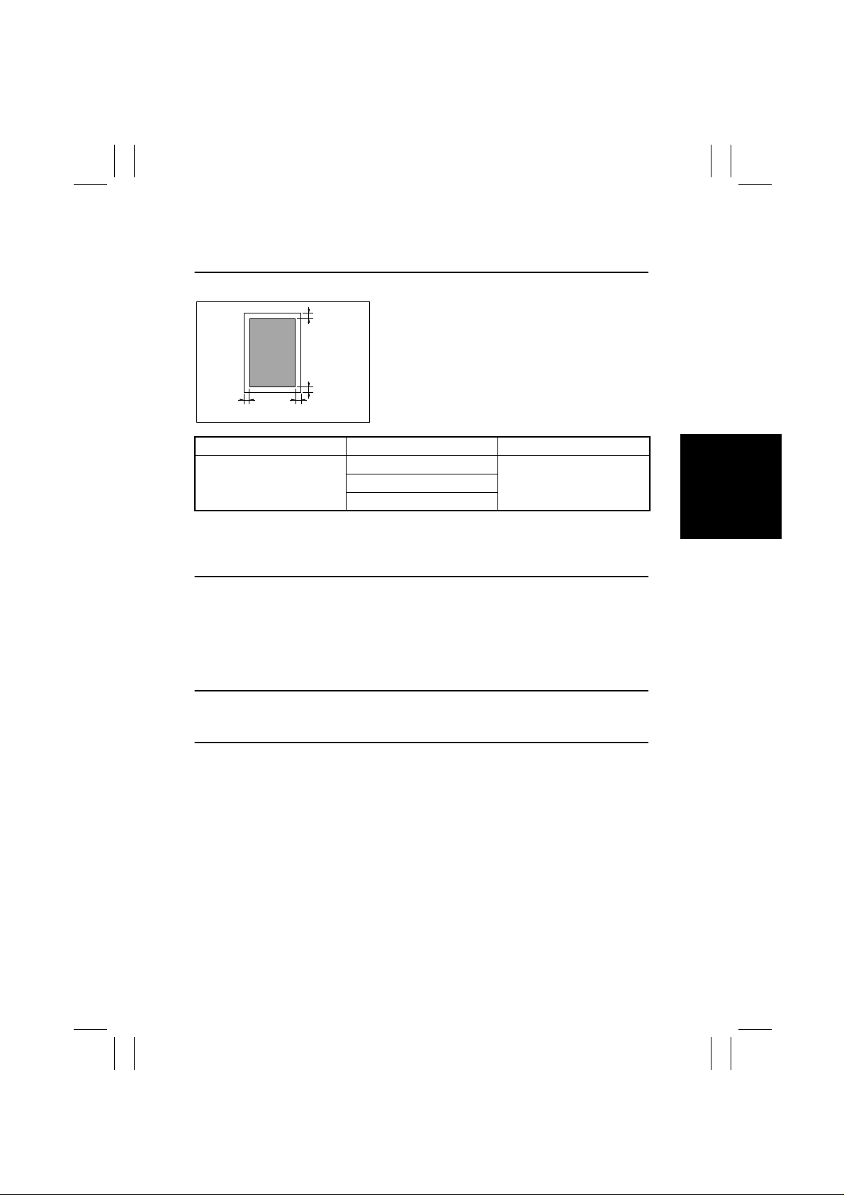
4022D503AA
• Adjust the erase width on the leading edge (width
A), trailing edge (width B), and the top/bottom edge
(width C).
✽
Default Setting: 4 mm
5 (leading edge)
0 to 5, 1 step: 1 mm6 (trailing edge)
7 (top/bottom)
<Adjustment Procedure>
1. Enter the Tech. Rep. Choice mode.
2. With “c--” shown on the Display, enter the code number “5” from the 10-Key Pad and
press the Start key to enter the “Leading Edge Erase Adjustment” mode.
3. Press the Clear key to clear the current setting value.
4. Enter the setting value from the 10-Key Pad and press the Start key to validate the
entry.
Adjustment Instructions
To make the edge erase width smaller, decrease the setting value.
To make the edge erase width greater, increase the setting value.
5. Following the same procedure, set the erase width on the trailing edge and top/bottom
edge.
D-53
 Loading...