

Page 1
FrameMaker Ver5.5E(PC) Di152/Di183 SWITCHES ON PWBs/TECH. REP. SETTINGS
01.07.26
3. TECH.REP.MODE
• This mode allows the Tech. Rep. to set adjust, and/program various service functions.
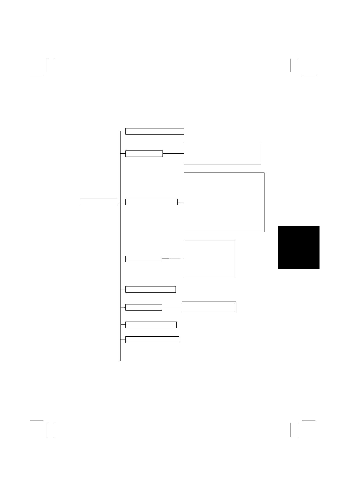
3-1. Tech.Rep.Mode Menu Function Tree
---0: Control Panel LED Check
F-1 : Paper Passage Test
F-2 : HV Output
F-8 : ATDC Sensor Automatic Adjustment
F12: Test Pattern Output
c-1 : Maintenance Counter Count
c-2 : IU Life Stop
c-3 : ID Adjustment
c-4 : VG Adjustment
c-5 : Leading Edge Erase Adjustment
c-6 : Trailing Edge Erase Adjustment
c-7 : Top/Bottom Edge Erase Adjustment
c-8 : Loop Length Adjustment (1st Tray)
c-9 : Loop Length Adjustment (2nd Tray)
c10: Loop Length Adjustment (Bypass Tray)
c11: Priority FL S Setting
---: Tech.Rep.Mode
---1: Function “F- ”
---2: Tech.Rep .Choice “c--”
---3: Counter “cnt”
---4: ATDC Sensor Output
---5: Level History
---6: ROM Version Display
---7: Administrator No. Input
~
--1: PM Counter
--2: Maintenance Counter
--3: IU Life Counter
--4: Application Counter
--5: Jam Counter
--6: Trouble Counter
--7: Paper Size Counter
Vg (grid voltage)
Vb (developing bias voltage)
S-13
Page 2

FrameMaker Ver5.5E(PC) Di152/Di183 SWITCHES ON PWBs/TECH. REP. SETTINGS
01.07.26
~
---8: Change Fixed Zoom
---9: Marketing Area Setting
-10: Memory Clear “CLr”
---: Tech.Rep.Mode
-11: Total Clear “tCL”
-12: ADF Document Passage Test “doc”
-13: ADF Original Glass Check “AdF”
-14: Scanner Drive Check “ccd”
-20: Serial No. Display “Sn”
3-2. Tech.Rep.Mode Function Setting Procedure
<Procedure>
1. Press the Meter Count key.
2. Press the following keys in this order:
Stop → 0 → 0 → Stop → 0 → 1
3. Enter the code number corresponding to the function to be used from the 10-Key Pad.
Code No.: 0 to 14,20
4. Press the Start Key.
<Exiting the Mode>
• Press the Panel Reset key until the initial screen reappears.
S-14
Page 3
FrameMaker Ver5.5E(PC) Di152/Di183 SWITCHES ON PWBs/TECH. REP. SETTINGS
01.07.26
3-3. Setting in the Tech.Rep.Mode
(1) Control Panel LED Check
• The LEDs on the control panel are made to blink to check for any LED that has burned
out.
Any LED that is not blinking is considered to be out.
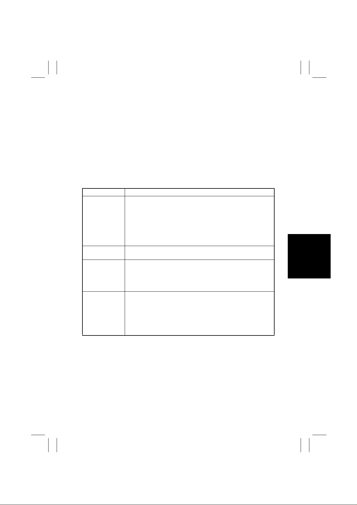
(2) Function
• This function allows the Tech. Rep. to make the various function tests and adjustments.
<Procedure>
1. Enter the code number corresponding to the function to be used from the 10-Key Pad.
2. Press the Start key.
<Exiting the Mode>
• Press the Panel Reset key until the initial screen reappears.
Code No. Operation
<Paper Passage Test>
<HV Output>
<ATDC Sensor Automatic Adjustment>
<Test Pattern Output>
F-1
F-2
F-8
F12
Correct paper passage (paper transport path) is checked without
involving any printing action.
This test is used to check for a paper misfeed and transport path.
<Procedure>
1. Select the paper source.
2. Press the Start key to start the paper passage cycle.
3. Press the Stop key to stop the paper passage cycle.
This test is for factory adjustment only and should NOT be used.
Adjusts the output level of the ATDC Sensor.
This test is used when the copier is set up, developer is changed, and
the IU is replaced.
✽
For details, see DIS/REASSEMBLY, ADJUSTME N T.
Outputs a test pattern. (Halftone)
This test is used to determine whether the engine is responsible for
an image problem which has occurred or the IR is responsible for it.
<Procedure>
1. Select the paper source.
2. Press the Start key to start the output sequence.
S-15
Page 4
FrameMaker Ver5.5E(PC) Di152/Di183 SWITCHES ON PWBs/TECH. REP. SETTINGS
Highlighted
0
01.07.26
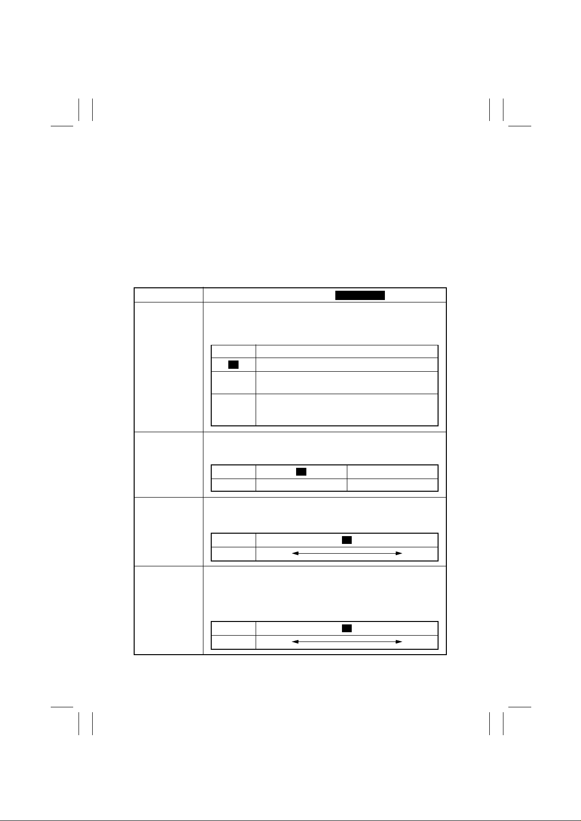
(3) Tech.Rep.Choice
• This function allows the Tech. Rep. to make various settings and adjustments.
<Procedure>
1. Enter the code number corresponding to the function to be used from the 10-Key Pad.
2. Press the Start key to display the current setting value.
3. Press the Clear key to clear the current setting value.
4. Enter the new setting value from the 10-Key Pad.
5. Press the Start key to validate the new setting value just entered.
If any value outside the available setting range is entered, the Display shows “Err”
rejecting the entry . (The old setting value will reappear on the Display 1 sec. later.)
<Exiting the Mode>
• Press the Panel Reset key until the initial screen reappears.
Code No.
C-1
C-2
C-3
C-4
Setting (The default is ).
<Maintenance Counter Count>
Select the counting method of the maintenance counter.
It is used as guidelines for the number of copies to be made before
the next maintenance time.
Setting Description
Not Count
0
Counted (Maintenance Indicator lights when a set-
1
ting value is reached.)
Counted (No new copy cycle can be initiated and
2
the Tech. Rep. Call LED lights when a setting value
is reached.)
<IU Life Stop>
Select whether to prohibit copying or not when the IU Counter
reaches a life value.
Setting 1
Description Copying allowed Copying prohibited
Set the central value of image density.
This function is used when image density is not satisfactory.
Setting
Description
Vary the Vg voltage to adjust image density.
The function is used when a fog or a void occurs.
Increase the setting value to eliminate void.
Decrease the setting value to eliminate fog.
0 1 2 4 5 6
Lighter Darker
<ID Adjustment>
3
<VG Adjustment>
Setting
Description
0 1 3 4
Lighter Darker
2
S-16
Page 5

FrameMaker Ver5.5E(PC) Di152/Di183 SWITCHES ON PWBs/TECH. REP. SETTINGS
Highlighted
01.07.26
Code No.
C-5
C-6
C-7
C-8
C-9
Setting (The default is ).
Select whether to enable or disable the leading edge erase.
Setting
Description (mm)
Select whether to enable or disable the trailing edge erase.
Setting
Description (mm)
Select the width of erase on the top and bottom edges.
Setting
Description (mm)
Adjust the length of the loop formed before the Synchronizing Roller
when a skew or misfeed occurs. (1st Tray)
Setting
Description (mm)
Adjust the length of the loop formed before the Synchronizing Roller
when a skew or misfeed occurs. (2nd Tray)
Setting
Description (mm)
<Leading Edge Erase Adjustment>
0 1 2 3 5
05
<Trailing Edge Erase Adjustment>
0 1 2 3 5
05
<Top/Bottom Edge Erase Adjustment >
0 1 2 3 5
05
<Loop Length Adjustment (1st Tray)>
0................................. .......................... 14
-3.9 +3.9
<Loop Length Adjustment (2nd T ray)>
0................................. .......................... 14
-3.9 +3.9
7
7
4
4
4
C10
C11
Adjust the length of the loop formed before the Synchronizing Roller
when a skew or misfeed occurs. (Bypass Tray)
Description (mm)
Set the size for FLS.
Setting Description
<Loop Length Adjustment (Bypass Tray)>
Setting
0 330×203
1
2 330×216
3 330×220
4 337×206
0................................. .......................... 14
-3.9 +3.9
<Priority FLS Set t ing>
330×210
7
S-17
Page 6

FrameMaker Ver5.5E(PC) Di152/Di183 SWITCHES ON PWBs/TECH. REP. SETTINGS
01.07.26
(4) Coun ter Mode
• Shows the number of copies made on each paper size or type.
<Procedure>
1. Enter the code number corresponding to the function to be used from the 10-Key Pad.
2. Press the Start key to show the count.
If the count consists of 4 or more digits, it is displayed in two groups alternately as follows.
E.g.: “123” and “456” alternate if the count is 123,456.
3. Press the Paper key to select the display of another counter.
4. Call the counter count to be cleared on the Display.
5. Press the Clear Key.
Press Interrupt key to undo the clearing operation, restoring the original setting.
6. Press the Start Key.
<Exiting the Mode>
• Press the Panel Reset key until the initial screen reappears.
Code No. Setting
<PM Counter>
Counts the frequency of use of each of the different parts of the
copier.
The count should be cleared when the corresponding PM part is
replaced.
--1
Display Description Display Description
1
2
3
4
5
Bypass Tray
1st Tray
2nd Tray
3rd Tray
4th Tray
6
5th Tray
7
ADF
8
IR
9
Ozone Filter
10
Image Transfer Roller/Fusing Unit
--2
Enter a value for the maintenance counter (for any given part).
<Maintenance Counter>
The count is based on a countdown system and when the set value is
counted down to “0,” the Maintenance Indicator lights.
If counting continues after “0,” a minus sign (-) is appended to the
value shown on the Display.
NOTE
• The above counting method varies depending on the setting made
for “c-1” of Tech. Rep. Choice.
The Display shows “nc1” if copying is prohibited.
<Procedure>
1. Press the Start key to display the current count.
2. Press the Clear key to clear the current count.
If the current count is mistakenly cleared, press the Interrupt key
to restore the count just cleared.
3. Enter the new value from the 10-K ey Pad (that can range from 0 to
999999).
4. Press the Start key to validate the new setting just made.
S-18
Page 7

FrameMaker Ver5.5E(PC) Di152/Di183 SWITCHES ON PWBs/TECH. REP. SETTINGS
01.07.26
Code No. Setting
<IU Life Counter>
--3
Show the count of the IU Life Counter.
The count is based on a countdown system and, if counting continues
after “0,” a minus sign (-) is appended to the value shown on the Display.
The count is controlled according to the period of time through which
the PC Drum has turned and, when a near-life value is reached, the
Maintenance Indicator blinks.
<Procedure>
1. Press the Start key to display the current count.
2. Press the Clear key to clear the current count.
If the current count is mistakenly cleared, press the Interrupt key
to restore the count just cleared.
3. Press the Start key to automatically set “40,000.” (The value
“40,000” is the starting value from which it is counted down.)
✽
No value can be set from the 10-Key Pad.
NOTES
• There are some discrepancies between the count and the actual
number of copies made.
• The setting made in “c-2” of Tech. Rep. Choice determines the
copying operation after the life value has been reached.
If “Copying prohibited” is selected, “nc2” is displayed and the Maintenance Indicator lights steadily.
--4
--5
<Application Counter>
The count is made according to the application..
Display Description
12No. of copies made.
No. of printed pages produced through PC
<Jam Counter>
Counts the number of misfeeds that have occurred at different locations in the copier.
Display Desc ription
1
Bypass Tray
2
1st Tray
3
2nd Tray
4
3rd Tray
5
4th Tray
6
5th Tray
7
Paper take-up and vertical transport
8
Separator
9
Fusing Unit
10
ADF take-up
11
ADF transport
12
ADF exit
S-19
Page 8

FrameMaker Ver5.5E(PC) Di152/Di183 SWITCHES ON PWBs/TECH. REP. SETTINGS
01.07.26
Code No. Setting
<Trouble Counter>
--6
Counts the number of malfunctions that have occurred at different
parts of the copier.
If all malfunction counters are “0,” “ALL” and “0” alternate.
Display Description
1
Main Motor malfunction
2
Fusing Cooling Fan Motor malfunction
3
Power Supply Cooling Fan Motor malfunction
4
Toner Replenishing Motor malfunction
5
Faulty image transfer voltage
6
Warm-up failure
7
Abnormally low fusing temperature
8
Abnormally high fusing temperature
9
Scanner Home Sensor malfunction
10
Tray Selecting Motor malfunction
11
Shift Motor malfunction
12
ATDC Sensor malfunction
13
ATDC adjustment failure
14
ASIC/memory malfunction
15
Polygon Motor malfunction
16
HSYNC detection failure
17
EEPROM malfunction
18
Exposure Lamp malfunction
--7
Counts the number of sheets of paper used according to the size and
type.
Display Description
1
A3 (L)
2
B4 (L)
3
A4 (L)
4
A4 (C)
5
B5 (L)
6
B5 (C)
7
A5 (L)
8
A5 (C)
9
FLS (L)
10
Ledger (L)
11
11×14 (L)
12
Legal (L)
<Paper Size Counter>
Display Description
13
Letter (L)
14
Letter (C)
15
Invoice (L)
16
Invoice (C)
17
Other size
18
Paper enabling A uto Paper/
enabling auto tray switching
19
Paper disabling Auto Paper/
enabling auto tray switching
20
Paper disabling Auto Paper/
disabling auto tray s witching
21
OHP
22
Thick paper
S-20
Page 9

FrameMaker Ver5.5E(PC) Di152/Di183 SWITCHES ON PWBs/TECH. REP. SETTINGS
01.07.26
(5) ATDC Sensor Output
• This function displays a T/C ratio representing the current ATDC Sensor output value.
• It is used for checking the T/C when image density is not good.
✽
It is not possible to change or reset the sensor output data.
<Exiting the Mode>
• Press the Panel Reset key until the initial screen reappears.
(6) Level History
• This function displays the grid voltage and developing bias voltage .
✽
It is not possible to change or reset the voltage data.
<Procedure>
1. Press the Start key to display the current grid voltage (Vg).
2. Press the Zoom “down” key to display the current developing bias voltage (Vb).
Press the Zoom “up” key to return to the display of the current grid voltage (Vg).
<Exiting the Mode>
• Press the Panel Reset key until the initial screen reappears.
(7) ROM Version
• This function displays the ROM version.
• It is used when upgrading the F/W or the PWB is replaced with a new one.
• The version is displayed in the order of the copier controller and engine.
• The version consists of 12 digits, each being displayed sequentially as the image density
key (darker) (the digits flow in the left direction).
<Procedure>
1. Press the Start key to display the first 3 digits of the total 12.
2. Press the image density key (darker). Then, the leftmost digit will disappear and,
instead, a new fourth digit will appear.
Press the image density key (darker) a number of times to view the entire digits of the
version.
✽
Pressing the image density key (lighter) will reverse the display of digits.
3. Press the Zoom “down” key to display the version of the engine ROM.
Follow the same steps as those given above.
✽
Pressing the Zoom “up” or “down” key selects the display of the ROM version of the
copier controller or engine.
<Exiting the Mode>
• Press the Panel Reset key until the initial screen reappears.
S-21
Page 10

FrameMaker Ver5.5E(PC) Di152/Di183 SWITCHES ON PWBs/TECH. REP. SETTINGS
01.07.26
(8) Administrator No. In p ut
• Set an ID number for opening the “Administrator Mode” screen of Utility Mode from the
10-Key P ad.
<Procedure>
1. Press the Start key to alternately display the current administrator number.
2. Press the Clear key to clear the current administrator number.
3. Enter the new administrator number from the 10-Key Pad. The number should consist
of 6 digits, ranging from 000000 to 999999.
4. Press the Start key to validate the new administrator number just entered.
(9) Change Fixed Zoom
• Change a fixed zoom ratio to a desired value.
✽
The ratios of 50 %, 100 %, and 200 % cannot be changed.
<Procedure>
1. Press the Start key to display the fixed zoom ratio.
2. Press the Zoom key to select the specific zoom ratio to be changed.
3. Press the Clear key to clear the zoom ratio selected.
4. Enter the new zoom ratio from the 10-Key Pad.
5. Press the Start key to validate the new zoom ratio just entered.
If any value outside the allowable setting range is entered, the Display shows “Err”
rejecting the entry . (The old zoom ratio will reappear on the Display 1 sec. later.)
(10) Marketing Area Setting
• Set the marketing area.
<Procedure>
1. Press the Start key to display the current marketing area setting.
Setting Description
0MSJ
1MC
2ME
3 China
4 Other areas
2. Press the Clear key to clear the current marketing area setting value.
3. Enter the new setting value from the 10-Key Pad.
4. Press the Start key to validate the setting value just entered.
If any value outside the available setting range is entered, the Display shows “Err”
rejecting the entry . (The old setting value will reappear on the Display 1 sec. later.)
S-22
Page 11

FrameMaker Ver5.5E(PC) Di152/Di183 SWITCHES ON PWBs/TECH. REP. SETTINGS
01.07.26
(11) Memory Clear
• This function is used to clear all data except that of the various electronic counters.
<Procedure>
1. Press the Start key to display “CLr” on the Display.
2. Press the Start key to blank out the Display.
Then, “CLr” will reappear.
3. Turn O FF and ON the Power Switch.
(12) Total Clear
• This function is used to clear all data of the various electronic counters.
<Procedure>
1. Press the Start key to display “tCL” on the Display.
2. Press the Start key to blank out the Display.
Then, “tCL” will reappear.
3. Turn O FF and ON the Power Switch.
<List of Types of Data to be Cleared>
Clearing
Data Cleared
Jam dis play
Trouble display —
Erratic operation/display —
Utility (*1) —
Tech.Rep.Mode (*2) —
Security —
Adjust —
Job programs —
Electronic counters — —
❍
: Cleared —: Not cleared
*1: Except Copy Track, Input Account, and Total Counter Display by Account.
*2: Except Marketing Area Setting and Serial No. Display.
Door
Open/Close
❍❍
Memory
Clear
❍
❍
❍
❍
❍
❍
❍
Total
Clear
—
—
—
—
—
—
—
—
❍
(13) ADF Document Passage Test
• This function is used to check for correct document passage through the ADF when a
document misfeed occurs.
<Procedure>
1. Load a paper stack in the Document Feeding Tray.
2. Press the Start key to let the ADF start feeding the paper.
3. Press the Stop key to stop the sequence.
✽
For details, see the relevant option service manual.
S-23
Page 12

FrameMaker Ver5.5E(PC) Di152/Di183 SWITCHES ON PWBs/TECH. REP. SETTINGS
01.07.26
(14) ADF Original Glass Check
• The original scanning area of the ADF is scanned to check for possible dirt or scratches
on the glass. The scanned area is produced as a copy.
<Procedure>
• Press the Start key to start the sequence.
✽
For details, see the relevant option service manual.
(15) Scanner Move Check
• This function is used to check the drive for the Scanner.
• It is also used when securing the Scanner in position with the fixing pin (for transportation
of the machine).
<Procedure>
• Press the Start key. This will move the Scanner to the left and stop.
(16) Serial No. Display
• This function is used to display the serial number (consisting of 8 digits).
<Procedure>
• Press the Start key to display the serial number.
E.g.: The Display shows “Sn” → “12” → “345” → “678” in that order if the serial number is
12345678.
S-24
 Loading...