

Page 1
FrameMaker Ver5.5E(PC) Di152/Di183 SWITCHES ON PWBs/TECH. REP. SETTINGS
Highlighted
0
01.07.26
(3) Tech.Rep.Choice
• This function allows the Tech. Rep. to make various settings and adjustments.
<Procedure>
1. Enter the code number corresponding to the function to be used from the 10-Key Pad.
2. Press the Start key to display the current setting value.
3. Press the Clear key to clear the current setting value.
4. Enter the new setting value from the 10-Key Pad.
5. Press the Start key to validate the new setting value just entered.
If any value outside the available setting range is entered, the Display shows “Err”
rejecting the entry . (The old setting value will reappear on the Display 1 sec. later.)
<Exiting the Mode>
• Press the Panel Reset key until the initial screen reappears.
Code No.
C-1
C-2
C-3
C-4
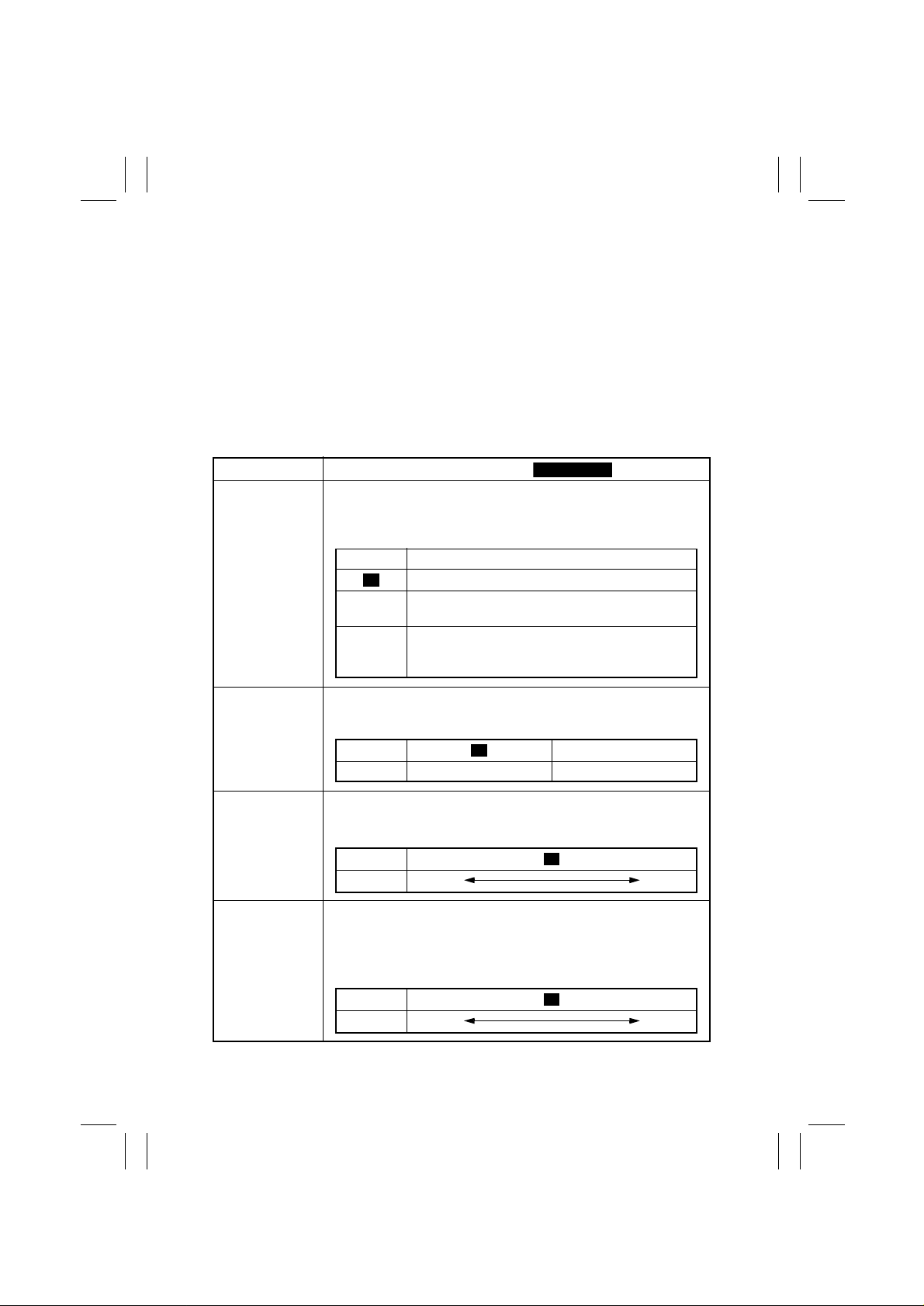
Setting (The default is ).
<Maintenance Counter Count>
Select the counting method of the maintenance counter.
It is used as guidelines for the number of copies to be made before
the next maintenance time.
Setting Description
Not Count
0
Counted (Maintenance Indicator lights when a set-
1
ting value is reached.)
Counted (No new copy cycle can be initiated and
2
the Tech. Rep. Call LED lights when a setting value
is reached.)
<IU Life Stop>
Select whether to prohibit copying or not when the IU Counter
reaches a life value.
Setting 1
Description Copying allowed Copying prohibited
Set the central value of image density.
This function is used when image density is not satisfactory.
Setting
Description
Vary the Vg voltage to adjust image density.
The function is used when a fog or a void occurs.
Increase the setting value to eliminate void.
Decrease the setting value to eliminate fog.
0 1 2 4 5 6
Lighter Darker
<ID Adjustment>
3
<VG Adjustment>
Setting
Description
0 1 3 4
Lighter Darker
2
S-16
Page 2
FrameMaker Ver5.5E(PC) Di152/Di183 SWITCHES ON PWBs/TECH. REP. SETTINGS
Highlighted
01.07.26
Code No.
C-5
C-6
C-7
C-8
C-9
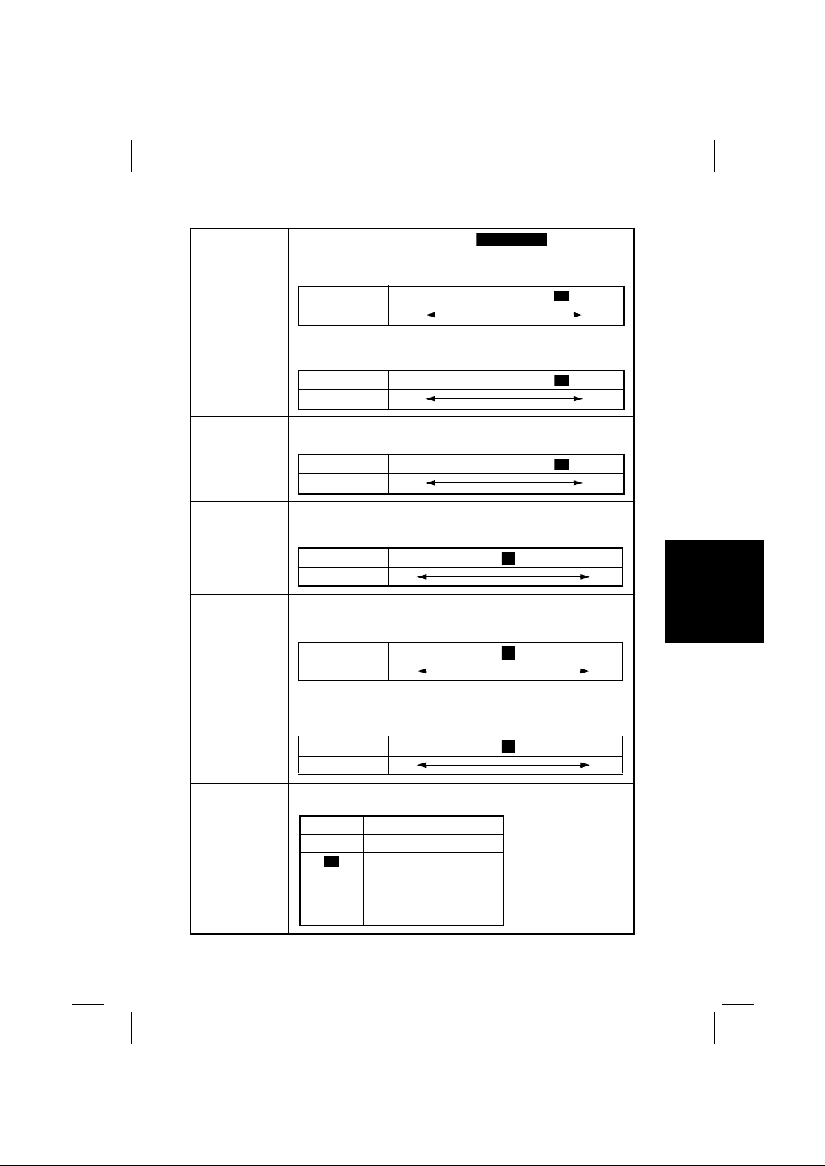
Setting (The default is ).
Select whether to enable or disable the leading edge erase.
Setting
Description (mm)
Select whether to enable or disable the trailing edge erase.
Setting
Description (mm)
Select the width of erase on the top and bottom edges.
Setting
Description (mm)
Adjust the length of the loop formed before the Synchronizing Roller
when a skew or misfeed occurs. (1st Tray)
Setting
Description (mm)
Adjust the length of the loop formed before the Synchronizing Roller
when a skew or misfeed occurs. (2nd Tray)
Setting
Description (mm)
<Leading Edge Erase Adjustment>
0 1 2 3 5
05
<Trailing Edge Erase Adjustment>
0 1 2 3 5
05
<Top/Bottom Edge Erase Adjustment>
0 1 2 3 5
05
<Loop Length Adjustment (1st Tray)>
0................................. .......................... 14
-3.9 +3.9
<Loop Length Adjustment (2nd T ray)>
0................................. .......................... 14
-3.9 +3.9
7
7
4
4
4
C10
C11
Adjust the length of the loop formed before the Synchronizing Roller
when a skew or misfeed occurs. (Bypass Tray)
Description (mm)
Set the size for FLS.
Setting Description
<Loop Length Adjustment (Bypass Tray)>
Setting
0 330×203
1
2 330×216
3 330×220
4 337×206
0................................. .......................... 14
-3.9 +3.9
<Priority FLS Set t ing>
330×210
7
S-17
 Loading...