

Page 1
FrameMaker Ver.5.5E(PC) Di152/Di183 TROUBLESHOOTING
01.09.04
4. MALFUNCTION
The copier’s CPU is equipped with a self-diagnostics function that, on detecting a malfunction, gives the corresponding malfunction code on the Display.
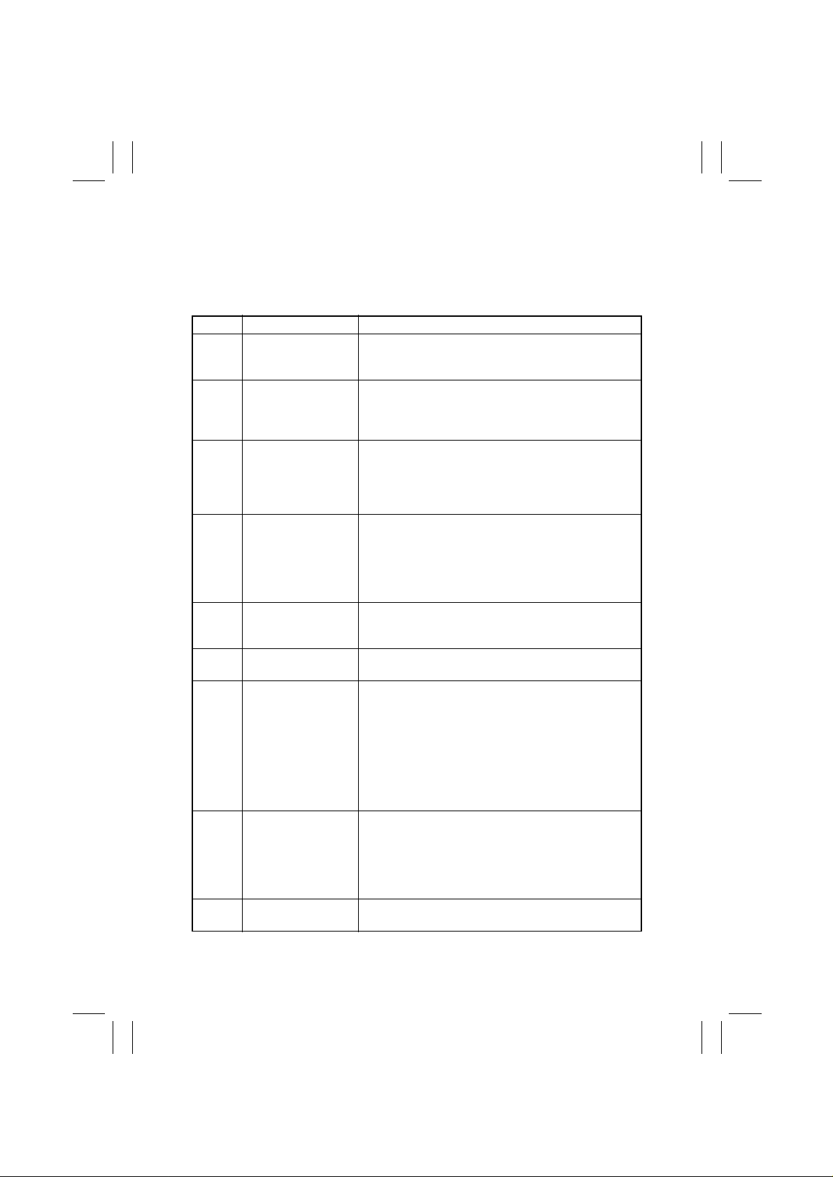
4-1. Detection Timing by Malfunction Code
Code Description Detection Timing
C0000 Main Motor malfunc-
tion
C0045 Fusing Cooling Fan
Motor malfunction
C004E Power Supply Cool-
ing Fan Motor malfunction
C0070 Toner Replenishing
Motor malfunction
C0210 Abnormal image
transfer voltage
C03FF Improperly set Adjust
Mode 11
C0500 Warm-up failure • It takes the surface temperature of the Left Fusing
C0510 Abnormally low fus-
ing temperature
C0520 Abnormally high fus-
ing temperature
• The Main Motor (M1) Lock signal remains HIGH for a
continuous 1-sec. period at any time 1 sec. after the
Main Motor has started turning.
• The Fusing Cooling Fan Motor (M3) Lock signal
remains HIGH for a continuous 1-sec. period while the
Fusing Cooling Fan Motor is turning at full speed or
decelerated speed.
• The Power Supply Cooling Fan Motor (M4) Lock signal remains HIGH for a continuous 1-sec. period while
the Pow er Supply Cooling Fan Motor Remote signal
remains ON (for full-speed rotation) or OFF (for decelerated-speed rotation).
• The Toner Bottle Home P osition Sensor (PC7) outputs
a HIGH signal for a continuous 3.5-sec. period while
the Toner Bottle is turning.
• The Toner Bottle Home P osition Sensor (PC7) outputs
a LOW signal f or a continuous 2-sec. period while the
Toner Bottle is turning.
• The image transfer voltage remains more than 100 V
for a continuous given period of time while the PC
Drum remains stationary.
• An incorrect setting is made of Adjust 11.
Roller more than 35 sec. to reach 100 °C since the
start of a warm-up cycle.
• It takes the surface temperature of the Left Fusing
Roller more than 25 sec. to reach 140 °C after it has
reached 100 °C.
• It takes more than 20 sec. for the warm-up cycle to be
completed after the surface temperature of the Left
Fusing Roller has reached 140 °C.
• The surface temperature of the Left Fusing Roller
remains lower than 120 °C for a given period of time
while the copier is in a standby state.
• The surface temperature of the Left Fusing Roller
remains lower than 120 °C for a given period of time
during a print cycle.
The surface temperature of the Left Fusing Roller
remains higher than 240 °C for a given period of time.
T-18
Page 2
FrameMaker Ver.5.5E(PC) Di152/Di183 TROUBLESHOOTING
01.09.04
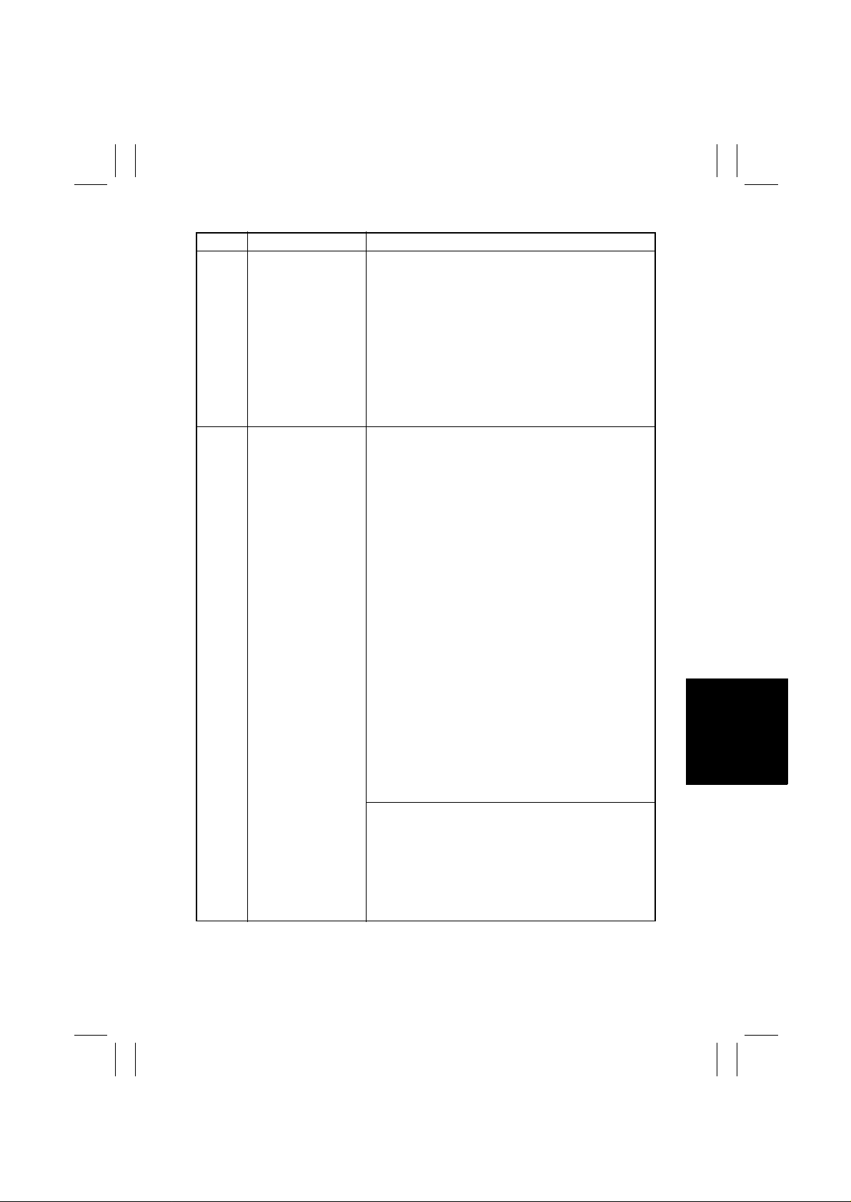
Code Description Detection Timing
C0650 Faulty Scanner Home
Position Sensor
C0B60 Bin Switching Motor
malfunction
• The Scanner Home Position Sensor (PC6) does not
go from HIGH to LOW when the Scanner Motor (M5)
is energized for a given number of steps after the
sequence to bring the Scanner back to its home position has been started at the end of a scan motion and
during re-shading.
• The Scanner Home Position Sensor (PC6) does not
go from LOW to HIGH when the Scanner Motor (M5)
is energized for a given number of steps after a scan
motion has been started at the end of a Scanner
Home Position Sensor home check scan motion and
during re-shading.
If the Upper Home Position Sensor is LOW during an initial operation:
• The Lower Home Position Sensor (PC33) is LOW
when the Bin Switching Motor (M1) starts turning forward.
• If the Lower Home Position Sensor (PC33) does not
go LOW at a time 2.5 sec. after the Bin Switching
Motor (M1) has started turning forward, the Bin
Switching Motor is kept deenergized for a given
period of time and then energized again to turn backward. The Upper Home Position Sensor (PC32) does
not go LOW after the motor has started turning backward.
• The Upper Home Position Sensor (PC32) does not go
HIGH at a time 1 sec. after the Bin Switching Motor
(M1) has started turning forward.
• When the Lower Home Position Sensor (PC33) goes
LOW, the Bin Switching Motor (M1) starts turning
backward. The Upper Home Position Sensor (PC32)
does not go LOW at a time 2.5 sec. after the motor
has started turning backward.
• When the Lower Home Position Sensor (PC33) goes
LOW, the Bin Switching Motor (M1) starts turning
backward. The Lower Home Position Sensor (PC33)
does not go HIGH at a time 1 sec. after the motor has
started turning backward.
If the Lower Home Position Sensor is LOW during an initial operation:
• The Upper Home Position Sensor (PC32) does not go
LOW at a time 2.5 sec. after the Bin Switching Motor
(M1) has started turning backward.
• The Lower Home Position Sensor (PC33) does not go
HIGH at a time 1 sec. after the Bin Switching Motor
(M1) has started turning backward.
T-19
Page 3

FrameMaker Ver.5.5E(PC) Di152/Di183 TROUBLESHOOTING
01.09.04
Code Description Detection Timing
C0B60 Bin Switching Motor
malfunction
C0B80 Shift Motor malfunc-
tion
C0F32 Faulty ATDC Sensor • The measurement taken by the ATDC Sensor (UN1)
C0F33 Improperly adjusted
ATDC Sens or
C1038 Engine connection
failure
If both the Upper Home Position Sensor and the Lower
Home Position Sensor are HIGH during an initial operation:
• If the Lower Home Position Sensor (PC33) does not
go LOW at a time 2.5 sec. after the Bin Switching
Motor (M1) has started turning forward, the Bin
Switching Motor is kept deenergized for a given
period of time and then energized again to turn backward. The Upper Home Position Sensor (PC32) does
not go LOW after the motor has started turning backward.
• When the Lower Home Position Sensor (PC33) goes
LOW, the Bin Switching Motor (M1) starts turning
backward. The Upper Home Position Sensor (PC32)
does not go LOW at a time 2.5 sec. after the motor
has started turning backward.
• When the Lower Home Position Sensor (PC33) goes
LOW, the Bin Switching Motor (M1) starts turning
backward. The Lower Home Position Sensor (PC33)
does not go HIGH at a time 1 sec. after the motor has
started turning backward.
• The Home Sensor (S31) is LOW at a timing immediately before the Shift Motor (M1) starts turning backward.
• The Home Sensor (S31) is LOW after the lapse of a
given period of time after the Shift Motor (M1) has
started turning backward.
at a time 2.5 sec. after the Main Motor (M1) has
started turning is less than 3 % (greater than 4.98 V).
• The measurement taken by the ATDC Sensor (UN1)
at a time 2.5 sec. after the Main Motor (M1) has
started turning is 19 % or more (1.41 V or less).
• The adjustment of the ATDC control voltage is not
completed within 1 sec. after sampling has started of
the ATDC Sensor (UN1) as part of an operation of
ATDC Sensor Automatic Adjustment.
• The ATDC Sensor control voltage falls outside the
range of 5.39 V to 8.15 V during an operation of ATDC
Sensor Automatic Adjustment.
Master Board (PWB-A) to Control Board (PWB-C) connection failure
• There is no acknowledge signal transmitted from the
Master Board (PWB-A) to Control Board (PWB-C) for
1.5 sec. or more.
• An error command signal is transmitted from the Control Board (PWB-C) to Master Board (PWB-A).
• An error status signal is transmitted from the Master
Board (PWB-A) to Control Board (PWB-C).
T-20
Page 4

FrameMaker Ver.5.5E(PC) Di152/Di183 TROUBLESHOOTING
01.09.04
Code Description Detection Timing
C1200 Faulty ASIC/memory ASIC/memory (for image and control) fault
• A write or read error occurs with SRAM on the Control
Board (PWB-C).
C1300 Polygon Motor mal-
function
C13F0 Fault y HSYNC Laser scanning system malfunction
C1468 Faulty EEPROM EEPROM fault
C14A3 IR fluorescent lamp
fault
Startup failure
• A LOW Polygon Motor (M2) Lock signal is not
detected within a given period of time that begins 1
sec. after the Polygon Motor has started turning.
Lock signal fault: Unstable aft er the fi rst Lock signal has
been detected
• For a period of 1 sec. after the first LOW Polygon
Motor (M2) Lock signal (first Lock) has been detected,
the next LOW Polygon Motor Lock signal is not
detected.
Lock signal fault: Lock signal out-of-timing
• A LOW Polygon Motor (M2) Lock signal is not
detected for a continuous given period of time while
the rotation of the Polygon Motor remains stabilized.
Faulty Lock signal
• A LOW Polygon Motor (M2) Lock signal is detected for
a given period of time or more when the Polygon
Motor remains deenergized.
• The SOS Sensor does not detect a rising edge of
SOS within a given period of time after the Polygon
Motor (M2) has started turning and a laser output has
been started.
• The SOS Sensor detects no rising edges of SOS
while VIA (image area control) is ON.
• Data cannot be written in EEPROM.
• Data stored in EEPROM is wrong.
The Exposure Lamp (LA2) of the Scanner fails to turn
ON.
• The intensity of the Exposure Lamp is a predetermined value or less during shading and re-shading.
T-21
Page 5

FrameMaker Ver.5.5E(PC) Di152/Di183 TROUBLESHOOTING
01.09.04
4-2. Resetting Procedure by Malfunction Code
Code Description Resetting Procedure
C0000 Main Motor malfunction • Turn OFF and ON the Power Switch.
C0045 Fusing Cooling Fan Motor mal-
C004E Power Supply Cooling Fan Motor
C0070 Toner Replenishing Motor mal-
C0210 Abnormal image transfer voltage
C03FF Improperly set Adjust Mode 11 • Set Adjust Mode 11 correctly and then
C0500 Warm-up failure • Turn ON the Power Switch with the Stop
C0510 Abnormally low fusing temperature
C0520 Abnormally high fusing tempera-
C0650 Faulty Scanner Home Position
C0B60 Bin Switching Motor malfunction
C0F32 Faulty ATDC Sensor
C0F33 Improperly adjusted ATDC Sensor
C1038 Engine connection failure
C1200 Faulty ASIC/memory
C1300 Polygon Motor malfunction
C13F0 Faulty HSYNC
C1468 Fault y EEPROM
C14A3 IR fluorescent lamp fault
function
malfunction
function
turn OFF and ON the Power Switch.
• For details, see SWITCHES ON PWBs/
TECH. REP. SETTINGS.
key held down.
ture
• Turn OFF and ON the Power Switch.
Sensor
T-22
 Loading...