

Page 1
4688-7744-01.fm Page 0 Tuesday, July 31, 2001 1:12 PM
SETUP INSTRUCTIONS
Automatic Document Feeder
AF-10
NOTES
•Before setting up, be sure to unplug the power cord of the machine.
•Keep all packing materials out of the reach of children.
4688-7744-01 Printed in China
Page 2
4688-7744-01.fm Page 1 Tuesday, July 31, 2001 1:12 PM
■
Components
1. Check that the following items are available.
1. Automatic Document Feeder..... ............................... ...... ..... ..... ..... ........1
2. Setting-up Instructions........................................................................... 1
■
Installation of the Automatic Document Feeder
4695U001AA
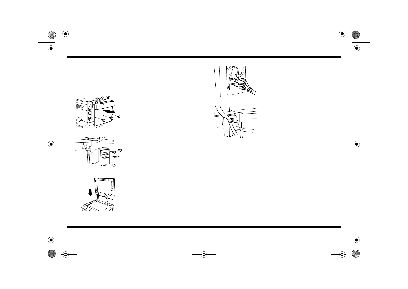
1. Remove the Rear Cover. (6 screws)
AF-10
4. Plug in three connectors.
4688U028AA
5. Secure the cable using the snap band.
6. Reinstall the parts which have been
removed.
4688U027AA
4688U026AA
4688-7744-01
2. Remove the Ornamental Cover. (3 screws)
3. Position the Automatic Document Feeder.
4688U029AA
– 1 –
Page 3
NOTE
4688-7744-01.fm Page 2 Tuesday, July 31, 2001 1:12 PM
■
Height Adjustment
4688U031AA
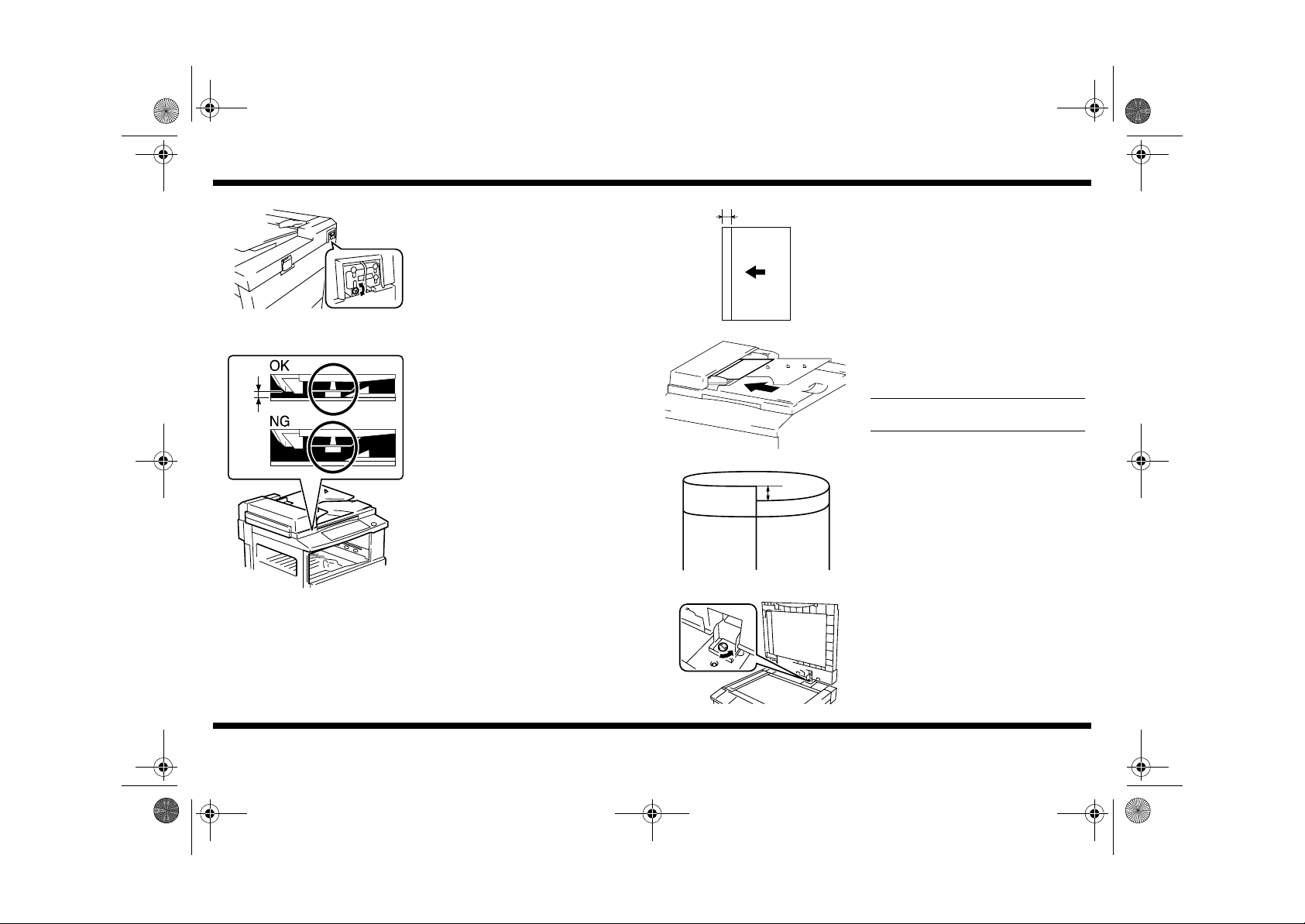
1. Turn the screw shown in the illustration as
necessary so that the spacer contacts the
glass at the scale of the machine.
Screw
Turning it clockwise will raise the Automatic
Document Feeder.
Turning it counterclockwise will lower the
Automatic Document Feeder.
AF-10
■
Skew Feed Adjustment
4688U042AA
20 mm
1. Ready a test chart (A4 or Letter) as shown.
2. Load the test chart in the Automatic
Document Feeder and make one 1-sided
copy five consecutive times.
within 0.5 mm
4688U203AD
4688-7744-01
Load the test chart crosswise.
4688U003AA
3. Fold each of the sample copies as illustrated
and check for any deviation.
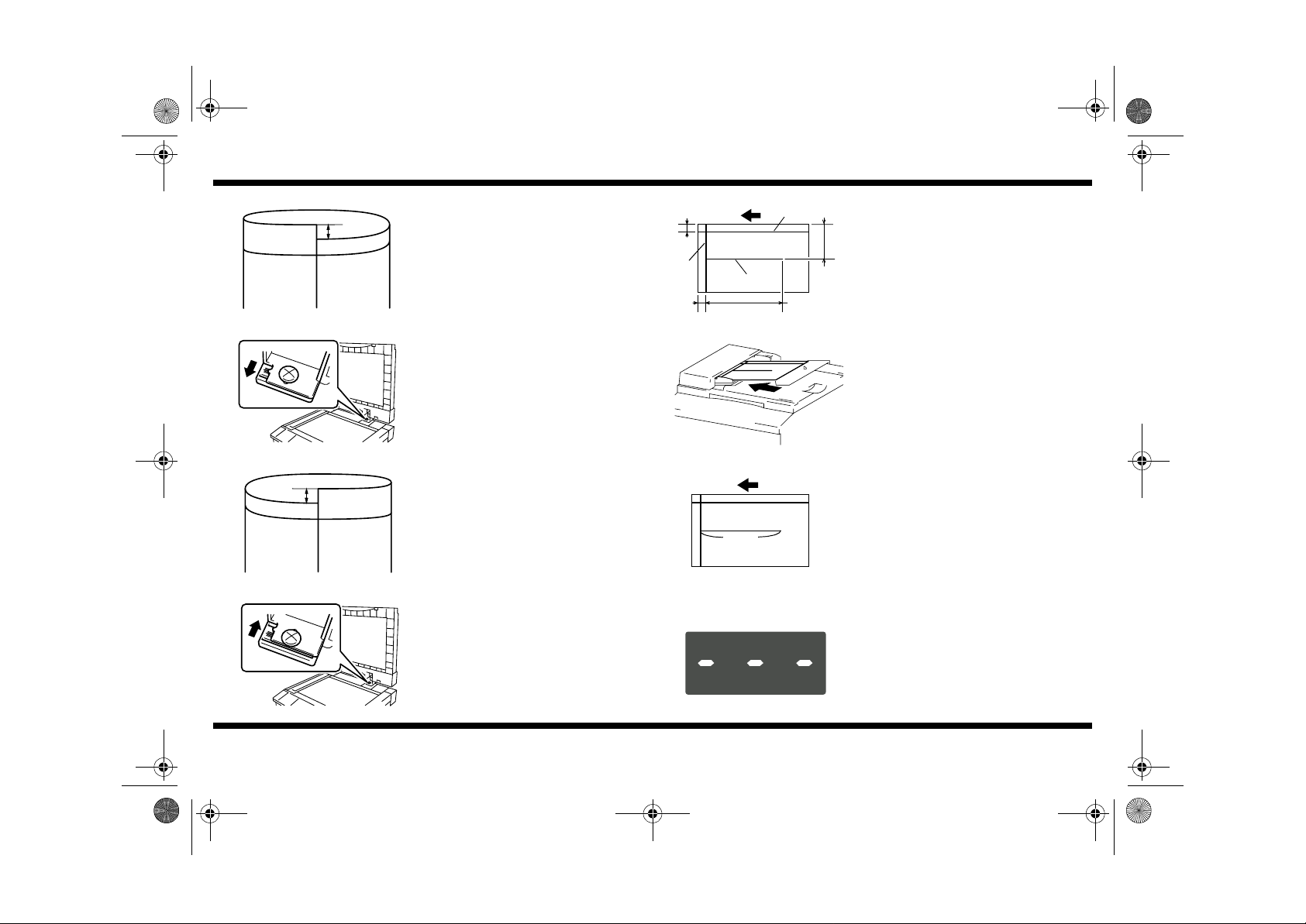
4. If the deviation is excessive, perform the
following adjustment procedure.
Specifications: 0 ± 3.0 mm
4688U001AB
5. Loosen the screw shown and adjust the
position of the Automatic Document Feeder
as detailed below.
4688U030AB
– 2 –
Page 4
4688-7744-01.fm Page 3 Tuesday, July 31, 2001 1:12 PM
6. If the deviation looks as illustrated, push the
front left side of the Automatic Document
Feeder toward the rear.
4688U001AB
AF-10
■
Zoom Ratio Adjustment and Registration Adjustment
20 mm
(C)
20 mm
4688U043AA
(A)
300 mm
(B)
1. Ready a test chart (A3 or 11x17) as shown.
(A):Draw a 300-mm-long line at a point 20
150 mm
mm from the left edge and 150 mm from
the top edge.
(B):Draw a reference line at a point 20 mm
from the top edge.
(C):Draw a reference line at a point 20 mm
from the left edge.
2. Load the test chart in the Automatic
Document Feeder and make a full-size copy.
4688U206AA
4688U002AB
4688U207AA
4688-7744-01
7. If the deviation looks as illustrated, push the
front right side of the Automatic Docume nt
Feeder toward the rear.
8. After the adjustment procedure has been
completed, tighten the screw which has been
loosened in step 5.
4688U004AA
4688U201AA
4688U032AA
– 3 –
(A)
<Zoom Ratio Adjustment>
3. Measure dimension (A) on the copy.
Specifications: 300 ± 4.5 mm
4. If dimension (A) falls outside the specified
range, perform the following adjustment
procedure.
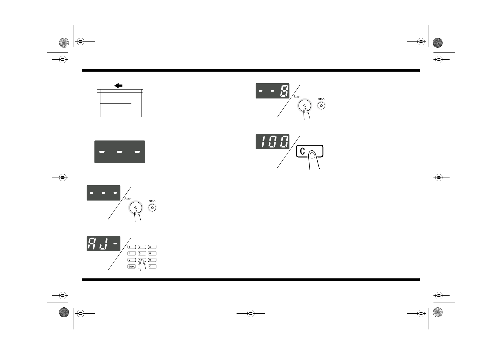
5. Call the Service mode to the Display. (For
the procedure to call the Service mode to the
Display, see the Service Manual.)
Page 5

4688-7744-01.fm Page 4 Tuesday, July 31, 2001 1:12 PM
AF-10
4688U032AA 4686U010CA
4688U033AA 4021O109AA
4688U034AA 4686U010CA
6. Press the Stop key and then immediately
press the Start key to call the Adjust mode to
the Display.
7. Using the 10-Key Pad, enter “7.”
8. Press the Start key.
9. Press the Clear key.
10.Using the 10-Key Pad, enter the setting
value. Study the table given below for the
appropriate setting value.
If dimension (A) is greater than the speci-
•
fied range, decrease the setting value.
If dimension (A) is smaller than the speci-
•
4688U036AA 4021O109AA
fied range, increase the setting value.
Setting Value Detail Setting Value Detail
87 94.8% 101 100.4%
88 95.2% 102 100.8%
89 95.6% 103 101.2%
90 96.0% 104 101.6%
91 96.4% 105 102.0%
92 96.8% 106 102.4%
93 97.2% 107 102.8%
94 97.6% 108 103.2%
95 98.0% 109 103.6%
96 98.4% 110 104.0%
97 98.8% 111 104.4%
98 99.2% 112 104.8%
99 99.6% 113 105.2%
100 100.0%
11.After the setting value has been entered,
press the Start key.
12.Make a copy and check again.
4688U035AA 4021O121AA
4688-7744-01
4688U037AA 4686U010CA
– 4 –
Page 6
4688-7744-01.fm Page 5 Tuesday, July 31, 2001 1:12 PM
■
CD Registration Adjustment
1. Measure dimension ( B) on the copy.
(B)
Specifications: 20 ± 2.0 mm
2. If dimension (B) falls outside the specified
range, perform the following adjustment
procedure.
4688U201AA
AF-10
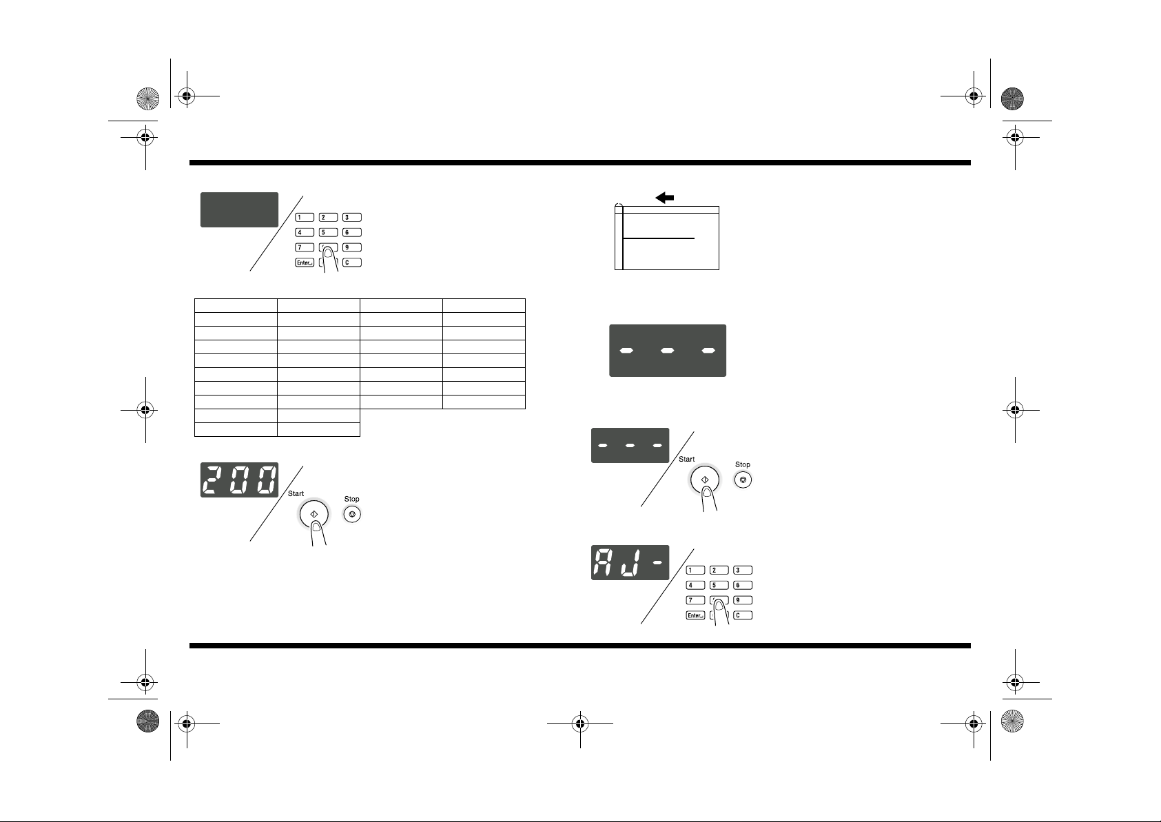
6. Press the Start key.
4688U038AA 4686U010CA
4688U032AA
4688U032AA 4686U010CA
4688U033AA 4021O109AA
4688-7744-01
3. Call the Service mode to the Display. (For
the procedure to call the Service mode to the
Display, see the Service Manual.)
4. Press the Stop key and then immediately
press the Start key to call the Adjust mode to
the Display.
5. Using the 10-Key Pad, enter “8.”
7. Press the Clear key.
4688U035AA 4021O121AA
– 5 –
Page 7
4688-7744-01.fm Page 6 Tuesday, July 31, 2001 1:12 PM
8. Using the 10-Key Pad, enter the setting
value. Study the table given below for the
appropriate setting value.
If dimension (B) is greater than the speci-
•
fied range, increase the setting value.
If dimension (B) is smaller than the speci-
•
4688U036AA 4021O109AA
fied range, decrease the setting value.
AF-10
■
FD Registration Adjustment
(C)
4688U201AA
1. Measure dimension (C) on the copy.
Specifications: 20 ± 2.5 mm
2. If dimension (C) falls outside the specified
range, perform the following adjustment
procedure.
Setting Value Detail Setting Value Detail
0 -10.0 mm 125 +2.5 mm
…
25 -7.5 mm 150 +5.5 mm
…
50 -5.0 mm 175 +7.5 mm
…
75 -2.5 mm 200 +10.0 mm
…
…
…
…
…
…
…
…
100 0.0 mm
9. After the setting value has been entered,
press the Start key.
10.Make a copy and check again.
4688U039AA 4686U010CA
4688-7744-01
3. Call the Service mode to the Display. (For
…
the procedure to call the Service mode to the
Display, see the Service Manual.)
…
…
4688U032AA
4. Press the Stop key and then immediat ely
press the Start key to call the Adjust mode to
the Display.
4688U032AA 4686U010CA
5. Using the 10-Key Pad, enter “9.”
4688U033AA 4021O109AA
– 6 –
Page 8

4688-7744-01.fm Page 7 Tuesday, July 31, 2001 1:12 PM
AF-10
4688U040AA 4686U010CA
4688U035AA 4021O121AA
6. Press the Start key.
7. Press the Clear key.
8. Using the 10-Key Pad, enter the setting
value. Study the table given below for the
appropriate setting value.
If dimension (C) is greater than the specified
•
range, increase the setting value.
If dimension (C) is smaller than the specified
•
4688U036AA 4021O109AA
range, decrease the setting value.
Setting Value Detail Setting Value Detail
50 -5.0 mm 110 +1.0 mm
…
60 -4.0 mm 120 +2.0 mm
…
70 -3.0 mm 130 +3.0 mm
…
80 -2.0 mm 140 +4.0 mm
…
90 -1.0 mm 150 +5.0 mm
…
…
…
…
…
…
…
…
…
…
100 0.0 mm
9. After the setting value has been entered,
press the Start key.
10.Make a copy and check again.
4688U041AA 4686U010CA
…
…
…
…
4688-7744-01
– 7 –
 Loading...