

Page 1
4687-7744-01.fm Page 0 Tuesday, July 31, 2001 4:44 PM
SETUP INSTRUCTIONS
Multiple Bypass Tray
MB-5
NOTES
•Before setting up, be sure to unplug the power cord of the machine.
•Keep all packing materials out of the reach of children.
4687-7744-01 Printed in Japan
Page 2
4687-7744-01.fm Page 1 Tuesday, July 31, 2001 4:44 PM
■
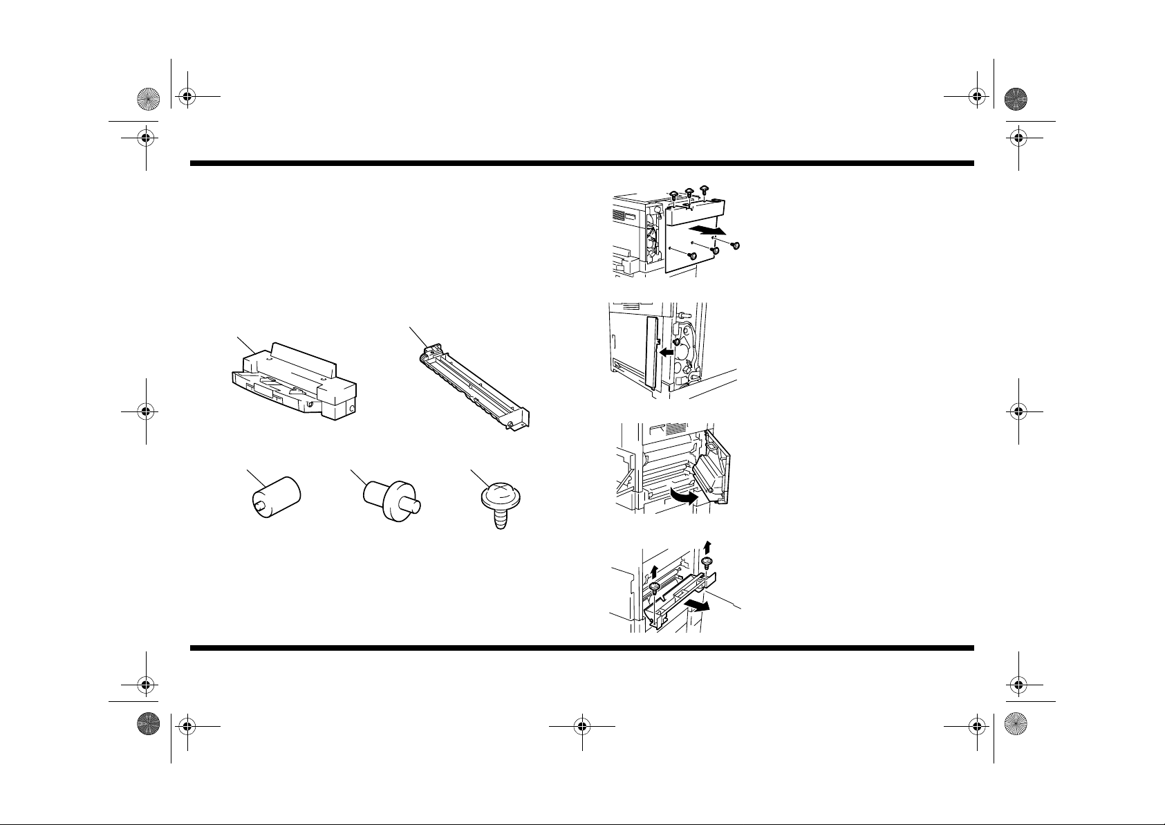
Components
1. Check that the following items are available.
1. Multiple Bypass Tray ............................................................................. 1
2. Guide Plate............................................................................................ 1
3. Positioning Pin................ ...... ..... ............................... ...... ..... ..... ..... ........1
4. Roll ........................................................................................................ 1
5. Screws................................................................................................... 6
1
4687U004AA
3 4 5
2
4021U037AA
MB-5
■
Installation of the Multiple Bypass Tray
4695U001AA
4687U003AA
1. Remove the Rear Cover (6 screws).
2. Loosen one screw and remove the cover
shown.
3. Open the Right Door.
4687U005AA
4687-7744-01
4687U006AA
4687U007AA
4021U004AA
4. Remove the Single Multiple Bypass Tray
Assy (2 screws) and unplug one connectors.
4687U028AA
– 1 –
Page 3

4687-7744-01.fm Page 2 Tuesday, July 31, 2001 4:44 PM
MB-5
4687U027AA
4021U032AA
4021U041AA
5. Remove the harness from the edge cover
and remove the Paper Take-Up Solenoid
(1 screw).
6. Remove the rolls. (4 rolls)
7. Install the Rolls shipped with the Multiple
Bypass Tray. (4 rolls)
8. Remove the cover (2 screws).
9. Temporarily secure the Multiple Bypass Tray.
(4 screws)
4021U033AA
10.Remove the Cover. (1 screw)
4687U013AA
11.Connect the connector of the Mult i Bypass
Tray to the machine. (2 connectors)
4687U008AA
12.Install the Guide Plate shipped with the tray,
trying to push it toward the machine
(2 screws).
4687U014AA
4687-7744-01
4687U031AB
– 2 –
Page 4

4687-7744-01.fm Page 3 Tuesday, July 31, 2001 4:44 PM
MB-5
4687U002AB
4687U012AA
4687U034AA
13.Close the Right Door and secure the harness
of the Multi Bypass Tray using the wiring
saddle fitted to the guide.
NOTE
Secure the harness at the location to the
right of the tie band shown.
14.Reinstall the cover which has been removed
in step 10.
15.Open the Right Door and install the
positioni ng pin at the location shown.
16.Close the Right Door and correctly posi tion
the Multi Bypass Tray using the positioning
pin.
* Check to see if the harness routed in step 13
is too taut.
17.Tighten the four screws of the Multi Bypass
Tray.
18.Remove the positioning pin.
NOTE
Save the positioning pin which has been
removed.
19.Loosen the screw shown and bring the lever
into contact with the jig.
20.Tighten the screws one.
4687U001AD
21.Install the Cover. (2 screws)
* Check that the harness is not wedged in
mechanism.
4687U029AB
4687-7744-01
– 3 –
Page 5

4687-7744-01.fm Page 4 Tuesday, July 31, 2001 4:44 PM
■
CD Registration Adjustment
1. Turn ON the Power Switch.
2. Load the 1st Tray with A4C or LetterC
crosswise paper.
3. Call the Tech. Rep. mode to the screen. (For
the specific procedures to access the Tech.
4688U032AA
Rep. mode, refer to the Service Manu al.)
MB-5
7. Place the test print produced on the Original
Glass.
Paper direction: A4C or LetterC
4687U010AA
Start
4688U032AA 4021U058BA
4688U033AA 4021O109AA
468U009AA
4686U011CA
4687-7744-01
4. Press the Stop key and, immediately, press
the Start key to call the Adjust mode to the
screen.
Stop
5. Enter “12” from the 10-Key Pad.
6. Select the 1st Tray using the Paper key and
press the Start key to let the machine
produce a test print.
4687U011AA
4686U009AA
4687U035AA
– 4 –
8. Place a sheet of paper on the Multi Bypass
Tray.
Paper direction: A4C or LetterC
A
9. Measure dimension (A) on the copy.
Specifications
A4C : 2.0 mm ± 2.0 mm
LetterC: 11.2 mm ± 2.0 mm
10.If dimension (A) falls outside the specified
range, perform the following steps to make
an adjustment.
11.Rotate the fixing screw of the Multi Bypass
Tray and adjust the position of the Multi
Bypass Tray.
12.Make a copy again and c heck th at di mensio n
(A) falls within the specified range.
 Loading...