

Page 1
4689-7744-01.fm Page 0 Tuesday, July 31, 2001 4:45 PM
SETUP INSTRUCTIONS
JS-202
NOTES
•Before setting up, be sure to unplug the power cord of the machine.
•Keep all packing materials out of the reach of children.
4689-7744-01 © MINOLTA CO., LTD. Printed in Japan
Page 2
NOTE
4689-7744-01.fm Page 1 Tuesday, July 31, 2001 4:45 PM
■
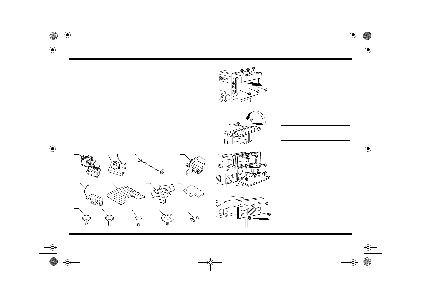
Components
1. Check that the following items are available.
1. PWB Unit...............................................................................................1
2. Motor Unit.. ................................ ..... ..... ...... ..... ............................... ..... ... 1
3. Link Unit................ ..... ..... ...... ............................... ..... ...... ..... ..... ..... ........ 1
4. Sensor Unit............................................................................................ 1
5. Indicator Lamp....................................................................................... 1
6. Tray........................................................................................................ 1
7. Holder.................................................................................................... 1
8. Holder.................................................................................................... 6
9. Tapping Screw 3 x 8 mm (S tight).......................................................... 1
10. Tapping Screw 3 x 8 mm (B tight).......................................................... 1
11. Countersunk flat head screw 3 x 6 mm .................................................1
12. Screw (4163-5293) .................... ..... ..... ...... ..... ............................... ..... ... 1
13. E-ring..................................................................................................... 2
14. Setup Instructions.................................................................................. 1
JS-202
■
Installation of the Job Tray
4695U001AA
4689U026AC
1. Remove the Rear Cover. (6 screws)
2. Remove the screws from the control panel,
and turn over the control panel and place it
on the Original Glass. (2 screws)
Do not remove the harness and ground
wire.
1 2 3
4689U004AB
4689U005AB
5 6
4689U002AA
9
4689U050AA 4689U051AA 4689U042AA 4689U043AA 4689U052AA
4689U001AB
10
4689U007AB
7
11
4689U003AA
12
4
4689U006AC
8
4689U041AA
13
4689-7744-01
3. Open the Front Door and remove the Front
Cover. (6 screws)
4689U027AA
4. Remove the Right Cover. (4 screws)
4689U028AC
– 1 –
Page 3

NOTE
4689-7744-01.fm Page 2 Tuesday, July 31, 2001 4:45 PM
JS-202
4689U023AD
4689U009AB
4689U010AB
arm
5. Remove the screw and pull the Middle Cover
straight out to remove it. (1 screw)
6. Remove the Fan Cover (2 screws) and the
Shifter Stopper Jig (1 screw).
7. Fit the Link Unit to the bushing.
Make sure that the gear at the front of the
•
Link Unit faces as illustrated.
Perform the steps of mounting the Link
•
Unit arm that follow with the Link Unit in
this position.
8. Fit the protrusion of the arm into the hole in
the frame in the rear as illustrated and
secure it using one screw.
Mounting screw: 9739-0308
arm
4689U013AC
upper
lower
4689U045AB
10.Fit the protrusion of the frame at the front into
the hole in the arm as illustrated and secure
it using one screw.
Mounting screw: 4163-5293
Use the round hole, not the oval one, in the
arm to tighten the screw.
11.Insert the bushing of the Link Unit into the
bushing of the machine at the location shown
and snap on t he E-ring.
12.Check that the two paper sensors are at the
correct positions as illustrated.
Make sure that they are in the right positions,
not in reverse, as they are installed.
4689U044AB
4689-7744-01
9. Fit the bushing of the Link Unit into the
bushing of the machine as illustrated. Then,
snap on the E-ring.
– 2 –
Page 4

NOTE
NOTE
4689-7744-01.fm Page 3 Tuesday, July 31, 2001 4:45 PM
JS-202
4689U015AA
4689U022AA
4689U054AA
cord
clamp
13.Remove the harness of the machin e from the
cord clamp and position it on the front so that
it is not placed under the PWB Unit.
14.Install the PWB Unit, while routing the
harness of the PWB Unit along the space
behind the fan.
Mounting screw: 9735-0608
NOTE
Tighten the screws starting first with the left
one.
15.Connect the harness of the machine to the
connector (PJ1) of the PWB Unit and hook
the harness in the cord clamp.
16.Remove the Counter Unit if the machine is
so equipped.
NOTE
Be sure to unplug the connector. If the
connector is left plugged in, the harness
could be damaged by the edge of the
reinforcement plate, becoming opencircuited.
4689U049AB
➀
4689U020AA
4689U021AC
edge
cover
guide
17.Route the harness by securing it with the
guide as illustrated.
18.Install the Motor Unit so that the connector is
➂
on the upper side. (3 screws)
Mounting screw: 9735-0608
Tighten the screws in numerical order
➁
indicated. During the procedure, try to
push the Motor Unit to ensure that there is
no clearance between the Motor Unit and
paper exit frame.
19.Connect the Motor Unit harness to the PWB
Unit harness.
20.Connect the harness extending from the
PWB Unit to the Sensor Unit.
Connect the harness of the blue connector
to the sensor on the front side.
4689-7744-01
– 3 –
4689U018AB
21.Pass the harness, which has been
connected to the sensor on the front side,
into an edge cover.
Page 5

NOTE
4689-7744-01.fm Page 4 Tuesday, July 31, 2001 4:45 PM
JS-202
4689U019AA
4689U008AA
4689U046AC
22.Aligning the tab on the bottom of the Sensor
Unit with the hole for fixing the Shifter, install
the Sensor Unit. (1 screw)
Mounting screw: 9735-0608
23.Cut out the knockouts (at four places) from
the Middle Cover.
24.Tilt the Middle Cover and, keeping that
position, insert it from the front as illustrated.
Then, raise the cover into the upright position
to install it in position. (1 screw)
25.Install the Holder.
26.Fit the Tray to the arms at two places of the
Lint Unit as illustrated.
4689U024AB
27.Install the holder. (1 countersunk flat head
screw)
Mounting screw: 9657-0306
4689U030AB
28.Install the Fan Cover. (2 screws)
4689U036AA
29.Install the Indicator Lamp to the Front Cover.
Before installing the Indicator Lamp, pass
the harness of the Indicator Lamp through
the hole in the Front Cover.
4689U029AA
4689-7744-01
4689U025AA
– 4 –
Page 6

4689-7744-01.fm Page 5 Tuesday, July 31, 2001 4:45 PM
JS-202
4689U039AB
4689U047AB
4689U055AB
30.Install the Front Cover. (6 screws)
NOTE
Make sure that the flat cable of the control
panel is placed on top of the Front Cover.
The flat cable can be damaged if left
drooped.
31.Correctly position the Front Cover. Then,
connect the Indicator Lamp harness to the
PWB Unit harness.
NOTES
•
Pass the edge cover of the Motor Unit.
•
Pull the harness to prevent it from interfering with the motor teeth.
32.If the steps have been performed with the
Counter Unit removed, plug in the connector
and reinstall the Counter Unit back again.
33.Install the Right Cover. (4 screws)
34.Install the control panel. (2 screws)
4689U048AB
35.Install the Rear Cover. (6 screws)
4689U038AA
4689U037AB
4689-7744-01
– 5 –
 Loading...