

Page 1
4690-7744-01.fm Page 0 Tuesday, July 31, 2001 4:45 PM
SETUP INSTRUCTIONS
OT-103
NOTES
•Before setting up, be sure to unplug the power cord of the machine.
•Keep all packing materials out of the reach of children.
4690-7744-01 © MINOLTA CO., LTD. Printed in Japan
Page 2
NOTE
4690-7744-01.fm Page 1 Tuesday, July 31, 2001 4:45 PM
■
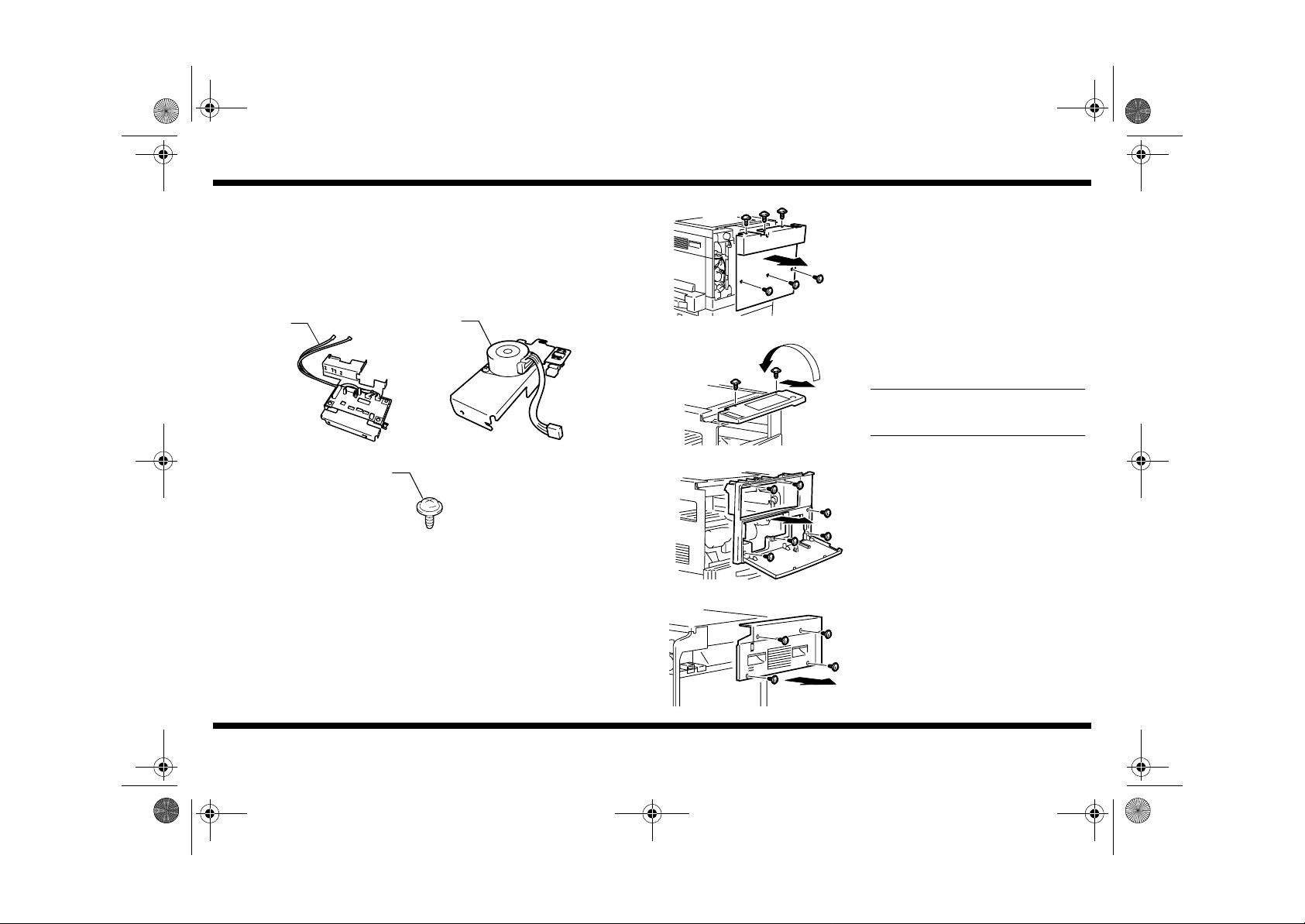
Components
1. Check that the following items are available.
1. PWB Unit............................................................................................... 1
2. Motor Unit.. ...... ..... ..... ................................ ..... ..... ..... ...... ..... ..... ............. 1
3. Tapping Screw 3 x 6 mm ....................................................................... 3
4. Setup Instructions.................................................................................. 1
OT-103
■
Installation of the Shift Tray
1. Remove the Rear Cover. (6 screws)
4690-7744-01
1
4690U004AA
3
4690U010AA
2
4690U005AA
4695U001AA
2. Remove the screws from the control panel,
and turn over the control panel and place it
on the Original Glass. (2 screws)
Do not remove the harness and ground
wire.
4689U026AC
3. Open the Front Door and remove the Front
Cover. (6 screws)
4689U027AA
4. Remove the Right Cover. (4 screws)
4689U028AC
– 1 –
Page 3

NOTES
4690-7744-01.fm Page 2 Tuesday, July 31, 2001 4:45 PM
OT-103
4689U023AD
4689U009AB
4690U001AA
cord
clamp
5. Remove the screw and pull the Middle Cover
straight out to remove it. (1 screw)
6. Remove the Fan Cover (2 screws) and the
Shifter Stopper Jig (1 screw).
7. Install the PWB Unit, while routing the
harness of the PWB Unit along the space
behind the fan.
NOTES
•
Position the harness of the machine on
the front so that it is not placed under the
PWB Unit.
•
Tighten the screws starting first with the
left one. Tighten the screw on the righthand side from the backside.
8. Connect the harness of the machine to the
connector (PJ1) of the PWB Unit and hook
the harness in the cord clamp.
4689U054AA
4692U006AB
4690U009AB
guide
9. Remove the Counter Unit if the machine is
so equipped.
•
Do not unplug the connector.
•
Perform this step with care not to allow
the harness to be damaged by the edge
of the reinforcement plate.
10.Connect the harness extending from the
PWB Unit to the motor harness (4-wire) of
the Motor Unit and to the connector (3- wi re)
of the sensor.
11.Secure the harness to the guide as
illustrated.
12.Install the Motor Unit so that it is properly
doweled into position at the front and rear as
illustrated. (1 screw)
4689U022AA
4690-7744-01
4690U007AC
– 2 –
Page 4

4690-7744-01.fm Page 3 Tuesday, July 31, 2001 4:45 PM
OT-103
4690U011AA
4690U008AC
4689U035AB
13.If the steps have been performed with the
Counter Unit removed, reinstall it back again.
14.Install the Fan Cover. (2 screws)
15.Install the Middle Cover, placing it all the way
straight into the machine.
16.Install the Right Cover. (4 screws)
17.Install the Front Cover. (6 screws)
4690U002AA
18.Install the control panel. (2 screws)
4690U048AB
19.Install the Rear Cover. (6 screws)
4690U038AA
4690U003AC
4690-7744-01
– 3 –
 Loading...