

Page 1
4686-7744-01.fm Page 0 Tuesday, July 31, 2001 4:44 PM
SETUP INSTRUCTIONS
Paper Feeding Cabinet
PF-120
NOTES
•Before setting up, be sure to unplug the power cord of the machine.
•Keep all packing materials out of the reach of children.
4686-7744-01 Printed in Japan
Page 2
4686-7744-01.fm Page 1 Tuesday, July 31, 2001 4:44 PM
■
Components
1. Check that the following items are available.
1. Cover..................................................................................................... 1
2. Size Label.............................................................................................. 1
3. Screw (9742-0412) .................... ..... ................................ ..... ..... ............. 3
4. Screw (9654-0306): May or may not be used ............................... ..... ... 2
5. Screw (9739-0408): May or may not be used ............................... ..... ... 1
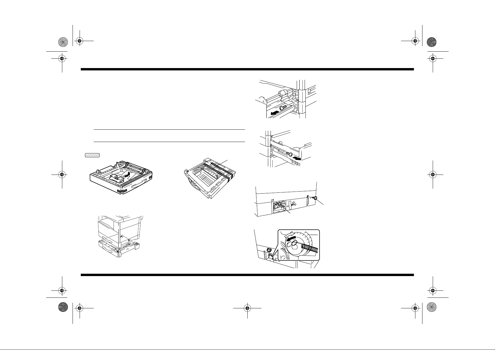
2. Remov e the cushioning materials.
NOTE
Peel off the tape slowly with care not to allow the lever to come off position.
PF-120
2. Slide out the drawer of the machine and the
Paper Feed Unit and secure the Paper Feed
Unit by tightening the two screws at the front.
Mounting Screw: 9742-0412
4686U023AB
Mounting Screw: 9742-0412
Tape
4686U015AA
■
Installation to the Machine
4686U018AB
4686-7744-01
Lever
4686U026AA
1. While confirming the protrusion of the Paper
Feed Unit, mount the machine.
4686U024AB
4686U003AA
4686U005AB
– 1 –
3. Secure the Paper Feed Unit by tightening the
two screws in the rear.
Mounting Screw:
➁
➀
Mounting Screw:
4. Press the portion shown in the direction of
the arrow and then release it to see if it
returns to the original position.
If it does not return, perform steps 5 and 6.
9739-0405
➀
9742-0412
➁
Page 3

4686-7744-01.fm Page 2 Tuesday, July 31, 2001 4:44 PM
5. Remove the Rear Cover (6 screws).
PF-120
■
Installation of One Paper Feed Unit to Another
1. Mount one Paper Feed Unit to another.
4695U001AA
4686U007AA
Red Line
4686U021AB
4686U022AB
4686-7744-01
6. Loosen the screw shown, push the bracket in
the direction of the arrow, and then release it.
When the bracket returns to its original
position, tighten the screw.
screws
7. Remove the tape and plug the connector of
the Paper Feeding Cabinet into the machine.
8. Install the cover. (1 screw)
Mounting Screw: 9654-0306
4686U001AA
4686U012AA
4686U013AA
4686U006AB
– 2 –
2. Slide out the drawer of each Paper Feed Unit
and secure the two Paper Feed Units
together at the front.
Mounting Screw: 9742-0412
Mounting Screw: 9742-0412
3. Secure the Paper Feed Units together in the
rear.
Mounting Screw:
➁
Mounting Screw:
➀
9654-0306
➀
9742-0412
➁
Page 4

NOTE
4686-7744-01.fm Page 3 Tuesday, July 31, 2001 4:44 PM
4. Plug the connector of one Paper Feed Unit
into that of another.
PF-120
■
Loading the Paper Feed Unit with Paper
1. Slide out the drawer of the Paper Feed Unit
and press dow n the Pa per Li fting Plate until it
locks in position.
4686U002AA
4686U022AB
4686-7744-01
5. Reinstall the covers. (1 screw)
Mounting Screw: 9654-0306
4021O042AB
2. Load the paper.
Do not load so much paper that the top of
the stack is higher than the ▼ mark.
4021O043AC
3. Slide the Edge Guide and Trailing Edge Stop
so that they are pressed tightly up against
the edges of the paper stack.
4021O044AB
– 3 –
Page 5

4686-7744-01.fm Page 4 Tuesday, July 31, 2001 4:44 PM
■
Paper Passage Check
1. Turn ON the machine.
2. Press the Paper key to select the 2nd Tray.
PF-120
■
CD Registration Adjustment
1. Call the Service mode to the Display. (For
the procedure to call the Service mode to the
Display, see the Service Manual.)
4686U011CA
4686U010CA
4686-7744-01
3. Press the Start key to check for correct
paper passage.
If the paper is not properly fed, perform steps
5, 6, and 7 on pp. 1 to 2 once again.
4688U032AA
2. Press the Stop key and then immediat ely
press the Start key to call the Adjust mode to
the Display.
4688U032AA 4686U010CA
3. Using the 10-Key Pad, enter “12.”
4688U033AA 4021O109AA
4. Select the drawer to be adjusted using the
Paper key, then press the Start key to let the
machine produce a test print.
4688U008AA 4686U110CA
– 4 –
Page 6

4686-7744-01.fm Page 5 Tuesday, July 31, 2001 4:44 PM
A
5. Measure dimension (A) of the test print.
Specifications
A4C : 20 ± 2.0 mm
LetterC: 11.2 ± 2.0 mm
6. If dimension (A) falls outside the specified
4686U009AA
range, perform the following adjustment
procedure.
7. Slide out the 2nd Tray and loosen the screw
shown.
4686U025AB
If dimension A is more than the specified range,
move the Edge Guide in the direction of the
arrow.
PF-120
■
Affixing the Size Label
4686U014AA
Affix the Size Label to the Paper Feeding Cabinet.
4686U068AA
4686U067AA
4686-7744-01
If dimension A is less than the specified range,
move the Edge Guide in the direction of the
arrow.
8. After the adjustment has been made,
produce a test print again and make a check
again.
– 5 –
 Loading...