

Page 1
4021-7744-01.fm Page 0 Tuesday, July 31, 2001 4:43 PM
SETUP INSTRUCTIONS
Di152/Di183
NOTES
•Before setting up, be sure to unplug the power cord of the machine.
•Keep all packing materials out of the reach of children.
4021-7744-01 © MINOLTA CO., LTD. Printed in Japan
Page 2
4021-7744-01.fm Page 1 Tuesday, July 31, 2001 4:43 PM
■
Components
1. Check that the following items are available.
1. User Manual .............. ..... ................................ ..... ..... ...... ....................... 1
2. Warranty Card (U.S.A. and Canada only) ............................................. 1
3. Manual Holder ....................................................................................... 1
4. Power Cord............................................................................................ 1
5. Size Label.............................................................................................. 1
6. Seal ....................................................................................................... 1
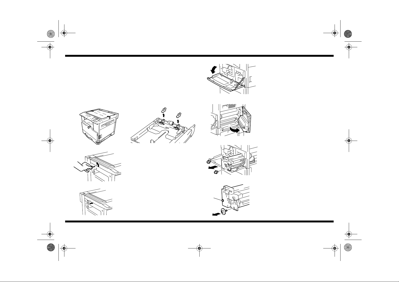
2. Remove tape.
4021U039AA 1171U013AA
3. Remove the Scanner Fixing Pin.
Di152/Di183
4021U003AA
■
Loading the Starter
4021U004AA
5. Open the Front Door.
1. Open the Right Door.
2. Remove two screws and the Imaging Unit.
4021U026AA
4021U083AA
4021-7744-01
4. Affix the Seal (accessory) in the position as
show.
4021U005AB
4021U012AB
– 1 –
3. Remove one screw at the location shown
from the front side of the Imaging Unit.
➀
Loosen screw ➀.
Page 3

NOTE
NOTE
4021-7744-01.fm Page 2 Tuesday, July 31, 2001 4:43 PM
4. Remove two screws at the location shown
from the rear side of the Imaging Unit.
Loosen screw ➁.
➁
Di152/Di183
Before reinstalling the Imaging Unit, be
sure to place the connector and harness
into the slit properly.
4021U011AB
4021U007AC
4021U006AB
4021U040AA
4021-7744-01
5. Opening both ends of the Cleaning Assy,
swing it down toward the rear as illustrated.
6. Remove the cover. (3 screws)
NOTE
The center screw is different from the
others.
7. Load the Imaging Unit with a packet of
starter.
NOTE
Before pouring the starter, shake the
packet well.
8. Reinstall the cover.
4021U066AA
4021U042AB
■
ATDC Sensor Adjustment
4688U032AA
– 2 –
9. Reinstall the parts which have been removed
and slide the Imaging Unit back into the
machine.
When reinstalling the Imagi ng Unit, sl owly
push it until you feel that the drum gear is
blocked and then slide it all the way toward
the rear. Doing these steps all at once
could damage the drum gear.
10.Close the Front Door.
1. Turn ON the Power Switch.
2. Call the Tech. Rep. Mode to the screen. (For
the procedure to access Tech. Rep. Mode,
see the Service Manual.)
Page 4

4021-7744-01.fm Page 3 Tuesday, July 31, 2001 4:43 PM
3. Enter “1” from the 10-Key Pad to call the
Function mode to the screen.
Di152/Di183
■
Installing the Manual Holder
Mount the Manual Holder as shown .
4688U032AA 4021O109AA
4021U053AA 4021O109AA
Start
4021U054AA 4021U058BA
4021U055AA 4021U013AA
4021-7744-01
4. Enter “8” from the 10-Key Pad.
5. Press the Start key. (This automatically
starts the ATDC Sensor adjustment
procedure.)
Stop
6. After the ATDC Sensor adjustment
procedure has been completed, open the
Front Door and enter the ATDC level setting
value displayed on the screen in the Adjust
Label.
4021U069AA
■
Installing the Toner Bottle
1166O228AA
1166O095AA
1139O139OA
– 3 –
1. Sharply tap the new Toner Bottle against a
desk or other hard surface four to five times.
Then, turn the Toner Bottle upside down and
tap it the same way again. (Be sure to carry
out this procedure, as toner can be caked in
the bottle.)
2. Shake the new Toner Bottle well and turn it
upside down five times.
3. With the seal on the Toner Bottle facing up,
slowly peel off the seal as illustrated.
Page 5

NOTE
4021-7744-01.fm Page 4 Tuesday, July 31, 2001 4:43 PM
Di152/Di183
4021U014AA
4021U015AA
■
Loading Paper
4021O037AB
4. Open the Front Door.
5. Swing open the Bottle Holder to the front and
position the Toner Bottle.
NOTE
Make sure that the UP marking faces up.
6. Close the Bottle Holder and the Front Door.
1. Slide out the 1st Tray.
2. Press down on the Paper Lifting Plate.
3. Load the paper in the tray.
4021O039AB
4. Slide the Edge Guide and Trailing Edge Stop
5. Slide the tray back into the machine.
4021O200AB
■
Affixing the Panel Sh e e t a nd Size Label
1. Affix the panel sheet to the panel of the
4021U059AA
2. Affix the size label to the 1st Tray.
Do not load so much paper that the top of
the stack is higher than the mark.
against the edges of the paper stack.
<Europe only>
machine.
4021O038AB
4021-7744-01
4021U056AA
– 4 –
Page 6

4021-7744-01.fm Page 5 Tuesday, July 31, 2001 4:43 PM
■
Mounting the Original Cover (Option)
4021U060AA
Install the Original Cover.
Di152/Di183
4021-7744-01
– 5 –
 Loading...