

Page 1
Service Manual
[Field Service]
Di152/Di183
Page 2

FrameMaker Ver.5.5(PC) Di152/Di183
01.08.06
INDEX (FIELD SERVICE)
SAFETY PRECA UTIONS FOR
INSPECTION AND SERVICE
DIS/REASSEMBLY,
ADJUSTMENT
SWITCHES ON PWBs,
TECH. REP. SETTINGS
TROUBLESHOOTING
Page 3
FrameMaker Ver.5.5E(PC) PL/PS Standard Document Ver.03
01.04.23
1. SAFETY PRECAUTIONS FOR INSPECTION AND SERVICE
• When performing inspection and service procedures, observe the following precautions
to prevent accidents and ensure utmost safety.
✽
Depending on the model, some of the precautions given in the following do not apply.
• Different markings are used to denote specific meanings as detailed below.
Indicates a potentially hazardous situation which, if not avoided,
WARNING
CAUTION
• The following graphic symbols are used to give instructions that need to be observed.
Used to call the service technician’s attention to what is graphically represented
inside the marking (including a warning).
Used to prohibit the service technician’s from doing what is graphically represented inside the marking.
could result in death or serious injury.
Indicates a potentially hazardous situation which, if not avoided,
may result in minor or moderate injury. It may also be used to
alert against unsafe practices.
Used to instruct the service technician’s to do what is graphically represented
inside the marking.
1-1. Warning
WARNING
1. Always observe precautions.
• Parts requiring special attention in this product will include a label containing the
mark shown on the left plus precautionary notes. Be sure to observe the precautions.
• Be sure to observe the “Safety Information” given in the O perator’s Manual.
2. Before starting the procedures, be sure to unplug the power cord.
• This product contains a high-voltage unit and a circuit with a large current
capacity that may cause an electric shock or burn.
• The product also contains parts that can jerk suddenly and cause injury.
• If this product uses a laser, laser beam leakage may cause eye damage or
blindness.
P-1
Page 4

FrameMaker Ver.5.5E(PC) PL/PS Standard Document Ver.03
01.04.23
3. Do not throw toner or the toner bottle into a fir.
• Do not throw toner or the toner bottle (Imaging Cartridge) into a fire. Toner
expelled from the fire may cause burns.
4. Use the specified parts.
• For replacement parts, always use the genuine parts specified in the manufacturer’s parts manual. Installing a wrong or unauthorized part could cause dielectric breakdown, overload, or undermine safety devices resulting in possible
electric shock or fire.
• Replace a blown electrical fuse or thermal fuse with its corresponding genuine
part specified in the manufacturer’s parts manual. Installing a fuse of a different
make or rating could lead to a possible fire. If a thermal fuse blows frequently,
the temperature control system may have a problem and action must be taken
to eliminate the cause of the problem.
5. Handle the power cord with care and never use a multiple outlet.
• Do not break, crush or otherwise damage the power cord. Placing a heavy
object on the power cord, or pulling or bending it may damage it, resulting in a
possible fire or electric shock.
• Do not use a multiple outlet to which any other appliance or machine is connected.
• Be sure the power outlet meets or exceeds the specified capacity.
6. Be careful with the high-voltage parts.
• A part marked with the symbol shown on the left carries a high voltage. Touching it could result in an electric shock or burn. Be sure to unplug the power cord
before servicing this part or the parts near it.
7. Do not work with wet hands.
• Do not unplug or plug in the power cord, or perform any kind of service or
inspection with wet hands. Doing so could result in an electric shock.
8. Do not touch a high-temperature part.
• A part marked with the symbol shown on the left and other parts such as the
exposure lamp and fusing roller can be very hot while the machine is energized.
Touching them may result in a burn.
• Wait until these parts have c ooled down before replacing them or any surrounding parts.
9. Maintain a grounded connection at all times. (This item may not apply in the USA.)
• Be sure to connect the ground wire to the ground terminal even when performing an inspection or repair. Without proper grounding, electrical leakage could
result in an electric shock or fire.
• Never connect the ground wire to a gas pipe, water pipe, telephone ground wire,
or a lightning conductor.
10. Do not remodel the product.
• Modifying this product in a manner not authorized by the manufacturer may
result in a fire or electric shock. If this product uses a laser, laser beam leakage
may cause eye damage or blindness.
P-2
Page 5
FrameMaker Ver.5.5E(PC) PL/PS Standard Document Ver.03
01.04.23
11. Restore all parts and harnesses to their original positions.
• To promote safety and prevent product damage, make sure the harnes ses are
returned to their original positions and properly secured in their clamps and saddles in order to avoid hot parts, high-voltage parts, sharp edges, or being
crushed.
• To promote safety, make sure that all tubing and other insulating materials are
returned to their original positions. Make sure that floating components mounted
on the circuit boards are at their correct distance and position off the boards.
1-2. Caution
CAUTION
1. Precautions for Service Jobs.
• A toothed washer and spring washer, if used or iginally, must be reinstalled.
Omitting them may result in contact failure wh ich could cause an electric shock
or fire.
• When reassembling parts, make sure that the correct screws (size, type) are
used in the correct places. Using the wrong screw could lead to stripped
threads, poorly secured parts, poor insulating or grounding, and result in a malfunction, electric shock or injury.
• Take great care to avoid personal injury from possible burrs and sharp edges on
the parts, frames and chassis of the product.
• When moving the product or removing an option, use care not to injure your
back or allow your hands to be caught in mechanisms.
2. Precautions for Servicing with Covers and Parts Removed.
• Wherever feasible, keep all parts and covers mounted when energizing the
product.
• If energizing the product with a cover removed is absolutely unavoidable , do not
touch any exposed live parts and use care not to allow your clothing to be
caught in the moving parts. Never leave a product in this condition unattended.
• Never place disassembled parts or a container of liquid on the product. Parts
falling into, or the liquid spilling inside, the mechanism could result in an electric
shock or fire.
• Never use a flammable spray near the product. This could result in a fire.
• Make sure the power cord is unplugged before removing or installing circuit
boards or plugging in or unplugging connectors.
• Always use the interlock switch actuating jig to actuate an interlock switch when
a cover is opened or remove d. The use of folded paper or some other object
may damage the interlock switc h mechanism, poss ibly resulting in an electric
shock, injury or blindness.
P-3
Page 6

FrameMaker Ver.5.5E(PC) PL/PS Standard Document Ver.03
01.04.23
3. Precautions for the Working Environment.
• The product must be placed on a flat, level surface that is stable and secure.
• Never place this product or its parts on an unsteady or tilting workbench when
servicing.
• Provide good ventilation at regular intervals if a s ervice job must be done in a
confined space for a long period of time.
• Avoid dusty locations and places exposed to oil or steam.
• Avoid working positions that may block the ventilation ports of the product.
4. Precautions for Handling Batteries. (Lithium, Nickel-Cadmium, etc.)
• Replace a rundown battery with the same type as specified in the manufacturer’s parts manual.
• Before installing a new battery, make sure of the correct polarity of the installation or the battery could burst.
• Dispose of used batteries according to the local regulations. Never dispose of
them at the user’s premises or attempt to try to discharge one.
5. Precautions for the Laser Beam. (Only for Products Employing a Laser)
• Removing the cover marked with the caution label could lead to possible exposure to the laser beam, resulting in eye damage or blindness. Be sure to unplug
the power cord before removing this cover.
• If removing this cover while the power is ON is unavoidab le , be sure to wear protective laser goggles that meet specifications.
• Make sure that no one enters the room when the machine is in this condition.
• When handling the laser unit, observe the “Precautions for Handling Laser
Equipment.”
6. Precautions for storage the toner or imaging cartridge.
• Be sure to keep the toner or imaging cartridge out of the reach of children. Licking the imaging cartridge or ingesting its contents is harmful to your health.
1-3. Other Precautions
• When handling circuit boards, observe the “HANDLING of PWBs”.
• The PC Drum is a very delicate component. Observe the precautions given in “HANDLING OF THE PC DRUM” because mishandling may result in serious image problems.
• Note that replacement of a circuit board may call for readjustments or resetting of particular items, or software installation.
P-4
Page 7

FrameMaker Ver.5.5E(PC) PL/PS Standard Document Ver.03
01.04.23
1-4. Used Batteries Precautions
ALL Areas
Danger of explosion if battery is incorrectly replaced.
Replace only with the same or equivalent type recommended by the manufacturer.
Dispose of used batteries according to the manufacturer’s instructions.
Germany
Explosionsgefahr bei unsachgemäßem Austausch der Batterie.
Ersatz nur durch denselben oder einen vom Hersteller empfohlenen gleichwertigen Typ.
Entsorgung gebrauchter Batterien nach Angaben des Herstellers.
France
Il y a danger d’explosion s’il y a remplacement incorrect de la batterie.
Remplacer uniquement avec une batterie du même type ou d’un type équivalent recommandé par le constructeur.
Mettre au rebut les batteries usagées conformément aux instructions du fabricant.
Denmark
Lithiumbatteri - Eksplosionsfare ved fejlagtig håndtering.
Udskiftning må kun ske med batteri af samme fabrikat og type.
Levér det brugte batteri tilbage til leverandøren.
Finland, Sweden
Paristo voi räjähtää, jos se on virheellisesti asennettu.
Vaihda paristo ainoastaan laitevalmistajan suosittelemaan tyyppiin.
Hävitä käytetty paristo valmistajan ohjeiden mukaisesti.
CAUTION
VORSICHT!
ATTENTION
ADVARSEL!
VAROlTUS
VARNING
Explosionsfara vid felaktigt batteribyte.
Använd samma batterityp eller en ekvivalent typ som rekommenderas av apparattillverkaren.
Kassera använt batteri enligt fabrikantens instruktion.
Norway
Eksplosjonsfare ved feilaktig skifte av batteri.
Benytt samme batteritype eller en tilsvarende type anbefalt av apparatfabrikanten.
Brukte batterier kasseres i henhold til fabrikantens instruksjoner.
ADVARSEL
P-5
Page 8

FrameMaker Ver.5.5E(PC) PL/PS Standard Document Ver.03
01.04.23
1-5. Precautions for Service
• When performing inspection and service procedures, observe the following precautions
to prevent mishandling of the machine and its parts.
✽
Depending on the model, some of the precautions given in the following do not apply.
1. Precautions Before Service
• When the user is using a word processor or personal computer from a wall outlet of the
same line, take necessary steps to prevent the circuit breaker from opening due to overloads.
• Never disturb the LAN by breaking or making a network connection, altering termination,
installing or removing networking hardware or software, or shutting down networked
devices without the knowledge and express permission of the network administrator or
the shop supervisor.
2. How to Use this Book
< DIS/REASSEMB LY, ADJUSTMENT >
• To reassemble the product, reverse the order of disassembly unless otherwise specified.
< TROUBLESHOOTING >
• If a component on a PWB or any other functional unit including a motor is defective, the
text only instructs you to replace the whole PWB or functional unit and does not give troubleshooting procedures applicable within the defective unit.
• All troubleshooting procedures contained herein assume that there are no breaks in the
harnesses and cords and all connectors are plugged into the right positions.
• The procedures preclude possible malfunctions due to noise and other external causes.
3. Precautions for Service
• Check the area surrounding the service site for any signs of damage, wear or need of
repair.
• Keep all disassembled parts in good order and keep tools under control so that none will
be lost or damaged.
• After completing a service job, perform a safety check. Make sure that all parts, wiring
and screws are returned to their original positions.
• Do not pull out the toner hopper while the toner bottle is turning. This could result in a
damaged motor or locking mechanism.
• If the product is to be run with the front door open, make sure that the toner hopper is in
the locked position.
• Do not use an air gun or vacuum cleaner for cleaning the ATDC Sensor and other sen-
sors, as they can cause electrostatic destruction. Use a blower brush and cloth. If a unit
containing these sensors is to be cleaned, first remove the sensors from the unit.
P-6
Page 9

FrameMaker Ver.5.5E(PC) PL/PS Standard Document Ver.03
01.04.23
4. Precautions for Dis/Reassembly
• Be sure to unplug the copier from the outlet before attempting to service the copier.
• The basic rule is not to operate the copier anytime during disassembly. If it is absolutely
necessary to run the copier with its covers removed, use care not to allow y our clothing to
be caught in revolving parts such as the timing belt and gears.
• Before attempting to replace parts and unplug connectors, make sure that the power
cord of the copier has been unplugged from the wall outlet.
• Be sure to use the Interlock Switch Actuating Jig whenever it is necessary to actuate the
Interlock Switch with the covers left open or removed.
• While the product is energized, do not unplug or plug connectors into the circuit boards
or harnesses.
• Never use flammable sprays near the copier .
• A used battery should be disposed of according to the local regulations and never be dis-
carded casually or left unattended at the user’s premises.
• When reassembling parts, make sure that the correct screws (size, type) and toothed
washer are used in the correct places.
5. Precautions for Circuit Inspection
• Never create a closed circuit across connector pins except those specified in the text and
on the printed circuit.
• When creating a closed circuit and measuring a voltage across connector pins specified
in the text, be sure to use the GND wire.
P-7
Page 10

FrameMaker Ver.5.5E(PC) PL/PS Standard Document Ver.03
01.04.23
6. Handling of PWBs
< During Transportation/St orage >
• During transportation or when in storage, new P.W. Boards must not be indiscriminately
removed from their protective conductive bags.
• Do not store or place P.W. Boards in a location exposed to direct sunlight and high tem-
perature.
• When it becomes absolutely necessary to remove a Board from its conductive bag or
case, always place it on its conductive mat in an area as free as possible from static electricity.
• Do not touch the pins of the ICs with your bare hands.
• Protect the PWBs from any external force so that they are not bent or damaged.
< During Inspection/Replacement >
• Avoid checking the IC directly with a multimeter; use connectors on the Board.
• Never create a closed circuit across IC pins with a m etal tool.
• Before unplugging connectors from the P.W . Boards, make sure that the power cord has
been unplugged from the outlet.
• When removing a Board from its conductive bag or conductive case, do not touch the
pins of the ICs or the printed pattern. Place it in position by holding only the edges of the
Board.
• When touching the PWB, wear a wrist strap and connect its cord to a securely grounded
place whenever possible. If you cannot wear a wrist strap, touch a metal part to discharge static electricity before touching the PWB.
• Note that replacement of a PWB may call for readjustments or resetting of particular
items.
7. Handling of Other Parts
• The magnet roller generates a strong magnetic field. Do not bring it near a watch, floppy
disk, magnetic card, or CRT tube.
P-8
Page 11
FrameMaker Ver.5.5E(PC) PL/PS Standard Document Ver.03
01.04.23
8. Handling of the PC Drum
✽
Only for Products Not Employing an Imaging Cartridge.
< During Transportation/St orage >
• Use the specified carton whenever moving or storing the PC Drum.
• The storage temperature is in the range between –20°C and +40°C.
• In summer, avoid leaving the PC Drum in a car for a long time.
< Handling >
• Ensure that the correct PC Drum is used.
• Whenever the PC Drum has been removed from the copier , store it in i ts carton or protect
it with a Drum Cloth.
• The PC Drum exhibits greatest light fatigue after being exposed to strong light over an
extended period of time. Never, therefore, expose it to direct sunlight.
• Use care not to contaminate the surface of the PC Drum with oil-base solvent, finger-
prints, and other foreign matter.
• Do not scratch the surface of the PC Drum.
• Do not apply chemicals to the surface of the PC Drum.
• Do not attempt to wipe clean the surface of the PC Drum.
If, however, the surface is contaminated with fingerprints, clean it using the following proce-
dure.
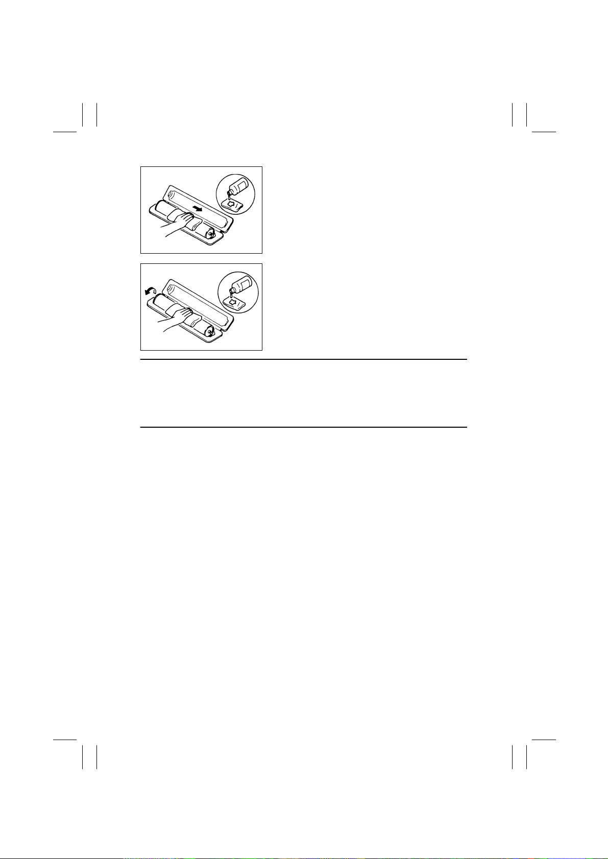
A. Place the PC Drum into one half of its carton.
1076D001
1076D002
B. Gently wipe the residual toner off the surface of the
PC Drum with a dry, Dust-Free Cotton Pad.
• Turn the PC Drum so that the area of its surface on
which the line of toner left by the Cleaning Blade is
present is facing straight up. Wipe the surface in one
continuous movement from the rear edge of the PC
Drum to the front edge and off the surface of the PC
Drum.
• Turn the PC Drum slightly and wipe the newly
exposed surface area with a CLEAN face of the
Dust-Free Cotton Pad. Repeat this procedure until
the entire surface of the PC Drum has been thoroughly cleaned.
✽
At this time, always use a CLEAN face of the dry
Dust-Free Cotton Pad until no toner is e vident on the
face of the Pad after wiping.
P-9
Page 12
FrameMaker Ver.5.5E(PC) PL/PS Standard Document Ver.03
01.04.23
C. Soak a small amount of either ethyl alcohol or iso-
propyl alcohol into a clean, unused Dust-Free Cotton Pad which has been folded over into quarters.
Now, wipe the surface of the PC Drum in one continuous movement from its rear edge to its front
edge and off its surface one to two t imes.
✽
Never move the Pad back and forth.
1076D003
D. Using the SAME face of the Pad, repeat the proce-
dure explained in the latter half of step 3 until the
entire surface of the PC Drum has been wiped.
Always OVERLA P the areas when wiping. Two
complete turns of the PC Drum would be appropriate for cleaning.
1076D004
NOTES
• Even when the PC Drum is only locally dirtied, wipe the entire surface.
• Do not expose the PC Drum to direct sunlight. Clean it as quickly as possible even under
interior illumination.
• If dirt remains after cleaning, repeat the entire procedure from the beginning one more
time.
9. Handling of the Imaging Cartridge
✽
Only for Products Employing an Imaging Cartridge.
< During Transportation/St orage >
• The storage temperature is in the range between –20°C and +40°C.
• In summer, avoid leaving the Imaging Cartridge in a car for a long time.
< Handling >
• Store the Imaging Cartridge in a place that is not exposed to direct sunlight.
< Precautionary Information on the PC Drum Inside the Imaging Cartr idge >
• Use care not to contaminate the surface of the PC Drum with oil-base solvent, fingerprints, and other foreign matter.
• Do not scratch the surface of the PC Drum.
• Do not attempt to wipe clean the surface of the PC Drum.
P-10
Page 13

FrameMaker Ver5.5E(PC) Di152/Di183 DIS/REASSEMBLY, ADJUSTMENT
01.09.03
DIS/REASSEMBLY,
ADJUSTMENT
10230
Page 14

FrameMaker Ver5.5E(PC) Di152/Di183 DIS/REASSEMBLY, ADJUSTMENT
01.09.03
CONTENTS
1. SAFETY INFORMATION ............. ................................................ ....................D-1
1-1. LASER SAFETY ............................................................ ..........................D-1
1-2. INTERNAL LASER RADIATION ..............................................................D-1
1-3. LASER SAFETY LABEL ................. ................................................ .........D-4
1-4. LASER CAUTION LABEL .................................... ......................... ...........D-4
1-5. PRECAUTIONS FOR HANDLING THE LASER EQUIPMENT ...............D-4
2. SERVICE INSTRUCTIONS .............................................................................D-5
2-1. IDENTIFICATION OF FUSES AND CIRCUIT BREAKERS ............. .......D-5
2-2. PARTS WHICH MUST NOT BE TOUCHED .................................... .......D-6
(1) Red Painted Screws ...................................... ..................................D-6
(2) Variable Resistors on Board ................................................... .........D-6
3. DISASSEMBLY/REASSEMBLY ...................................................................... D-7
3-1. DOORS, COVERS, AND EXTERIOR PARTS: IDENTIFICATION
AND REMOVAL PROCEDURES ............................................................D-7
3-2. REMOVAL OF CIRCUIT BOARDS AND OTHER ELECTRICAL
COMPONENTS .......................................................................................D-9
(1) Removal of the Master Board ..........................................................D-10
(2) Removal of the Control Board .........................................................D-11
(3) Removal of the High Voltage Unit ...................................................D-11
(4) Removal of the DC Power Supply . ..................................................D-13
3-3. MAINTENANCE SCHEDULE .................................................................. D-16
3-4. PAPER TAKE-UP/TRANSPORT SECTION ............................................D-18
(1) Removal of the Paper Separator Roll Assy and
Paper Take-Up Roll .........................................................................D-18
(2) Cleaning of the Paper Separator Roll ..............................................D-18
(3) Cleaning of the Paper Take-Up Roll ................................................D-18
(4) Cleaning of the Right and Left Synchronizing Rollers .....................D-19
(5) Removal of the Paper Dust Remover Assy .....................................D-19
(6) Cleaning of the Paper Dust Remover ..............................................D-20
(7) Cleaning of the Bypass Transport Roller .........................................D-20
3-5. OPTICAL SECTION ...................................................... ..........................D-21
(1) Cleaning of the Original Glass and ADF Glass ...............................D-21
(2) Cleaning of Mirrors ..........................................................................D-21
(3) Cleaning of the Lens ...................................................... ....... .. .. .... .. .D-21
(4) Cleaning of the CCD Sensor ...........................................................D-22
(5) Cleaning of the Scanner Rails/Bushings .........................................D-22
(6) Removal of the CCD Unit ................................................................D-23
(7) Removal of the Scanner, Exposure Lamp, and Inverter Board .......D-23
(8) Removal of the Scanner Drive Cables ............................................D-25
(9) Winding of the Scanner Drive Cables ..............................................D-27
3-6. PH ............................................................................................................ D-29
(1) Removal of the PH Unit ...................................................................D-29
(2) Cleaning of the PH Window .............................................................D-29
3-7. Imaging Unit (IU) ......................................................................................D-30
(1) Removal of the IU ............................................................................D-30
(2) Disassembly of the IU ......................................................................D-30
i
Page 15

FrameMaker Ver5.5E(PC) Di152/Di183 DIS/REASSEMBLY, ADJUSTMENT
01.09.03
(3) Application of Toner .........................................................................D-34
(4) Replacement of the ATDC Sensor ..................................................D-35
3-8. IMAGE TRANSFER SECTION ................................................................D-36
(1) Removal of the Image Transfer Roller Assy ....................................D-36
(2) Cleaning of the Pre-Image Transfer Lower Guide Plate ..................D-36
(3) Cleaning of the Charge Neutralizing Pla te ............ ......................... .D-36
3-9. FUSING SECTION ..................................................................................D-37
(1) Removal of the Fusing Unit .............................................................D-37
(2) Disassembly of the Fusing Unit ....................................................... D-37
3-10.MULTIPLE BYPASS (MB-5): OPTION ....................................................D-42
(1) Removal of the Separator Roll Assy ................................................D-42
(2) Removal of the Paper Take-Up Roll ................................................D-42
(3) Cleaning of the Separator Roll/Paper Take-Up Roll ........................D-45
(4) Cleaning of the Paper Take-Up Roll ................................................D-45
3-11.JOB TRAY (JS-202): OPTION ................................................................D-46
(1) Removal of the Main Board .............................................................D-46
(2) Paper Detecting Board .................................................................... D-48
3-12.SHIFTING UNIT (OT-103): OPTION ....................................................... D -49
(1) Removal of the Main Board .............................................................D-49
4. ADJUSTMENT .................................................................................................D-51
4-1. ADJUSTMENT JIGS AND TOOLS USED ...............................................D-51
4-2. TIMING BELT TENSION ADJUSTMENT ............................................. ...D-51
4-3. ACCESSING THE FUNCTION, TECH. REP. CHOICE, AND
ADJUST MODE ...................................... ................................................ .D-52
(1) Function Mode .................................................................................D-52
(2) Tech. Rep. Choice Mode .................................................................D-52
(3) Adjust Mode .......................................................................... .... .... ...D-52
4-4. ELECTRICAL/IMAGE ADJUSTMENT ..................... ................................D-53
(1) Edge Erase Adjustment (Leading, Trailing, and Top/Bottom
Edges) .............................................................................................D-53
(2) Loop Length Adjustment (1st and 2nd Trays, Bypass Tray) ...........D-54
(3) Printer CD Registration Adjustment .................................................D-55
(4) Printer FD Registration Adjustment .................................................D-56
(5) Scanner CD Registration Adjustment ..............................................D-57
(6) Scanner FD Registration Adjustment ..............................................D-58
(7) Scanner CD Zoom Adjustment ........................................................D-59
(8) Scanner FD Zoom Adjustment ...................................... ........... .... ...D-60
(9) ATDC Sensor Automatic Adjustment (F8) .......................................D-61
(10) Manual Bypass Registration Adjustment .... .....................................D-62
(11) Multiple By pa ss Registrati o n Ad j u stment (MB-5) : O p ti o n ........ .. ......D-6 3
4-5. OTHER ADJUSTMENTS ....................................................... ..................D-64
(1) Adjustment of the Position of the Scanner and
2nd/3rd Mirrors Carriage .................................................................D-64
(2) CCD Unit Position Adjustment .......... ......................... ......................D-65
(3) Adjustment of the Gap between the Doctor Blade and
Sleeve Roller (Db Adjustment) ........................................................D-66
4-6. MISCELLANEOUS .................................................................................. D-68
ii
Page 16

FrameMaker Ver5.5E(PC) Di152/Di183 DIS/REASSEMBLY, ADJUSTMENT
01.09.03
(1) Remounting the EEPROM (U29) .....................................................D-68
(2) Installation of the Plug-In Counter Socket (Option) .........................D-69
(3) Installation of the Mechanical Counter (Option) ..............................D-70
iii
Page 17
FrameMaker Ver.5.5E(PC) DIS/REASSEMBLY, ADJUSTMENT FOR Di152/Di183
01.09.03
1. SAFETY INFORMATION
1-1. LASER SAFETY
• This is a digital machine certified as a class 1 laser product. There is no possibility of
danger from a laser, provided the machine is serviced according to the instruction in this
manual.
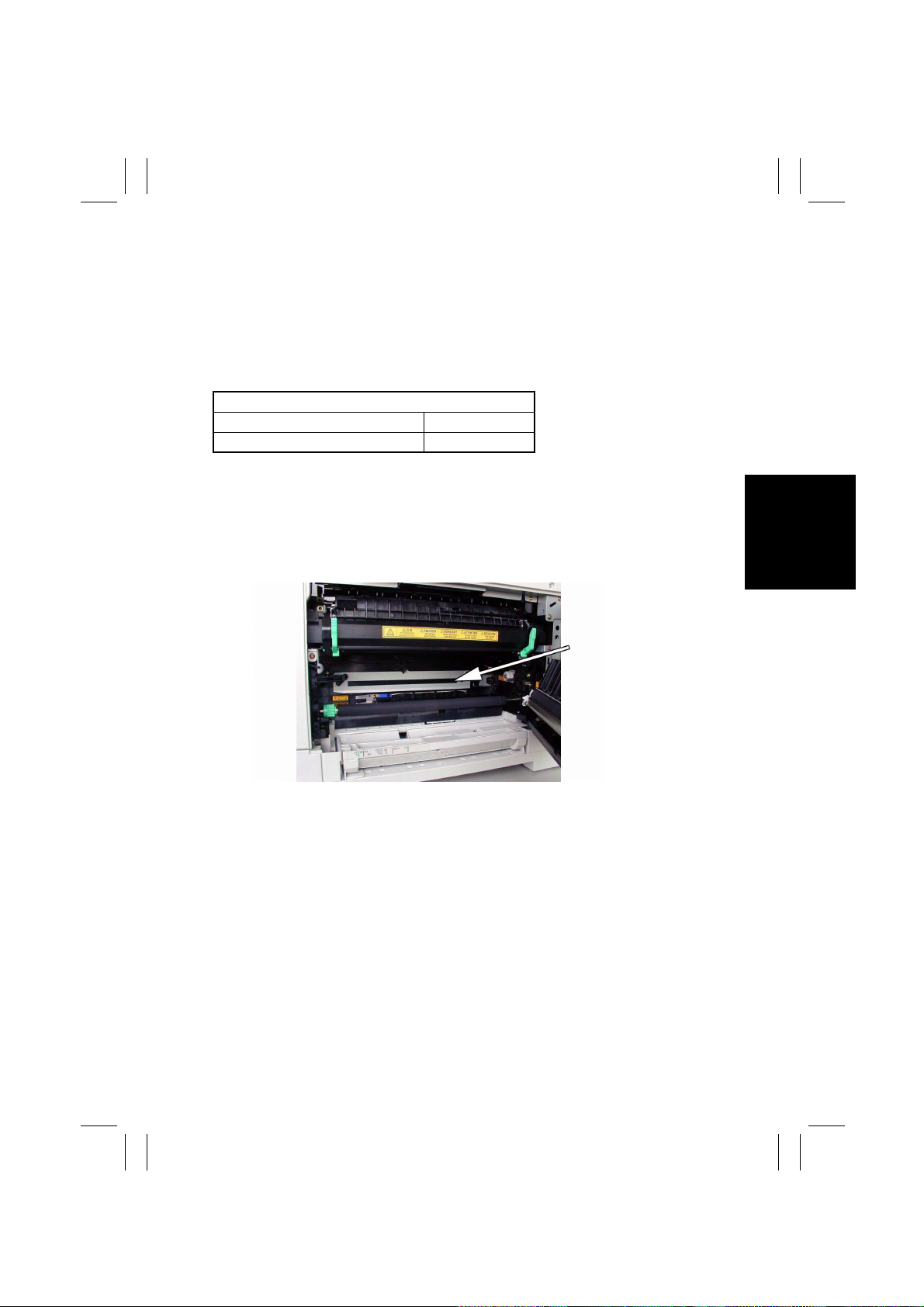
1-2. INTERNAL LASER RADIATION
Semiconductor laser
Maximum average radiation power(*) 26.4 µW
Wavelength 770-795 nm
*:Laser Aperture of the Print Head Unit
• This product employs a Class 3b laser diode that emits an invisible laser beam. The laser
diode and the scanning polygon mirror are incorporated in the print head unit.
• The print head unit is NOT A FIELD SERVICE ITEM. Therefore, the print head unit
should not be opened under any circumstances.
This figure Shows the view inside the Right Door
with the Imaging Unit removed.
D-1
Laser Aperture of
the Print Head Unit
Page 18

FrameMaker Ver.5.5E(PC) DIS/REASSEMBLY, ADJUSTMENT FOR Di152/Di183
01.09.03
the U.S.A., Canada
(CDRH Regulation)
• This machine is certified as a Class I Laser product under Radiation Performance Standard according to the Food, Drug and Cosmetic Act of 1990. Compliance is mandatory
for Laser products marketed in the United States and is reported to the Center for
Devices and Radiological Health (CDRH) of the U.S. Food and Drug Administration of
the U.S. Department of Health and Human Services (DHHS). This means that the device
does not produce hazardous laser radiation.
• The label shown to page D-4 indicates compliance with the CDRH regulations and must
be attached to laser products marketed in the United States.
CAUTION
Use of controls, adjustments or performance of procedures other than those specified in
this manual may result in hazardous radiation exposure.
Semiconductor laser
Maximum power of the laser diode 5 mW
Wavelength 770-795 nm
All Areas
CAUTION
Use of controls, adjustments or performance of procedures other than those specified in
this manual may result in hazardous radiation exposure.
Semiconductor laser
Maximum power of the laser diode 5 mW
Wavelength 770-795 nm
Denmark
ADVARSEL
Usynlig Laserstråling ved åbning, når sikkerhedsafbrydere er ude af funktion. Undgå
udsættelse for stråling. Klasse 1 laser produkt der opfylder IEC60825 sikkerheds kravene.
Halvlederlaser
Laserdiodens højeste styrke 5 mW
Bølgelængden 770-795 nm
D-2
Page 19

FrameMaker Ver.5.5E(PC) DIS/REASSEMBLY, ADJUSTMENT FOR Di152/Di183
01.09.03
Finland, Sweden
VARO!
Avattaessa ja suojalukitus ohitettaessa olet alttiina näkymättömälle lasersäteilylle. Älä
katso säteeseen.
LOUKAN 1 LASERLAITE
KLASS 1 LASER APPARAT
VAROITUS!
Laitteen Käyttäminen muulla kuin tässä käyttöohjeessa mainitulla tavalla saattaa altistaa
käyttäjän turvallisuusluokan 1 ylittävälle näkymättömälle lasersäteilylle.
Puolijohdelaser
Laserdiodin suurin teho 5 mW
Aallonpituus 770-795 nm
VARNING!
Om apparaten används på annat sätt än i denna bruksanvisning specificerats, kan användaren utsättas för osynlig laserstrålning, som överskrider gränsen för laserklass 1.
Halvledarlaser
Den maximala effekten för laserdioden 5 mW
Våglängden 770-795 nm
VARNING!
Osynlig laserstrålning när denna del är öppnad och spärren är urkopplad. Betrakta ej
strålen.
Norway
ADVERSEL
Dersom apparatet brukes på annen måte enn spesifisert i denne bruksanvisning, kan
brukeren utsettes for unsynlig laserstråling som overskrider grensen for laser klass 1.
Halvleder laser
Maksimal effekt till laserdiode 5 mW
Bølgelengde 770-795 nm
D-3
Page 20
FrameMaker Ver.5.5E(PC) DIS/REASSEMBLY, ADJUSTMENT FOR Di152/Di183
01.09.03
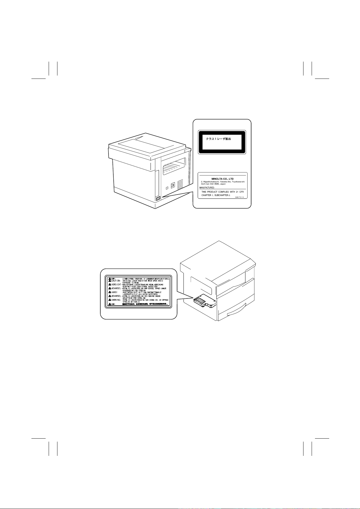
1-3. LASER SAFETY LABEL
• A laser safety labels is attached to the outside of the machine as shown below.
Laser safety label
For Europe
CLASS 1 LASER PRODUCT
LASER KLASSE 1
For United States
PRODUCT
1155O764AA
4022D038CA
4002O312CA
1-4. LASER CAUTION LABEL
• A laser caution label is attached to the inside of the machine as shown below.
4022D501AA
4022D027AA
1-5. PRECAUTIONS FOR HANDLING THE LASER EQUIPMENT
• When laser protective goggles are to be used, select ones with a lens conforming to the
above specifications.
• When a disassembly job needs to be performed in the laser beam path, such as when
working around the printerhead and PC Drum, be sure first to turn the copier OFF.
• If the job requires that the copier be left ON, take off your watch and ring and wear laser
protective goggles.
• A highly reflective tool can be dangerous if it is brought into the laser beam path. Use
utmost care when handling tools on the user’s premises.
D-4
Page 21
FrameMaker Ver.5.5E(PC) DIS/REASSEMBLY, ADJUSTMENT FOR Di152/Di183
01.09.03
2. SERVICE INSTRUCTIONS
2-1. IDENTIFICATION OF FUSES AND CIRCUIT BREAKERS
Control Board (PWB-C)
125 V 3 A
DC Power Supply (PU1)
100 V system 125 V 15 A (F2)
200 V system 250 V 6.3 A (F2)
Thermoswitch 1 (TS1)
250 V 7.5 A/125 V 15 A
4022D028AA
D-5
Page 22
FrameMaker Ver.5.5E(PC) DIS/REASSEMBLY, ADJUSTMENT FOR Di152/Di183
01.09.03
2-2. PARTS WHICH MUST NOT BE TOUCHED
(1) Red Painted Screws
Purpose of Application of Red Paint
Red painted screws show that the assembly or unit secured can only be adjusted or set at
the factory and shall not be readjusted, set, or removed in the field.
If it becomes unavoidably necessary to disassemble any of these assemblies and units,
disassembly may be done provided that the conditions permitting reassembly are met.
Note also that when two or more screws are used on the part in question, only one representative screw may be marked with red paint.
(2) Variable Resistors on Board
Do not turn the variable resistors on boards for which no adjusting instructions are given in
“ADJUSTMENT.”
Other Screws not Marked with Red Paint
<PH Unit>
PH Unit
<IR Unit>
Left side face
PH Unit base plate
Right side face
D-6
Page 23
FrameMaker Ver.5.5E(PC) DIS/REASSEMBLY, ADJUSTMENT FOR Di152/Di183
01.09.03
3. DISASSEMBLY/REASSEMBLY
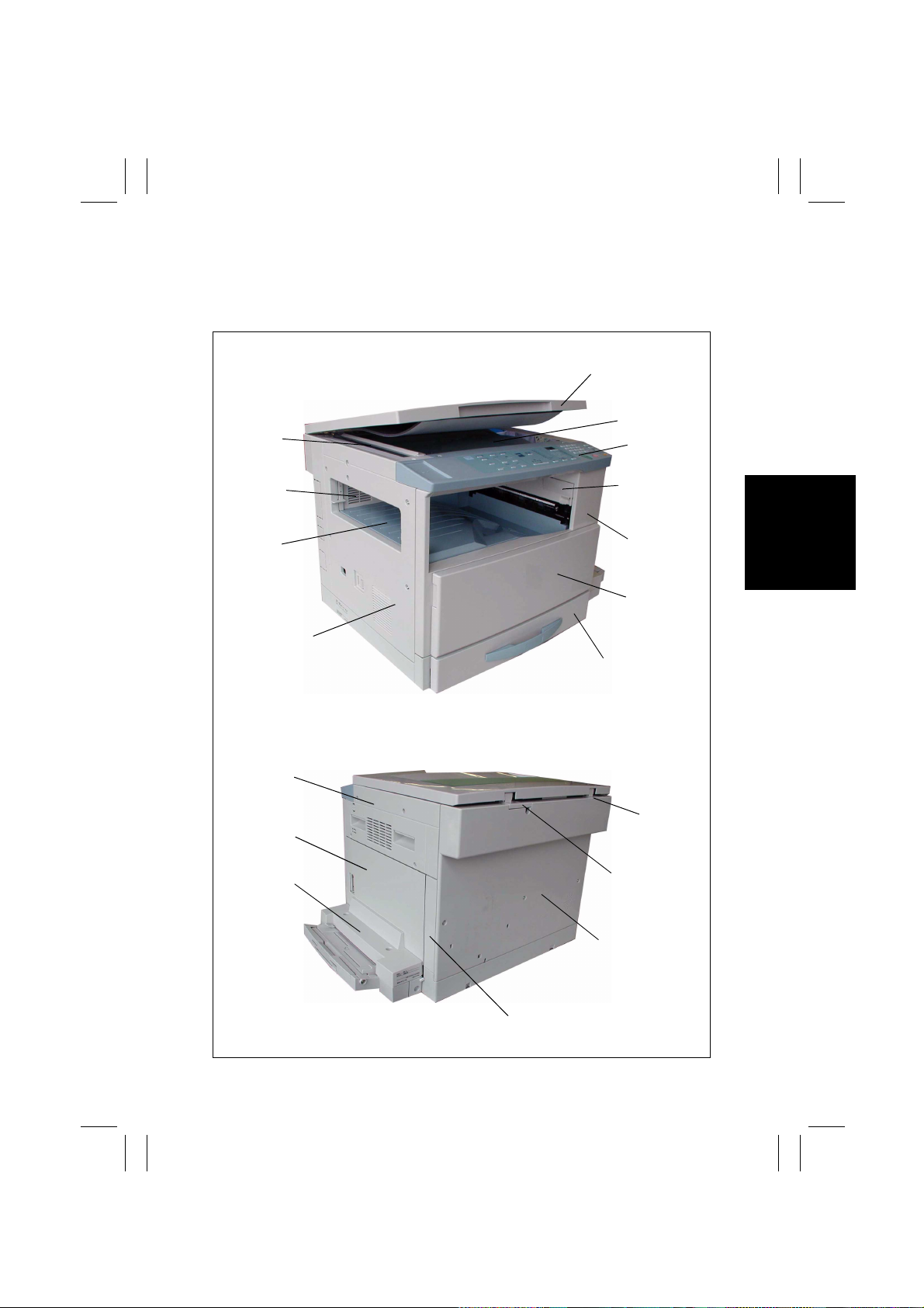
3-1. DOORS, COVERS, AND EXTERIOR P ARTS: IDENTIFICATION
AND REMOVAL PROCEDURES
1
2
11
3
9
10
18
17
16
4
5
6
8
7
12
13
D-7
14
15
Page 24
FrameMaker Ver.5.5E(PC) DIS/REASSEMBLY, ADJUSTMENT FOR Di152/Di183
01.09.03
No. Part Name Removal Procedure
1 Original Cover Pull the Original Cover straight up.
2 Original Glass
3 Control Panel
4 Right Inside Cover
5 Front Cover
6 Front Door
71st Tray
8 Left Cover
9 Upper Cover
10 Rear Inside Cover
11 ADF Glass Remove two ADF Glass mounting screws.
12 Left Hinge Remove no. 14. → Remove three Left Hinge mounting screws.
13 Right Hinge Remove no. 14. → Remove three Right Hinge mounting screws.
14 Rear Cover Remove six Rear Cover mounting screws.
15 Rear Right Cover
Multip le B ypass
16
Cover (when the
option is mounted)
17 Right Door
18 Right Cover
Remove no. 18. → Remove two holding brackets or no. 11 and
the Original Glass.
Remove two control panel mounting screws. → Remove two
ground wire mounting screws. → Remove one flat cable and
unplug one connector.
Remove no. 5. → Remove one Right Inside Cover mounting
screw.
Remove no. 3. → Open the Front Door and remove six Front
Cover mounting screws.
Open the Front Door and remove one band mounting screw. →
Snap off one C-clip.
Slide out the 1st Tray. → Remove the fixing brackets on the right
and left.
Remove no. 3. → Remove no. 5. → Remove no. 14. → Remove
five Left Cover mounting screws.
Remove no. 3. → Remove no. 5. → Remove no. 14. → Remove
no. 8. → Remove two screws and two Upper Cover mounting
screws.
Remove no. 3. → Remove no. 5. → Remove no. 14. → Remove
no. 8. → Remove no. 9. → Remove no. 4. → Remove two Rear
Inside Cover mounting screws.
Remove no. 14. → Remove one Rear Right Cover moun ting
screw.
Remove two Multiple Bypass Cover mounting screws.
Remove no. 14. → Remove no. 15. → Remove three Right Door
mounting screws.
Remove no. 3. → Remove no. 5. → Remove no. 14. → Remove
four Right Cover mount ing screws.
D-8
Page 25
FrameMaker Ver.5.5E(PC) DIS/REASSEMBLY, ADJUSTMENT FOR Di152/Di183
01.09.03
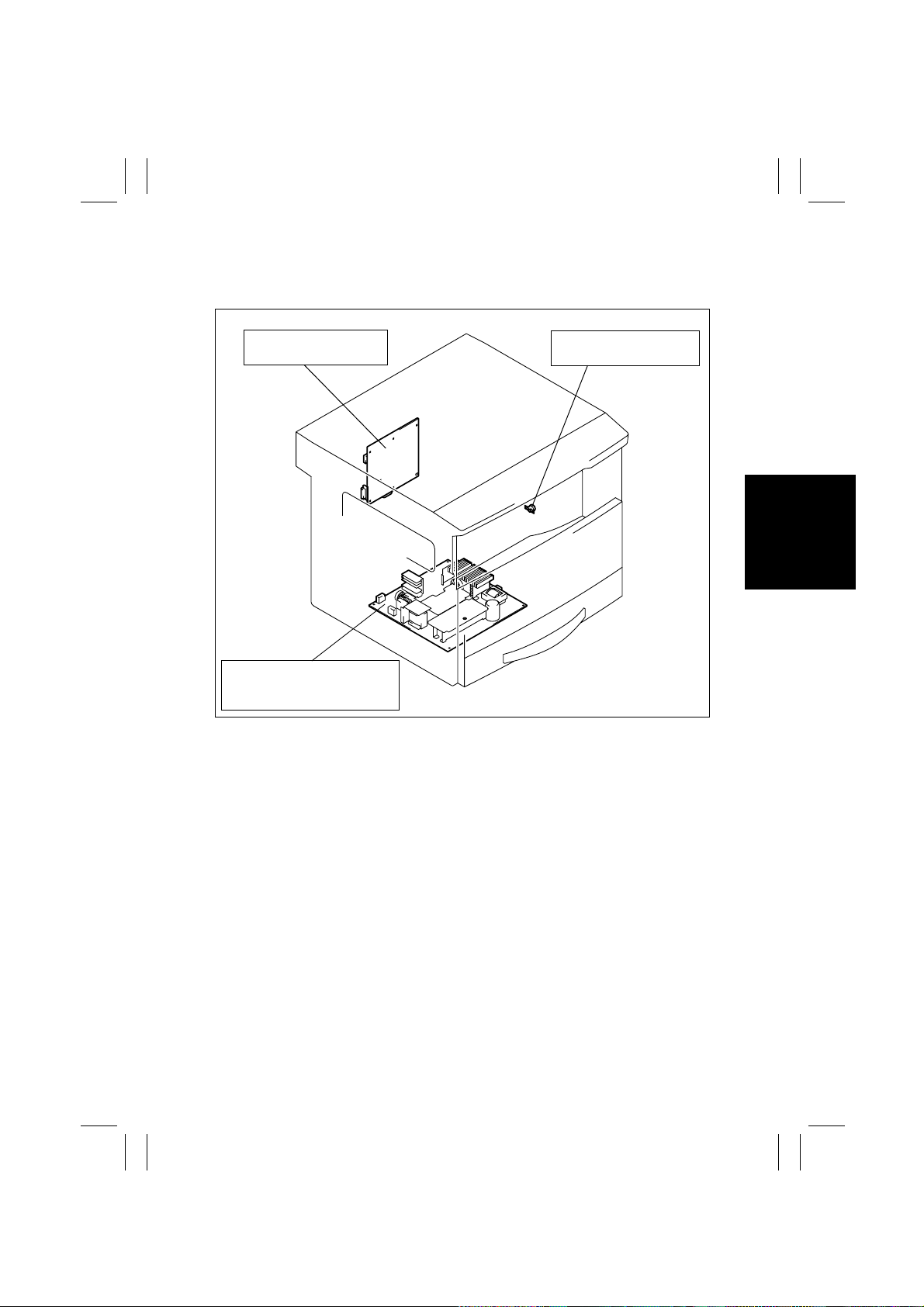
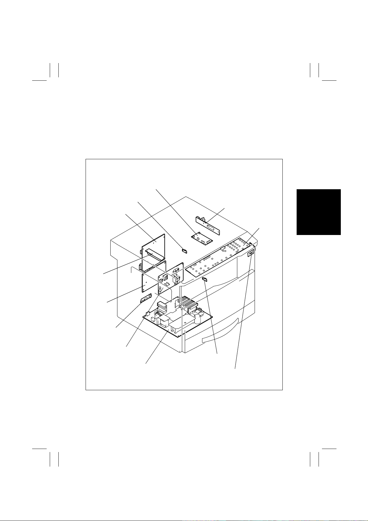
3-2. REMOVAL OF CIRCUIT BOARDS AND OTHER ELECTRICAL
COMPONENTS
• When removing a circuit board or other electrical component, refer to “PRECAUTIONS
FOR HANDLING THE PWBs” and follow the corresponding removal proc edures.
• The removal procedures given in the following omit the removal of connectors and
screws securing the circuit board support or circuit board.
• Where it is absolutely necessary to touch the ICs and other electrical components on the
board, be sure to ground your body.
PWB-A
Job Tray (JS-202): Option
Shifting Unit (OT-103): Option
PWB-R1
PWB-J
PWB-C
PU3
PU2
PWB-A
PWB-I
HV1
4022D029AA
PWB-R2
PU1
PWB-B
Job Tray (JS-202): Option
D-9
Page 26
FrameMaker Ver.5.5E(PC) DIS/REASSEMBLY, ADJUSTMENT FOR Di152/Di183
01.09.03
Symbol Part Name Removal Procedure
PWB-A Master Board
PWB-C Control Board
PWB-I
PWB-J CCD Board
PWB-R1 Fusing Board Remove the Fusing Unit. → PWB-R1
PWB-R2
PU1 DC Power Supply
PU2 Inverter Board
PU3 Control Panel
HV1 High Voltage Unit
Job Tray (JS-202): Option
Symbol Part Name Removal Procedure
PWB-A Main Boar d
PWB-B Paper Detecting Board☞ D-48
Paper Size Detecting
Board
Pre-Image Transfer
Board
☞
D-10
☞
D-11
Remove the Rear Cover. → Remove t he PWB Assy. →
Remove two screws and the PWB-I Assy. → PWB-I
☞
D-23
✽
Remove the CCD Unit as a unit.
Open the Right Door. → PWB-R2
☞
D-13
☞
D-23
Remove two control panel mounting screws. → Remove
two ground wire mounting screws. → Remove one flat
cable and unplug one connector. → PU3
☞
D-11
☞
D-46
Shifting Unit (OT-103): Option
Symbol Part Name Removal Procedure
PWB-A Main Boar d
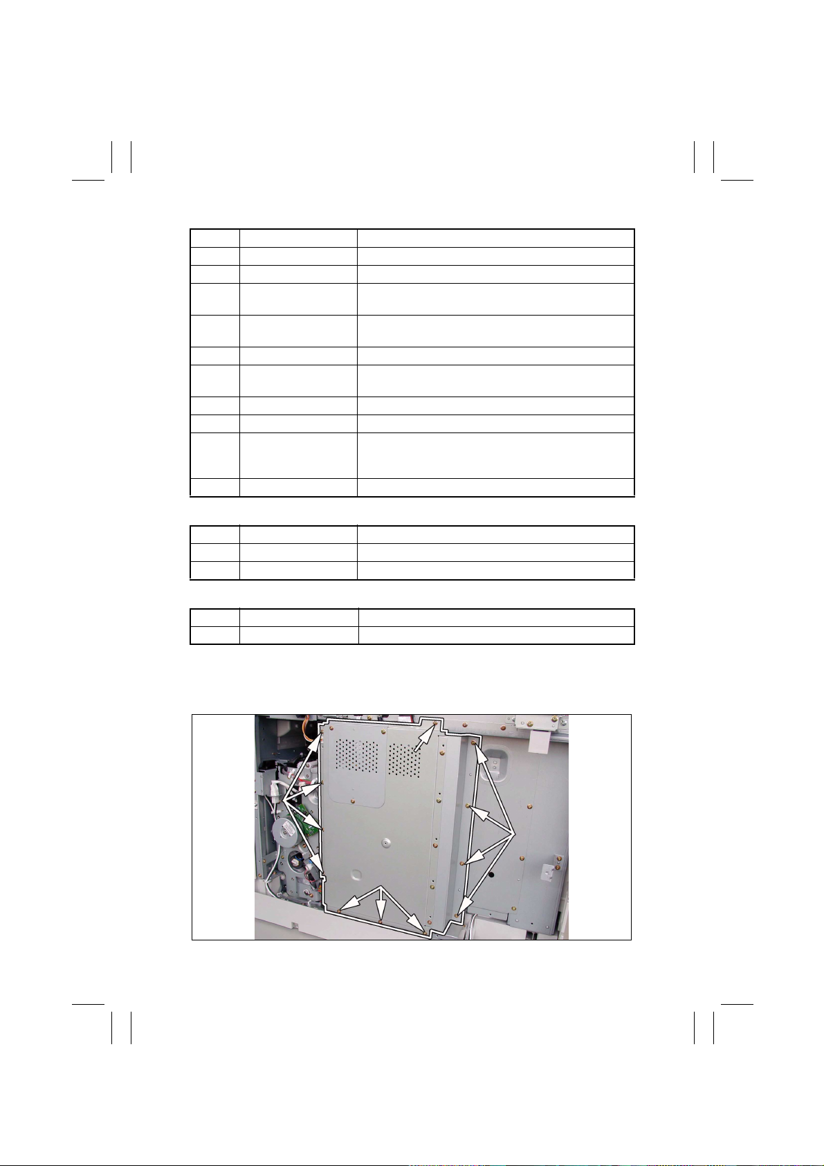
(1) Removal of the Master Board
1. Remove the Rear Cover.
2. Remove 12 screws and the PWB Cover Assy.
☞
D-49
D-10
Page 27
FrameMaker Ver.5.5E(PC) DIS/REASSEMBLY, ADJUSTMENT FOR Di152/Di183
01.09.03
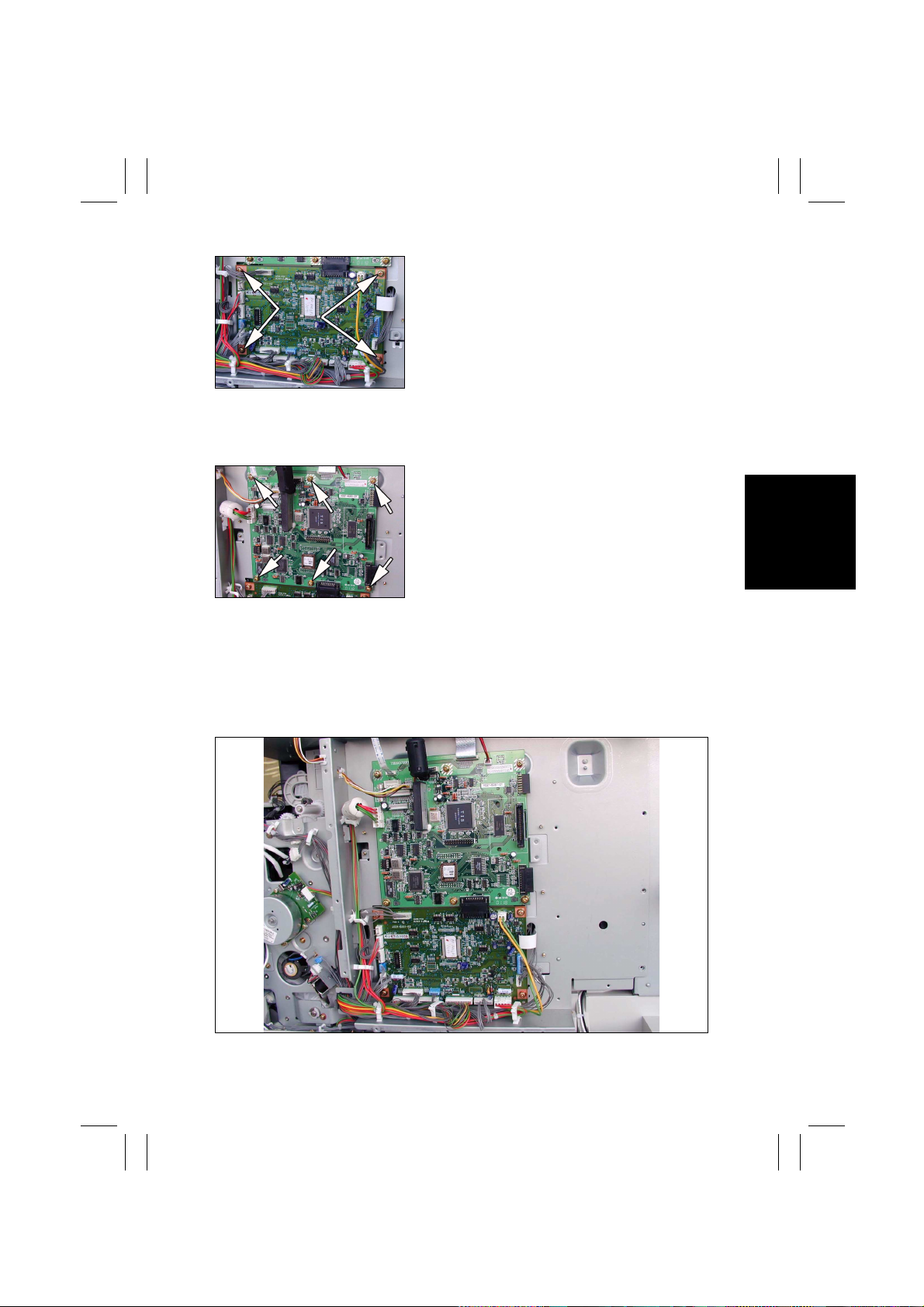
3. Unplug all connectors (but PJ20) from the Master
Board.
4. Remove f our screws and the Master Board.
(2) Removal of the Control Board
1. Remove the Rear Cover.
2. Remove the PWB Cover Assy.
3. Unplug all connectors from the Control Board.
4. Remove six screws and the Control Board.
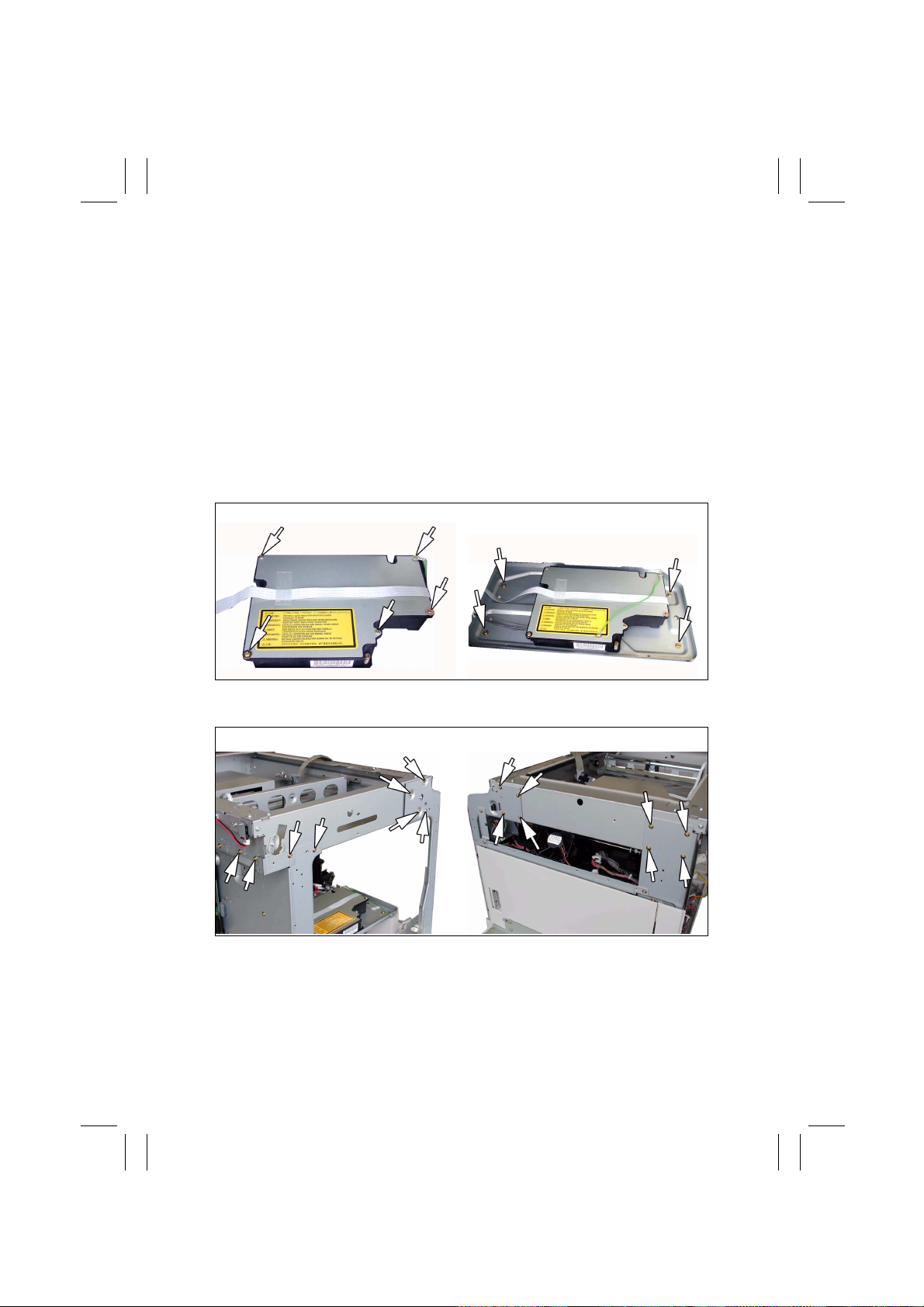
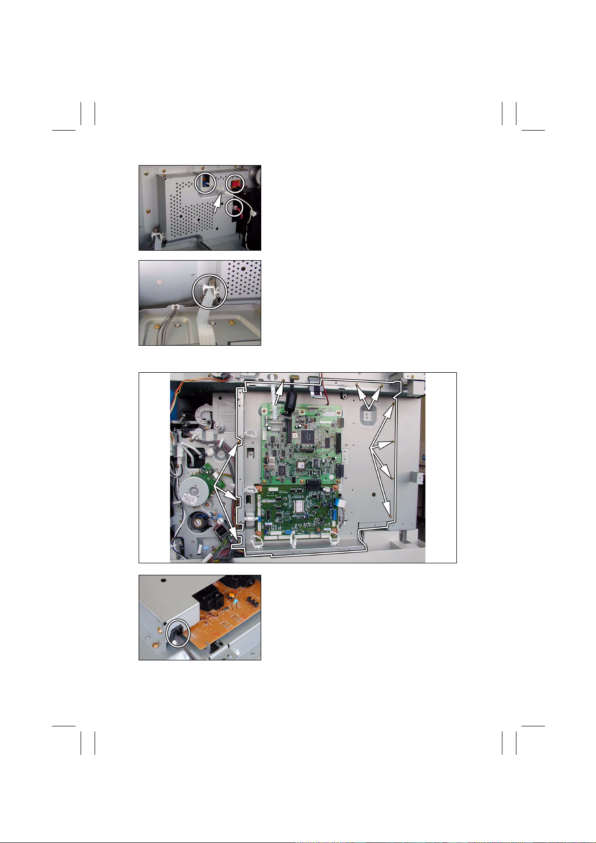
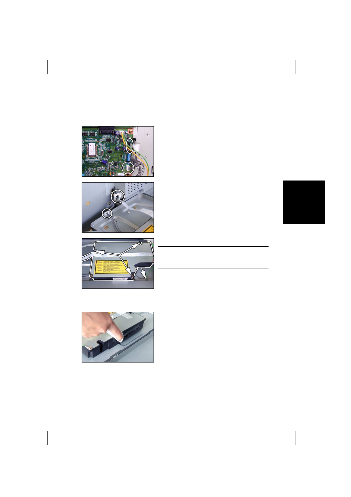
(3) Removal of the High Voltage Unit
1. Remove the control panel, Front Cover, Rear Cover, Left Cover, Upper Cover, Right
Inside Cover, and Rear Inside Cover.
2. Remove the PWB Cover Assy.
3. Unplug all connectors from the Master Board (except for PJ20) and from the Control
Board.
4. Remove the harness from seven wiring saddles and two edge covers.
D-11
Page 28
FrameMaker Ver.5.5E(PC) DIS/REASSEMBLY, ADJUSTMENT FOR Di152/Di183
01.09.03
5. Unplug three connectors from the High Voltage
Unit and remove the harness from one wiring
saddle.
6. Remove the harness from one wiring saddle.
7. Remove ten screws and the PWB Assy.
8. Remove the harness from one wiring saddle of
the High Voltage Unit cover.
D-12
Page 29

FrameMaker Ver.5.5E(PC) DIS/REASSEMBLY, ADJUSTMENT FOR Di152/Di183
01.09.03
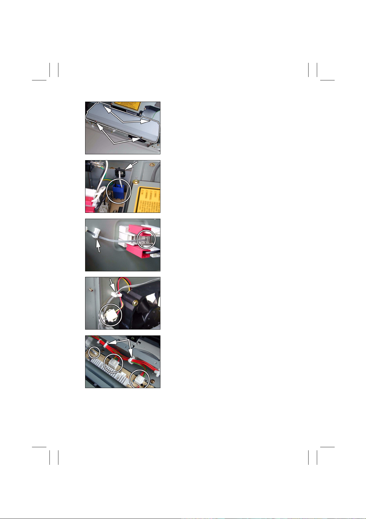
9. Remove nine screws and the High Voltage Unit
cover.
10. Unplug two connectors from the High Voltage
Unit.
11. Remove two screws and the High Voltage Unit.
(4) Removal of the DC Power Supply
1. Remove the control panel, Front Cover, Rear Cover, Left Cover, and Upper Cover.
2. Unplug two connectors of the Hopper Assy.
3. Remove two Hopper mounting screws on the
right.
4. Remove two Hopper mounting screws on the left
and the Hopper Assy.
5. Remove three screws and the Power Supply
Right Cover.
D-13
Page 30
FrameMaker Ver.5.5E(PC) DIS/REASSEMBLY, ADJUSTMENT FOR Di152/Di183
01.09.03
6. Remove f our screws and the Power Supply Left
Cover.
7. Unplug one connector and remove the harness
from one edge cover.
8. Unplug one connector and remove the harness
from one wiring saddle.
9. Unplug one connector and remove the harness
from one wiring saddle.
10. Unplug three connectors and remove the harness
from two wiring saddles.
D-14
Page 31

FrameMaker Ver.5.5E(PC) DIS/REASSEMBLY, ADJUSTMENT FOR Di152/Di183
01.09.03
11. Remove two screws.
12. Remove two screws.
13. Remove f our screws and the DC Power Supply.
D-15
Page 32

FrameMaker Ver.5.5E(PC) DIS/REASSEMBLY, ADJUSTMENT FOR Di152/Di183
01.09.03
3-3. MAINTENANCE SCHEDULE
Paper take-up failure, dou-
ble feed
Paper take-up failure, dou-
Double feed
ble feed
Double feed
Failure to remove toner off
completely, filming
Dirty image
Dirty image
Paper misfeed
Image noise (white lines)
Counter (*3) Associated Problems
Ref.
Part No. Qty
(K)
Maintenance Cycle
PM Parts
1st Tray
D-18
Page
☞
150 4021-3012-XX 1
Clean Replace
Paper Take-Up Roll (1st Tray)
D-18
☞
Paper Separator Roll Assy 150 4658-0151-XX 1
Bypass Tray
IU Life
—
D-42
D-42
D-19
D-19
☞
☞
150 4658-0151-XX 1
150 4687-3257-XX 1
When a
malfunction
occurs
Multi Bypass Separator Roll Assy
(Multiple Bypass)
Multi Bypass Paper Take-Up Roll
(Multiple Bypass)
☞
Paper Dust Remover Assy (*1) 40 4021-0151-XX 1
☞
Right Synchronizing Roller — — —
D-19
☞
Left Synchronizing Roller — — —
D-20
☞
Bypass Transport Roller — — —
D-21
☞
Mirrors and lens 80 — — —
IRScanner rails/bushings 80 — — —
D-22
☞
D-21
☞
When a
Original Glass 80 — — —
— Image noise (white lines)
D-29
D-30
☞
☞
———
40 — 1
malfunction
occurs
When a
malfunction
PC Drum
IU Life
D-32
D-32
D-32
D-33
☞
PC Drum Charge Corona Assy — 40 4021-0306-XX 1
☞
Developer (starter) — 40 — 1
D-33
☞
Ds collar 40 — — —
☞
☞
occurs
PC Drum Paper Separator Finger 40 — — —
Cleaning Blade — 40 4163-5602-XX 1
Paper Take-Up/
Transport Section
Optical Section
PH Section PH window
Imaging Unit (*2)
D-16
Page 33

FrameMaker Ver.5.5E(PC) DIS/REASSEMBLY, ADJUSTMENT FOR Di152/Di183
01.09.03
Misfeed due to paper not
properly separated from
PC Drum
Counter (*3) Associated Problems
Ref.
Page
Part No. Qty
(K)
Maintenance Cycle
PM Parts
IU Life
Ozone Filter
Image Trans-
fer Roller/
Fusing Unit
— Dirty image
—
Image Trans-
fer Roller/
Fusing Unit
D-33
D-32
D-34
D-31
D-31
D-36
D-36
D-36
D-37
☞
☞
☞
☞
☞
☞
☞
☞
1156-4118-XX 1
150
Clean Replace
—
(Areas other than Europe) 300
———
When a
malfunction
occurs
☞
D-37
☞
(200-V system) — 150 4021-0322-XX 1
Developer Scattering Prevention Plate 40 — — —
Pre-Image Tran sfer Upper Guid e Plat e 40 — — —
Ozone Filter (Europe)
Charge Neutralizing Sheet — 40 4163-4302-XX 1
Imaging Unit (*2)
Image Transfer Roller Assy — 150 4021-0315-XX 1
Pre-Image Transfer Lower Guide Plate
Image Transfer
Section
Fusing Unit (100-V system) — 150 4021-0321-XX 1
Charge Neutralizing Plate — — —
Fusing Section
*1: Replace at 40K for recommended plain paper. Clean when the Paper Dust Remover is full of paper dust for paper of other types.
*2: The life of the Imaging Unit (except f or the Oz one Filter) is determined by the period of time through which the PC Drum has turned (as
translated to an equivalent distance traveled). The maintenance cycle in the table represents the number of copies made in the standard
copy mode (A4C, 2PJ) which may differ depending on conditions in which the copiers are used among different users.
*3: For details, see SWITCHES ON PWBs, TECH. REP. SETTINGS.
NOTE
• k = 1,000 copies
• The contents of this maintenance schedule are subject to change without notice.
• For part numbers, see Parts Manual and Parts Modification Notice.
D-17
Page 34

FrameMaker Ver.5.5E(PC) DIS/REASSEMBLY, ADJUSTMENT FOR Di152/Di183
01.09.03
3-4. PAPER TAKE-UP/TRANSPORT SECTION
(1) Removal of the Paper Separator Roll Assy and Paper Take-Up Roll
1. Slide out the 1st Tray.
2. Remove two screws and the Paper Separator
Roll Assy.
3. Press down the Paper Lif ting Plate.
4. Snap off one C-clip from the Paper Take-Up Roll
Assy.
5. Slide the Paper Take-Up Roll Assy to the rear so
that it can be pulled off the bushing at the front.
6. Snap off one C-clip and remove the Paper TakeUp Roll.
(2) Cleaning of the Pa pe r Sepa r a tor Roll
1. Remove the Paper Separator Roll Assy.
2. Using a soft cloth dampened with alcohol, wipe
the Paper Separator Roll clean of dirt.
(3) Cleaning of the Paper Take-Up Roll
1. Slide out the 1st Tray.
2. Remove the Paper Separator Roll Assy.
3. Using a soft cloth dampened with alcohol, wipe
the Paper Take-Up Roll clean of dirt.
D-18
Page 35

FrameMaker Ver.5.5E(PC) DIS/REASSEMBLY, ADJUSTMENT FOR Di152/Di183
01.09.03
(4) Cleaning of the Right and Left Synchronizing Rollers
1. Remove the Imaging Unit.
2. Using a soft cloth dampened with alcohol, wipe
the Right and Left Synchronizing Rollers clean of
dirt.
(5) Removal of the Paper Dust Remover Assy
1. Remove the Imaging Unit.
2. Remove two screws and the st opper.
3. Remove the 1st Tray.
4. Remove one screw and the Synchronizing Roller Sensor Assy.
NOTE
• Do not unplug the sensor harness connector.
5. Remove three screws and the Paper Dust
Remover Assy.
D-19
Page 36

FrameMaker Ver.5.5E(PC) DIS/REASSEMBLY, ADJUSTMENT FOR Di152/Di183
01.09.03
(6) Cleaning of the Paper Dust Remover
1. Remove the Paper Dust Remover Assy.
2. Using a brush, whisk dust and dirt off the Paper
Dust Remover.
(7) Cleaning of the Bypass Transport Roller
1. Remove the Imaging Unit.
2. Remove two screws, unplug one connector, and remove the Bypass Transport Roller
Assy.
3. Using a soft cloth dampened with alcohol, wipe
the Bypass Transport Roller clean of dirt.
4. Using a soft cloth dampened with alcohol, wipe
the rolls clean of dirt.
D-20
Page 37

FrameMaker Ver.5.5E(PC) DIS/REASSEMBLY, ADJUSTMENT FOR Di152/Di183
01.09.03
3-5. OPTICAL SECTION
(1) Cleaning of the Original Glass and ADF Glass
1. Using a soft cloth dampened with alcohol, wipe
the Original Glass and ADF Glass clean of dirt.
(2) Cleaning of Mirrors
1. Remove the Original Glass.
2. Using a soft cloth dampened with alcohol, wipe
the mirrors clean of dirt.
(3) Cleaning of the Lens
1. Remove the Original Glass.
2. Remove 15 screws and the CCD Unit cover.
D-21
Page 38

FrameMaker Ver.5.5E(PC) DIS/REASSEMBLY, ADJUSTMENT FOR Di152/Di183
01.09.03
3. Using a soft cloth dampened with alcohol, wipe
the Lens clean of dirt.
(4) Cleaning of the CCD Sensor
1. Remove the Original Glass.
2. Remove 15 screws and the CCD Unit cover.
3. Remove the Lens cover.
4. Using a soft cloth dampened with alcohol, wipe
the CCD Sensor clean of dirt.
(5) Cleaning of the Scanner Rails/Bushings
1. Remove the Original Glass.
2. Using a soft cloth dampened with alcohol, wipe
the Scanner rails/bushings clean of dirt.
NOTE
• After the Scanner rails/bushings have been
cleaned, apply oil (copier lubricant A or FLOIL
947P).
D-22
Page 39

FrameMaker Ver.5.5E(PC) DIS/REASSEMBLY, ADJUSTMENT FOR Di152/Di183
01.09.03
(6) Removal of the CCD Unit
1. Remove the Original Glass.
2. Remove 15 screws and the CCD Unit cover.
3. Unplug one connector.
4. Remove three screws and the CCD Unit.
NOTE
• NEVER attempt to loosen or remove screws that
are not specified when removing the CCD Unit.
<<Reinstallation of the CCD Unit>>
• Temporarily secure the CCD Unit with each of the
screws at the center of each slot.
• After the CCD Unit has been installed, adjust the
position of the CCD Unit.
☞
D-65
(7) Removal of the Scanner, Exposure Lamp , and Inverter Board
1. Remove the control panel, Front Cover, Rear Cover, and Original Glass.
2. Remove the foam seal and mylar, one each at the front and rear.
NOTE
• Ready a new foam seal and mylar and affix them after the procedure.
Front
Foam Seal
Mylar
Foam Seal
Rear
Mylar
D-23
Page 40

FrameMaker Ver.5.5E(PC) DIS/REASSEMBLY, ADJUSTMENT FOR Di152/Di183
01.09.03
3. Remove two Scanner mounting screws (to which
no red paint has been applied).
4. Remove one screw and the cable holder.
5. Remove the flat cable from the Inverter Board
and then remove the Scanner.
6. Unplug one connector from the Inverter Board.
7. Remove two screws and the Inverter Board.
8. Remove two screws and the Exposure Lamp.
D-24
Page 41

FrameMaker Ver.5.5E(PC) DIS/REASSEMBLY, ADJUSTMENT FOR Di152/Di183
01.09.03
(8) Removal of the Scanner Drive Cables
1. Remove the control panel, Front Cover, Rear Cover, Left Cover, Right Cover, Original
Glass, and ADF Glass.
2. Remove the Scanner.
NOTE
• Remove the two red painted screws to remove the Scanner in this step.
3. Remove two screws and the Exposure Lamp.
4. Loosen three screws to free the Scanner Motor
Assy.
5. Unhook the spring from the cable hooks at the
front and rear.
6. Remove the front cable from the cable pulley.
D-25
Page 42

FrameMaker Ver.5.5E(PC) DIS/REASSEMBLY, ADJUSTMENT FOR Di152/Di183
01.09.03
7. Remove the rear cable from the cable pulley.
8. Snap off one C-ring from the front side of the pulley assy.
9. Snap off one C-ring from the rear side of the pulley assy.
10. Remove the belt and the pulley assy.
11. Remove two screws and the pulley.
12. Remove the rear cable.
D-26
Page 43

FrameMaker Ver.5.5E(PC) DIS/REASSEMBLY, ADJUSTMENT FOR Di152/Di183
01.09.03
(9) Winding of the Scanner Drive Cables
Rear
Front
4022D003AA
1. Wind the cable around the rear cable pulley of the pulley assy from side B toward side A
and then secure the cable with tape.
2. Wind the cable around the front cable pulley of the pulley assy from side A toward side
B and then secure the cable with tape.
NOTE
• Make sure that no part of the cable rides on the other.
Bead Position
➃
B
➂
➁
➀
Winding
Direction on Side B
4022D005AA
Winding
Direction on
Side A
A
Rear
➂
B
➁
➃
➀
Winding Direction on Side B
Front
Winding Direction
on Side A
A
➀➁➂➃
Bead Position
3. Secure the pulley to the rear cable pulley using
two screws.
NOTE
• Make sure that the pulley is doweled to the cable
pulley.
D-27
➀➁➂➃
Page 44

FrameMaker Ver.5.5E(PC) DIS/REASSEMBLY, ADJUSTMENT FOR Di152/Di183
01.09.03
4. Mount the pulley assy using two C-rings.
4022D006AB
5. Wind the cable at the front.
6. Hook the spring onto the cable hook and hook the spring onto the frame.
7. Wind the cable in the rear.
8. Secure the cables at the front and rear with a spring.
9. Temporarily secure the Scanner to the front and
rear cables.
10. Perfor m the Focus-Positioning of the Scanner
and 2nd/3rd Mirrors Carriage.
☞
D-64
4022D009AA
4022D007AB
4022D008AB
D-28
Page 45
FrameMaker Ver.5.5E(PC) DIS/REASSEMBLY, ADJUSTMENT FOR Di152/Di183
01.09.03
3-6. PH
(1) Removal of the PH Unit
1. Remove the control panel, Front Cover, Rear Cover, Left Cover, and Upper Cover.
2. Remove the PWB Cover Assy.
3. Remove one flexible harness and unplug one
connector from the Master Board.
4. Remove the harness from one edge cover and
one wiring saddle.
5. Remove one screw and the ground wire.
NOTE
• To remove the ground wire, remove the screw
installed on the copier side.
6. Remove three screws and the PH Unit.
(2) Cleaning of the PH Window
1. Remove the Front Cover, Rear Cover, Left Co ver, and Upper Cover.
2. Wipe the PH window clean of dirt using a soft
cloth.
D-29
Page 46

FrameMaker Ver.5.5E(PC) DIS/REASSEMBLY, ADJUSTMENT FOR Di152/Di183
01.09.03
3-7. Imaging Unit (IU)
NOTE
• When loading developer as part of the IU replacement procedure or when changing the
developer, remove the Toner Bottle and run “ATDC Sensor Automatic Adjustment” (F8)
twice to allow toner in the Spent Toner Recycling Duct and Toner Conveying Duct into the
Developer Mixing Chamber before removing the IU.
(1) Removal of the IU
1. Open the Right Door.
2. Open the Front Door.
3. Remove two screws and, holding onto the handle
of the IU, take off the IU.
NOTE
• Before installing the IU, be sure to fully open the
Handle
Right Door.
If the IU is installed with the Right Door left ajar, the
PC Drum protective shutter will not open, interfering with the Image Transfer Roller gear, thus producing noise.
• When inserting the IU, do that slowly and, when
you are sure that the drum gear contacts its mating
part, push the IU all the way into position. If this
step is done all at once, the drum gear could be
damaged.
(2) Disassembly of the IU
<Separating the Cleaning Assy from Developing Assy>
1. Remove one screw in the rear of the IU and
remove the harness cover.
2. Remove two screws in the rear of the IU.
D-30
Page 47

FrameMaker Ver.5.5E(PC) DIS/REASSEMBLY, ADJUSTMENT FOR Di152/Di183
01.09.03
3. Remove two screws at the front of the IU.
4. Widen flaps on both ends (marked with A in the
illustration on the left) of the Cleaning Assy in the
direction of arrow and turn to take off the Clean-
A
A
ing Assy .
5. Unplug one connector of the Main Erase.
<Removal of the PC Drum>
<Removal of the Ozone Filter>
6. Remove two screws and the pivot shaft.
7. Remove the PC Drum.
NOTE
• When the PC Drum has been replaced, apply a
coat of toner to the surface of the PC Drum.
☞
D-34
8. Remove two screws and the Main Erase.
D-31
Page 48

FrameMaker Ver.5.5E(PC) DIS/REASSEMBLY, ADJUSTMENT FOR Di152/Di183
01.09.03
9. Remove the Ozone Filter.
<Removal of the PC Drum Charge Corona Assy>
10. Turn the holder in the rear in the direction of the
arrow to remove it from the side bracket.
11. Slide out the PC Drum Charge Corona in the
direction of the arrow.
<Removal of the Charge Neutralizing Sheet and Cleaning Blade>
12. Remove three screws, the Charge Neutralizing
Sheet, and Cleaning Blade.
NOTE
• When securing the Cleaning Blade and Charge
Neutralizing Sheet, tighten screws in the order of
one on one edge, one at the center, and one on
the other edge.
• When the Cleaning Blade has been replaced,
apply a coat of toner to the surface of the PC
Drum.
☞
D-34
<Cleaning of the PC Drum Paper Separator Fingers>
13. Using a soft cloth dampened with alcohol, wipe
the Paper Separator Fingers clean of dirt.
D-32
Page 49

FrameMaker Ver.5.5E(PC) DIS/REASSEMBLY, ADJUSTMENT FOR Di152/Di183
01.09.03
<Cleaning of the Ds Collars>
14. Using a soft cloth dampened with alcohol, wipe
the Ds Collars clean of dirt.
<Cleaning of the Developer Scattering Prevention Plate>
15. Remove three screws and the Developer Scattering Prevention Plate.
16. Using a brush, whisk dust and dirt off the surface
of the Developer Scattering Prevention Plate.
<Replacement of the Developer>
17. Dump the developer.
<<How to Dump Developer>>
• Dump developer on the Sleeve Roller by turning
the gear in the direction of the arrow with the
Developing Unit tilted as shown.
• Note at this time that turning the gear backward
could damage the mylar for cleaning the ATDC
Sensor.
• Dump developer until almost no developer sticks to
the Sleeve Roller.
D-33
Page 50

FrameMaker Ver.5.5E(PC) DIS/REASSEMBLY, ADJUSTMENT FOR Di152/Di183
01.09.03
18. Pour one packet of developer.
NOTE
• Shake the packet of developer well before pouring.
• When the developer has been replaced, run
“ATDC Sensor Automatic Adjustment.”
☞
D-61
<Cleaning of the Pre-Image Transfer Guide Plate>
19. Using a soft cloth dampened with alcohol, wipe
the Pre-Image Transfer Guide Plate clean of dirt.
(3) Application of Toner
NOTE
• Perform these steps when the PC Drum and/or Cleaning Blade have been replaced.
1. With the Cleaning Assy separated from the
Developing Assy, install the PC Positioning Jig in
the rear of the Developing Ass y.
NOTE
• Ready the PC Positioning Jig (Pivot Shaft) sepa-
rately. (It can be ordered. For details, see the
4022D034AA
Parts Manual.)
2. Using a brush, apply a light coat of toner to the
surface of the PC Drum.
4021U008AB
D-34
Page 51

FrameMaker Ver.5.5E(PC) DIS/REASSEMBLY, ADJUSTMENT FOR Di152/Di183
01.09.03
<<Area to which toner is to be applied>>
10 - 15 mm 20 - 25 mm
20 - 30 mm
PC Drum
4021U057AA
3. Hold both ends of the PC Drum with your both
hands and turn the PC Drum a half turn in the
direction of the arrow.
4021U009AA
(4) Replacement of the ATDC Sensor
1. Divide the IU into the Cleaning Assy and Developing Assy.
2. Remove the Developer Scattering Prevention Plate and dump developer.
3. Unplug one connector, and remove one screw
and the ATDC Sensor.
4. Install the ATDC Sensor.
5. Pour de veloper.
6. Reinstall the Developer Scattering Prevention Plate.
7. Mount the Cleaning Assy to the Developing Assy .
8. Install the IU in the copier and run F8 operation.
9. Enter the adjustment value on the Adjust Label.
D-35
Page 52

FrameMaker Ver.5.5E(PC) DIS/REASSEMBLY, ADJUSTMENT FOR Di152/Di183
01.09.03
3-8. IMAGE TRANSFER SECTION
(1) Removal of the Image Transfer Roller Assy
1. Open the Right Door.
2. Loosen one fixing bracket mounting screw.
3. Turn to remove the Pre-Image Transfer Upper
Guide Plate.
NOTE
• When reinstalling the fixing bracket, make sure
that the hook of the fixing brack et fit s into the slot in
the Pre-Image Transfer Upper Guide Plate.
(2) Cleaning of the Pre-Image Transfer Lower Gui de Plate
1. Open the Right Door.
2. Using a soft cloth dampened with alcohol, wipe
the Pre-Image Transfer Lower Guide Plate clean
of dirt.
(3) Cleaning of the Charge Neutralizing Plate
1. Open the Right Door.
2. Using a soft cloth dampened with alcohol, wipe
the Charge Neutralizing Plate clean of dirt.
NOTE
• Use care not to allow the Image Transfer Roller to
be touched with alcohol.
• Do not allow the soft cloth to be caught by the tip of
the Charge Neutralizing Plate.
D-36
Page 53

FrameMaker Ver.5.5E(PC) DIS/REASSEMBLY, ADJUSTMENT FOR Di152/Di183
01.09.03
3-9. FUSING SECTION
(1) Removal of the Fusing Unit
1. Remove the control panel.
NOTE
• In this step, free the control panel without removing one flat cable and two ground wires
and unplugging one connector.
2. Remove the Front Co ver, Rear Cover, and Rear Right Cover.
3. Unplug two connectors of the Fusing Unit.
4. Open the Right Door.
5. Remove f our screws and the Fusing Unit.
(2) Disassembly of the Fusing Unit
<Removal of the Thermoswitch>
1. Remove two screws and the thermoswitch.
D-37
Page 54

FrameMaker Ver.5.5E(PC) DIS/REASSEMBLY, ADJUSTMENT FOR Di152/Di183
01.09.03
<Removal of the Right Fusing Roller>
2. Unhook the pressure springs at the front and
rear.
3. Remove two shoulder screws, two washers, and
the Right Roller Assy.
4. Remove the Right Roller .
<Removal of the Fusing Heater Lamp>
5. Remove the Pressure Lever Assemblies at the
front and rear.
6. Remove two screws and the Fus ing Entrance
Guide Plate.
D-38
Page 55

FrameMaker Ver.5.5E(PC) DIS/REASSEMBLY, ADJUSTMENT FOR Di152/Di183
01.09.03
7. Remove the harness in the rear of the Heater
Lamp from the cover.
8. Remove the thermistor harness from the cover.
9. Remove one mounting screw f rom the front of the
Heater Lamp.
10. Remove one screw and the cover.
NOTE
• When reinstalling the cover, allow two tabs on the
cover to be caught in the frame.
11. Remove one screw and the rear la mp holder.
12. Remove the Fusing Heater Lamp.
D-39
Page 56

FrameMaker Ver.5.5E(PC) DIS/REASSEMBLY, ADJUSTMENT FOR Di152/Di183
01.09.03
<Left Fusing Roller>
13. Snap off one retaining ring.
14. Unhook the spring in the rear of the Guide Assy.
15. Unhook the spring at the front of the Guide Assy.
16. Remove the Guide Assy.
NOTE
• When removing and reinstalling the Guide Assy,
use care not to allow the sensor lever spring to be
unhooked.
17. Remove one screw and the Paper Separator Finger Assy.
NOTE
• When reinstalling the Paper Separator Finger
Assy, allow six tabs to be caught in the frame.
18. Remove two screws and the mounting bracket.
19. Remove the idle gear.
D-40
Page 57

FrameMaker Ver.5.5E(PC) DIS/REASSEMBLY, ADJUSTMENT FOR Di152/Di183
01.09.03
20. Snap off the retaining ring at the front of the Left
Fusing Roller and remove the washer and bushing.
21. Snap off the retaining ring in the rear of the Left
Fusing Roller and remove the gear.
22. Remove the collar.
<Thermistor>
23. Remove the bushing.
24. Remove the Left Fusing Roller.
25. Remove one screw and the Thermistor.
D-41
Page 58

FrameMaker Ver.5.5E(PC) DIS/REASSEMBLY, ADJUSTMENT FOR Di152/Di183
01.09.03
3-10. MULTIPLE BYPASS (MB-5): OPTION
(1) Removal of the Separator Roll Assy
1. Open the Right Door.
2. Remove two screws and the Separator Roll Assy.
(2) Removal of the Paper Take-Up Roll
1. Remove two screws and the cover.
2. Remove the harness from one cord clamp.
3. Remove two screws and the Bypass Transpor t
Roller Assy.
D-42
Page 59

FrameMaker Ver.5.5E(PC) DIS/REASSEMBLY, ADJUSTMENT FOR Di152/Di183
01.09.03
4. Unplug two connectors.
5. Remove four screws and the Multiple Bypass.
<<Multiple Bypass Installation Procedure>>
➀
Temporarily secure the Multiple Bypass using four
screws.
➁
Install the positioning pin at the location shown in
the illustration.
(Use the positioning pin furnished as an accessory with the Multiple Bypass.)
➂
Close the Right Door and correctly position the
Multiple Bypass using the positioning pin.
➃
Tighten the four Multiple Bypass mounting screws
to specified torque.
D-43
Page 60

FrameMaker Ver.5.5E(PC) DIS/REASSEMBLY, ADJUSTMENT FOR Di152/Di183
01.09.03
6. Remove f our screws and the P aper Take-Up
Assy.
7. Snap off one C-ring and remove the gear.
8. Snap off one C-ring.
9. Snap off one C-ring and remove the Paper TakeUp Roll Assy.
10. Snap off one C-ring and remove the roll.
D-44
Page 61

FrameMaker Ver.5.5E(PC) DIS/REASSEMBLY, ADJUSTMENT FOR Di152/Di183
01.09.03
11. Snap off one C-ring and one C-clip and remove
the paper Take-Up Roll.
(3) Cleaning of the Separator Roll/Paper Take-Up Roll
1. Open the Right Door.
2. Remove two screws and the Separator Roll Assy.
NOTE
• When attempting to reinstall the Separator Roll
Assy, try to move the assy in the direction of the
arrow.
3. Using a soft cloth dampened with alcohol, wipe
the Separator Roll clean of dirt.
(4) Cleaning of the Paper Take-Up Roll
1. Open the Right Door.
2. Remove the Separator Roll Assy.
3. Using a soft cloth dampened with alcohol, wipe
the Paper Take-Up Roll clean of dirt.
D-45
Page 62

FrameMaker Ver.5.5E(PC) DIS/REASSEMBLY, ADJUSTMENT FOR Di152/Di183
01.09.03
3-11. JOB TRAY (JS-202): OPTION
(1) Removal of the Main Board
1. Remove the control panel, Front Cover, Rear Cover, Right Cover, and Right Inside
Cover.
2. Remove two screws and the fan cover.
3. Remove one screw and the Mec hanical Counter
(if the copier is so equipped).
4. Remove one Sensor Assy mounting screw.
5. Unplug two connectors.
6. Remove the harness from two edge covers and
remove the Sensor Assy.
7. Unplug two connectors.
D-46
Page 63

FrameMaker Ver.5.5E(PC) DIS/REASSEMBLY, ADJUSTMENT FOR Di152/Di183
01.09.03
8. Unplug one connector and remove the harness
from one edge cover.
9. Remove two screws and the PWB Assy.
10. Unplug four connectors.
11. Remove two scre ws, two PWB Supports, and the
Main Board.
D-47
Page 64

FrameMaker Ver.5.5E(PC) DIS/REASSEMBLY, ADJUSTMENT FOR Di152/Di183
01.09.03
(2) Paper Detecting Board
1. Remove the control panel, Rear Cover, and Right Cover.
2. Unplug one harness connector and remove the
harness from one edge cover.
3. Press the tabs to remove the Paper Detecting
Board Assy from the Front Cover.
4. Remove one screw and the Paper Detecting
Board.
D-48
Page 65

FrameMaker Ver.5.5E(PC) DIS/REASSEMBLY, ADJUSTMENT FOR Di152/Di183
01.09.03
3-12. SHIFTING UNIT (OT-103): OPTION
(1) Removal of the Main Board
1. Remove the control panel, Front Cover, Rear Cover, Right Cover, and Right Inside
Cover.
2. Remove two screws and the fan cover.
3. Remove one screw and the Mec hanical Counter
(if the copier is so equipped).
4. Remove one screw and the Motor Assy.
5. Unplug two connectors and remove the harness
from the guide.
6. Unplug one connector from the Main Board.
7. Remove the harness from one edge cover.
D-49
Page 66

FrameMaker Ver.5.5E(PC) DIS/REASSEMBLY, ADJUSTMENT FOR Di152/Di183
01.09.03
8. Remove two screws and the Main Board Assy.
9. Unplug two connectors.
10. Remove two scre ws, two PWB Supports, and the
Main Board.
D-50
Page 67

FrameMaker Ver.5.5E(PC) DIS/REASSEMBLY, ADJUSTMENT FOR Di152/Di183
4022D011AA
4022D030AA
01.09.03
4. ADJUSTMENT
4-1. ADJUSTMENT JIGS AND TOOLS USED
<Scanner/Mirrors Carriage Positioning Jigs> <Ds Collar Positioning Jigs>
4022D010AA
<Db Gap Adjusting Jigs> <PC Positioning Jig>
4022D012AA
4-2. TIMING BELT TENSION ADJUSTMENT
<Scanner Motor Timing Belt Adjustment>
1. Loosen three screws and move the Scanner
Motor Assy to the right or left to give tension to
the spring.
NOTE
• Give tension to the spring with the pulley in correct
mesh with the timing belt.
4022D032AA
2. Using a torque driver, tighten the screws to a
torque of 2 kg⋅cm.
D-51
Page 68

FrameMaker Ver.5.5E(PC) DIS/REASSEMBLY, ADJUSTMENT FOR Di152/Di183
01.09.03
4-3. ACCESSING THE FUNCTION, TECH. REP. CHOICE, AND
ADJUST MODE
(1) Function Mode
1. Press the Meter Count key.
2. Press the following keys in this order: Stop → 0 → 0 → Stop → 0 → 1.
3. Enter the code number “1” from the 10-Key Pad.
4. Press the Start key.
(2) Tech. Rep. Choice Mode
1. Press the Meter Count key.
2. Press the following keys in this order: Stop → 0 → 0 → Stop → 0 → 1.
3. Enter the code number “2” from the 10-Key Pad.
4. Press the Start key.
(3) Adjust Mode
1. Press the Meter Count key.
2. Press the following keys in this order: Stop → 0 → 0 → Stop → 0 → 1.
3. Press the Stop key and then the Start key.
D-52
Page 69

FrameMaker Ver.5.5E(PC) DIS/REASSEMBLY, ADJUSTMENT FOR Di152/Di183
01.09.03
4-4. ELECTRICAL/IMA GE ADJUSTMENT
(1) Edge Erase Adjustment (Leading, Trailing, and Top/Bottom Edges)
Requirement
C
C
AB
Mode Code No. Setting Range
Tech. Rep. Choice
NOTE
• This adjustment is made when a request is made from the user to reduce the corresponding erase width.
4022D503AA
• Adjust the erase width on the leading edge (width
A), trailing edge (width B), and the top/bottom edge
(width C).
✽
Default Setting: 4 mm
5 (leading edge)
0 to 5, 1 step: 1 mm6 (trailing edge)
7 (top/bottom)
<Adjustment Procedure>
1. Enter the Tech. Rep. Choice mode.
2. With “c--” shown on the Display, enter the code number “5” from the 10-Key Pad and
press the Start key to enter the “Leading Edge Erase Adjustment” mode.
3. Press the Clear key to clear the current setting value.
4. Enter the setting value from the 10-Key Pad and press the Start key to validate the
entry.
Adjustment Instructions
To make the edge erase width smaller, decrease the setting value.
To make the edge erase width greater, increase the setting value.
5. Following the same procedure, set the erase width on the trailing edge and top/bottom
edge.
D-53
Page 70

FrameMaker Ver.5.5E(PC) DIS/REASSEMBLY, ADJUSTMENT FOR Di152/Di183
01.09.03
(2) Loop Length Adjustment (1st and 2nd Trays, Bypass Tray)
Requirement
• Adjust so that a loop of an adequate length is formed in the paper before the Synchroniz-
ing Roller as the paper is being fed through the copier.
Mode Code No. Setting Range
8 (1st Tray)
Tech. Rep. Choice
NOTE
• This adjustment is made when the amount of leading edge void vari es, or when paper
skews, is folded, or is misfed.
<Adjustment Procedure>
1. Enter the Tech. Rep. Choice mode.
2. With “c--” shown on the Display, enter the code number “8” from the 10-Key Pad and
press the Start key to enter the “Loop Length Adjustment (1st Tray)” mode.
3. Press the Clear key to clear the current setting value.
4. Enter the setting value from the 10-Key Pad and press the Start key to validate the
entry.
9 (2nd - 5th Tray)
10 (Bypass Tray)
0 to 14,
1 step: Approx. 0.5 mm
Adjustment Instructions
• Adjust by changing the setting value until the problems of variations in the amount of
leading edge void, paper skew, folded paper, and paper misfeed are eliminated.
5. Following the same procedure, adjust the loop length for the 2nd Tray and Bypass Tray.
D-54
Page 71

FrameMaker Ver.5.5E(PC) DIS/REASSEMBLY, ADJUSTMENT FOR Di152/Di183
01.09.03
(3) Printer CD Registration Adjustment
Requirement
• Adjust so that width A on the test print produced
falls within the specified range.
A
4686D504AA
Specifications Mode Code No. S etting Range
A4C: 20 ± 2.0 mm;
8-1/2 × 11C: 11.2 ± 2.0 mm
NOTES
• This adjustment is made when the PH Unit has been replaced.
• Load the 1st Tray with A4C or 8-1/2 × 11C paper.
<Adjustment Procedure>
1. Enter the Adjust mode.
2. With “AJ-” shown on the Display, enter the code number “12” from the 10-Key Pad.
3. Press the Paper key to select the 1st Tray.
4. Press the Start key.
✽
Then, a test print will be produced.
5. Check to see if width A on the test print falls within the specified range.
If width A falls outside the specified range, perform the following steps to make an
adjustment.
6. With “AJ-” shown on the Display, enter the code number “1” from the 10-Key Pad and
press the Start key to enter the “Printer CD Registration Adjustment” mode.
7. Press the Clear key to clear the current setting value.
8. Enter the new setting value from the 10-Key Pad and press the Start key to validate the
entry.
Adjust 1
60 to 140,
1 step: 0.1 mm
Adjustment Instructions
If width A on the test print is longer than the specifications, increase the setting value.
If width A on the test print is shorter than the specifications, decrease the setting value.
If a single adjustment procedure does not successfully bring width A into the specified
range, repeat steps 5 though 7.
D-55
Page 72

FrameMaker Ver.5.5E(PC) DIS/REASSEMBLY, ADJUSTMENT FOR Di152/Di183
01.09.03
(4) Printer FD Registration Adju stme nt
Requirement
• Adjust so that width B on the test print produced
falls within the specified range.
B
4022D502AA
Specifications Mode Code No. S etting Range
10 ± 1.5 mm Adjust 2
NOTES
• This adjustment is made when the PH Unit has been replaced.
• Load the 1st Tray with A4C or 8-1/2 × 11C paper.
<Adjustment Procedure>
1. Enter the Adjust mode.
2. With “AJ-” shown on the Display, enter the code number “12” from the 10-Key Pad.
3. Press the Paper key to select the 1st Tray.
4. Press the Start key.
✽
Then, a test print will be produced.
5. Check to see if width B on the test print falls within the specified range.
If width B falls outside the specified range, perform the following steps to make an
adjustment.
6. With “AJ-” shown on the Display, enter the code number “2” from the 10-Key Pad and
press the Start key to enter the “Printer FD Registration Adjustment” mode.
7. Press the Clear key to clear the current setting value.
8. Enter the new setting value from the 10-Key Pad and press the Start key to validate the
entry.
67 to 133, 1 step:
Approx. 0.19 mm
Adjustment Instructions
If width B on the test print is longer than the specifications, decrease the setting value.
If width B on the test print is shorter than the specifications, increase the setting value.
If a single adjustment procedure does not successfully bring width B into the specified
range, repeat steps 5 though 7.
D-56
Page 73

FrameMaker Ver.5.5E(PC) DIS/REASSEMBLY, ADJUSTMENT FOR Di152/Di183
01.09.03
(5) Scanner CD Registration Adjustment
Requirement
• Adjust so that the deviation between width A on the
test print and that on the copy falls within the specified range.
A
4686D504AA
Specifications Mode Code No. S etting Range
0 ± 2.0 mm Adjust 5
NOTES
• This adjustment is made when the PH Unit has been replaced and after “Printer Registration Adjustments (CD and FD)” and “Scanner Zoom Adjustment (CD).”
• This adjustment is made when the CCD Unit has been replaced and after “CCD Unit
Position Adjustment.”
• Load the 1st Tray with A4C or 8-1/2 × 11C paper.
20 to 180,
1 step: 0.1 mm
<Adjustment Procedure>
1. Enter the Adjust mode.
2. With “AJ-” shown on the Display, enter the code number “12” from the 10-Key Pad.
3. Press the Paper key to select the 1st Tray.
4. Press the Start key.
✽
Then, a test print will be produced.
5. Place the test print produced on the Original Glass and make a copy of it.
6. Align the test print (original) with the copy and check for deviation.
If the deviation between width A on the test print and that on the copy falls outside the
specified range, perform the following steps to make an adjustment.
7. With “AJ-” shown on the Display, enter the code number “5” from the 10-Key Pad and
press the Start key to enter the “Scanner CD Registration Adjustment” mode.
8. Press the Clear key to clear the current setting value.
9. Enter the new setting value from the 10-Key Pad and press the Start key.
Adjustment Instructions
If with A of the copy is longer than that on the test print, decrease the setting value.
If with A of the copy is shorter than that on the test print, increase the setting value.
If a single adjustment procedure does not successfully bring the deviation into the specifi ed
range, repeat steps 6 though 8.
D-57
Page 74

FrameMaker Ver.5.5E(PC) DIS/REASSEMBLY, ADJUSTMENT FOR Di152/Di183
01.09.03
(6) Scanner FD Registration Adjustment
Requirement
• Adjust so that the deviation between width B on the
test print and that on the copy falls within the specified range.
B
4022D502AA
Specifications Mode Code No. S etting Range
0 ± 1.5 mm Adjust 6
NOTES
• This adjustment is made when the PH Unit has been replaced and after “Printer Registration Adjustments (CD and FD)” and “Scanner Zoom Adjustment (CD).”
• This adjustment is made when the CCD Unit has been replaced and after “CCD Unit
Position Adjustment.”
• Load the 1st Tray with A4C or 8-1/2 × 11C paper.
60 to 140,
1 step: 0.1 mm
<Adjustment Procedure>
1. Enter the Adjust mode.
2. With “AJ-” shown on the Display, enter the code number “12” from the 10-Key Pad.
3. Press the Paper key to select the 1st Tray.
4. Press the Start key.
✽
Then, a test print will be produced.
5. Place the test print produced on the Original Glass and make a copy of it.
6. Align the test print (original) with the copy and check for deviation.
If the deviation between width B on the test print and that on the copy falls outside the
specified range, perform the following steps to make an adjustment.
7. With “AJ-” shown on the Display, enter the code number “5” from the 10-Key Pad and
press the Start key to enter the 2Scanner CD Registration Adjustment” mode.
8. Press the Clear key to clear the current setting value.
9. Enter the new setting value from the 10-Key Pad and press the Start key.
Adjustment Instructions
If with B of the copy is longer than that on the test print, increase the setting value.
If with B of the copy is shorter than that on the test print, decrease the setting value.
If a single adjustment procedure does not successfully bring the deviation into the specifi ed
range, repeat steps 6 though 8.
D-58
Page 75

FrameMaker Ver.5.5E(PC) DIS/REASSEMBLY, ADJUSTMENT FOR Di152/Di183
01.09.03
(7) Scanner CD Zoom Adjustment
Requirement
• Adjust so that the amount of error falls within ±1.0 % of the length to be measured.
• Adjust so that the following specifications are met when the length of the scale is 200
mm.
Zoom Ratio Specifications Mod e Code No. Setting Range
Full size (×1.00) 200 ± 2.0 mm Adjust 3
NOTE
• This adjustment is made when the CCD Unit has been replaced and for fine-adjustment
after “CCD Unit Position Adjustment.”
<Adjustment Procedure>
1. Place a scale on the Original Glass in parallel with the Original Width Scale and make a
copy.
2. Measure the length of the scale on the copy.
If the amount of error falls outside the specified
range, perform the following steps to make an
adjustment.
97 to 103,
1 step: 0.4 %
3. Enter the Adjust mode.
4. With “AJ-” shown on the Display, enter the code number “3” from the 10-Key Pad and
press the Start key to enter the “Scanner CD Zoom Adjustment” mode.
5. Press the Clear key to clear the current setting value.
6. Enter the new setting value from the 10-Key Pad and press the Start key to validate the
entry.
Adjustment Instructions
If the length on the copy is longer than the actual one, decrease the setting value.
If the length on the copy is shorter than the actual one, increase the setting value.
If a single adjustment procedure does not successfully bring the amount of error into the
specified range, repeat steps 3 though 6.
D-59
Page 76

FrameMaker Ver.5.5E(PC) DIS/REASSEMBLY, ADJUSTMENT FOR Di152/Di183
01.09.03
(8) Scanner FD Zoom Adjustment
Requirement
• Adjust so that the amount of error falls within ±1.0 % of the length to be measured.
• Adjust so that the following specifications are met when the length of the scale is 300
mm.
Zoom Ratio Specifications Mod e Code No. Setting Range
Full size (×1.00) 300 ± 3.0 mm Adjust 4
NOTE
• This adjustment is made when the Scanner Drive Cables have been replaced.
<Adjustment Procedure>
1. Place a scale on the Original Glass in parallel with the Original Length Scale and make
a copy.
2. Measure the length of the scale on the copy.
If the amount of error falls outside the specified
range, perform the following steps to make an
adjustment.
97 to 103,
1 step: 0.4 %
3. Enter the Adjust mode.
4. With “AJ-” shown on the Display, enter the code number “4” from the 10-Key Pad and
press the Start key to enter the “Scanner FD Zoom Adjustment” mode.
5. Press the Clear key to clear the current setting value.
6. Enter the new setting value from the 10-Key Pad and press the Start key to validate the
entry.
Adjustment Instructions
If the length on the copy is longer than the actual one, decrease the setting value.
If the length on the copy is shorter than the actual one, increase the setting value.
If a single adjustment procedure does not successfully bring the amount of error into the
specified range, repeat steps 3 though 6.
D-60
Page 77

FrameMaker Ver.5.5E(PC) DIS/REASSEMBLY, ADJUSTMENT FOR Di152/Di183
01.09.03
(9) A TDC Sensor Automatic Adjustment (F8)
NOTES
• This adjustment is made when the developer has been replaced.
• Make this adjustment with the Toner Bottle removed from the copier.
<Adjustment Procedure>
1. Enter the Function mode.
2. With “F-” shown on the Display, enter the code number “8” from the 10-Key Pad to set
the copier into the “ATDC Sensor Automatic Adjustment” mode.
3. Press the Start key.
✽
This automatically runs the “ATDC Sensor Automatic Adjustment” sequence for about
three minutes.
4. After the F8 operation has been completed, check the adjustment value and enter it on
the Adjust Label.
D-61
Page 78

FrameMaker Ver.5.5E(PC) DIS/REASSEMBLY, ADJUSTMENT FOR Di152/Di183
01.09.03
(10) Manual Bypass Registration Adjustment
Requirement
• Adjust so that the deviation between width A on the
test print and that on the copy falls within the specified range.
✽
Specifications: 0 ± 2.0 mm
A
4686D504AA
NOTES
• This adjustment is made when the PH Unit has been replaced and after “Printer Registration Adjustments (CD and FD)” and “Scanner Zoom Adjustment (CD).”
• This adjustment is made when the CCD Unit has been replaced and after “CCD Unit
Position Adjustment.”
• Load the 1st Tray with A4C paper.
<Adjustment Procedure>
1. Enter the Adjust mode.
2. With “AJ-” shown on the Display, enter the code number “12” from the 10-Key Pad.
3. Press the Paper key to select the 1st Tray.
4. Press the Start key.
✽
Then, a test print will be produced.
5. Place the test print produced on the Original Glass and make a copy using the Manual
Bypass Tray.
6. Align the test print (original) with the copy and check for deviation.
If the deviation between width A on the test print and that on the copy falls outside the
specified range, adjust the position of the Guide Plate Unit.
4022D033AA
Adjustment Instructions
If with A of the copy is longer than that on the test
print, move the Guide Plate Unit to the rear.
If with A of the copy is shorter than that on the test
print, move the Guide Plate Unit to the front.
D-62
Page 79

FrameMaker Ver.5.5E(PC) DIS/REASSEMBLY, ADJUSTMENT FOR Di152/Di183
01.09.03
(11) Multiple Bypass Registration Adjustmen t (MB-5 ): Option
Requirement
• Adjust so that the deviation between width A on the
test print and that on the copy falls within the specified range.
✽
Specifications: 0 ± 2.0 mm
A
4686D504AA
NOTES
• This adjustment is made when the Multiple Bypass has been removed.
• This adjustment is made when the PH Unit has been replaced and after “Printer Registration Adjustments (CD and FD)” and “Scanner Zoom Adjustment (CD).”
• This adjustment is made when the CCD Unit has been replaced and after “CCD Unit
Position Adjustment.”
• Load the 1st Tray with A4C paper.
<Adjustment Procedure>
1. Enter the Adjust mode.
2. With “AJ-” shown on the Display, enter the code number “12” from the 10-Key Pad.
3. Press the Paper key to select the 1st Tray.
4. Press the Start key.
✽
Then, a test print will be produced.
5. Place the test print produced on the Original Glass and make a copy using the Multiple
Bypass Tray.
6. Align the test print (original) with the copy and check for deviation.
If the deviation between width A on the test print and that on the copy falls outside the
specified range, adjust the position of the Guide Plate Unit.
4687U035AA
Adjustment Instructions
If with A of the copy is longer than that on the test
print, turn the adjusting screw counterclockwise.
If with A of the copy is shorter than that on the test
print, turn the adjusting screw clockwise.
D-63
Page 80

FrameMaker Ver.5.5E(PC) DIS/REASSEMBLY, ADJUSTMENT FOR Di152/Di183
01.09.03
4-5. OTHER ADJUSTMENTS
(1) Adjustment of the Position of the Scanner and 2nd/3rd Mirrors Carriage
1. Fit the Scanner/Mirrors Carriage Positioning Jigs
Rear
4022D013AA
in the space between the Scanner and the 2nd/
3rd Mirrors Carriage.
2nd/3rd Mirrors Carriage
Jig
Rear
Adjusting
Screw
Fixing Screw
Scanner
Jigs
2. Press the 2nd/3rd Mirrors Carriage tightly up
against the jigs.
Jig
4022D014AA
3. Loosen the set screw of the cable holding plate
and turn the adjusting screw as necessary to
eliminate clearance between the 2nd/3rd Mirrors
Carriage and the Scanner/Mirrors Carriage Positioning Jigs.
4022D015AB
4. Press the Scanner tightly up against the jigs and
tighten the set screw of the cable holding plate to
the specified torque.
4022D016AA
D-64
Page 81

FrameMaker Ver.5.5E(PC) DIS/REASSEMBLY, ADJUSTMENT FOR Di152/Di183
01.09.03
(2) CCD Unit Position Adjustment
NOTE
• This adjustment is made when the CCD Unit has been replaced.
<Adjustment Procedure>
1. Place a scale on the Original Glass in parallel with the Original Width Scale and make a
copy.
2. Measure the length of the scale on the copy.
Requirement
• In compliance with “Scanner CD Zoom Adjustment.”
☞
D-59
✽
If the measured value fall s outside the specified
range, perform the following step to make an
adjustment.
3. Loosen three CCD Unit mounting screws, slide
the CCD Unit to the right or left, and secure it in
position.
Left
Right
4022D017AB
Adjustment Instructions
If the length on the copy is longer than the actual
one, move the CCD Unit to the right.
If the length on the copy is shorter than the actual
one, move the CCD Unit to the left.
If a single adjustment procedure does not successfully bring the amount of error into the specified
range, repeat the steps.
D-65
Page 82

FrameMaker Ver.5.5E(PC) DIS/REASSEMBLY, ADJUSTMENT FOR Di152/Di183
01.09.03
(3) Adjustment of the Gap between the Doctor Blade and Sleeve Roller (Db Adjust-
ment)
Requirement
• The gap between the Doctor Blade and the Sleeve Roller should be 0.39 ± 0.04 mm (as
set using the jigs).
<Adjustment Procedure>
1. Remove the IU.
2. Separate the Cleaning Assy from the Developing Assy.
3. Remove the PC Drum, Main Erase, PC Drum Charge Corona Assy, and Ozone Filter.
Ds Collar Positioning Jigs
4. Install the Ds Collar Positioning Jigs.
NOTE
• Ready a PC Positioning Jig (Pivot Shaft) separately. (It can be ordered. For details, see the
Parts Manual.)
PC Positioning Jig
4022D018AC
5. Remove three screws and the Developer Scattering Prevention Plate.
6. Remove three screws and the Doctor Blade.
4022D019AA
7. Using a small piece of paper, remove developer
from the shaded area on the surface of the
Sleeve Roller and put it in the Developer Mixing
Piece of paper
4022D036AA
Chamber.
8. Vacuum the developer left on the Sleev e Roller.
4022D020AA
9. Temporarily secure the Doctor Blade using three
new screws.
NOTE
• Whenever a Db adjustment is made, use new
screws (to which lock paint has been applied).
D-66
Page 83

FrameMaker Ver.5.5E(PC) DIS/REASSEMBLY, ADJUSTMENT FOR Di152/Di183
01.09.03
10. Install the Db Gap Adjusting Jigs in a space
between the Sleeve Roller and Doctor Blade.
4022D021AB
11. Put the Developing Assy and Cleaning Assy together.
12. Press the Doctor Blade tightly up against the Db
Gap Adjusting Jigs and, keeping that position,
tighten the screws in the order of
➁
at the center, and ➂ in the rear.
NOTE
➂
➀
➁
4022D022AB
• The Doctor Blade mounting screws have been
coated with lock paint and the job must be completed within 30 min. It the job extends more than
that time, change the screws for new ones.
➀
at the front,
D-67
Page 84

FrameMaker Ver.5.5E(PC) DIS/REASSEMBLY, ADJUSTMENT FOR Di152/Di183
01.09.03
4-6. MISCELLANEOUS
(1) Remounting the EEPROM (U29)
NOTE
• When the Control Board (PWB-C) is replaced with a new one, EEPROM (U29) must be
demounted from the old PWB-C and remounted on the new PWB-C.
Remove the EEPROM (U29) from the new Control Board and mount the EEPROM (U29) of
the old Control Board to the new Control Board.
New EEPROM Old EEPROM
New Control Board Old Control Board
A
A
1171D049AA
NOTE
• Note the alignment notch marked with A on the
EEPROM (U29) when mounting the IC.
4022D031AA
D-68
Page 85

FrameMaker Ver.5.5E(PC) DIS/REASSEMBLY, ADJUSTMENT FOR Di152/Di183
01.09.03
(2) Installation of the Plug-In Counter Socket (Option)
1. Cut out the knockout from the Right Cover.
4022D023AA
2. Using two screws, secure the counter mounting
bracket.
4022D024AA
3. Connect the Plug-In Counter Socket connector.
4. Using two screws, secure the counter socket.
4022D025AA
4022D026AA
5. Using two screws, secure the Plug-In Counter
cover.
NOTE
• When the Plug-In Counter Socket is mounted, set
“Plug-In Counter” of the Security mode to “1.” (For
details, see SWITCHES ON PWBs/TECH. REP.
SETTINGS.)
D-69
Page 86

FrameMaker Ver.5.5E(PC) DIS/REASSEMBLY, ADJUSTMENT FOR Di152/Di183
01.09.03
(3) Installation of the Mechanical Counter (Option)
1. Remove the control panel, Front Cover, Rear Cover, and Right Cover.
2. Cut out the knockout from the Right Cover.
4021D001AA
3. Using one screw, secure the Mechanical Counter
to its mounting bracket.
4021D002AA
4. Connect the Mechanical Counter connector.
5. Using one screw, secure the Counter Assy.
4021D003AA
NOTE
• When the Mechanical Counter is mounted, set
“Mechanical Total Counter” of the Security mode to
“1.” (For details, see SWITCHES ON PWBs/
TECH. REP. SETTINGS.)
D-70
Page 87

FrameMaker Ver5.5E(PC) Di152/Di183 SWITCHES ON PWBs/TECH. REP. SETTINGS
01.07.26
SWITCHES ON PWBs,
TECH. REP. SETTINGS
17196
Page 88

FrameMaker Ver5.5E(PC) Di152/Di183 SWITCHES ON PWBs/TECH. REP. SETTINGS
01.08.23
CONTENTS
1. CONTROL PANEL KEYS AND TOUCH PANEL .............................................S-1
1-1. Control Panel Keys ..................................................................................S-1
2. UTILITY MODE ............................................................ ....................................S-4
2-1. Settings in the Utility Mode ......................................................................S-4
2-2. Utility Mode Setting Procedure ................................................................S-4
(1) User’s Choice Mode (Display: U-1) .................................................S-4
(2) Drum Dehumidify Mode (Display: U-2) ............................................S-9
(3) Toner Replenisher Mode (Display: U-3) ..........................................S-9
(4) Custom Size Input Mode (Display: U-4) ..........................................S-9
(5) Administrator Mode (Display: U-5) ..................................................S-10
3. TECH.REP.MODE ........................................................................................... S-13
3-1. Tech.Rep.Mode Menu Function Tree ......................................................S-13
3-2. Tech.Rep.Mode Function Setting Procedure ...........................................S-14
3-3. Setting in the Tech.Rep.Mode .................................................................S-15
(1) Control Panel LED Check ................................................................S-15
(2) Function ...........................................................................................S-15
(3) Tech.Rep.Choice ............................................................................. S-16
(4) Counter Mode ..................................................................................S-18
(5) ATDC Sensor Output .......................................................................S-21
(6) Level History ....................................................................................S-21
(7) ROM Version ................. ..................................................................S-21
(8) Administrator No. Input ....................................................................S-22
(9) Change Fixed Zoom ................................................................. .. .... .S-22
(10) Marketing Area Setting ....................................................................S-22
(11) Memory Clear ..................................................................................S-23
(12) Total Clear .......................................................................................S-23
(13) ADF Document Passage Test .........................................................S-23
(14) ADF Original Gla ss Check ......................................... ......................S-24
(15) Scanner Move Check ......................................................................S-24
(16) Serial No . Di spla y ............................................................................S-24
4. SECURITY MODE ...........................................................................................S-25
4-1. Settings in the Security Mode .......................................... .. .... ....... .... .... .. .S-25
4-2. Security Mode Setting Procedure .. ..........................................................S-25
4-3. Setting in the Security Mode ....................................................................S-26
5. ADJUST MODE .......................................... .....................................................S-27
5-1. Settings in the Adjust Mode .................... ................................................ .S-27
5-2. Adjust Mode Setting Procedure ..................................... .... .. ......... .... .. .... .S-27
5-3. Setting in the Adjust Mode .......................................................................S-28
i
Page 89

FrameMaker Ver5.5E(PC) Di152/Di183 SWITCHES ON PWBs/TECH. REP. SETTINGS
01.07.26
1. CONTROL PANEL KEYS AND TOUCH PANEL
1-1. Control Panel Keys
12
13 14
15 16
17
10
3
4
5
6
89
7
25
24
Metric area
19
2627
4021S002CA
20
21
22
23
4021S003CA
1
18
293031
28
2
11
S-1
Inch area
4021S001CA
Page 90

FrameMaker Ver5.5E(PC) Di152/Di183 SWITCHES ON PWBs/TECH. REP. SETTINGS
01.07.26
No. Name Description
1 Printer Lamp Lit while data received from personal computer is being
2 Job Input key Press to select the Job Input mode. Two different jobs can
3 Meter Counter key Press to display the T otal Counter or Size Counter value.
4 Neg.↔ Pos. key Press to copy an original with the original total arrange-
5 Original key Press to select the Mixed Orig. or Book Separation func-
6 Copy key Pre ss to select the 2in1 or 4in1 function.
7 Erase key Press to select the erase position.
8 Finishing key Pre ss to select the finishing function.
9 File Margin key Press to select the File Margin mode.
10 X/Y Zoom key Press to make a copy with different zoom ratios set for
11 Job Recall key Press to recall either one of the two jobs previously stored
12 Paper Misfeed indicator Lights up when a paper misfeed occurs in the copier.
Malfunction indicator Lights up when malfunction occurs in the copier.
13 Maintenance indicator Blinks or lights up when the time approaches that copier
14 Add Paper indicator Lights up when paper source currently selected for use
15 Add Toner indicator Lights up when toner will soon run out.
16 Bypass Tray Size
Select key
17 Zoom (∧∨) key • Pres s to change the zoom ratio in the range between
18 Display Shows the number of copies to be made, the zoom ratio,
19 10-key Pad Use to type in the number of copies to be made and any
20 Access key • Press when entering an account number.
21 Energy Saver key Press to set the copies into the Energy Saver mode.
22 Interrupt key Press to interrupt a copy job.
23 Panel Reset key • Press to reset all copy functions and settings to their
printed
be programmed.
ments reversed.
tion.
X (horizontal) and Y (vertical) directions.
in memory.
needs maintenance service.
runs out of paper.
Press to select the size of the paper loaded in the Bypass
Tray.
50 % and 200 % in 1 % increments.
• What is shown on the Display changes from the number
of copies to be made to the zoom ratio.
and other setting data.
other numeric data.
• Becomes valid only when Copy Track has been set.
defaults.
• Holding down the key for 3 seconds or more will set the
copies into the Utility mode.
S-2
Page 91

FrameMaker Ver5.5E(PC) Di152/Di183 SWITCHES ON PWBs/TECH. REP. SETTINGS
01.07.26
No. Name Description
24 Clear key Press to reset the number of copies to “1”.
25 Stop key • Press to stop a print cycle.
• Press to stop a scanning sequence.
26 Start key • Press to start a scanning sequence.
27 Enter key Press to validate the setting just made.
28 Zoom key Pre ss to select a zoom ratio from among those fixed ratio
29 Auto Paper/Auto Size
key
30 Paper key Press to select the paper size.
31 Auto/Photo key Press to adjust the image density of the copy.
• Press to start a print cycle.
• Press to validate the setting just made.
• The key lights up green when the copier is ready to make
copies, orange when it is not ready to make copies.
available as standard.
Press to select either Auto Paper or Auto Size.
S-3
Page 92

FrameMaker Ver5.5E(PC) Di152/Di183 SWITCHES ON PWBs/TECH. REP. SETTINGS
01.07.26
2. UTILITY MODE
• Utility Mode is used to make various settings according to the user’s ne ed.
2-1. Settings in the Utility Mode
Code No. Description
U-1 User’s Choice Mode
U-2 Drum Dehumidify Mode
U-3 Toner Replenisher Mode
U-4 Custom Size Input Mode
U-5 Administrator Mode
2-2. Utility Mode Setting Procedure
<Procedure>
1. Hold down the Panel Reset key for 3 seconds.
2. Using the 10-Key Pad, enter the code corresponding to the desired subfunction.
Code No.: 1 to 5
3. Press the Start key.
<Exiting the Mode>
• Press the Panel Reset key.
(1) User’s Choice Mode (Display: U-1)
• User’s Choice is used to make various settings according to the user’s need.
1. Settings in the User’s Choice Mode
Code No. Function Code No. Function
C-1 Mixed Orig. C18 Density (ADF)
C-2 Paper Priority C19 Print Density
C-3 Copy Priority C20 Paper Auto Detection (1st Tray)
C-4 Density Priority C21 Paper Auto Detection (2nd Tray)
C-5 Density Level (Auto) C22 Paper Auto Detection (3rd Tray)
C-6 Density Level (Manual) C23 Paper Auto Detection (4th Tray)
C-7 Output Priority C24 Paper Auto Detection (5th Tray)
C-8 Crisscross Mode C25 Paper Size Detection (1st Tray)
C-9 4in1 Copy Order C26 Paper Type (1st Tray)
C10 Book Binding Position C27 Paper Type (Bypass Tray)
C11 Margin Setting C28 Special Paper Setting (1st Tray)
C12 Erase Setting (Left) C29 Special Paper Setting (2nd Tray)
C13 Erase Setting (Upper) C30 Special Paper Setting (3rd Tray)
C14 Erase Setting (Frame) C31 Special Paper Setting (4th Tray)
C15 Auto Panel Reset C32 Special Paper Setting (5th Tray)
C16 Energy Saver C33 Special Paper Setting
C17 Auto Shut OFF
(Multiple Bypass Tray)
S-4
Page 93

FrameMaker Ver5.5E(PC) Di152/Di183 SWITCHES ON PWBs/TECH. REP. SETTINGS
Highlighted
01.07.26
2. User’s Choice Mode Setting Procedure
<Procedure>
1. Hold down the Panel Reset key for 3 seconds.
2. Enter “1” from the 10-Key Pad. (Display: U-1)
3. Press the Start key.
4. Enter the corresponding code number from the 10-Key Pad.
5. Press the Start key. Then, the Display will show the current setting value.
6. Press the Clear key to reset the current setting value.
7. Enter the new setting value from the 10-Key Pad.
8. Press the Start key. This will validate the new setting value just entered.
If any value outside the available setting range is entered, the Display shows “Err”
rejecting the entry . (The old setting value will reappear on the Display 1 sec. later.)
<Exiting the Mode>
• Press the Panel Reset key until the initial screen reappears.
3. Setting in the User’s Choice Mode
Code No.
C-1
C-2
C-3
Setting (The default is ).
Select the priority Mixed Original Detection mode that is automatically
selected when the Power Switch is turned ON or Panel Reset key
pressed.
Setting 0
Description Mixed Orig. enabled Mixed Orig. disabled
Select the priority paper size or paper source that is automatically
selected when the copier is set into the Auto Size or Manual mode.
Setting Description Setting Description
0
A3 (L)
1
B4 (L)
2
A4 (L)
3
B5 (L)
4
A5 (L)
5
FLS (L)
A4 (C)
6
B5 (C)
7
A5 (C)
8
Ledger (L)
10
11×14 (L)
11
Initial setting: Metric area “6”/Inch area “15”
Select the priority Auto mode (Auto Paper or Auto Size) selected
when the Power Switch is turned ON or Panel Reset key press ed.
Setting 1 2
Description Auto paper Auto Size Manual
<Mixed Orig.>
<Paper Priority>
<Copy Priority>
0
12
Legal (L)
13
Letter (L)
14
Invoice (L)
Letter (C)
15
Invoice (C)
16
1st Tray
20
2nd Tray
21
3rd Tray
22
4th Tray
23
5th Tray
24
Multiple Bypass Tray
25
1
S-5
Page 94

FrameMaker Ver5.5E(PC) Di152/Di183 SWITCHES ON PWBs/TECH. REP. SETTINGS
Highlighted
0
0
0
01.07.26
Code No.
C-4
C-5
C-6
C-7
C-8
Setting (The default is ).
Select the priority exposure mode selected when the Power Switch is
turned ON or Panel Reset key pressed.
Setting 1 2
Description Auto Manual Photo Manual
Select the priority exposure level in the Auto Exposure mode.
Setting 0 2
Description Lighter Normal Darker
Select the priority exposure level in the Manual Exposure mode.
Setting 1 2 4 5
Description
Select the priority finishing type.
Setting 1 2
Description Non-Sort Sort Group
Select whether to enable or disable crisscross sorting automatically
Setting 1
Description Enabled Disabled
Step 1 Step 2 Step 3 Step 4 Step 5
Lighter Darker
<Density Priority>
0
<Density Level (Auto)>
1
<Density Level (Manual)>
3
<Output Priority>
0
<Crisscross Mode>
C-9
C10
Specify the default copying order in the 4in1 mode.
Setting 1
Description
Select whether to the copier scan the left-hand-side page (Leftbound) or the right-hand-side page (Right-bound) first when it scans
an open book.
Setting 1
Description Left-bound Right-bound
<4in1 Copy Order>
12
34
<Book Binding Position>
13
24
S-6
Page 95

FrameMaker Ver5.5E(PC) Di152/Di183 SWITCHES ON PWBs/TECH. REP. SETTINGS
Highlighted
01.07.26
Code No.
C11
C12
C13
C14
C15
Setting (The default is ).
Adjust the margin width for the File Margin copy.
Setting
Description (mm)
Adjust the erase width for the Left Erase copy.
Setting
Description (mm) 5 20
Adjust the erase width for the Upper Erase copy.
Setting
Description (mm) 5 20
Adjust the erase width for the Frame Erase copy.
Setting
Description (mm)
Select the time it takes the Auto Panel Reset function, which resets
the panel settings when the set period of time elapses after a copy
cycle has been completed or the last key operated, to be activated.
Setting 0
Description 30 sec. 1 min. to 5 min. Disable
<Margin Setting>
0................................. .......................... 20
020
<Erase Setting (Left)>
5................................. .......................... 20
<Erase Setting (Upper)>
5................................. .......................... 20
<Erase Setting (Frame)>
5................................. .......................... 20
520
<Auto Panel Reset>
1
to 5
10
10
10
10
6
C16
C17
Select the time it takes the copier to enter the Energy Saver mode
after a copy cycle has been completed or the last key operated.
Setting
Description
Select the time it takes the Auto Shut Off function, which shuts down
the copier when the set period of time elapses after a copy cycle has
been completed or the last key operated, to be activated.
Note:
• The option of “0” can be set if “Yes” is selected for “Disable Auto
Shut OFF” of the “Administrator Mode” function.
Setting 0
Description Disabled
1 ................................... ................................240
1 min. 240 min.
<Energy Saver>
15
<Auto Shut OFF>
1........................... .......................240
1 min. 240 min.
30
S-7
Page 96

FrameMaker Ver5.5E(PC) Di152/Di183 SWITCHES ON PWBs/TECH. REP. SETTINGS
Highlighted
0
01.07.26
Code No.
C18
C19
C20 to 24
C25
Setting (The default is ).
Adjust the copy image density level when the ADF is being used.
Setting Description
When the standard original (text, etc.) is used.
0
1 To give better reproduction of faint original.
Set the image density level for printing
Setting
Description
Select the system of measurement of the paper for automatic paper
size detection.
Setting 0 1
Description Inch Metric
Initial setting: Metric area “1”/Inch area “0”
C20: 1st Tray C21: 2nd Tray C22: 3rd Tray
C23: 4th Tray C25: 5th Tray
Select the paper size detection method for the 1st Tray. If paper of a
nonstandard size is to be used, select “1.” Size input is made using
“U-4.”
Setting 1
Description Automatic detection Size input
0 1 3 4
Lighter. Darker
<Density ADF>
<Priority Density>
2
<Paper Auto Detection>
<Paper Size Detection>
C26
C27
Select the type of paper loaded in the 1st Tray.
Setting 1 2
Description Plain Paper Cards OHP
Select the type of paper loaded in the Bypass Tray.
Setting 1 2
Description Plain Paper Cards OHP
<Paper Type (1st Tray)>
0
<Paper Type (Bypass Tray)>
0
S-8
Page 97

FrameMaker Ver5.5E(PC) Di152/Di183 SWITCHES ON PWBs/TECH. REP. SETTINGS
Highlighted
01.07.26
Code No.
Allow Paper of same type t o be f ed from another tra y when paper from
one source is empty.
Setting Description
C28 to 33
C20: 1st Tray C21: 2nd Tray C22: 3rd Tray
C23: 4th Tray C25: 5th T r ay C23: Multiple Bypass Tray
(2) Drum Dehumidify Mode (Display: U-2)
• Removes dewdrops that have formed on the surface of the PC Drum.
<Procedure>
1. Hold down the Panel Reset key for 3 seconds.
2. Enter “2” from the 10-Key Pad. (Display: U-2)
3. Press the Start key. The Drum Dry sequence will be stopped after a given period of
time.
(3) Toner Replenisher Mode (Display: U-3)
• Supply of toner is replenished. The replenishing sequence is stopped after a given
period of time or when a required level of toner-to-carrier ratio is recovered.
<Procedure>
1. Hold down the Panel Reset key for 3 seconds.
2. Enter “3” from the 10-Key Pad. (Display: U-3)
3. Press the Start Key.
Setting (The default is ).
<Special Paper Setting>
Enables Auto Paper (selection). Enables Auto Tray
0
Switching.
1 Disables Auto Paper. Enables Auto Tray Switching.
2 Disables Auto Paper. Disables Auto Tray Switching.
(4) Custom Size Input Mode (Display: U-4)
• Input the size of the paper loaded in the 1st Tray. (This is necessary when paper of a
nonstandard size is to be used.)
<Procedure>
1. Hold down the Panel Reset key for 3 seconds.
2. Enter “4” from the 10-Key Pad. (Display: U-4)
3. Press the Start key. Then, the Display will show the currently set value (in the FD direc-
tion).
4. Press the Clear key to reset the currently set value.
5. Enter the new value from the 10-Key Pad.
6. Press the Start key. Then, the Display will show the currently set value (in the CD direc-
tion).
7. Press the Clear key to reset the currently set value.
8. Enter the new value from the 10-Key Pad.
9. Press the Start key to validate the values entered.
✽
If a value entered f alls outside the specified range (paper size), that entry is rejected and
the old value is restored.
<Exiting the Mode>
• Press the Panel Reset key.
S-9
Page 98

FrameMaker Ver5.5E(PC) Di152/Di183 SWITCHES ON PWBs/TECH. REP. SETTINGS
01.07.26
(5) Adm inistrator Mo d e ( D is play: U-5)
• The entry on the “Administrator No. Input” set using the T ech. Rep . Mode permits the settings of the following functions.
1. Administrator Mode Function Setting Procedure
<Procedure>
1. Hold down the Panel Reset key for 3 seconds.
2. Enter “5” from the 10-Key Pad. (Display: U-5)
3. Press the Start Key.
4. Enter the Administrator number from the 10-Key pad.
5. Press the Start Key. (Display: Ad )
✽
If a mismatch is detected of the administrator number, the Display shows “---.”
6. Enter the code assigned to the desired subfunction from the 10-Key Pad. (1 or 2)
7. Press the Start Key.
<Exiting the Mode>
• Press the Panel Reset key until the initial screen reappears.
2. Administrator Mode Function Tree
A-1: Copy Track
A-2: Input Account
U-5: Administrator
Mode
Ad1: Copy Tr ack
A-3: Disable Account
A-4: Change Account
A-5: Total Counter Display
by Account
A-6: Total Counter Clear
for All Accounts
Ad2: Disable Auto
Shut OFF
S-10
Page 99

FrameMaker Ver5.5E(PC) Di152/Di183 SWITCHES ON PWBs/TECH. REP. SETTINGS
Highlighted
01.07.26
3. Setting in the Administrator Mode
Code No.
U-5
Ad1
Ad2
A-1
A-2
Setting (The default is ).
<Administrator Mode>
Allows for setting two functions, “Copy Track” and “Disable Auto Shut
OFF.”
<Copy Track>
Allows for making the six different subfunctions.
Select whether to allow the option “0” to be select in User’s choice
function no.17.
Setting 0
Description Authorized Not authorized
<Procedure>
1. Enter “2” from the 10-Key Pad.
2. Press the Start key to show the current setting value.
3. Press the Clear key to reset the current setting value.
4. Enter the new setting value from the 10-Key Pad.
5. Press the Start key to validate the new setting value just entered.
Select whether to enable or disable Copy Track. (Up to 20 different
accounts can be controlled under Copy Track.)
Setting 0
Description Copy Track enabled Copy Track disabled
<Procedure>
1. Enter “1” from the 10-Key Pad. (Display: A-1)
2. Press the Start key to show the current setting value.
3. Press the Clear key to reset the current setting value.
4. Enter the new setting value from the 10-Key Pad.
5. Press the Start key to validate the new setting value just entered.
Using the 10-Key Pad, enter a 3-digit access number that can range
from 001 to 999. The access number corresponds to the account
number.
<Procedure>
1. Enter “2” from the 10-Key Pad. (Display: A-2)
2. Press the Start key. This will blank out the Display.
✽
If 20 accounts have already been programmed, the contents of the
Display alternate between “A-2” and “blank.”
3. Enter the access number from the 10-Key Pad.
4. Press the Start key to validate the access number just entered.
✽
If the access number just entered already exists, “Err” appears on
the Display and then the Display blanks out.
In this case, perform steps 3 and 4 again.
<Disable Auto Shut OFF>
1
<Copy Track>
1
<Input Account>
S-11
Page 100

FrameMaker Ver5.5E(PC) Di152/Di183 SWITCHES ON PWBs/TECH. REP. SETTINGS
Highlighted
01.07.26
Code No.
A-3
A-4
A-5
A-6
Setting (The default is ).
Delete an account (access number) which has previously been
stored.
<Procedure>
1. Enter “3” from the 10-Key Pad. (Display: A-3)
2. Press the Start key. This will blank out the Display.
✽
If no accounts are yet to be programmed, the contents of the Display alternate between “A-3” and “blank.”
3. Press the Zoom key to display the acco unt to be deleted.
4. Press the Start key to delete the account.
Change an access number which has previously been programmed.
<Procedure>
1. Enter “4” from the 10-Key Pad. (Display: A-4)
2. Press the Start key. This will blank out the Display.
✽
If no accounts are yet to be programmed, the contents of the Display alternate between “A-4” and “blank.”
3. Press the Zoom key to display the access number to be changed.
4. Press the Start key to validate the access number displayed.
5. Enter a new access number from the 10-Key Pad.
6. Press the Start key to validate the new access number just
entered.
✽
If the new access number just entered already exists, “Err” appears
on the Display and then the Display blanks out.
In this case, perform steps 5 and 6 again.
<Total Counter Display by Account>
Display the count of the Total Counter for each account.
<Procedure>
1. Enter “5” from the 10-Key Pad. (Display: A-5)
2. Press the Start key. This will blank out the Display.
✽
If no accounts are yet to be programmed, the contents of the Display alternate between “A-5” and “blank.”
3. Press the Zoom key to display the access number.
4. Press the Start key to validate the access number displayed.
5. Press the Start key. This will allow the Total Counter v alue to be
displayed.
E.g.: “123” and “456” alternate if the count is 123,456.
6. Press the Clear key to clear the count.
If the count is mistakenly cleared, press the Interrupt key, w hich
will restore the count just cleared.
<Total Counter Clear for All Accounts>
Clear the Total Counter counts for all accounts.
<Procedure>
1. Enter “6” from the 10-Key Pad. (Display: A-6)
2. Press the Start key. Then, “CLr” appears on the Display.
3. Press the Start key again to clear all counts.
<Delete Account>
<Change Account>
S-12
 Loading...