

Page 1
Page 2
Page 3

Electrical.fm Page 1 Wednesday, September 12, 2001 10:46 PM
123456789101112131415
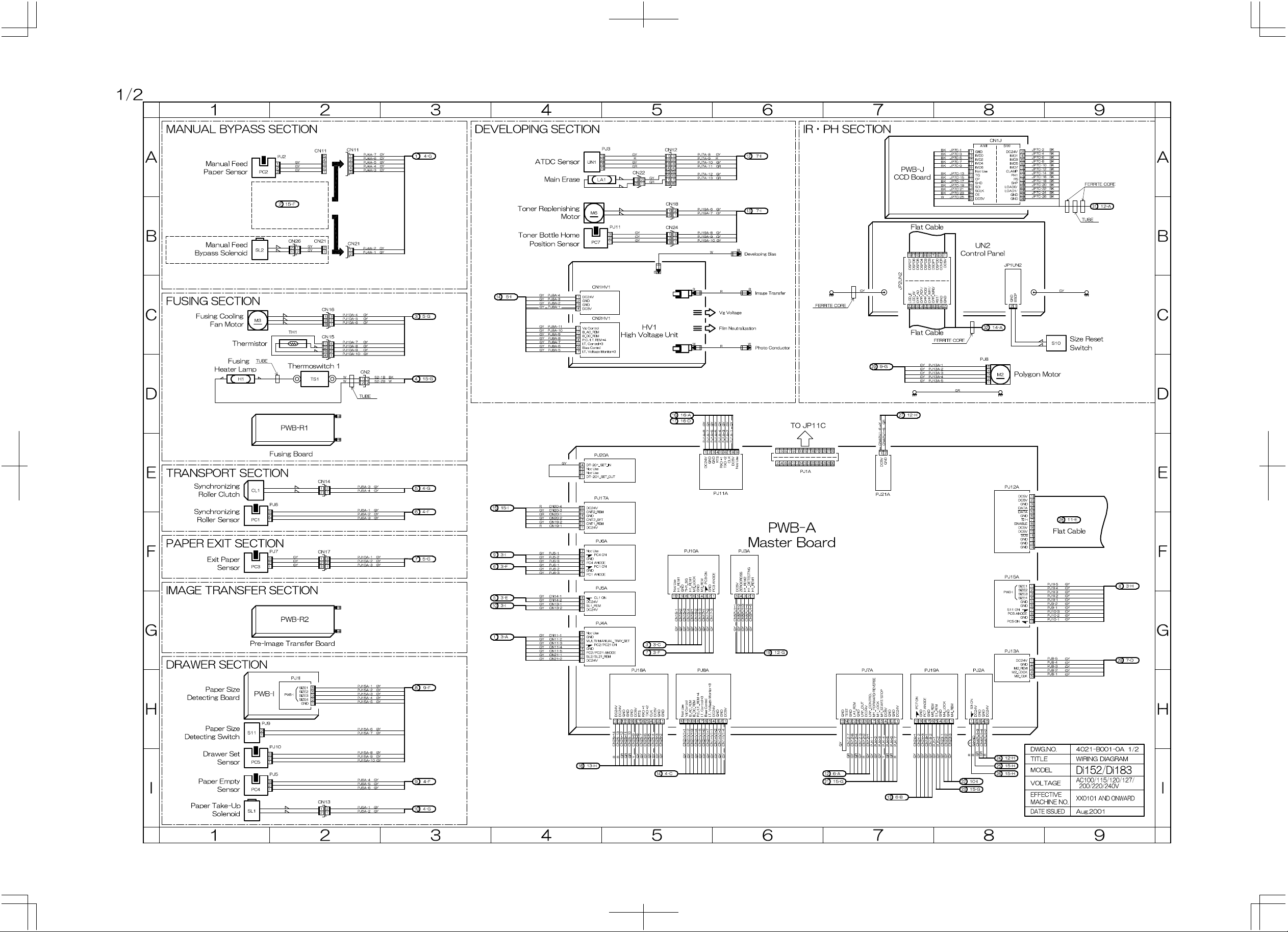
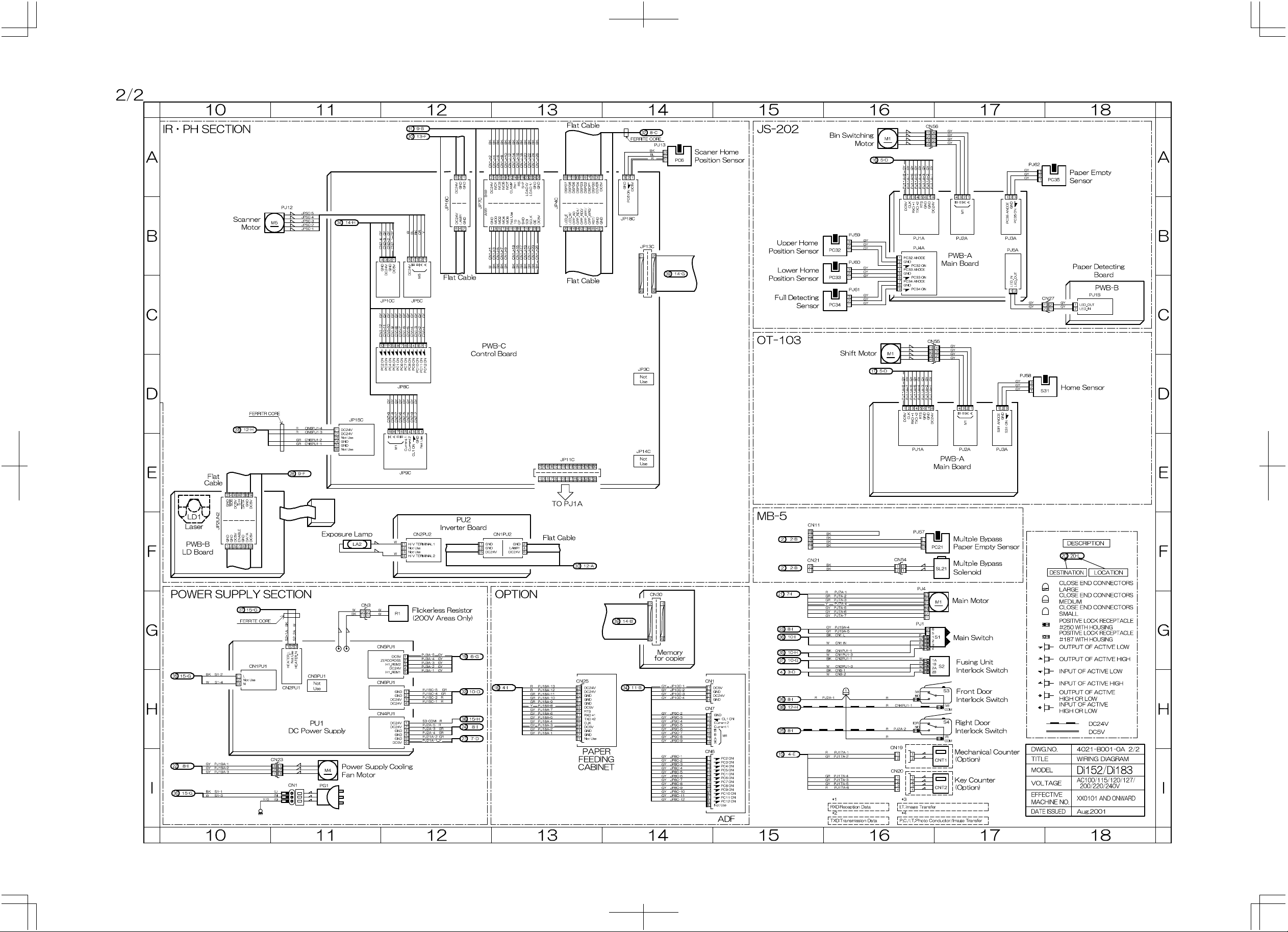
ELECTRICAL PARTS LAYOUT
A
Job Tray (JS-202)
PC35
PWB-A
PC32
PC33
PC34
M1
4689M002AB
M1
S11
M5
S2
PWB-R1
CL1
SL2
PC3
PWB-R2
PC1
UN1
PU1
TH1
PWB-J
PC4
TS1
M3
S10
UN2
PC2
PC7
S4
4021M064AA
H1
LA1
S3
M6
B
PU2
LA2
PC6
PWB-C
SL1
C
D
PWB-A
R1
E
HV1
PWB-I
PC5
S1
F
PH
M4
G
Shifting Unit (OT-103)
H
MultipIe Bypass (MB-5)
PWB-A
SL21
M1
I
S31
J
PC21
K
L
4687M001AB
4690M001AA
PWB-B
SYMBOL PART NAME LOCA TION GRID
CL1 Synchronizing Roller Clutch 1-E 4-D
CNT1 Total Counter (Option) 17-I —
CNT2 Key Counter (Option) 17-I —
H1 Fusing Heater Lamp 1-D 4~6-C~D
HV1 High Voltage Unit 4~5-C~D 3~4-D~E
LA1 Main Erase 4~5-A 5~6-D~E
LA2 Exposure Lamp 11-F 2~4-C~D
M1 Main Motor 16~17-G 4-C~D
M2 Polygon Motor
M3 Fusing Coolin g Fan Motor 1-C 5~6-C
Power Supply Cooling Fan
M4
Motor
M5 Scanner Moto r 11-B 4-B
M6 Toner Replenishing Motor 4-B 6-E
PC1 Synchronizing Roller Sensor 1- E~F 5-E
PC2 Manual Feed Paper Sensor 1~2-A 6-E
PC3 Exit Paper Sensor 1-F 5-C
PC4 Paper Empty Sensor 1-I 5-E
PC5 Drawer Set Sensor 1-I 3-E
Scanner Home Position
PC6
Sensor
Toner Bottle Home Position
PC7
Sensor
PU1 DC Power Supply 10~12-G~I 3~5-E~F
PU2 Inverter Board 12~13-F 3-C~D
PWB-A Master Board 4~8-E~H 3-D~E
PWB-B LD Board
PWB-C Control Board 11~ 1 4-A~E 3-C~D
PWB-I Paper Size Detecting Board 1~2-H 2~3-E
PWB-J CCD Board 7~8-A~B 5~6-B~C
PWB-R1 Fusing Board 1~2-D~ E 4-C
PWB-R2 Pre-Image Transfer Board 1~2-G 5-D
R1 Flickerless Resistor
S1 Main Switch 16~17-G 3-E
S2 Fusing Unit Interlock Switch
S3 Front Door Interlock Switch 16~17-H 6-E
S4 Right Door Interlock Switch 16~17-H 6-E
S10 Size Reset Switch 9-C 6-C
S11 Paper Size Detecting Sensor 1-H 3-E
SL1 Paper Take-Up Solenoid 1-I 4-D
SL2 Manual Bypass Solenoid 1-B 4-D
TH1 Thermistor 2-C 5-C
TS1 Thermoswitch 2-D 5~6-D
UN1 ATDC Sensor 4~A 5-D
UN2 Control Panel 7~8-B~C 4~7-C~D
Multiple Bypass (Option)
Multi Feed Bypass Paper
PC21
Empty Sensor
SL21 Multiple Bypass Solenoid 17-F 3-I
Job Tray (Option)
M1 Bin Switchin g M otor 16-A 14-D
PC32 Upper Home Position Sensor 16-B 13-D
PC33 Lower Home Position Sensor 16-B~C 13-D
PC34 Full Detecting Sensor 16-C 12-C
PC35 Paper Empty Sensor 17~18-A 12-C
PWB-A Main Board 16~17-A~C 12-C
PWB-B Paper Detecting Boar d 18- C 14-D
Shifting Unit (Option)
PWB-A Main Board 16~17-D~E 12~13-I
M1 Shift Motor 16-D 13-I
S31 Home Sensor 17-D 13-I
✽
1: Components used in the PH Unit
✽
2: 200 V AREAS Only
✽1
✽1
✽2
8-D —
11-I 3~4-F
14-A 2-C
4~5-B 6-E
10~11-E~F —
12-G 2-D~E
16~17-G~H
16~17-F 5-J
4-C
4021-B301-0A
Page 4

Connect.fm Page 1 Wednesday, September 12, 2001 10:47 PM
12345678910111213 1514
CONNECTORS LAYOUT
A
Job Tray (JS-202)
B
CN2
C
CN17
CN15
D
CN13
E
CN3
CN1
CN12
CN25
CN14
CN22
CN21
CN11
CN26
CN16
CN19
CN18
CN20
CN24
F
CN56
CN27
4
2
4689M001AA
CN No. LOCATION GRID
CN1 3P 11-I 2~3-F
CN2 2P 2-D 4-C
CN3 2P 11-G 2-F
CN11 5P 2-A 4-E
CN12 8P 5-A 4-D
CN13 2P 2-I 3~4-D
CN14 2P 2-E 4-D
CN15 4P 2-C~D 4-C~D
CN16 3P 2-C 5-C
CN17 3P 2-F 4-C
CN18 2P 5-B 6-F
CN19 2P 16-I 6-D
CN20 4P 16-I 6-C~D
CN21 2P 2-B 4-E
CN22 2P 5-A 4-D
CN23 3P 11-I 4-F~G
CN24 3P 5-B 6-F
CN25 14P 13-H 4-E
CN26 2P 2-B 5-E
Multiple Bypass (Option)
CN54 2P 16-F 3-I
Job Tray (Option)
CN27 2P 18-C 14-D
CN56 4P 16-A 14-D
Shifting Unit (Option)
CN55 4P 16-C~D 14-I
CN23
G
H
I
Multiple Bypass (MB-5)
CN54
2
4021D004AA
Shifting Unit (OT-103)
CN55
J
4687M002AC
K
4690M002AB
Description
L
Number of Pin Possible to confirm by removing external cover.
➀
Not possible to co nf i rm by removing external cover.
1
4021-B401-0A
 Loading...