

Page 1

FrameMaker Ver5.5E(PC) P F-120 OPTION FOR Di152/Di183
01.08.27
PF-120
SERVICE MANUAL
10794
Page 2

FrameMaker Ver.5.5(PC) PF-120 OPTION FOR Di183/Di152
01.08.27
CONTENTS
GENERAL, MECHANICAL/ELECTRICAL
1. SPECIFICATIONS ...........................................................................................M-1
2. COMPONENT IDENTIFICATION .............................................. ......................M-1
3. CROSS-SECTIONAL VIEW ............................................................................M-2
4. DRIVE SYSTEM COMPONENT LAYOUT ......................................................M-2
5. ELECTRICAL PARTS LAYOUT ...................................................................... M-3
6. PAPER TAKE-UP/FEEDING SECTION ..........................................................M-4
6-1. Edge Guide and Trailing Edge Stop ........................................................M-4
6-2. Paper Lifting Plate ...................................................................................M-4
6-3. Tray-in-Position Detection ........................ ...............................................M-5
6-4. Paper Empty Detection . ...........................................................................M-5
6-5. Paper Size Detecting Mechanism ............................................................M-6
6-6. Paper Separating Mechanism .................................................................M-7
6-7. Paper Take-Up Control . ...........................................................................M-8
6-8. Paper Take-Up Retry Control ..................................................................M-9
DIS/REASSEMBLY, ADJUSTMENT
1. DISASSEMBLY ...............................................................................................D-1
1-1. Maintenance Schedule ..................................................................... .. .... .D-1
1-2. Removal of the Paper Take-Up Rollers ...................................................D-2
1-3. Cleaning of the Paper Take-Up Roller/Rolls ............................................D-2
1-4. Cleaning of the Vert ical Transport Roller/Rolls ....................................... .D-3
2. ADJUSTMENT .................................................................................................D-4
2-1. Adjust Mode Setting Procedure ............................................................ .. .D-4
2-2. CD Registration Adjus tment ............... ........................... ..........................D-4
MISFEED DETECTION
1. MISFEED DETECTION ............................................ .......................................T-1
1-1. Location of Misfeed Detecting Sensors ...................................................T-1
1-2. Misfeed Detection Timing ........................................................................T-2
i
Page 3

FrameMaker Ver5.5E(PC) P F-120 OPTION FOR Di152/Di183
01.08.27
GENERAL,
MECHANICAL/ELECTRICAL
Page 4
FrameMaker Ver.5.5E(PC) PF-120 OPTION FOR Di152/Di183
01.08.27
1. SPECIFICATIONS
Type : Paper Feed Cabinet
Installation : Installs in the bottom of the Main Unit.
Type of Copy Paper :
Paper Sizes : Metric Areas: A5C, B5L/C, A4L/C, FLS, B4L, A3L
Registration : Center
Capacity : 250 sheets
Power Requirements : DC24 V, DC5 V (supplied from copier)
Max. Power Consumption : 9 W or less
Dimensions : Width: 590 mm or 23-1/4
Weight : 5.5 kg or 12-1/4 lbs.
(Fixed to the Main Unit by plates and screws.)
2
Plain paper, Recycled paper (60 to 90 g/m
Inch Areas: 8-1/2 × 5-1/2C, 11 × 8-1/2C, 8-1/2 × 11L,
8-1/2 × 14L, 11 × 14, 11 × 17
(L: Lengthwise, C: Crosswise)
Depth: 558 mm or 22
Height: 108 mm or 4-1/4
or 16 to 24 lbs.)
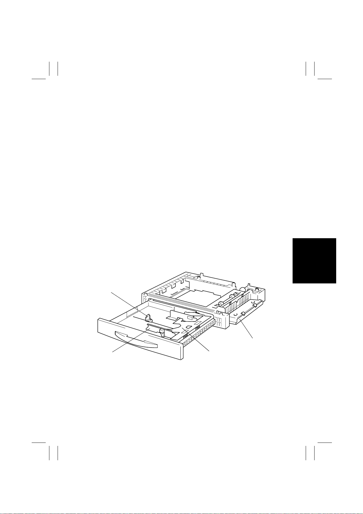
2. COMPONENT IDENTIFICATION
1
1. Trailing Edge Stop 3. Paper Lifting Plate
2. Side Door 4. Edge Guide
2
34
4686M004AA
M-1
Page 5
FrameMaker Ver.5.5E(PC) PF-120 OPTION FOR Di152/Di183
01.08.27
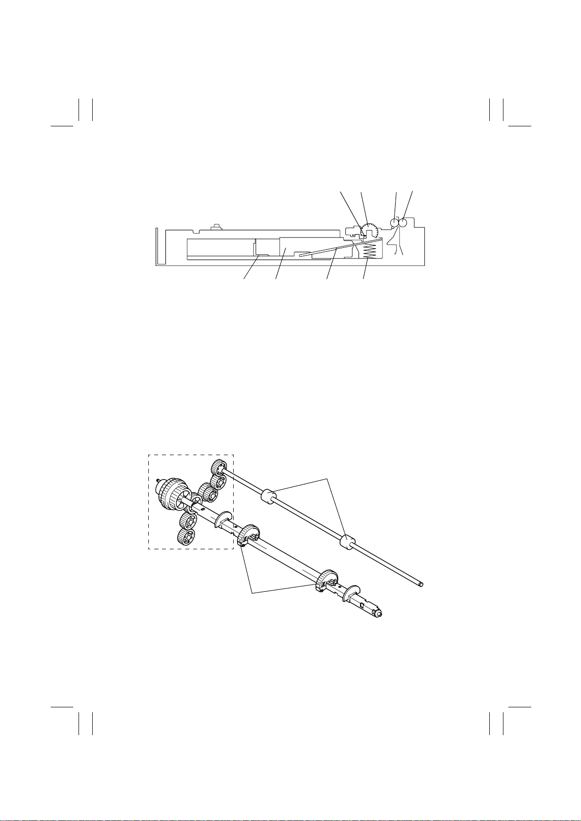
3. CROSS-SECTIONAL VIEW
1. Paper Take-Up Roll 5. Paper Lifting Spring
2. Paper Take-Up Roller 6. Paper Lifting Plate
3. Vertical T ransport Roller 7. Edge Guide
4. Vertical Transport Roll 8. Trailing Edge Stop
234
1
5678
4686M001AC
4. DRIVE SYSTEM COMPONENT LAYOUT
Vertical Transpor t Roller
Paper Take-Up
Drive Mechanism
Paper Take-Up Roller
M-2
4686M003AA
Page 6
FrameMaker Ver.5.5E(PC) PF-120 OPTION FOR Di152/Di183
01.08.27
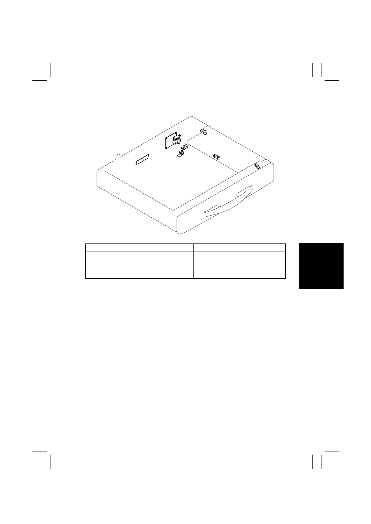
5. ELECTRICAL PARTS LAYOUT
SL11
PWB-A
PC13
PWB-I
Symbol Name Symbol Name
PWB-A
PWB-I
S11
SL11
Control Board
Paper Size (FD) Detection Board
Paper Size (CD) Detection Sensor
Paper Take-Up Solenoid
S11
PC14
PC11
PC12
PC13
PC14
PC11
PC12
Paper Empty Sensor
Paper Take-Up Sensor
Drawer Set Sensor
Side Door Sensor
4686M002AA
M-3
Page 7
FrameMaker Ver.5.5E(PC) PF-120 OPTION FOR Di152/Di183
01.08.27
6. PAPER TAKE-UP/FEEDING SECTION
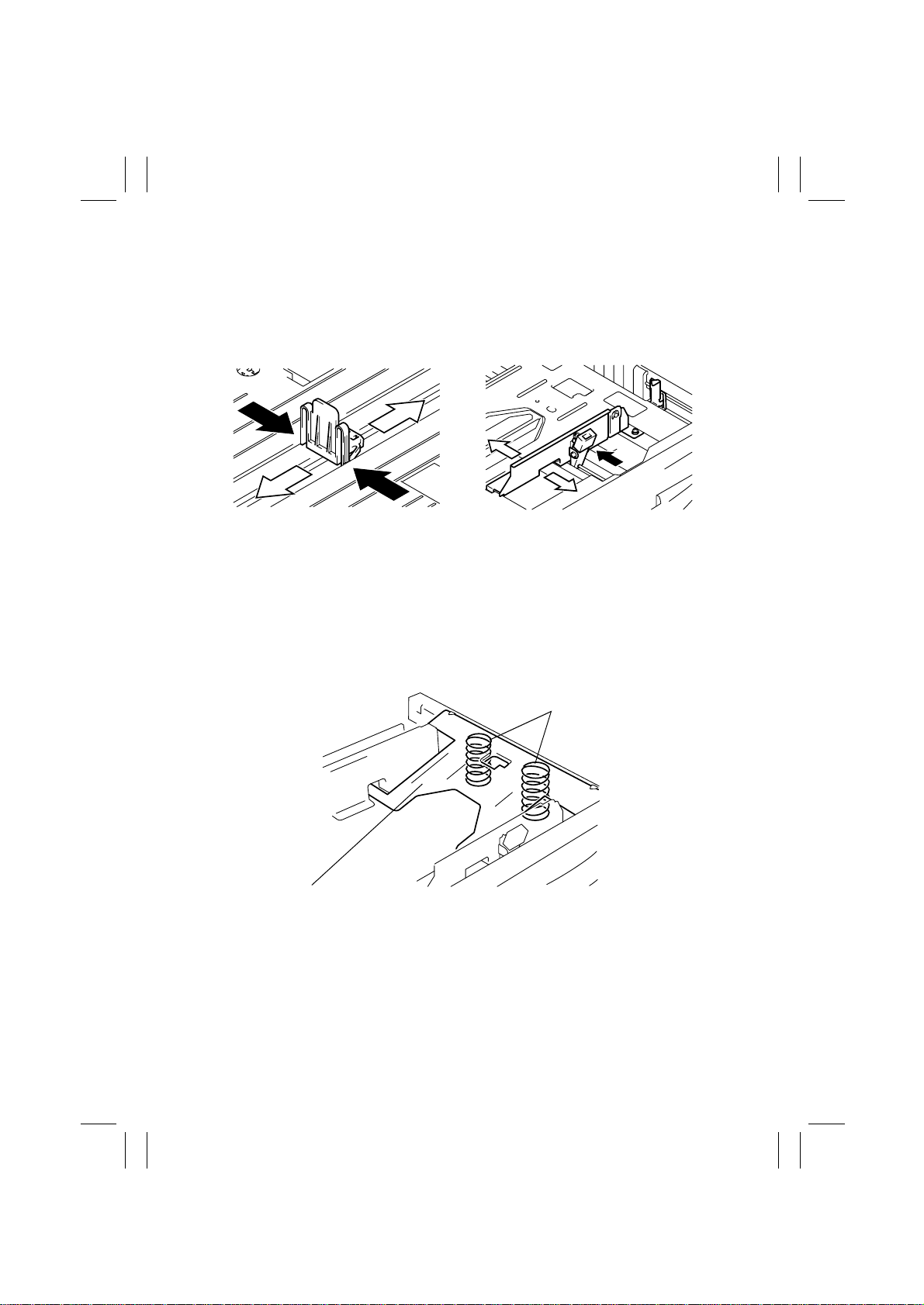
6-1. Edge Guide and Trailing Edge Stop
• The Edge Guide and Trailing Edge Stop can be slid into any desired position.
Trailing Edge Stop Edge Guide
4686M005AA
4686M009AA
6-2. Paper Lifting Plate
• The Paper Lifting Plate is locked into position when it is pressed down. It is unlocked
when the tray is slid into the unit.
• The Paper Lifting Plate is pushed upward by the Paper Lifting Springs at all times.
Paper Lifting Spring
Paper Lifting Plate
4686M006AA
M-4
Page 8

FrameMaker Ver.5.5E(PC) PF-120 OPTION FOR Di152/Di183
01.08.27
6-3. Tray-in-Position Detection
• When a tray is slid into the cabinet, the Drawer Set Sensor is blocked and the copier
determines that the tray has been slid in position.
Light Blocking Plate
Drawer Set Sensor PC13
4686M007AA
6-4. Paper Empty Detection
• The Paper Empty Sensor detects a paper-empty condition in the tray.
Paper Empty Sensor PC11
4686M008AA
M-5
Page 9

FrameMaker Ver.5.5E(PC) PF-120 OPTION FOR Di152/Di183
01.08.27
6-5. Paper Size Detecting Mechanism
• Both the width (in the crosswise direction) and length (in the feeding direction) of the
paper are detected and the copier CPU determines the paper size based on the combination of the two readings.
• The width (CD) of the paper is detected when the lever that is operatively connected to
the Edge Guide activates or deactivates the Paper Size (CD) Detection Sensor.
• The length (FD) of the paper is detected when the lever that is operatively connected to
the Trailing Edge Stop actuates or deactuates the switches on the Paper Size (FD)
Detection Board.
Paper Size (FD) Detection Board
PWB-I
SW4 SW3 SW2 SW1
Paper Size (CD) Detection Sensor
S11
Trailing Edge Stop
Paper Size (FD) Detection Board
Paper Size
SW4 SW3 SW2 SW1
A3L, LedgerL ON — — — ON
11 × 14 — — — — ON
B4L, LegalL — — — — —
FLS — — — ON —
A4L — ON ON ON —
B5L, LetterL ON ON ON ON —
A4C, LetterC ON ON — — ON
B5C ON — — ON —
A5C, InvoiceC — — ON — —
Edge Guide
PWB-I
Paper Size (CD) Detection Sensor
M-6
4686M511AA
4686M511AA
S11
Page 10

FrameMaker Ver.5.5E(PC) PF-120 OPTION FOR Di152/Di183
01.08.27
6-6. Paper Separating Mecha nism
• A loop is formed in the paper between the Separator Fingers and the Paper Take-Up
Roller. The turning force of the P aper Take-Up Roller overcomes the block of the Separator Fingers, causing the top sheet of paper to ride over the fingers and be fed out of the
tray into the copier.
• When there are only two sheets of left in the tray and if the friction force of the Paper Lifting Plate is low, the bottom sheet of paper is taken up and fed into the copier with the top
sheet of paper. To prevent this situation from occurring, there is a Friction Plate provided
on top of the Paper Lifting Plate.
• Before the Paper Take-Up Roller contacts the paper, the Paper Take-Up Roll holds the
paper down so that the paper remains stationary before its being taken up by the Paper
Take-Up Roller.
Paper Take-Up Roller
Paper
Roll
Friction Plate
Separator Finger
4686M010AA
Paper Lifting Plate
M-7
Page 11

FrameMaker Ver.5.5E(PC) PF-120 OPTION FOR Di152/Di183
01.08.27
6-7. Paper Take-Up Control
• The operation of the Paper Take-Up Solenoid is controlled by the signal output from
PJ3A-1 and 2 of the Control Board.
✽
For the 2nd Tray
(A4 crosswise, two sheets)
Start Key ON
Main Motor M1
Paper Take-Up
Solenoid SL11
Synchronizing Roller
Sensor PC1
✽
For the 3rd Tray to 5th Tray
(A4 crosswise, two sheets)
Main Motor M1
Paper Take-Up
Solenoid SL11
Paper Take-Up
Sensor PC12
ON
OFF
ON
OFF
H
L
4686M512CA
Start Key ON
ON
OFF
ON
OFF
H
L
4686M513CA
M-8
Page 12

FrameMaker Ver.5.5E(PC) PF-120 OPTION FOR Di152/Di183
01.08.27
6-8. Paper Take-Up Retry Control
• To minimize the occurrence of paper misfeed, the Paper Take-Up Solenoid is energized a
second time to carry out a paper take-up retry sequence if a sheet of paper fails to reach
the Synchronizing Roller Sensor (for the 2nd Tray) or the Paper Take-Up Sensor (for the
3rd to 5th Tra y) within a giv en period of time after a paper tak e-up sequence has been initiated. This sequence is repeated a predetermined number of times.
✽
For the 2nd Tray
No. of Paper Take-Up
Retry Sequences
Paper Take-Up Retry 1
1st Paper Take-Up
Retry Sequence
Paper Take-Up
Solenoid SL11
Synchronizing
Roller Sensor PC1
✽
For the 3rd to 5th Tray
Paper Take-Up Retry 2
Paper Take-Up
Solenoid SL11
Paper Take-Up
Sensor PC12
ON
OFF
H
L
ON
OFF
H
L
Successful paper take-up
4686M514CA
No. of Paper Take-Up
Retry Sequences
1st Paper Take-Up
Retry Sequence
2nd Paper Take-Up
Retry Sequence
Successful paper take-up
4686M515CA
M-9
Page 13

FrameMaker Ver5.5E(PC) P F-120 OPTION FOR Di152/Di183
01.08.27
DIS/REASSEMBLY,
ADJUSTMENT
Page 14

FrameMaker Ver.5.5E(PC) PF-120 OPTION FOR Di152/Di183
01.08.27
1. DISASSEMBLY
1-1. Maintenance Schedule
Maintenance
PM Parts
Paper Take-Up
Roller/Rolls
Vertical
Transport Rollers
Vertical
Transport Rolls
NOTE
• k=1,000 sheets
• The above maintenance schedule is to be based on the value of PM Counter.
(For how to show the PM Counter on the Display, see “SWITCHES ON PWBs, TECH.
REP. SETTINGS” of the Service Manual for the copier.)
• Cleaning should be performed when a paper take-up failure occurs for “ ❍” marked with
*1 and when a paper transport failure occurs for “ ❍” marked with *2.
• The parts should be replaced for each tray.
• See the Parts Manual and Parts Modification Notice for the part number.
• The above information is subject to change without notice.
Schedule Cycle
Clean Replace
*1
❍
❍
❍
150 k
*2
*2
Tools
Used for
Cleaning
Cloth,
——2☞ D-3
alcohol
——2☞ D-3
Parts No. QTY
4686-3311-XX 2
PM
Counter
2nd Tray
3rd Tray
4th Tray
5th Tray
Page
☞
D-2
D-1
Page 15

FrameMaker Ver.5.5E(PC) PF-120 OPTION FOR Di152/Di183
01.08.27
1-2. Removal of the Paper Take-Up Rollers
1. Remove two screws, two brackets, and the tray
immediately above the one for which the Paper
Take-Up Roller is to be replaced.
4686D003AA
2. Unlock the Paper Take-Up Roller and slide it off
its shaft.
4686D506AA
NOTE
• When installing the roll, make sure it securely locks
into place as illustrated.
lock point
4686D502AA
1-3. Cleaning of the Paper Take-Up Roller/Rolls
1. Remove the Paper Take-Up Roller/Rolls.
2. Wipe the surface of the Paper Take-Up Roller/
Rolls clean with a soft cloth dampened with alcohol.
4686D006AA
D-2
Page 16

FrameMaker Ver.5.5E(PC) PF-120 OPTION FOR Di152/Di183
01.08.27
1-4. Cleaning of the Vertical Transport Roller/Rolls
1. Open the Side Door.
2. Wipe the surface of the Vertical Transport Roller/
Rolls clean with a soft cloth dampened with alcohol.
4686D002AA
D-3
Page 17

FrameMaker Ver.5.5E(PC) PF-120 OPTION FOR Di152/Di183
01.08.27
2. ADJUSTMENT
2-1. Adjust Mode Setting Procedure
1. Press the Meter Count key.
2. Press the following keys in this order: Stop → 0 → 0 → Stop → 0 → 1.
3. Press the Stop key and then the Start key.
2-2. CD Registration Adjustment
Requirement:
A
4686D504AA
Adjustment Procedure
1. Set the copier into the Adjust mode.
2. With “AJ-” shown on the Display, enter the code number “12” from the 10-Key Pad.
3. Press the Paper key and select the tray.
4. Press the Start key to let the copier produce a test print.
5. Check that dimension A on the test print meets the specifications.
✽
Perf orm the following steps if dimension A falls outside the specified range.
Dimension A on the test print produced should meet
the following specifications.
✽
Specifications
A4C: 20 ± 2.0 mm
LetterC: 11.2 ± 2.0 mm
NOTE
• This adjustment should be made whenever the PH
has been replaced with a new one.
• Load the tray with A4C or LetterC paper.
6. Unload the paper stack from the tray. Loosen one
screw shown and adjust the position of the Edge
Guide in the rear.
4686U025AB
4686D505AA
Setting Procedure
• If dimension A on the test print is longer than the
specified range, move the Edge Guide to the rear.
• If dimension A on the test print is shorter than the
specified range, move the Edge Guide to the front.
7. Let the copier produce another test print and
check dimension A once again.
D-4
Page 18

FrameMaker Ver5.5E(PC) P F-120 OPTION FOR Di152/Di183
01.08.27
MISFEED DETECTION
Page 19

FrameMaker Ver.5.5E(PC) PF-120 OPTION FOR Di152/Di183
01.08.27
1. MISFEED DETECTION
1-1. Location of Misfeed Detecting Sensors
Synchronizing Roller Sensor
PC1
2nd Tray Paper Take-Up Sensor
PC12
T-1
3rd Tray Paper Take-Up Sensor
PC12
4th Tray Paper Take-Up Sensor
PC12
5th Tray Paper Take-Up Sensor
PC12
4686T512AA
Page 20

FrameMaker Ver.5.5E(PC) PF-120 OPTION FOR Di152/Di183
01.08.27
1-2. Misfeed Detection Timing
• The following lists the types of misfeed detection and detection timings for different misfeed locations.
• The symbol “L” (for the leading edge) and “T” (for the trailing edge) given in ( ) indicate
the particular edge of the paper detected by the sensor.
Type Detection Start Detection
Paper left
2nd Tra y paper tak e-up
failure
3rd Tray paper take-up
failure
4th Tray paper take-up
failure
5th Tray paper take-up
failure
Misfeed at 3rd Tray vertical
transport section
Misfeed at 4th Tray vertical
transport section
Misfeed at 5th Tray vertical
transport section
2nd Tray size error misfeed Synchronizing Roller Sensor (L)
3rd Tray size error misfeed
4th Tray size error misfeed
5th Tray size error misfeed
Power Switch ON
Misfeed reset
Paper Take-Up Solenoid of the
2nd Tray energized
Paper Take-Up Solenoid of the
3rd Tray energized
Paper Take-Up Solenoid of the
4th Tray energiz ed
Paper Take-Up Solenoid of the
5th Tray energiz ed
3rd Tray Paper Take-Up Sensor
(L)
4th Tray Paper Take-Up Sensor
(L)
5th Tray Paper Take-Up Sensor
(L)
3rd Tray Paper Take-Up Sensor
(L)
4th Tray Paper Take-Up Sensor
(L)
5th Tray Paper Take-Up Sensor
(L)
Paper Take-Up Sensor of
each tray activated
Synchronizing Roller
Sensor (L)
3rd Tray Paper Take-Up
Sensor (L)
4th Tray Paper Take-Up
Sensor (L)
5th Tray Paper Take-Up
Sensor (L)
Synchronizing Roller
Sensor (L)
3rd Tray Paper Take-Up
Sensor (L)
4th Tray Paper Take-Up
Sensor (L)
Synchronizing Roller
Sensor (T)
3rd Tray Paper Take-Up
Sensor (T)
4th Tray Paper Take-Up
Sensor (T)
5th Tray Paper Take-Up
Sensor (T)
T-2
Page 21

Page 22

 Loading...